WO2024166882A1 - 透明熱線反射膜、透明熱線反射膜の製造方法 - Google Patents
透明熱線反射膜、透明熱線反射膜の製造方法 Download PDFInfo
- Publication number
- WO2024166882A1 WO2024166882A1 PCT/JP2024/003774 JP2024003774W WO2024166882A1 WO 2024166882 A1 WO2024166882 A1 WO 2024166882A1 JP 2024003774 W JP2024003774 W JP 2024003774W WO 2024166882 A1 WO2024166882 A1 WO 2024166882A1
- Authority
- WO
- WIPO (PCT)
- Prior art keywords
- transparent heat
- heat ray
- film
- ray reflective
- reflective film
- Prior art date
- Legal status (The legal status is an assumption and is not a legal conclusion. Google has not performed a legal analysis and makes no representation as to the accuracy of the status listed.)
- Ceased
Links
Images


Classifications
-
- C—CHEMISTRY; METALLURGY
- C23—COATING METALLIC MATERIAL; COATING MATERIAL WITH METALLIC MATERIAL; CHEMICAL SURFACE TREATMENT; DIFFUSION TREATMENT OF METALLIC MATERIAL; COATING BY VACUUM EVAPORATION, BY SPUTTERING, BY ION IMPLANTATION OR BY CHEMICAL VAPOUR DEPOSITION, IN GENERAL; INHIBITING CORROSION OF METALLIC MATERIAL OR INCRUSTATION IN GENERAL
- C23C—COATING METALLIC MATERIAL; COATING MATERIAL WITH METALLIC MATERIAL; SURFACE TREATMENT OF METALLIC MATERIAL BY DIFFUSION INTO THE SURFACE, BY CHEMICAL CONVERSION OR SUBSTITUTION; COATING BY VACUUM EVAPORATION, BY SPUTTERING, BY ION IMPLANTATION OR BY CHEMICAL VAPOUR DEPOSITION, IN GENERAL
- C23C14/00—Coating by vacuum evaporation, by sputtering or by ion implantation of the coating forming material
- C23C14/06—Coating by vacuum evaporation, by sputtering or by ion implantation of the coating forming material characterised by the coating material
- C23C14/08—Oxides
-
- C—CHEMISTRY; METALLURGY
- C23—COATING METALLIC MATERIAL; COATING MATERIAL WITH METALLIC MATERIAL; CHEMICAL SURFACE TREATMENT; DIFFUSION TREATMENT OF METALLIC MATERIAL; COATING BY VACUUM EVAPORATION, BY SPUTTERING, BY ION IMPLANTATION OR BY CHEMICAL VAPOUR DEPOSITION, IN GENERAL; INHIBITING CORROSION OF METALLIC MATERIAL OR INCRUSTATION IN GENERAL
- C23C—COATING METALLIC MATERIAL; COATING MATERIAL WITH METALLIC MATERIAL; SURFACE TREATMENT OF METALLIC MATERIAL BY DIFFUSION INTO THE SURFACE, BY CHEMICAL CONVERSION OR SUBSTITUTION; COATING BY VACUUM EVAPORATION, BY SPUTTERING, BY ION IMPLANTATION OR BY CHEMICAL VAPOUR DEPOSITION, IN GENERAL
- C23C14/00—Coating by vacuum evaporation, by sputtering or by ion implantation of the coating forming material
- C23C14/06—Coating by vacuum evaporation, by sputtering or by ion implantation of the coating forming material characterised by the coating material
- C23C14/08—Oxides
- C23C14/083—Oxides of refractory metals or yttrium
-
- C—CHEMISTRY; METALLURGY
- C01—INORGANIC CHEMISTRY
- C01G—COMPOUNDS CONTAINING METALS NOT COVERED BY SUBCLASSES C01D OR C01F
- C01G41/00—Compounds of tungsten
-
- C—CHEMISTRY; METALLURGY
- C23—COATING METALLIC MATERIAL; COATING MATERIAL WITH METALLIC MATERIAL; CHEMICAL SURFACE TREATMENT; DIFFUSION TREATMENT OF METALLIC MATERIAL; COATING BY VACUUM EVAPORATION, BY SPUTTERING, BY ION IMPLANTATION OR BY CHEMICAL VAPOUR DEPOSITION, IN GENERAL; INHIBITING CORROSION OF METALLIC MATERIAL OR INCRUSTATION IN GENERAL
- C23C—COATING METALLIC MATERIAL; COATING MATERIAL WITH METALLIC MATERIAL; SURFACE TREATMENT OF METALLIC MATERIAL BY DIFFUSION INTO THE SURFACE, BY CHEMICAL CONVERSION OR SUBSTITUTION; COATING BY VACUUM EVAPORATION, BY SPUTTERING, BY ION IMPLANTATION OR BY CHEMICAL VAPOUR DEPOSITION, IN GENERAL
- C23C14/00—Coating by vacuum evaporation, by sputtering or by ion implantation of the coating forming material
- C23C14/22—Coating by vacuum evaporation, by sputtering or by ion implantation of the coating forming material characterised by the process of coating
- C23C14/24—Vacuum evaporation
- C23C14/28—Vacuum evaporation by wave energy or particle radiation
-
- C—CHEMISTRY; METALLURGY
- C23—COATING METALLIC MATERIAL; COATING MATERIAL WITH METALLIC MATERIAL; CHEMICAL SURFACE TREATMENT; DIFFUSION TREATMENT OF METALLIC MATERIAL; COATING BY VACUUM EVAPORATION, BY SPUTTERING, BY ION IMPLANTATION OR BY CHEMICAL VAPOUR DEPOSITION, IN GENERAL; INHIBITING CORROSION OF METALLIC MATERIAL OR INCRUSTATION IN GENERAL
- C23C—COATING METALLIC MATERIAL; COATING MATERIAL WITH METALLIC MATERIAL; SURFACE TREATMENT OF METALLIC MATERIAL BY DIFFUSION INTO THE SURFACE, BY CHEMICAL CONVERSION OR SUBSTITUTION; COATING BY VACUUM EVAPORATION, BY SPUTTERING, BY ION IMPLANTATION OR BY CHEMICAL VAPOUR DEPOSITION, IN GENERAL
- C23C14/00—Coating by vacuum evaporation, by sputtering or by ion implantation of the coating forming material
- C23C14/22—Coating by vacuum evaporation, by sputtering or by ion implantation of the coating forming material characterised by the process of coating
- C23C14/34—Sputtering
- C23C14/3407—Cathode assembly for sputtering apparatus, e.g. Target
-
- C—CHEMISTRY; METALLURGY
- C23—COATING METALLIC MATERIAL; COATING MATERIAL WITH METALLIC MATERIAL; CHEMICAL SURFACE TREATMENT; DIFFUSION TREATMENT OF METALLIC MATERIAL; COATING BY VACUUM EVAPORATION, BY SPUTTERING, BY ION IMPLANTATION OR BY CHEMICAL VAPOUR DEPOSITION, IN GENERAL; INHIBITING CORROSION OF METALLIC MATERIAL OR INCRUSTATION IN GENERAL
- C23C—COATING METALLIC MATERIAL; COATING MATERIAL WITH METALLIC MATERIAL; SURFACE TREATMENT OF METALLIC MATERIAL BY DIFFUSION INTO THE SURFACE, BY CHEMICAL CONVERSION OR SUBSTITUTION; COATING BY VACUUM EVAPORATION, BY SPUTTERING, BY ION IMPLANTATION OR BY CHEMICAL VAPOUR DEPOSITION, IN GENERAL
- C23C14/00—Coating by vacuum evaporation, by sputtering or by ion implantation of the coating forming material
- C23C14/22—Coating by vacuum evaporation, by sputtering or by ion implantation of the coating forming material characterised by the process of coating
- C23C14/54—Controlling or regulating the coating process
-
- C—CHEMISTRY; METALLURGY
- C01—INORGANIC CHEMISTRY
- C01P—INDEXING SCHEME RELATING TO STRUCTURAL AND PHYSICAL ASPECTS OF SOLID INORGANIC COMPOUNDS
- C01P2002/00—Crystal-structural characteristics
- C01P2002/70—Crystal-structural characteristics defined by measured X-ray, neutron or electron diffraction data
- C01P2002/72—Crystal-structural characteristics defined by measured X-ray, neutron or electron diffraction data by d-values or two theta-values, e.g. as X-ray diagram
-
- C—CHEMISTRY; METALLURGY
- C01—INORGANIC CHEMISTRY
- C01P—INDEXING SCHEME RELATING TO STRUCTURAL AND PHYSICAL ASPECTS OF SOLID INORGANIC COMPOUNDS
- C01P2002/00—Crystal-structural characteristics
- C01P2002/70—Crystal-structural characteristics defined by measured X-ray, neutron or electron diffraction data
- C01P2002/74—Crystal-structural characteristics defined by measured X-ray, neutron or electron diffraction data by peak-intensities or a ratio thereof only
-
- C—CHEMISTRY; METALLURGY
- C01—INORGANIC CHEMISTRY
- C01P—INDEXING SCHEME RELATING TO STRUCTURAL AND PHYSICAL ASPECTS OF SOLID INORGANIC COMPOUNDS
- C01P2002/00—Crystal-structural characteristics
- C01P2002/80—Crystal-structural characteristics defined by measured data other than those specified in group C01P2002/70
- C01P2002/85—Crystal-structural characteristics defined by measured data other than those specified in group C01P2002/70 by XPS, EDX or EDAX data
-
- C—CHEMISTRY; METALLURGY
- C01—INORGANIC CHEMISTRY
- C01P—INDEXING SCHEME RELATING TO STRUCTURAL AND PHYSICAL ASPECTS OF SOLID INORGANIC COMPOUNDS
- C01P2006/00—Physical properties of inorganic compounds
- C01P2006/40—Electric properties
-
- C—CHEMISTRY; METALLURGY
- C01—INORGANIC CHEMISTRY
- C01P—INDEXING SCHEME RELATING TO STRUCTURAL AND PHYSICAL ASPECTS OF SOLID INORGANIC COMPOUNDS
- C01P2006/00—Physical properties of inorganic compounds
- C01P2006/60—Optical properties, e.g. expressed in CIELAB-values
-
- C—CHEMISTRY; METALLURGY
- C01—INORGANIC CHEMISTRY
- C01P—INDEXING SCHEME RELATING TO STRUCTURAL AND PHYSICAL ASPECTS OF SOLID INORGANIC COMPOUNDS
- C01P2006/00—Physical properties of inorganic compounds
- C01P2006/80—Compositional purity
- C01P2006/82—Compositional purity water content
Definitions
- the present invention relates to a transparent heat ray reflective film and a method for manufacturing the transparent heat ray reflective film.
- Window components such as plate glass provided with a film that transmits visible light and blocks near-infrared rays that cause heat rays are used in car windows, building windows, etc.
- window components are broadly divided into absorption-type infrared shielding films, in which an infrared absorbing microparticle dispersion, in which infrared absorbing material microparticles are dispersed in a resin that is transparent to visible light, is arranged on the surface of a transparent substrate such as plate glass, and reflection-type infrared shielding films, in which an infrared reflective film is arranged on the surface of a transparent substrate such as plate glass.
- absorption-type infrared shielding film in Patent Documents 1 and 2.
- Absorption-type infrared shielding films exhibit electrical insulation properties, and therefore do not reflect radio waves used for communication, etc., as described below. For this reason, even when used on windows, radio waves used for communication, etc., can penetrate into the room, and communication interference with mobile phones and the like does not occur.
- absorption-type infrared shielding films have the problem that infrared rays absorbed by sunlight heat up the substrate and dispersion.
- reflective infrared shielding films use plasma reflection by a film with metallic conductivity to reflect heat rays.
- the best reflection characteristics are obtained by a thin film sputtered with Ag, and a multilayer film is used consisting of Ag and a dielectric to improve visible light transmittance (Patent Documents 3 and 4).
- Radio waves for mobile phones and other mobile communications are in the UHF band (0.3 GHz to 3 GHz). Particularly useful radio waves for communication are in the 0.9 GHz to 2.2 GHz frequency band, and radio waves used for wireless LANs (wireless local area networks) are in the 2.45 GHz and 5.2 GHz bands. Technological development is underway with the goal of using the even shorter wavelength SHF band (3 GHz to 30 GHz) for high-speed data communications and satellite communications.
- a transparent heat ray reflective film it is preferable for a transparent heat ray reflective film to be able to transmit radio waves in these frequency bands.
- transparent heat ray reflective films made of thin metallic films reflect radio waves in the GHz and MHz bands used for signal transmission in these communications, etc., so measures must be taken, such as making cuts in parts of the film. This is true not only for metal films, but also for transparent heat ray reflective films made of transparent conductive oxides such as ITO (indium-tin-oxide), which is indium oxide doped with a few mol percent tin, and zinc oxide (AZO, GZO) doped with a few mol percent Al or Ga.
- ITO indium-tin-oxide
- AZO, GZO zinc oxide
- a transparent heat ray reflective film is required to have at least a high surface resistance.
- no transparent heat ray reflective film using metal plasma reflection has had such a high surface resistance and is transparent to radio waves until now, so a new transparent heat ray reflective film with high surface resistance and the ability to transmit radio waves was needed.
- one aspect of the present invention aims to provide a transparent heat ray reflective film with a high surface resistance.
- a transparent heat ray reflective film is provided, which is a continuous film of a plasma reflective material and is non-conductive.
- a transparent heat ray reflective film with high surface resistance can be provided.
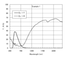
- FIG. 1 shows the transmittance spectrum and the reflectance spectrum of the transparent heat ray reflective film of Example 1.
- FIG. 2 shows the XPS W-4f spectrum of the transparent heat ray reflective film of Example 1 and the four components with separated peaks.
- FIG. 3 shows the XPS O-1s spectrum of the transparent heat ray reflective film of Example 1 and the four components with separated peaks.
- FIG. 4 shows XRD profiles of the transparent heat ray reflective films of Examples 1 to 7 and Cs 0.32 WO 3 standard data (ICDD83-1334).
- FIG. 5 shows the transmittance spectrum and the reflectance spectrum of the transparent heat ray reflective film of Example 2.
- FIG. 6 shows the transmittance spectrum and the reflectance spectrum of the transparent heat ray reflective film of Example 3.
- FIG. 5 shows the transmittance spectrum and the reflectance spectrum of the transparent heat ray reflective film of Example 2.
- FIG. 7 shows the transmittance spectrum and the reflectance spectrum of the transparent heat ray reflective film of Example 4.
- FIG. 8 shows the transmittance spectrum and the reflectance spectrum of the transparent heat ray reflective film of Example 5.
- FIG. 9 shows the transmittance spectrum and the reflectance spectrum of the transparent heat ray reflective film of Example 6.
- FIG. 10 shows the transmittance spectrum and the reflectance spectrum of the transparent heat ray reflective film of Example 7.
- FIG. 11 shows the transmittance spectrum and the reflectance spectrum of the film of Comparative Example 1.
- FIG. 12 shows the transmittance spectrum and the reflectance spectrum of the film of Comparative Example 2.
- FIG. 13 shows the transmittance spectrum and the reflectance spectrum of the film of Comparative Example 3.
- FIG. 14 shows XRD profiles of the films obtained in Comparative Examples 1 to 3 and Cs 0.32 WO 3 standard data (ICDD83-1334).
- FIG. 15 is a photograph showing the appearance of the transparent heat ray reflective films obtained in Examples 1 to 7 and the films obtained in Comparative Examples 1 to 3.
- the transparent heat ray reflective film of this embodiment is a continuous film made of a plasma reflective material and is non-conductive.
- Plasma-reflecting material Plasma reflection is a phenomenon that occurs in systems that have a large number of free electrons, such as metals. The presence of a large number of free electrons usually gives the material high electrical conductivity, but the film according to this embodiment is non-conductive. This seemingly contradictory physical property is the central feature of this embodiment.
- the plasma-reflecting material means a material that has the property of reflecting incident electromagnetic waves by collective excitation of free electrons, and has a maximum reflectance of 30% or more in the wavelength range of 780 nm to 2600 nm.
- N free electron density (1/cm -3
- m mass of electron (g)
- a continuous film of a plasma-reflecting material is defined as a film having a maximum plasma reflection value, i.e., a maximum reflectance value of 30% or more in the wavelength range of 780 nm to 2600 nm, taking into consideration industrial usefulness.
- being non-conductive means that the surface resistance of the film is 10 5 ⁇ / ⁇ or more.
- the surface resistance of a film is 10 5 ⁇ / ⁇ or more, it can be evaluated as having a high surface resistance.
- the reflection characteristics of radio waves are closely related to the surface resistance of the film. In general, the higher the surface resistance, the better the radio wave transmission. When the surface resistance is 10 5 ⁇ / ⁇ or more, considerable transmission is achieved for radio waves in the VHF and UHF bands. Furthermore, when the surface resistance is 10 6 ⁇ / ⁇ or more, radio wave transmission is almost equivalent to that of float glass for all radio waves in the VHF, UHF, and SHF bands (Non-Patent Document 1).
- the transparent heat ray reflective film preferably has a surface resistance value of 10 5 ⁇ / ⁇ or more, and more preferably 10 6 ⁇ / ⁇ or more.
- the plasma reflective material used in the transparent heat ray reflective film of this embodiment is not particularly limited, but preferably contains an alkali tungsten bronze that shows a hexagonal crystal pattern in powder X-ray diffraction measurement. It is more preferable that the plasma reflective material contains, as a main component, an alkali tungsten bronze that shows a hexagonal crystal pattern in powder X-ray diffraction measurement. Containing as a main component means that it is contained in the largest amount by mass percentage.
- the plasma reflective material can also be composed of an alkali tungsten bronze that shows a hexagonal crystal pattern in powder X-ray diffraction measurement, but this does not exclude the inclusion of unavoidable impurities even in this case. Note that alkali tungsten bronze means tungsten bronze that contains an alkali metal element.
- Non-Patent Document 2 Some tungsten bronzes containing alkali metal elements can have a hexagonal crystal structure. It has recently become clear that this hexagonal crystal structure often contains lattice defects on the basal and prism faces, and it has been reported that when these defects are present, extra diffraction lines appear in addition to the diffraction lines of the hexagonal crystal pattern in powder X-ray diffraction measurements (Non-Patent Document 2).
- the plasma-reflective material used in the transparent heat ray reflective film of this embodiment can basically contain alkali tungsten bronze that exhibits a hexagonal crystal pattern in powder X-ray diffraction measurement, regardless of whether or not there is an excess diffraction line.
- the alkali tungsten bronze that exhibits a hexagonal crystal pattern in this specification can be either an alkali tungsten bronze that includes lattice defects in the hexagonal crystal structure, or an alkali tungsten bronze that does not include lattice defects in the hexagonal crystal structure.
- the alkali tungsten bronze contained in the plasma reflective substance is preferably represented by the general formula AxWyOz (0.05 ⁇ x/y ⁇ 0.5, 2.5 ⁇ z/y ⁇ 3.0, element A contains one or more alkali metal elements selected from Na, K, Rb and Cs).
- Element A may further contain elements other than the above alkali metal elements.
- Element A may further contain one or more additive elements (substituting elements) selected from, for example, Tl, In, Li, Be, Mg, Ca, Sr, Ba, Al, Ga, and Ti.
- additive elements substituted elements
- the degree or ratio of the additive elements contained in element A is not particularly limited and may be selected as desired depending on the required characteristics, etc.
- the alkali tungsten bronze contained in the transparent heat ray reflective film of this embodiment preferably has a ratio of W5 + , which is a localized electron, to the total number of W atoms of 0.20 or more.
- the localized electrons may include W4 + , but in hexagonal alkali tungsten bronzes, most of the localized electrons are observed as W5 + .
- the localized electrons in hexagonal alkali tungsten bronzes can be determined by X-ray photoelectron spectroscopy (XPS).
- the photoelectron spectrum of the hexagonal alkali tungsten bronze contained in the sample is measured by X-ray photoelectron spectroscopy, and the W4f spectrum of the tungsten atoms is peak-separated into its constituent components to obtain the W5+ spectrum.
- the constituent components include W6 + , W5 + , W4 + , and W.
- the ratio of the area of the W5 + spectrum to the area of the W4f spectrum of the tungsten atoms in the photoelectron spectrum can be regarded as the ratio of the W5 + localized electrons to all W atoms.
- the presence of many localized electrons in hexagonal alkali tungsten bronze introduces potential disturbance, reduces the mobility of free electrons, and is the main cause of the non-conductivity of the film.
- the effect of metal-insulator transition occurring with an increase in localized electrons is considered to be a phenomenon related to the insulating mechanism in disordered systems called Anderson transition and the insulating mechanism in strongly correlated electron systems called Mott transition.
- W5 + localized electrons are bound to W ions and are not basically free electrons that can move freely, but they contribute to the occurrence of plasma reflection of near-infrared rays together with free electrons through some mechanism.
- the ratio of W5 + which is the localized electron in the crystal of alkali tungsten bronze, to all W atoms (W5 + /W value) is preferably 0.20 or more, more preferably 0.30 or more, and even more preferably 0.40 or more.
- the alkali tungsten bronze crystals are preferentially oriented in a direction in which the (0001) plane, which is the hexagonal basal plane, is parallel to the film surface.
- the peak diffraction intensity ratio I 0002 /I 20-20 in the X-ray diffraction pattern is larger than the same peak diffraction intensity ratio I 0002 /I 20-20 in a sample that is not oriented.
- the alkali tungsten bronze contained in the transparent heat ray reflective film of this embodiment is assumed to be Cs 0.32 WO 3.
- the peak diffraction intensity ratio I 0002 /I 20-20 in the standard powder pattern (ICDD 83-1334), which is a sample without crystal orientation can be made the standard intensity ratio (p std ).
- the transparent heat ray reflective film of this embodiment is preferably a film in which p>p std .
- the crystal anisotropy of the alkali tungsten bronze affects the charge transport phenomenon in the film.
- DFT calculations density functional theory
- the charge distribution in the c-axis direction is delocalized, but in the a-axis and b-axis directions it is basically localized, with some being delocalized (Non-Patent Document 4). Therefore, when the (0001) plane orientation exists, charge transport on the film surface is suppressed, increasing the surface resistance value. Conversely, when the film is oriented along the a-axis, it contributes to a decrease in the surface resistance value.
- the transparent heat ray reflective film of the present embodiment preferably has optical properties such that the visible light transmittance is preferably 5% or more, more preferably 10% or more, and even more preferably 20% or more, and the reflectance at a wavelength of 1400 nm, which is in the near-infrared region, is 30% or more.
- front windshield glass and front door glass are regulated to have a visible light transmittance of 70% or more or 75% or more, depending on the country.
- rear door glass and back windows use glass with a low visible light transmittance of 20% to 30% from the perspective of privacy protection.
- the transparent heat ray reflective film of this embodiment By applying the transparent heat ray reflective film of this embodiment to, for example, a glass substrate, it is possible to provide glass having strong heat ray reflective performance over a wide range from low to high visible light transmittance. (Surface resistance value) As described above, it is necessary to ensure the transparency of radio waves used for communication, etc. in the windows of automobiles, etc. Therefore, the surface resistance of the transparent heat ray reflective film of this embodiment is preferably 10 5 ⁇ / ⁇ or more, and more preferably 10 6 ⁇ / ⁇ or more.
- the surface resistance value of the transparent heat ray reflective film By setting the surface resistance value of the transparent heat ray reflective film within the above range, it is possible to improve the transmittance of radio waves used in communications, etc.
- the surface resistance value of the transparent heat ray reflective film is preferably, for example, 10 11 ⁇ / ⁇ or less.
- the moisture content in the film is preferably 5.0 mol% or less, more preferably 0.05 mol% to 5.0 mol%, even more preferably 0.05 mol% to 4.0 mol%, and particularly preferably 0.05 mol% to 3.0 mol%.
- Alkaline tungsten bronze has a property of easily incorporating various molecules derived from water, such as O, OH, OH 2 , and H 3 O, and excess oxygen into its basal and prism surfaces. When these water-derived molecules and excess oxygen are incorporated, lattice defects in which W is missing are introduced into the basal and prism surfaces.
- W valence electrons are the main source of free electrons and localized electrons in alkali tungsten bronze through oxygen vacancies, and are the source of film conductivity and optical functions, so there is a risk that W vacancies will significantly increase the surface resistance and reduce the near-infrared reflection and absorption function.
- Such a dry continuous film has been disclosed as a transparent heat ray absorbing film (Patent Document 4).
- the thickness of the transparent heat ray reflective film of the present embodiment is not particularly limited, but is preferably 10 nm to 600 nm.
- the transparent heat ray reflective film of the present embodiment is a film obtained by a pulsed laser deposition method, a sputtering method, or the like, as described below, there is no need to use a dispersant or a medium resin, and it can be formed thinly and uniformly.
- the film thickness of the transparent heat ray reflective film of this embodiment 10 nm or more it is possible to obtain a transparent heat ray reflective film with high heat ray reflectance.
- the film thickness 10 nm or more it is possible to prevent the film from becoming island-shaped and also to prevent unevenness in the reflection characteristics.
- the thickness of the transparent heat ray reflective film of the present embodiment is 600 nm or less, the visible light transmittance can be increased and coloring of the film can be suppressed. In addition, the amount of target used during production can be reduced, and the film formation time can be reduced, thereby improving productivity.
- Method of manufacturing transparent heat ray reflective film Next, a configuration example of the method for producing the transparent heat ray reflective film of the present embodiment will be described. Since the method for producing the transparent heat ray reflective film of the present embodiment can produce the transparent heat ray reflective film described above, some of the items already described will not be described.
- the transparent heat ray reflective film of the present embodiment can be produced, for example, by dry film formation. Therefore, the method for producing the transparent heat ray reflective film of the present embodiment can include a film formation step of dry-forming a plasma reflective substance as a non-conductive continuous film on the surface of a substrate.
- the plasma-reflecting material preferably contains an alkali tungsten bronze that exhibits a hexagonal crystal pattern in powder X-ray diffraction measurement, and is preferably represented by the general formula AxWyOz (0.05 ⁇ x/y ⁇ 0.5, 2.5 ⁇ z/y ⁇ 3.0, element A contains one or more alkali metal elements selected from Na, K, Rb, and Cs) as described above.
- the raw materials used in dry film formation can be, for example, a tungsten source and an alkali metal element source that can form alkali tungsten bronze.
- a composite tungsten oxide of a specific composition can also be used as the raw material used in dry film formation.
- the tungsten source can be one or more selected from tungsten and tungsten compounds.
- alkali metal element source one or more types selected from compounds of alkali metal elements and hydrates of compounds of alkali metal elements can be used.
- tungstic acid H 2 WO 4
- Tungsten trioxide powder obtained by calcining tungsten acid may be used as the raw material of the tungsten source, or a commercially available tungsten trioxide powder may be used.
- tungsten oxide or composite tungsten oxide can be used as the tungsten source.
- tungsten oxide tungsten oxide powder represented by W a O b (wherein W is tungsten, O is oxygen, 2.2 ⁇ b/a ⁇ 3.0) can be used.
- composite tungsten oxide for example, composite tungsten oxide powder represented by the general formula A x1 W y1 O z1 (wherein A is the element A, W is tungsten, O is oxygen, 0.001 ⁇ x1/y1 ⁇ 1, 2.2 ⁇ z1/y1 ⁇ 3.0) can be used.
- the raw material used to form the film is preferably a mixture of a tungsten source and an alkali metal element source, for example, so that the formed film has the desired composition.
- the raw material may be, for example, a mixture of a tungsten source and an alkali metal element source. More specific examples of the raw material include a mixed powder of tungstic acid (H 2 WO 4 ) and one or more selected from the oxides and hydroxides of alkali metal elements, and a mixed powder of tungsten trioxide and one or more selected from the oxides and hydroxides of alkali metal elements.
- the tungsten source and the alkali metal element source do not need to be composed of one raw material each, and may be a mixture of multiple types of raw materials. Therefore, a mixed powder obtained by mixing a mixture of tungsten acid (H 2 WO 4 ) and tungsten trioxide powder with one or more types selected from oxides and hydroxides of alkali metal elements can also be used as a raw material.
- a mixed powder obtained by mixing a mixture of tungsten acid (H 2 WO 4 ) and tungsten trioxide powder with one or more types selected from oxides and hydroxides of alkali metal elements can also be used as a raw material.
- the tungsten source and the alkali metal element source are not limited to solid materials.
- a product powder obtained by mixing one or more selected from tungstic acid (H 2 WO 4 ) and tungsten trioxide powder with one or more selected from an aqueous solution of a metal salt containing an alkali metal element, a colloidal solution of a metal oxide, and an alkoxy solution, drying the dried powder, and firing the dried powder under an atmosphere of an inert gas or a mixed gas of an inert gas and a reducing gas can be used as the raw material.
- the element A can contain one or more alkali metal elements selected from Na, K, Rb, and Cs as described above, but the element A can also contain one or more elements selected from Tl, In, Li, Be, Mg, Ca, Sr, Ba, Al, Ga, and Ti.
- the transparent heat ray reflective film can be formed, for example, by using a pellet formed by molding the above-mentioned raw material or a sintered target.
- Alkaline tungsten bronze is not a thermodynamic equilibrium phase, but a non-equilibrium substance in a weakly reducing state. Therefore, in dry film formation, a method that can achieve a substantially weakly reducing atmosphere during the film formation process can be preferably used.
- the method for producing the transparent heat ray reflective film of this embodiment it is preferable to use any one of the magnetron sputtering method, ion beam sputtering method, direct current sputtering method, radio frequency sputtering method, pulse sputtering method, dual magnetron sputtering method, electron beam vacuum deposition method, and pulse laser deposition method for dry film formation, which uses a target containing tungsten and the alkali metal elements that make up the alkali tungsten bronze.
- a DC sputtering method in which a DC voltage is applied to the target is more preferable. This is because the DC sputtering method has a simple power supply configuration and is highly productive.
- dry film formation can be performed using radio frequency sputtering, pulse sputtering, dual magnetron sputtering, and ion beam sputtering.
- Pulsed Laser Deposition is a film formation method in which a raw material target placed inside a vacuum chamber is irradiated with laser light from outside the vacuum chamber. This operation causes atoms or molecules to be peeled off (ablated) from the target, forming a thin film on a substrate facing the target. Pulsed Laser Deposition is effective for target materials that have a high absorption of the irradiated laser.
- pulsed laser deposition does not require plasma gases such as argon, which is necessary for sputtering. Furthermore, since it is said that the target composition can be transferred to the film on the substrate, a film with the desired composition can be easily formed.
- the transparent heat ray reflective film of this embodiment preferably has a moisture content within a predetermined range. Therefore, in the method for producing a transparent heat ray reflective film of this embodiment, it is preferable to control the moisture content in the atmosphere during the film formation process. When controlling the moisture content in the atmosphere during film formation in this way, it is preferable to also take into account the moisture released from the target. In order to suppress the moisture released from the target, it is preferable that the target is small. Furthermore, the pulsed laser deposition method can be used with a tablet target with a diameter of about 20 mm. For this reason, the pulsed laser deposition method can be used preferably.
- the simplest method is to use a single target composed of a compound containing tungsten and the alkali metal elements that make up the alkali tungsten bronze.
- a target containing an alkali metal element and a target containing tungsten may be used to deposit films simultaneously or alternately with two or more elements.
- the composition ratio of the elements contained in the resulting film may also be adjusted by depositing films simultaneously or alternately with two or more elements using two or more targets with different composition ratios containing an alkali metal element and tungsten.
- the duty ratio of the laser irradiated onto the target is small, so there is no need to cool the target. Because targets used in pulsed laser deposition do not need to be cooled, they do not require the backing plate that is provided with targets used in sputtering.
- Oxygen, nitrogen, carbon, etc. contained in the target may be exhausted during film formation, and can be adjusted by introducing a reactive gas during film formation.
- oxygen for example, can be used as the reactive gas.
- the transparent heat ray reflective film of this embodiment it is preferable not to take in moisture during film formation. For this reason, it is preferable to form a continuous crystal thin film containing alkali tungsten bronze on the substrate surface under film formation conditions that prevent moisture from entering from the inner wall of the vacuum chamber, the target, etc.
- the ultimate vacuum level before pre-sputtering of the target or introduction of the reactive gas is preferably less than 1 ⁇ 10 ⁇ 4 Pa, and more preferably less than 1 ⁇ 10 ⁇ 5 Pa.
- the moisture pressure in the atmosphere during the film formation step is preferably less than 1 ⁇ 10 ⁇ 4 Pa, and more preferably less than 1 ⁇ 10 ⁇ 5 Pa.
- a cryopump, cryopanel, or cryocoil with a high water exhaust speed in addition to baking the general vacuum chamber. Furthermore, reducing the surface area of the inner wall of the vacuum chamber, performing pre-sputtering of the target, and reducing the target volume are also effective in increasing the vacuum and suppressing the water pressure. In addition, it is also preferable to heat the vacuum chamber or the like when opening the chamber to the atmosphere when mounting the substrate or target to minimize the adsorption of water.
- a process gas or a reactive gas can be introduced as necessary.
- oxygen can be used as the reactive gas.
- the oxygen which is a reactive gas introduced during film formation, preferably has a purity of at least 4N, more preferably 5N or higher.
- a film-forming apparatus using the pulsed laser deposition method has a target placed in a vacuum chamber and a substrate on which a film is to be formed, positioned opposite the target.
- a laser light source that ablates the target is placed outside the vacuum chamber and can irradiate the target with laser light.
- the film-forming apparatus using the pulsed laser deposition method may be equipped with a mechanism for rotating or oscillating the target, so that the laser is not irradiated to only one point on the target.
- the vacuum chamber may be equipped with a baking heater so that film formation can be performed while heating at 200°C or higher. Furthermore, it may be equipped with a substrate heating mechanism that heats the substrate during the film formation process.
- the heating device in the substrate heating mechanism may be one or more types selected from a halogen lamp heater, a SiC heater, a sheath heater, etc.
- the film deposition device can also have a rotation mechanism that rotates the substrate so that the thickness of the film deposited on the substrate surface is consistent. For this reason, the substrate can be rotated by the rotation mechanism, but adding revolution is also effective in making the film thickness uniform.
- An exhaust pump can be connected to the vacuum chamber, and the exhaust pump may be of multiple types, such as a dry pump and a turbomolecular pump, which can be switched depending on the degree of vacuum inside the vacuum chamber.
- the transparent heat ray reflective film is mainly produced by pulsed laser deposition, but the present invention is not limited to this form, and film formation conditions, etc. can be selected according to the film formation method.
- the method for producing a transparent heat ray reflective film of the present embodiment may include, in addition to the film formation step, a heat treatment step of heat treating the film obtained after film formation.
- the heat treatment process after film formation is preferably carried out in a vacuum atmosphere, an atmosphere in which an inert gas has been introduced into the vacuum atmosphere, or an inert gas atmosphere.
- the inert gas can be argon or nitrogen. When an inert gas is used, a small amount of hydrogen can be added to the inert gas.
- the substrate can be heated to simultaneously form alkali tungsten bronze crystals while forming the film.
- a film containing the desired alkali tungsten bronze crystals may be obtained by forming a film in an amorphous state or a mixed amorphous and crystalline state in the film formation process and then carrying out the above-mentioned heat treatment process.
- the heat treatment temperature when carrying out the heat treatment process is not particularly limited, but it is preferable to carry out the heat treatment at a temperature of 350°C or higher and less than 1000°C.
- the transparent heat ray reflective film and the substrate supporting it obtained by the manufacturing method for a transparent heat ray reflective film of this embodiment can be applied as a transparent heat ray reflective component to the windows of automobiles and building materials and various near-infrared reflective parts. Therefore, the substrate used in the manufacturing method for a transparent heat ray reflective film of this embodiment can be selected according to the application, etc., and is not particularly limited, and for example, a glass substrate or a resin substrate can be used.
- the reflectance at a wavelength of 1400 nm (R 1400 ), which is the near-infrared reflectance, was obtained from the obtained reflectance spectrum.
- (1-5) Composition and amount of localized electrons
- the quantitative composition of the alkali tungsten bronze in the obtained film was measured using an X-ray photoelectron spectrometer (XPS) (Versa Probe II manufactured by ULVAC-PHI, Inc.).
- XPS X-ray photoelectron spectrometer
- the number ratio of W5 + to all W atoms was calculated from the area ratio obtained by peak separation of W4f.
- the amount of localized electrons was estimated by assuming that one localized electron is associated with W5 + .
- the O1s peak is separated into four components (O-W 6+ , O-W 5+ (1), O-W 5+ (2), and O-H 2 ).
- the contribution of O-H 2 bonds was identified as the fourth component near 532.80 eV.
- the water content (molar ratio) in the film was calculated by multiplying the area ratio of the O-H 2 peak in the O1s peak by the atomic ratio of O in the film.
- CsWO powder dark blue composite tungsten oxide powder
- This CsWO powder was put into a hot press device and sintered under conditions of a vacuum atmosphere, a temperature of 950°C, and a pressure of 250 kgf/ cm2 to produce a CsWO sintered body.
- Chemical analysis of the sintered body composition revealed that the ratio of the amounts of Cs and W, Cs/W, was 0.32.
- This oxide sintered body was ground by machining to a diameter of 20 mm and a thickness of 4 mm to produce a CsWO target.
- Film formation by pulsed laser deposition does not require a backing plate for cooling because the duty ratio of the irradiated laser is extremely small. (Film forming process) In the film formation process, a pulsed laser deposition apparatus (PAC-LMBE manufactured by Pascas Corporation) was used.
- This pulsed laser deposition apparatus (hereinafter also referred to as "PLD apparatus") is equipped with a load lock chamber for replacing the substrate and the target in the vacuum chamber, and it is possible to replace the substrate and the vacuum chamber without directly opening the vacuum chamber to the atmosphere. This makes it possible to minimize the adsorption of moisture on the inner wall of the vacuum chamber.
- the irradiation laser used in this PLD device was a KrF laser (wavelength 248 nm, pulse width 25 ns), and the irradiation energy to the target was set to 150 mJ using laser power control and an optical attenuator.
- the vacuum chamber of this PLD device is wrapped with a baking heater, allowing baking at temperatures above 200°C, and the exhaust pump is equipped with a dry pump and a turbo molecular pump, allowing evacuation to a high vacuum.
- this PLD device is equipped with a halogen lamp heater as a substrate heating mechanism.
- the substrate rotates on its own axis using a rotation mechanism.
- the above-mentioned CsWO target with a diameter of 20 mm and a synthetic quartz substrate with a size of 1 inch ⁇ 0.7 mm were introduced into a vacuum chamber from a load lock chamber.
- the vacuum chamber was evacuated until the ultimate vacuum level reached 10 ⁇ 6 Pa, and then the chamber was evacuated until the vacuum level reached 10 ⁇ 5 Pa while maintaining the temperature of the substrate heating halogen heater inside the vacuum chamber at 720°C.
- the target is rotated and oscillated during the deposition process to avoid the laser spot being directed at one location.
- the target was pre-shot with a laser at 4 Hz for 20 minutes (preliminary laser irradiation before film formation) to perform pre-sputtering.
- the shutter directly above the target was opened, and the laser was irradiated for 30 minutes at 3 Hz, which is the condition described in the "KrF laser irradiation conditions" column in Table 1.
- the halogen lamp heater and oxygen introduction were stopped, and the substrate was removed after waiting for the substrate temperature to drop below 100°C.
- Table 1 shows the ultimate vacuum in the vacuum chamber before the pre-sputtering, the water pressure in the vacuum chamber during the film formation process, and the oxygen partial pressure. (evaluation) The obtained film was a bright blue color and was visually confirmed to have visible light transmittance. The film thickness measured with an optical profiler was 264 nm. A photograph (actual photograph) of the appearance of the obtained film is shown in FIG. 15(A).
- the obtained transparent heat ray reflective film has visible light transmittance (VLT) of 23.8%.
- VLT visible light transmittance
- This high near-infrared reflection is thought to be plasma reflection caused by free electrons in the film.
- the solar radiation transmittance (ST) is low at 10.4%, and it was found to have very effective heat ray reflection performance.
- the surface resistance of the transparent heat ray reflective film was measured, yielding a large value of 6.56 ⁇ 10 9 ⁇ / ⁇ , indicating that the film exhibits plasma reflection, i.e., is a continuous film of a plasma reflective material, yet is non-conductive.
- the moisture content in the transparent heat ray reflective film was determined from the peak separation of the O1s spectrum of XPS. As shown in FIG. 3, the O1s peak is separated into four components, and the O-H 2 bond is identified as the component around 532.80 eV. 0.20% of the area ratio in the O1s peak is derived from the O-H 2 bond, and by multiplying this by the atomic ratio of O in the film, the moisture content in the film of Example 1 was determined to be 0.12 mol% in molar ratio. In other words, it was found that by devising the PLD film formation conditions as described above, the introduction of moisture into the film was kept extremely low.
- Figure 4 shows the polycrystalline XRD pattern of the transparent heat ray reflective film.
- the position of the diffraction lines in the XRD pattern shown in Figure 4 basically indicates the presence of hexagonal tungsten bronze.
- HTB hexagonal tungsten bronze.
- the intensity distribution of the diffraction lines indicates the presence of a strong orientation, characterized by the fact that while the intensity of the (0002) peak on the bottom plane and the (10-12) peak close to the bottom plane are strong, the intensity of the (20-20) peak, which is one of the prism planes perpendicular to the bottom plane, is relatively weak. In other words, the presence of a strong (0002) orientation was confirmed.
- the ratio of the diffraction intensity of the ( 0002 ) plane, which is the c-plane, to the diffraction intensity of the (20-20) plane, which is the a-plane, in the powder pattern (ICDD83-1333) of Cs0.32WO3 with no crystal orientation shown in the bottom row of Figure 4 was set to 1.
- the ratio of the diffraction intensity of the (0002) plane, which is the c-plane, to the diffraction intensity of the (20-20) plane in the alkali tungsten bronze contained in the transparent heat ray reflective film of this example was measured using the above diffraction intensity ratio as a reference and is shown in the "(0002)/(20-20)" column in Table 2.
- Example 2 A transparent heat ray reflective film was formed under the same conditions and procedures as in Example 1, except that the ultimate vacuum, water pressure, oxygen partial pressure, and pre-shot time in the film formation process were changed to those shown in Table 1.
- the obtained transparent heat ray reflective film was a dark blue color and was visually confirmed to have visible light transmittance.
- a photograph (actual photograph) of the appearance of the obtained film is shown in FIG. 15(B).
- the measured thickness of the transparent heat ray reflective film was 260 nm.
- the surface resistivity of the film was measured to be 1.60 ⁇ 10 7 ⁇ / ⁇ , indicating that the film exhibited plasma reflectivity, ie, was a continuous film of plasma-reflecting material, yet was non-conductive.
- the moisture content in this film was determined to be 2.10 mol% from the XPS O quantitative value and peak separation of the O1s spectrum, confirming that the amount of moisture introduced into the film was kept low.
- the polycrystalline XRD pattern of this film is basically that of hexagonal tungsten bronze, as shown in Figure 4, but it was confirmed that the diffraction intensity of the a-plane (20-20) exceeds that of the c-plane (0002).
- the (0002)/(20-20) diffraction intensity ratio and the (10-12)/(20-20) diffraction intensity ratio were 0.472 and 0.426 times the standard values, respectively, indicating the presence of a weak a-axis orientation.
- Example 3 A transparent heat ray reflective film was formed under the same conditions and procedures as in Example 1, except that the ultimate vacuum degree, oxygen partial pressure, and pre-shot time in the film formation process were changed to those shown in Table 1.
- the obtained transparent heat ray reflective film was visually confirmed to have a blue color and to have visible light transmittance.
- a photograph (actual photograph) of the appearance of the obtained film is shown in FIG.
- the measured thickness of the transparent heat ray reflective film was 265 nm.
- the surface resistance of the transparent heat ray reflecting film was measured to be 2.94 ⁇ 10 8 ⁇ / ⁇ , and it was found that the film exhibited plasma reflectivity, that is, was a continuous film of a plasma reflecting material, yet was non-conductive.
- the moisture content in this film was determined to be 0.21 mol% from the XPS O quantitative value and peak separation of the O1s spectrum, confirming that the amount of moisture introduced into the film was kept extremely low.
- the polycrystalline XRD pattern of this film is basically that of hexagonal tungsten bronze, as shown in Figure 4, but it was confirmed that the diffraction intensity of the (0002) plane, which is the c-plane, exceeds that of the (20-20) plane, which is the a-plane.
- the (0002)/(20-20) diffraction intensity ratio and the (10-12)/(20-20) diffraction intensity ratio were 4.200 and 3.058 times the standard values, respectively, indicating the presence of a strong c-axis orientation.
- Example 4 A transparent heat ray reflective film was formed under the same conditions and procedures as in Example 1, except that the substrate heating temperature, ultimate vacuum, moisture pressure, and oxygen partial pressure in the film formation process were changed to the conditions shown in Table 1.
- the obtained transparent heat ray reflective film was blue in color and was visually confirmed to have visible light transmittance.
- a photograph (actual photograph) of the appearance of the obtained film is shown in FIG. 15(D).
- the measured thickness of the transparent heat ray reflective film was 230 nm.
- the surface resistance of the film was measured to be 7.17 ⁇ 10 7 ⁇ / ⁇ , indicating that the film exhibits plasma reflectivity, ie, is a continuous film of plasma-reflecting material, yet is non-conductive.
- the moisture content in this film was determined to be 0.51 mol% from the XPS O quantitative value and peak separation of the O1s spectrum, confirming that the amount of moisture introduced into the film was kept extremely low.
- the polycrystalline XRD pattern of this film is basically that of hexagonal tungsten bronze, as shown in Figure 4, but it was confirmed that the diffraction intensity of the (0002) plane, which is the c-plane, exceeds that of the (20-20) plane, which is the a-plane.
- the (0002)/(20-20) diffraction intensity ratio and the (10-12)/(20-20) diffraction intensity ratio were 9.837 and 4.345 times the standard values, respectively, indicating the presence of a very strong c-axis orientation.
- Example 5 A transparent heat ray reflective film was formed under the same conditions and procedures as in Example 1, except that the ultimate vacuum, water pressure, oxygen partial pressure, pre-shot time, and KrF laser irradiation conditions in the film formation process were changed to those shown in Table 1.
- the obtained transparent heat ray reflective film was visually confirmed to have a blue color and a large visible light transmittance.
- a photograph (actual photograph) of the appearance of the obtained film is shown in FIG.
- the measured thickness of the transparent heat ray reflective film was 89 nm.
- the surface resistance of the film was measured to be 1.67 ⁇ 10 6 ⁇ / ⁇ , indicating that the film was non-conductive, even though it exhibited plasma reflectivity.
- the moisture content in this film was determined to be 0.37 mol% from the XPS O quantitative value and peak separation of the O1s spectrum, confirming that the amount of moisture introduced into the film was kept extremely low.
- the polycrystalline XRD pattern of this film is basically that of hexagonal tungsten bronze, as shown in Figure 4, but it was confirmed that the diffraction intensity of the (0002) plane, which is the c-plane, exceeds that of the (20-20) plane, which is the a-plane.
- the (0002)/(20-20) diffraction intensity ratio and the (10-12)/(20-20) diffraction intensity ratio were 5.311 and 1.647 times the standard values, respectively, indicating the presence of a strong c-axis orientation.
- Example 6 A transparent heat ray reflective film was formed under the same conditions and procedures as in Example 1, except that the substrate heating temperature, ultimate vacuum, water pressure, oxygen partial pressure, pre-shot time, and KrF laser irradiation conditions in the film formation process were changed to those shown in Table 1.
- the oxygen pressure was stopped and set to 0 Pa, and the substrate was heated to 720°C in a vacuum chamber and held there for 30 minutes for a heat treatment process, after which it was slowly cooled to room temperature.
- the measured thickness of the transparent heat ray reflective film was 135 nm.
- the surface resistance of the transparent heat ray reflective film was measured to be 3.45 ⁇ 10 6 ⁇ / ⁇ , and it was found that the film exhibited plasma reflection, that is, was a continuous film of a plasma reflective material, yet was non-conductive.
- the moisture content in the transparent heat ray reflective film was determined to be 1.74 mol% from the XPS O quantitative value and peak separation of the O1s spectrum, confirming that the amount of moisture introduced into the transparent heat ray reflective film was kept low.
- the polycrystalline XRD pattern of the transparent heat ray reflective film was basically a pattern of hexagonal tungsten bronze, as shown in Figure 4.
- the (0002)/(20-20) diffraction intensity ratio and the (10-12)/(20-20) diffraction intensity ratio were 1.788 times and 1.046 times the standard values, respectively, indicating the presence of a weak c-axis orientation.
- Example 2 The kneaded mixture was then dried under the same conditions as in Example 1 to prepare a precursor.
- a CsWO powder and a CsWO target were prepared under the same conditions as in Example 1 except for the use of the precursor, and were subjected to a film formation process.
- the oxygen pressure was stopped and set to 0 Pa, and the substrate was heated to 380°C in a vacuum chamber and held there for 30 minutes for a heat treatment process, after which it was slowly cooled to room temperature.
- Example 1 Except for the above, a transparent heat ray reflective film was formed under the same conditions and procedures as in Example 1. (evaluation) The obtained transparent heat ray reflective film was visually confirmed to have a light green color and to have visible light transmittance. A photograph (actual photograph) of the appearance of the obtained film is shown in FIG. 15(G).
- the measured thickness of the transparent heat ray reflective film was 94 nm.
- the spectral characteristics of the obtained transparent heat ray reflective film are shown in Figure 10. From Figure 10 and Table 1, it can be seen that the transparent heat ray reflective film has high transmittance at visible wavelengths with a VLT of 74.8%, while it has reflectivity at near-infrared wavelengths with a reflectance of R1400 of 33.8%. As a result of this near-infrared reflection, ST was low at 47.5%, demonstrating that it has effective heat ray reflection performance.
- the surface resistance of the transparent heat ray reflective film was measured to be 3.18 ⁇ 10 6 ⁇ / ⁇ , and it was found that the film exhibited plasma reflectivity, that is, was a continuous film of a plasma reflective material, yet was non-conductive.
- the moisture content in the transparent heat ray reflective film was determined to be 1.23 mol% from the XPS O quantitative value and peak separation of the O1s spectrum, confirming that the amount of moisture introduced into the transparent heat ray reflective film was kept low.
- the polycrystalline XRD pattern of the transparent heat ray reflective film was basically a pattern of hexagonal tungsten bronze, as shown in Figure 4.
- the (0002)/(20-20) diffraction intensity ratio and the (10-12)/(20-20) diffraction intensity ratio were 2.097 times and 1.112 times the standard values, respectively, indicating the presence of c-axis orientation.
- Films were formed under the same conditions and procedures as in Example 1, except that the substrate heating temperature, ultimate vacuum, water vapor pressure, and oxygen partial pressure in the film formation process were changed to the conditions shown in Table 1.
- Comparative Example 1 the film was formed at a film formation temperature of 22° C. and a low oxygen partial pressure of 2.2 Pa. (evaluation) The obtained film was confirmed to be a dark brown film. A photograph (actual photograph) of the appearance of the obtained film is shown in FIG.
- the reflectance profile shown in Figure 10 does not show an increase due to plasma reflection in the near-infrared region, and the transmittance profile does not show absorption in the near-infrared region. In other words, it was confirmed that the film is not a continuous film of a plasma-reflective material.
- the surface resistance of the film was measured to be 3.81 ⁇ 10 11 ⁇ / ⁇ , and the film was non-conductive.
- the XRD pattern of the obtained film showed an amorphous structure, as shown in Figure 14.
- the surface resistance of the film was measured to be 3.11 ⁇ 10 6 ⁇ / ⁇ , and the film was non-conductive.
- the XRD pattern of the obtained film was amorphous, as shown in Figure 14, but (0002) and (0004) diffraction lines were observed near 23.4° and 47.8°, respectively, indicating that crystallization oriented in the basal plane of the hexagonal crystal had begun to progress.
- the obtained film was confirmed to be a dark blue film close to black.
- a photograph (actual photograph) of the appearance of the obtained film is shown in FIG.
- the surface resistivity of the film was measured to be 4.91 ⁇ 10 3 ⁇ / ⁇ , and the film was conductive.
- the XRD pattern of the obtained film was confirmed to be that of hexagonal tungsten bronze, as shown in Figure 14.
Landscapes
- Chemical & Material Sciences (AREA)
- Organic Chemistry (AREA)
- Chemical Kinetics & Catalysis (AREA)
- Engineering & Computer Science (AREA)
- Materials Engineering (AREA)
- Mechanical Engineering (AREA)
- Metallurgy (AREA)
- Inorganic Chemistry (AREA)
- Health & Medical Sciences (AREA)
- Toxicology (AREA)
- Physical Vapour Deposition (AREA)
- Laminated Bodies (AREA)
Priority Applications (4)
| Application Number | Priority Date | Filing Date | Title |
|---|---|---|---|
| KR1020257026136A KR20250145009A (ko) | 2023-02-07 | 2024-02-05 | 투명 열선 반사막, 투명 열선 반사막의 제조 방법 |
| EP24753325.0A EP4663808A1 (en) | 2023-02-07 | 2024-02-05 | Transparent heat-ray reflective film and method for manufacturing transparent heat-ray reflective film |
| CN202480010144.7A CN120615137A (zh) | 2023-02-07 | 2024-02-05 | 透明热射线反射膜、透明热射线反射膜的制造方法 |
| JP2024576340A JPWO2024166882A1 (https=) | 2023-02-07 | 2024-02-05 |
Applications Claiming Priority (2)
| Application Number | Priority Date | Filing Date | Title |
|---|---|---|---|
| JP2023-016778 | 2023-02-07 | ||
| JP2023016778 | 2023-02-07 |
Publications (1)
| Publication Number | Publication Date |
|---|---|
| WO2024166882A1 true WO2024166882A1 (ja) | 2024-08-15 |
Family
ID=92262670
Family Applications (1)
| Application Number | Title | Priority Date | Filing Date |
|---|---|---|---|
| PCT/JP2024/003774 Ceased WO2024166882A1 (ja) | 2023-02-07 | 2024-02-05 | 透明熱線反射膜、透明熱線反射膜の製造方法 |
Country Status (6)
| Country | Link |
|---|---|
| EP (1) | EP4663808A1 (https=) |
| JP (1) | JPWO2024166882A1 (https=) |
| KR (1) | KR20250145009A (https=) |
| CN (1) | CN120615137A (https=) |
| TW (1) | TW202436907A (https=) |
| WO (1) | WO2024166882A1 (https=) |
Citations (7)
| Publication number | Priority date | Publication date | Assignee | Title |
|---|---|---|---|---|
| JPS6241740A (ja) | 1985-08-19 | 1987-02-23 | Nippon Sheet Glass Co Ltd | 熱線反射ガラスの製造方法 |
| JP2006117482A (ja) | 2004-10-22 | 2006-05-11 | Nippon Sheet Glass Co Ltd | 熱線遮蔽ガラス及び熱線遮蔽複層ガラス |
| JP2011037255A (ja) * | 2009-07-15 | 2011-02-24 | Kiyoshi Chiba | 積層体 |
| JP2018118463A (ja) * | 2017-01-26 | 2018-08-02 | 住友金属鉱山株式会社 | 熱線遮蔽透明樹脂積層体 |
| JP2020186163A (ja) * | 2019-05-07 | 2020-11-19 | 住友金属鉱山株式会社 | 赤外線反射膜分散体、赤外線反射膜分散体の製造方法 |
| WO2022202640A1 (ja) * | 2021-03-22 | 2022-09-29 | 住友金属鉱山株式会社 | 透明導電膜、透明導電膜の製造方法、透明導電部材、電子ディスプレイ機器、および太陽電池 |
| JP2023016778A (ja) | 2021-07-21 | 2023-02-02 | 北京富納特創新科技有限公司 | 理学療法パッチ及びその作動方法 |
Family Cites Families (2)
| Publication number | Priority date | Publication date | Assignee | Title |
|---|---|---|---|---|
| WO2005037932A1 (ja) | 2003-10-20 | 2005-04-28 | Sumitomo Metal Mining Co., Ltd. | 赤外線遮蔽材料微粒子分散体、赤外線遮蔽体、及び赤外線遮蔽材料微粒子の製造方法、並びに赤外線遮蔽材料微粒子 |
| BRPI0406534B1 (pt) | 2004-03-16 | 2016-04-05 | Sumitomo Metal Mining Co | estrutura laminada para proteção contra radiação solar |
-
2024
- 2024-02-05 KR KR1020257026136A patent/KR20250145009A/ko active Pending
- 2024-02-05 EP EP24753325.0A patent/EP4663808A1/en active Pending
- 2024-02-05 WO PCT/JP2024/003774 patent/WO2024166882A1/ja not_active Ceased
- 2024-02-05 JP JP2024576340A patent/JPWO2024166882A1/ja active Pending
- 2024-02-05 CN CN202480010144.7A patent/CN120615137A/zh active Pending
- 2024-02-06 TW TW113104609A patent/TW202436907A/zh unknown
Patent Citations (7)
| Publication number | Priority date | Publication date | Assignee | Title |
|---|---|---|---|---|
| JPS6241740A (ja) | 1985-08-19 | 1987-02-23 | Nippon Sheet Glass Co Ltd | 熱線反射ガラスの製造方法 |
| JP2006117482A (ja) | 2004-10-22 | 2006-05-11 | Nippon Sheet Glass Co Ltd | 熱線遮蔽ガラス及び熱線遮蔽複層ガラス |
| JP2011037255A (ja) * | 2009-07-15 | 2011-02-24 | Kiyoshi Chiba | 積層体 |
| JP2018118463A (ja) * | 2017-01-26 | 2018-08-02 | 住友金属鉱山株式会社 | 熱線遮蔽透明樹脂積層体 |
| JP2020186163A (ja) * | 2019-05-07 | 2020-11-19 | 住友金属鉱山株式会社 | 赤外線反射膜分散体、赤外線反射膜分散体の製造方法 |
| WO2022202640A1 (ja) * | 2021-03-22 | 2022-09-29 | 住友金属鉱山株式会社 | 透明導電膜、透明導電膜の製造方法、透明導電部材、電子ディスプレイ機器、および太陽電池 |
| JP2023016778A (ja) | 2021-07-21 | 2023-02-02 | 北京富納特創新科技有限公司 | 理学療法パッチ及びその作動方法 |
Non-Patent Citations (6)
| Title |
|---|
| HIROSHI ITOKEISUKE TANAKAYUJI YAMAMOTOYASUO HASHIMOTOHIROSHI KURIHARA: "Improvement of TV Radio Wave Reflecting Characteristics in High Performance High-Reflective Glass", ITEJ TECHNICAL REPORT, vol. 15, 1991, pages 15 - 21 |
| KEIICHI SATOISAO ANDOSATOSHI YOSHIOKENJI ADACHI: "Cesium polytungstate in sputtered solar control films. I. Microstructure and optical properties", JOURNAL OF APPLIED PHYSICS, vol. 130, 2021, pages 113102 |
| NAOMI SUZUKIKAYO YABUKINOBUMITSU OSHIMURASATOSHI YOSHIOKENJI ADACHI: "X-ray photoelectron spectroscopic study of reduced alkali tungsten oxides with localized and delocalized electrons", JOURNAL OF PHYSICAL CHEMISTRY C, vol. 126, 2022, pages 15436 - 15445 |
| SATOSHI YOSHIOMIKA OKADAKENJI ADACHI: "Destabilization of Pseudo Jahn-Teller Distortion in Cesium-doped Hexagonal Tungsten Bronzes", JOURNAL OF APPLIED PHYSICS, vol. 124, 2018, pages 063109 |
| See also references of EP4663808A1 |
| SHUHEI NAKAKURAADITYA FARHAN ARIFKEISUKE MACHIDAKENJI ADACHITAKASHI OGI: "Cationic defect engineering for controlling the infrared absorption of hexagonal cesium tungsten bronze nanoparticles", INORGANIC CHEMISTRY, vol. 58, 2019, pages 9101 - 9107 |
Also Published As
| Publication number | Publication date |
|---|---|
| KR20250145009A (ko) | 2025-10-13 |
| TW202436907A (zh) | 2024-09-16 |
| JPWO2024166882A1 (https=) | 2024-08-15 |
| CN120615137A (zh) | 2025-09-09 |
| EP4663808A1 (en) | 2025-12-17 |
Similar Documents
| Publication | Publication Date | Title |
|---|---|---|
| JP7543777B2 (ja) | 近赤外線遮蔽膜、近赤外線遮蔽膜の製造方法 | |
| He et al. | Orbital change manipulation metal–insulator transition temperature in W-doped VO 2 | |
| JP7081183B2 (ja) | セシウムタングステン酸化物膜とその製造方法 | |
| WO2010058533A1 (ja) | ZnO-SnO2-In2O3系酸化物焼結体及び非晶質透明導電膜 | |
| US7011732B2 (en) | Magnetic transparent conducting oxide film and method of making | |
| WO2019058737A1 (ja) | セシウムタングステン酸化物膜とその製造方法 | |
| JP2010070418A (ja) | SnO2−In2O3系酸化物焼結体及び非晶質透明導電膜 | |
| JP7753881B2 (ja) | 近赤外線吸収材料粒子、近赤外線吸収材料粒子分散液、近赤外線吸収材料粒子分散体 | |
| Sivakumar et al. | Studies on the effect of substrate temperature on (VI–VI) textured tungsten oxide (WO3) thin films on glass, SnO2: F substrates by PVD: EBE technique for electrochromic devices | |
| TWI878227B (zh) | 複合鎢氧化物膜及其製造方法、以及具有該膜之膜形成基材及物品 | |
| JP7662000B2 (ja) | 複合タングステン酸化物膜及び該膜を有する膜形成基材、並びに物品 | |
| JP7585638B2 (ja) | 光学膜とその製造方法 | |
| Xin et al. | Two-step fabrication of Na x WO 3 thin film via oxygen-vacancy-induced effect for energy efficient applications | |
| WO2024166882A1 (ja) | 透明熱線反射膜、透明熱線反射膜の製造方法 | |
| JP7003859B2 (ja) | 表面被覆近赤外線遮蔽微粒子の製造方法と表面被覆近赤外線遮蔽微粒子 | |
| EP4317522A1 (en) | Transparent conductive film, method for producing transparent conductive film, transparent conductive member, electronic display device, and solar battery | |
| WO2022249591A1 (ja) | スパッタリングターゲットとセシウムタングステン酸化物膜の成膜方法 | |
| KR102553160B1 (ko) | 복합 나노구조를 갖는 티타늄 산화물 나노컬럼/박막 및 이의 제조방법 | |
| TWI918698B (zh) | 近紅外線遮蔽膜、近紅外線遮蔽膜之製造方法 | |
| Wong et al. | Effects of radio frequency power on structural, optical, and electronic properties of sputter-deposited ZnO: B thin films | |
| JPH08337419A (ja) | 赤外線反射膜 |
Legal Events
| Date | Code | Title | Description |
|---|---|---|---|
| 121 | Ep: the epo has been informed by wipo that ep was designated in this application |
Ref document number: 24753325 Country of ref document: EP Kind code of ref document: A1 |
|
| WWE | Wipo information: entry into national phase |
Ref document number: 202480010144.7 Country of ref document: CN |
|
| ENP | Entry into the national phase |
Ref document number: 2024576340 Country of ref document: JP Kind code of ref document: A Ref document number: 1020257026136 Country of ref document: KR Free format text: ST27 STATUS EVENT CODE: A-0-1-A10-A15-NAP-PA0105 (AS PROVIDED BY THE NATIONAL OFFICE) |
|
| WWE | Wipo information: entry into national phase |
Ref document number: 2024576340 Country of ref document: JP |
|
| WWE | Wipo information: entry into national phase |
Ref document number: 202517083922 Country of ref document: IN |
|
| NENP | Non-entry into the national phase |
Ref country code: DE |
|
| WWP | Wipo information: published in national office |
Ref document number: 202480010144.7 Country of ref document: CN |
|
| WWP | Wipo information: published in national office |
Ref document number: 1020257026136 Country of ref document: KR |
|
| WWP | Wipo information: published in national office |
Ref document number: 202517083922 Country of ref document: IN |
|
| WWP | Wipo information: published in national office |
Ref document number: 2024753325 Country of ref document: EP |