WO2024166604A1 - 分離機能層及び分離膜 - Google Patents
分離機能層及び分離膜 Download PDFInfo
- Publication number
- WO2024166604A1 WO2024166604A1 PCT/JP2024/000643 JP2024000643W WO2024166604A1 WO 2024166604 A1 WO2024166604 A1 WO 2024166604A1 JP 2024000643 W JP2024000643 W JP 2024000643W WO 2024166604 A1 WO2024166604 A1 WO 2024166604A1
- Authority
- WO
- WIPO (PCT)
- Prior art keywords
- functional layer
- separation functional
- polymer
- separation
- ionic liquid
- Prior art date
- Legal status (The legal status is an assumption and is not a legal conclusion. Google has not performed a legal analysis and makes no representation as to the accuracy of the status listed.)
- Ceased
Links
Images



Classifications
-
- B—PERFORMING OPERATIONS; TRANSPORTING
- B01—PHYSICAL OR CHEMICAL PROCESSES OR APPARATUS IN GENERAL
- B01D—SEPARATION
- B01D69/00—Semi-permeable membranes for separation processes or apparatus characterised by their form, structure or properties; Manufacturing processes specially adapted therefor
-
- B—PERFORMING OPERATIONS; TRANSPORTING
- B01—PHYSICAL OR CHEMICAL PROCESSES OR APPARATUS IN GENERAL
- B01D—SEPARATION
- B01D69/00—Semi-permeable membranes for separation processes or apparatus characterised by their form, structure or properties; Manufacturing processes specially adapted therefor
- B01D69/10—Supported membranes; Membrane supports
-
- B—PERFORMING OPERATIONS; TRANSPORTING
- B01—PHYSICAL OR CHEMICAL PROCESSES OR APPARATUS IN GENERAL
- B01D—SEPARATION
- B01D69/00—Semi-permeable membranes for separation processes or apparatus characterised by their form, structure or properties; Manufacturing processes specially adapted therefor
- B01D69/12—Composite membranes; Ultra-thin membranes
-
- B—PERFORMING OPERATIONS; TRANSPORTING
- B01—PHYSICAL OR CHEMICAL PROCESSES OR APPARATUS IN GENERAL
- B01D—SEPARATION
- B01D71/00—Semi-permeable membranes for separation processes or apparatus characterised by the material; Manufacturing processes specially adapted therefor
- B01D71/06—Organic material
-
- B—PERFORMING OPERATIONS; TRANSPORTING
- B01—PHYSICAL OR CHEMICAL PROCESSES OR APPARATUS IN GENERAL
- B01D—SEPARATION
- B01D71/00—Semi-permeable membranes for separation processes or apparatus characterised by the material; Manufacturing processes specially adapted therefor
- B01D71/06—Organic material
- B01D71/38—Polyalkenylalcohols; Polyalkenylesters; Polyalkenylethers; Polyalkenylaldehydes; Polyalkenylketones; Polyalkenylacetals; Polyalkenylketals
-
- B—PERFORMING OPERATIONS; TRANSPORTING
- B01—PHYSICAL OR CHEMICAL PROCESSES OR APPARATUS IN GENERAL
- B01D—SEPARATION
- B01D71/00—Semi-permeable membranes for separation processes or apparatus characterised by the material; Manufacturing processes specially adapted therefor
- B01D71/06—Organic material
- B01D71/44—Polymers obtained by reactions only involving carbon-to-carbon unsaturated bonds, not provided for in a single one of groups B01D71/26-B01D71/42
-
- C—CHEMISTRY; METALLURGY
- C08—ORGANIC MACROMOLECULAR COMPOUNDS; THEIR PREPARATION OR CHEMICAL WORKING-UP; COMPOSITIONS BASED THEREON
- C08L—COMPOSITIONS OF MACROMOLECULAR COMPOUNDS
- C08L29/00—Compositions of homopolymers or copolymers of compounds having one or more unsaturated aliphatic radicals, each having only one carbon-to-carbon double bond, and at least one being terminated by an alcohol, ether, aldehydo, ketonic, acetal or ketal radical; Compositions of hydrolysed polymers of esters of unsaturated alcohols with saturated carboxylic acids; Compositions of derivatives of such polymers
- C08L29/02—Homopolymers or copolymers of unsaturated alcohols
- C08L29/04—Polyvinyl alcohol; Partially hydrolysed homopolymers or copolymers of esters of unsaturated alcohols with saturated carboxylic acids
-
- C—CHEMISTRY; METALLURGY
- C08—ORGANIC MACROMOLECULAR COMPOUNDS; THEIR PREPARATION OR CHEMICAL WORKING-UP; COMPOSITIONS BASED THEREON
- C08L—COMPOSITIONS OF MACROMOLECULAR COMPOUNDS
- C08L39/00—Compositions of homopolymers or copolymers of compounds having one or more unsaturated aliphatic radicals, each having only one carbon-to-carbon double bond, and at least one being terminated by a single or double bond to nitrogen or by a heterocyclic ring containing nitrogen; Compositions of derivatives of such polymers
- C08L39/04—Homopolymers or copolymers of monomers containing heterocyclic rings having nitrogen as ring member
- C08L39/06—Homopolymers or copolymers of N-vinyl-pyrrolidones
Definitions
- the present invention relates to a separation functional layer and a separation membrane.
- Membrane separation has been developed as a method for separating acidic gases from mixed gases that contain acidic gases such as carbon dioxide. Compared to the absorption method, which separates acidic gases contained in a mixed gas by absorbing them into an absorbent, the membrane separation method can efficiently separate acidic gases while keeping operating costs low.
- Separation membranes used in membrane separation methods include composite membranes in which a separation functional layer is formed on a porous support.
- Patent Document 1 discloses a composite membrane having a structure containing an ionic liquid as a separation functional layer.
- the separation functional layer contains, in addition to the ionic liquid, a polymer network structure and an inorganic particle network structure formed from inorganic particles.
- the present invention relates to An ionic liquid; A hydrophilic polymer A that forms a crystal structure in the ionic liquid; A polymer B different from the polymer A; A separation functional layer is provided, comprising:
- the present invention relates to The above separation functional layer, A porous support supporting the separation functional layer;
- the present invention provides a separation membrane comprising:
- the present invention relates to A separation functional layer; A porous support supporting the separation functional layer; Equipped with The separation functional layer provides a separation membrane that contains an ionic liquid and a hydrophilic polymer A that forms a crystal structure in the ionic liquid.
- the present invention provides a new separation functional layer suitable for separating acid gases from a gas mixture that contains acid gases.
- FIG. 2 is a cross-sectional view illustrating a separation functional layer according to one embodiment of the present invention.
- 1 is a cross-sectional view showing a schematic diagram of a separation membrane according to one embodiment of the present invention.
- 1 is a schematic cross-sectional view of a membrane separation device equipped with a separation membrane of the present invention.
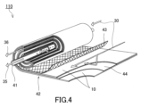
- FIG. 11 is a perspective view that illustrates a modified example of a membrane separation device provided with a separation membrane of the present invention.
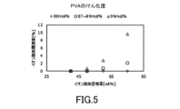
- 1 is a graph showing the relationship between the ionic liquid content and the ionic liquid leakage rate for the separation functional layers of Examples C1 to C12.
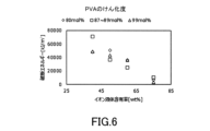
- 1 is a graph showing the relationship between the ionic liquid content and the breaking energy of the separation functional layer for the separation functional layers of Examples C1 to C12.
- 1 is a graph showing the relationship between the ionic liquid content and the breaking stress of the separation functional layer for the separation functional layers of Examples C1 to C12.
- the separation functional layer according to the first aspect of the present invention is An ionic liquid; A hydrophilic polymer A that forms a crystal structure in the ionic liquid; A polymer B different from the polymer A; Includes.
- the ionic liquid has hydrophilic or amphiphilic properties.
- the ionic liquid contains at least one selected from the group consisting of 1-ethyl-3-methylimidazolium dicyanamide and 1-ethyl-3-methylimidazolium tricyanomethanide.
- the polymer A has a hydroxyl group.
- the polymer A is bonded to the polymer B via hydrogen bonds derived from the hydroxyl groups.
- the polymer A contains polyvinyl alcohol.
- the polymer B has at least one group selected from the group consisting of an amide group and an imide group.
- the polymer B is linear.
- the polymer B contains polyvinylpyrrolidone.
- the separation functional layer according to any one of the first to ninth aspects has an ionic liquid content of 60 wt % or more.
- the separation functional layer in any one of the first to tenth aspects has a thickness of 100 ⁇ m or less.
- the separation functional layer in any one of the first to eleventh aspects has a breaking strength of 100 kPa or more.
- the permeability coefficient of carbon dioxide passing through the separation functional layer is 100 Barrer or more.
- the concentration of carbon dioxide in the mixed gas is 50 vol% under standard conditions
- the mixed gas supplied to the space adjacent to one of the surfaces has a temperature of 30°C and a pressure of 0.1 MPa
- the space adjacent to the other surface is reduced in pressure so that the pressure within the space is 0.1 MPa less than the atmospheric pressure in the measurement environment.
- a separation functional layer according to any one of the first to thirteenth aspects is used to separate an acidic gas from a gas mixture containing the acidic gas.
- the separation membrane according to the fifteenth aspect of the present invention is A separation functional layer according to any one of the first to fourteenth aspects; A porous support supporting the separation functional layer; Equipped with.
- the separation membrane according to the sixteenth aspect of the present invention is A separation functional layer; A porous support supporting the separation functional layer; Equipped with The separation functional layer contains an ionic liquid and a hydrophilic polymer A that forms a crystal structure in the ionic liquid.
- FIG. 1 is a cross-sectional view showing a schematic diagram of a separation functional layer 1 of the present embodiment.
- the separation functional layer 1 contains an ionic liquid L, a hydrophilic polymer A that forms a crystal structure in the ionic liquid L, and a polymer B different from the polymer A.
- the ionic liquid L is present, for example, in the space between the polymer A and the polymer B, and fills the space.
- the separation functional layer 1 is typically an ion gel film containing the ionic liquid L.
- the ionic liquid means a salt (ionic compound) that is liquid at 25° C.
- the separation functional layer 1 in FIG. 1 can function as a self-supporting membrane (single layer membrane).
- the separation functional layer 1 can preferentially transmit acid gases contained in a mixed gas.
- the ionic liquid L contained in the separation functional layer 1 contains, for example, at least one selected from the group consisting of imidazolium ions, pyridinium ions, ammonium ions, and phosphonium ions, and preferably contains imidazolium ions. These ions contain, for example, a substituent having one or more carbon atoms.
- substituents having one or more carbon atoms include alkyl groups having from 1 to 20 carbon atoms, cycloalkyl groups having from 3 to 14 carbon atoms, and aryl groups having from 6 to 20 carbon atoms, which may be further substituted with hydroxy groups, cyano groups, amino groups, monovalent ether groups, etc. (e.g., hydroxyalkyl groups having from 1 to 20 carbon atoms, etc.).
- ether groups include polyalkylene glycol groups such as polyethylene glycol.
- Alkyl groups having 1 to 20 carbon atoms include methyl, ethyl, n-propyl, n-butyl, n-pentyl, n-hexyl, n-heptyl, n-octyl, n-nonyl, n-decyl, n-undecyl, n-dodecyl, n-tridecyl, n-tetradecyl, n-pentadecyl, n-hexadecyl, n-heptadecyl, n-octadecyl, n-nonadecyl, and n-eicosadecy.
- Examples of such groups include silyl, i-propyl, sec-butyl, i-butyl, 1-methylbutyl, 1-ethylpropyl, 2-methylbutyl, i-pentyl, neopentyl, 1,2-dimethylpropyl, 1,1-dimethylpropyl, t-pentyl, 2-ethylhexyl, and 1,5-dimethylhexyl groups, which may be further substituted with a hydroxyl group, a cyano group, an amino group, a monovalent ether group, or the like.
- the above-mentioned alkyl group may be substituted with a cycloalkyl group.
- the number of carbon atoms of the alkyl group substituted with a cycloalkyl group is, for example, 1 or more and 20 or less.
- Examples of the alkyl group substituted with a cycloalkyl group include a cyclopropylmethyl group, a cyclobutylmethyl group, a cyclohexylmethyl group, and a cyclohexylpropyl group, which may be further substituted with a hydroxy group, a cyano group, an amino group, a monovalent ether group, etc.
- Cycloalkyl groups having 3 to 14 carbon atoms include cyclopropyl, cyclobutyl, cyclopentyl, cyclohexyl, cycloheptyl, cyclooctyl, cyclododecyl, norbornyl, bornyl, and adamantyl groups, which may be further substituted with hydroxy, cyano, amino, monovalent ether groups, etc.
- Aryl groups having 6 to 20 carbon atoms include phenyl, toluyl, xylyl, mesityl, anisyl, naphthyl, and benzyl groups, which may be further substituted with hydroxy, cyano, amino, and monovalent ether groups.
- the ionic liquid L preferably contains an imidazolium ion represented by the following formula (1).
- R 1 to R 5 are each independently a hydrogen atom or the above-mentioned substituent having 1 or more carbon atoms.
- R 1 is preferably a substituent having 1 or more carbon atoms, more preferably an alkyl group having 1 to 20 carbon atoms, even more preferably an alkyl group having 2 to 10 carbon atoms, and particularly preferably an ethyl group or an n-butyl group.
- R 3 is preferably a substituent having 1 or more carbon atoms, more preferably an alkyl group having 1 to 20 carbon atoms, even more preferably an alkyl group having 1 to 10 carbon atoms, and particularly preferably a methyl group.
- Each of R 2 , R 4 and R 5 is preferably a hydrogen atom.
- the above-mentioned ions may form salts with counter anions.
- counter anions include alkyl sulfate, tosylate, methanesulfonate, trifluoromethanesulfonate, toluenesulfonate, acetate, bis(fluorosulfonyl)imide, bis(trifluoromethanesulfonyl)imide, thiocyanate, dicyanamide, tricyanomethanide, tetracyanoborate, hexafluorophosphate, tetrafluoroborate, and halides, with dicyanamide, tetrafluoroborate, and tricyanomethanide being preferred.
- ionic liquid L examples include 1-ethyl-3-methylimidazolium bis(trifluoromethanesulfonyl)imide, 1-ethyl-3-methylimidazolium bis(fluorosulfonyl)imide, 1-ethyl-3-methylimidazolium dicyanamide, 1-butyl-3-methylimidazolium bromide, 1-butyl-3-methylimidazolium chloride, 1-butyl-3-methylimidazolium tetrafluoroborate, 1-butyl-3-methylimidazolium hexafluorophosphate, 1-butyl-3-methylimidazolium trifluoromethanesulfonate, 1-butyl-3-methylimidazolium tetrachlorofer ...hexafluorophosphate, 1-butyl-3-methylimidazolium trifluoromethanesulfonate, 1-butyl-3-methylimidazolium tetrachloro
- the ionic liquid L contained in the separation functional layer 1 is preferably hydrophilic or amphiphilic.
- the mechanical strength of the separation functional layer 1 tends to be improved.
- the ionic liquid is hydrophilic means that the ionic liquid dissolves in water in Test 1 below, and that the ionic liquid does not dissolve in isopropyl alcohol (IPA) and phase separation is observed in Test 2 below.
- the ionic liquid is amphiphilic means that the ionic liquid dissolves in water in Test 1 below, and that the ionic liquid dissolves in IPA in Test 2 below.
- Test 1 Add 0.5 g of ionic liquid to a container such as a microtube under room temperature (25°C) conditions, and then add 0.5 g of water (ion-exchanged water) to the container. Next, the container is sealed and then shaken by hand about 10 times.
- Test 2 Add 0.5 g of ionic liquid to a container such as a microtube under room temperature conditions, and then add 0.5 g of IPA to the container. Next, the container is sealed and then shaken by hand about 10 times. The container is left to stand for 1 minute, and it is visually confirmed whether the ionic liquid has dissolved in the IPA in the container.
- the ionic liquid does not dissolve in water and phase separation is confirmed in Test 1, the ionic liquid is determined to be hydrophobic.
- hydrophilic or amphiphilic ionic liquids L include 1-ethyl-3-methylimidazolium dicyanamide ([EMIM][DCA]) and 1-ethyl-3-methylimidazolium tricyanomethanide ([EMIM][TCM]).
- Ionic liquid L preferably contains at least one selected from the group consisting of [EMIM][DCA] and [EMIM][TCM], and more preferably contains [EMIM][DCA].
- [EMIM][DCA] is suitable for improving the permeability of acidic gases through separation functional layer 1.
- the content of ionic liquid L in the separation functional layer 1 is, for example, 5 wt% or more from the viewpoint of gas separation performance, and may be 30 wt% or more, 50 wt% or more, 60 wt% or more, 70 wt% or more, or even 80 wt% or more.
- the upper limit of the content of ionic liquid L is not particularly limited, and may be, for example, 95 wt% or less, or may be 90 wt% or less. By having the content of ionic liquid L be 95 wt% or less, the independence of the separation functional layer 1 tends to be easily ensured.
- the weight ratio of the ionic liquid L to the polymers (polymers A and B) is not particularly limited and is, for example, 50/50 to 90/10.
- the polymer A forms a crystal structure in the ionic liquid L.
- the polymer A crystallizes in the ionic liquid L.
- the polymer A may be entirely crystallized, but it is preferable that the polymer A is partially crystallized.
- a part of the polymer A may be crystallized, and the other part of the polymer A may be swollen by the ionic liquid L.
- the polymer A forms a crystal structure in the ionic liquid L means that when X-ray diffraction (XRD) measurement is performed on a sample containing the polymer A and the ionic liquid L at room temperature (25 ° C.), a peak derived from the crystal structure of the polymer A can be confirmed.
- the sample used for the XRD measurement is prepared by dissolving 1.3 g of the polymer A in a mixed liquid consisting of 5 g of the ionic liquid L and 10.24 g of water, drying the obtained solution at 30 ° C. for 24 hours, and then drying it at 70 ° C. for 24 hours.
- the solution can be dried, for example, using a petri dish made of polytetrafluoroethylene (PTFE).
- the crystallization of polymer A is caused, for example, by physical crosslinking of multiple polymer A molecules in ionic liquid L.
- Physical crosslinking means that multiple polymer molecules aggregate due to interactions such as intermolecular forces. It can be said that polymer A has physical crosslinking points in ionic liquid L. It should be noted that polymer A does not have, for example, a chemically crosslinked structure. Chemical crosslinking means that multiple polymer molecules are bonded to each other via covalent bonds.
- the polymer A has hydrophilicity.
- “the polymer has hydrophilicity” means that the distance Ra between the Hansen solubility parameter of the polymer and the Hansen solubility parameter of H2O is less than 19 MPa1 /2 .
- the Hansen solubility parameters are the solubility parameters introduced by Hildebrand divided into three components: the dispersion term ⁇ D, the polarization term ⁇ P, and the hydrogen bonding term ⁇ H. Details of the Hansen solubility parameters are disclosed in "Hansen Solubility Parameters; A Users Handbook (CRC Press, 2007)". The Hansen solubility parameters can be calculated using known software such as HSPiP.
- the distance Ra between the Hansen solubility parameter of the polymer and that of H2O can be calculated from the following formula (i): where ⁇ D1 , ⁇ P1 and ⁇ H1 are the dispersion term (MPa1 /2 ), polarization term (MPa1/2) and hydrogen bond term (MPa1 / 2 ) of the polymer, respectively. ⁇ D2 , ⁇ P2 and ⁇ H2 are the dispersion term (18.1 MPa1 /2 ), polarization term (17.1 MPa1 /2 ) and hydrogen bond term (16.9 MPa1 /2 ) of H2O , respectively.
- Ra ⁇ 4 ⁇ ( ⁇ D 1 - ⁇ D 2 ) 2 + ( ⁇ P 1 - ⁇ P 2 ) 2 + ( ⁇ H 1 - ⁇ H 2 ) 2 ⁇ 1/2 (i)
- the distance Ra1 between the Hansen solubility parameter of polymer A and the Hansen solubility parameter of H 2 O is preferably 18 MPa 1/2 or less, and may be 17 MPa 1/2 or less, 16 MPa 1/2 or less, 15 MPa 1/2 or less, 14 MPa 1/2 or less, 13 MPa 1/2 or less, 12 MPa 1/2 or less, 11 MPa 1/2 or less, 10 MPa 1/2 or less, or even 9 MPa 1/2 or less.
- the lower limit of the distance Ra1 is not particularly limited, and may be, for example, 3 MPa 1/2 or more, or 5 MPa 1/2 or more.
- Polymer A may be a homopolymer or a copolymer.
- copolymers include random copolymers, block copolymers, alternating copolymers, and graft copolymers.
- Polymer A preferably has no branched structure and is linear. However, polymer A may have a branched structure. In this specification, "the polymer is linear" means that the structural units contained in the polymer are arranged in a straight line without branching.
- the polymer A preferably has a polar group such as a hydroxyl group.
- the polymer A has hydrophilicity due to the polar group.
- the polymer A preferably has a hydroxyl group and is bonded to the polymer B via a hydrogen bond derived from the hydroxyl group. In this case, the separation functional layer 1 tends to have high mechanical strength.
- the polymer A preferably includes polyvinyl alcohol (PVA).
- PVA polyvinyl alcohol
- the PVA can form a crystal structure in an ionic liquid L such as [EMIM][DCA], [EMIM][TCM], etc.
- the distance Ra between the Hansen solubility parameter of PVA and the Hansen solubility parameter of H2O is about 8.1 MPa1 /2 , and it can be said that the PVA has hydrophilicity.
- the degree of saponification of the PVA as polymer A is preferably 70 mol% or more, and may be 75 mol% or more, 80 mol% or more, or even 85 mol% or more.
- the degree of saponification of the PVA may be 90 mol% or more in some cases.
- the upper limit of the degree of saponification of the PVA is not particularly limited, and is, for example, 99 mol% or less, may be 95 mol% or less, or may be 85 mol% or less in some cases.
- JIS Japanese Industrial Standards
- the weight average molecular weight of polymer A is preferably 10,000 or more, and may be 30,000 or more, or even 50,000 or more.
- the weight average molecular weight of polymer A may be 130,000 or more in some cases.
- the upper limit of the weight average molecular weight of polymer A is not particularly limited, and may be, for example, 300,000 or less, or 200,000 or less.
- the weight average molecular weight of polymer A can be calculated, for example, by measuring the molecular weight distribution of polymer A using a gel permeation chromatograph (GPC) equipped with a differential refractive index detector (RID) and using a calibration curve based on standard polystyrene from the obtained chromatogram (chart).
- GPC gel permeation chromatograph
- RID differential refractive index detector
- the content of polymer A in the separation functional layer 1 is not particularly limited, and may be, for example, 1 wt% or more, 5 wt% or more, 10 wt% or more, 15 wt% or more, or even 20 wt% or more.
- the upper limit of the content of polymer A is not particularly limited, and may be, for example, 30 wt% or less, or in some cases 20 wt% or less.
- polymer B As described above, polymer B is different from polymer A. In particular, polymer A and polymer B have different compositions. Polymer B does not form a crystal structure in ionic liquid L, for example. In other words, polymer B has a higher solubility in ionic liquid L than polymer A.
- polymer B has hydrophilicity. However, polymer B does not have to have hydrophilicity.
- the distance Ra2 between the Hansen solubility parameter of polymer B and the Hansen solubility parameter of H2O is, for example, 30 MPa1 /2 or less, preferably less than 19 MPa1 /2 .
- the lower limit of the distance Ra2 is not particularly limited, and may be, for example, 3 MPa1 /2 or more, or 5 MPa1 /2 or more.
- polymer B When polymer A has a hydroxyl group, polymer B preferably has a functional group capable of forming a hydrogen bond with the hydroxyl group. Examples of such functional groups include amide groups and imide groups. Polymer B preferably has at least one group selected from the group consisting of amide groups and imide groups, and more preferably has an amide group. As an example, polymer B may have a ring structure (lactam structure) containing an amide group.
- polymer B does not have a chemically crosslinked structure.
- This polymer B may be a homopolymer or a copolymer. Examples of the copolymer include those described above for polymer A.
- This polymer B preferably does not have a branched structure and is linear.
- An example of polymer B that does not have a chemically crosslinked structure is polyvinylpyrrolidone (PVP).
- polymer B has a chemically crosslinked structure.
- polymer B is a crosslinked product of a prepolymer.
- the prepolymer for forming the polymer B has a polymer chain containing a constituent unit derived from a monomer.
- the polymer chain is formed, for example, by radical polymerization of the monomer.
- a plurality of polymer chains are crosslinked by a crosslinking chain.
- the polymer chain and the crosslinking chain are preferably bonded by at least one bond selected from the group consisting of a hydrazone bond, an amide bond, an imide bond, a urethane bond, an ether bond, and an ester bond.
- the prepolymer may be a homopolymer, a copolymer, or a mixture thereof.
- the copolymer include those described above for polymer A.
- the prepolymer may contain a (meth)acrylic polymer.
- the (meth)acrylic polymer is a polymer having a structural unit U derived from monomer b containing a (meth)acrylic group and/or a (meth)acrylamide group.
- the (meth)acrylic polymer may have, for example, structural unit U derived from monomer b as a main component, and may be substantially composed of only structural unit U. However, the (meth)acrylic polymer may further contain other structural units other than structural unit U.
- (meth)acrylic means acrylic and/or methacrylic.
- the prepolymer contains a (meth)acrylic polymer
- the crosslinked product thereof can also be said to be a (meth)acrylic polymer.
- polymer B may be a (meth)acrylic polymer.
- the prepolymer is preferably a polymer having a crosslinking point capable of reacting with a crosslinking agent, which will be described later.
- the crosslinking point is located at either the end, main chain, or side chain of the prepolymer. From the viewpoint of obtaining a crosslinked product that is highly three-dimensionally crosslinked, the crosslinking point is preferably located at the side chain of the prepolymer.
- the prepolymer preferably has a functional group, particularly a polar group, that functions as a crosslinking point.
- a polar group means an atomic group containing atoms other than carbon and hydrogen, and typically means an atomic group containing at least one atom selected from the group consisting of N atoms and O atoms.
- Examples of polar groups include amino groups, amide groups, imide groups, morpholino groups, carboxyl groups, ester groups, hydroxyl groups, and ether groups.
- Amino groups include not only primary amino groups, but also secondary and tertiary amino groups substituted with alkyl groups, etc.
- Amide groups include (meth)acrylamide groups, acetamide groups, and pyrrolidone groups.
- Ether groups include polyalkyl ether groups such as polyethylene glycol groups and polypropylene glycol groups; epoxy groups; and vinyloxy groups.
- the prepolymer preferably contains a constituent unit derived from a polar group-containing monomer.
- the polar group-containing monomer preferably contains at least one selected from the group consisting of, for example, an amide group-containing monomer, an imide group-containing monomer, an amino group-containing monomer, an epoxy group-containing monomer, a vinyloxy group-containing monomer, a carboxyl group-containing monomer, and a hydroxyl group-containing monomer, and more preferably contains at least one selected from the group consisting of an amide group-containing monomer, an imide group-containing monomer, a vinyloxy group-containing monomer, and a carboxyl group-containing monomer.
- amide group-containing monomers examples include acrylamide, methacrylamide, N-vinylpyrrolidone, N,N-diallylacrylamide, N-methylacrylamide, N,N-dimethylacrylamide, N,N-dimethylmethacrylamide, N,N-diethylacrylamide, N,N-diethylmethacrylamide, N,N'-methylenebisacrylamide, N,N-dimethylaminopropylacrylamide, N,N-dimethylaminopropylmethacrylamide, and diacetoneacrylamide.
- imide group-containing monomers examples include N-(meth)acryloyloxysuccinimide, N-(meth)acryloyloxymethylene succinimide, and N-(meth)acryloyloxyethylene succinimide.
- amino group-containing monomers examples include aminoethyl (meth)acrylate, N,N-dimethylaminoethyl (meth)acrylate, and N,N-dimethylaminopropyl (meth)acrylate.
- epoxy group-containing monomers examples include glycidyl (meth)acrylate, methyl glycidyl (meth)acrylate, 3-ethyloxetan-3-yl (meth)acrylate, and allyl glycidyl ether.
- vinyloxy group-containing monomers examples include 2-(2-vinyloxyethoxy)ethyl (meth)acrylate, 2-vinyloxyethyl (meth)acrylate, and 4-vinyloxypropyl (meth)acrylate.
- Carboxyl group-containing monomers include (meth)acrylic acid.
- Hydroxyl group-containing monomers include 4-hydroxybutyl (meth)acrylate.
- the polar group-containing monomer may be used alone or in a mixture of two or more kinds.
- a prepolymer may be formed by copolymerizing N,N'-methylenebisacrylamide, diacetoneacrylamide (DAAm), N-acryloyloxysuccinimide (NSA), etc. together with N-methylacrylamide or N,N-dimethylacrylamide (DMAAm).
- the prepolymer may contain a constituent unit derived from N,N-dimethylacrylamide and a constituent unit derived from N-acryloyloxysuccinimide, or may be a copolymer of N,N-dimethylacrylamide and N-acryloyloxysuccinimide.
- the prepolymer may contain structural units derived from monomers other than the polar group-containing monomer.
- examples of other monomers include alkyl (meth)acrylates such as methyl (meth)acrylate and n-butyl (meth)acrylate.
- the prepolymer may contain structural units derived from n-butyl (meth)acrylate and structural units derived from (meth)acrylic acid, and may be a copolymer of n-butyl (meth)acrylate and (meth)acrylic acid.
- Polymer B contains, for example, at least one selected from the group consisting of a structure derived from a copolymer of N,N-dimethylacrylamide and N-acryloyloxysuccinimide, and a structure derived from a copolymer of n-butyl(meth)acrylate and (meth)acrylic acid, and preferably contains a structure derived from a copolymer of N,N-dimethylacrylamide and N-acryloyloxysuccinimide.
- the prepolymer may contain a structural unit that functions as a crosslinking agent, such as a structural unit derived from a polyfunctional (meth)acrylate.
- a prepolymer having this structural unit can undergo self-crosslinking.
- a polyfunctional (meth)acrylate refers to a monomer having two or more (meth)acrylic groups in one molecule. Examples of polyfunctional (meth)acrylates include trimethylolpropane tri(meth)acrylate, pentaerythritol tetra(meth)acrylate, 1,2-ethylene glycol di(meth)acrylate, 1,6-hexanediol di(meth)acrylate, and dipentaerythritol hexaacrylate.
- the weight average molecular weight (Mw) of the prepolymer is, for example, preferably 2,500 or more, more preferably 5,000 or more, and even more preferably 10,000 or more.
- the upper limit of the weight average molecular weight of the prepolymer is not particularly limited, and is, for example, 2.5 million, preferably 1 million, and more preferably 750,000.
- the weight average molecular weight of the prepolymer can be determined by the method described above for polymer A.
- the prepolymer can be obtained, for example, by polymerizing a monomer having a functional group that functions as a cross-linking point in the presence of a polymerization initiator.
- the polymerization of the monomer is preferably radical polymerization.
- the radical polymerization may be thermal polymerization or photopolymerization (for example, polymerization by ultraviolet irradiation).
- polymerization initiators As polymerization initiators, azo-based polymerization initiators, peroxide-based initiators, redox-based initiators that are a combination of peroxides and reducing agents, substituted ethane-based initiators, etc. can be used. When performing photopolymerization, various photopolymerization initiators can be used. In photopolymerization, a photosensitizer such as 2-oxoglutaric acid can also be used.
- Azo polymerization initiators include 2,2'-azobisisobutyronitrile (AIBN), 2,2'-azobis-2-methylbutyronitrile, dimethyl-2,2'-azobis(2-methylpropionate), 4,4'-azobis-4-cyanovaleric acid, azobisisovaleronitrile, 2,2'-azobis(2-amidinopropane) dihydrochloride, 2,2'-azobis[2-(5-methyl-2-imidazolin-2-yl)propane]dihydrochloride, 2,2'-azobis(2-methylpropionamidine) disulfate, and 2,2'-azobis(N,N'-dimethyleneisobutylamidine) dihydrochloride.
- AIBN 2,2'-azobisisobutyronitrile
- 2,2'-azobis-2-methylbutyronitrile dimethyl-2,2'-azobis(2-methylpropionate)
- 4,4'-azobis-4-cyanovaleric acid 4,4'-azo
- Peroxide initiators include persulfates such as potassium persulfate and ammonium persulfate; dibenzoyl peroxide, t-butyl permaleate, t-butyl hydroperoxide, di-t-butyl peroxide, t-butyl peroxybenzoate, dicumyl peroxide, 1,1-bis(t-butylperoxy)-3,3,5-trimethylcyclohexane, 1,1-bis(t-butylperoxy)cyclododecane, hydrogen peroxide, etc.
- persulfates such as potassium persulfate and ammonium persulfate
- dibenzoyl peroxide t-butyl permaleate
- t-butyl hydroperoxide di-t-butyl peroxide
- t-butyl peroxybenzoate t-butyl peroxybenzoate
- dicumyl peroxide 1,1-bis(t-butylper
- Redox initiators include combinations of peroxides and ascorbic acid (e.g., a combination of hydrogen peroxide and ascorbic acid), combinations of peroxides and iron (II) salts (e.g., a combination of hydrogen peroxide and iron (II) salts), and combinations of persulfates and sodium hydrogen sulfite.
- Substituted ethane initiators include phenyl-substituted ethane, etc.
- Photopolymerization initiators include acetophenones, ketals, benzophenones, benzoins, benzoyls, xanthones, active halogen compounds (triazines, halomethyloxadiazoles, coumarins), acridines, biimidazoles, and oxime esters.
- acetophenone-based photopolymerization initiators examples include 2,2-diethoxyacetophenone, p-dimethylaminoacetophenone, 2-hydroxy-2-methyl-1-phenyl-propan-1-one, p-dimethylaminoacetophenone, 4'-isopropyl-2-hydroxy-2-methyl-propiophenone, 1-hydroxycyclohexyl phenyl ketone, 2-benzyl-2-dimethylamino-1-(4-morpholinophenyl)-1-butanone, 2-tolyl-2-dimethylamino-1-(4-morpholinophenyl)-1-butanone, and 2-methyl-1-[4-(methylthio)phenyl]-2-morpholino-1-propanone.
- Ketal-based photopolymerization initiators include, for example, benzyl dimethyl ketal and benzyl- ⁇ -methoxyethyl acetal.
- benzophenone-based photopolymerization initiators include benzophenone, 4,4'-(bisdimethylamino)benzophenone, 4,4'-(bisdiethylamino)benzophenone, and 4,4'-dichlorobenzophenone.
- benzoin or benzoyl photopolymerization initiators examples include benzoin isopropyl ether, benzoin isobutyl ether, benzoin methyl ether, and methyl o-benzoyl benzoate.
- xanthone-based photopolymerization initiators examples include diethylthioxanthone, diisopropylthioxanthone, monoisopropylthioxanthone, and chlorothioxanthone.
- triazine-based photopolymerization initiators examples include 2,4-bis(trichloromethyl)-6-p-methoxyphenyl-s-triazine, 2,4-bis(trichloromethyl)-6-p-methoxystyryl-s-triazine, 2,4-bis(trichloromethyl)-6-(1-p-dimethylaminophenyl)-1,3-butadienyl-s-triazine, 2,4-bis(trichloromethyl)-6-biphenyl-s-triazine, 2,4-bis(trichloromethyl)-6-(p-methylbiphenyl)-s-triazine, and p-hydroxyethoxystyryl-2,6 -di(trichloromethyl)-s-triazine, methoxystyryl-2,6-di(trichloromethyl)-s-triazine, 3,4-dimethoxystyryl-2,6-
- halomethyloxadiazole photopolymerization initiators examples include 2-trichloromethyl-5-styryl-1,3,4-oxodiazole, 2-trichloromethyl-5-(cyanostyryl)-1,3,4-oxodiazole, 2-trichloromethyl-5-(naphth-1-yl)-1,3,4-oxodiazole, and 2-trichloromethyl-5-(4-styryl)styryl-1,3,4-oxodiazole.
- Examples of coumarin-based photopolymerization initiators include 3-methyl-5-amino-((s-triazin-2-yl)amino)-3-phenylcoumarin, 3-chloro-5-diethylamino-((s-triazin-2-yl)amino)-3-phenylcoumarin, and 3-butyl-5-dimethylamino-((s-triazin-2-yl)amino)-3-phenylcoumarin.
- acridine-based photopolymerization initiators examples include 9-phenylacridine and 1,7-bis(9-acridinyl)heptane.
- biimidazole-based photopolymerization initiators include lophine dimers such as 2-(o-chlorophenyl)-4,5-diphenylimidazolyl dimer, 2-(o-methoxyphenyl)-4,5-diphenylimidazolyl dimer, and 2-(2,4-dimethoxyphenyl)-4,5-diphenylimidazolyl dimer; 2-mercaptobenzimidazole; and 2,2'-dibenzothiazolyl disulfide.
- lophine dimers such as 2-(o-chlorophenyl)-4,5-diphenylimidazolyl dimer, 2-(o-methoxyphenyl)-4,5-diphenylimidazolyl dimer, and 2-(2,4-dimethoxyphenyl)-4,5-diphenylimidazolyl dimer
- 2-mercaptobenzimidazole 2-mercaptobenzimidazole
- oxime ester photopolymerization initiators examples include 1,2-octanedione, 1-[4-(phenylthio)-2-(O-benzoyloxime)], ethanone, 1-[9-ethyl-6-(2-methylbenzoyl)-9H-carbazol-3-yl]-1-(O-acetyloxime), etc.
- the polymerization initiator may be used alone or in combination of two or more.
- the polymerization initiator is preferably 2,2'-azobisisobutyronitrile.
- the amount of the polymerization initiator is not particularly limited, and is, for example, 0.1 parts by mass or more, and preferably 0.3 parts by mass or more, per 100 parts by mass of the monomer.
- the amount of the polymerization initiator is preferably 3 parts by mass or less, and more preferably 2 parts by mass or less, per 100 parts by mass of the monomer.
- the synthesis of the prepolymer may be carried out in the presence of a solvent.
- the solvent is preferably an organic solvent, for example, ketone-based organic solvents such as acetone, methyl ethyl ketone, and methyl isobutyl ketone; ester-based organic solvents such as methyl acetate, ethyl acetate, and butyl acetate; polar solvents such as dimethylformamide, dimethyl sulfoxide, and N-methyl-2-pyrrolidone; alcohol-based organic solvents such as methyl alcohol, ethyl alcohol, and isopropyl alcohol; aromatic hydrocarbon-based organic solvents such as toluene and xylene; aliphatic/alicyclic hydrocarbon-based organic solvents such as n-hexane, cyclohexane, and methylcyclohexane; cellosolve-based organic solvents such as methyl cellosolve, ethyl cellosolve,
- the method for synthesizing the prepolymer is not particularly limited, and known methods such as solution polymerization, emulsion polymerization, bulk polymerization, suspension polymerization, atom transfer radical polymerization (ATRP), and reversible addition fragmentation chain transfer polymerization (Raft) can be used, but from the viewpoint of workability, solution polymerization is preferred.
- the prepolymer may be synthesized by photopolymerization in the presence of a solvent, or by solvent-free photopolymerization, particularly UV polymerization.
- ATRP initiators include alkyl halides such as tert-butyl 2-bromoisobutyrate, methyl 2-bromoisobutyrate, 2-bromoisobutyryl bromide, ethyl 2-bromoisobutyrate, 2-hydroxyethyl 2-bromoisobutyrate, ethylene bis(2-bromoisobutyrate), 1-tris(hydroxymethyl)ethane, and pentaerythritol tetrakis(2-bromoisobutyrate).
- alkyl halides such as tert-butyl 2-bromoisobutyrate, methyl 2-bromoisobutyrate, 2-bromoisobutyryl bromide, ethyl 2-bromoisobutyrate, 2-hydroxyethyl 2-bromoisobutyrate, ethylene bis(2-bromoisobutyrate), 1-tris(hydroxymethyl)ethane, and pentaerythritol tetrakis(2-bromois
- ATRP catalyst ligands examples include 2,2'-bipyridyl, 4,4'-dimethyl-2,2'-dipyridyl, 4,4'-di-tert-butyl-2,2'-dipyridyl, 4,4'-dinonyl-2,2'-dipyridyl, N-butyl-2-pyridylmethanimine, N-octyl-2-pyridylmethanimine, N-dodecyl-N-(2-pyridylmethylene)amine, N-octadecyl-N-(2-pyridylmethylene)amine, and N,N,N',N'',N'-pentamethyldiethylenetriamine.
- metal salts for ATRP catalysts include copper(I) chloride, copper(II) chloride, copper(I) bromide, copper(II) bromide, titanium(II) chloride, titanium(III) chloride, titanium(IV) chloride, titanium(IV) bromide, and iron(II) chloride.
- RAFT agents include cyanomethyl-dodecyltrithiocarbonate, 2-(dodecylthiocarbonothioylthio)-2-methylpropionic acid, and 2-cyano-2-propyldodecyltrithiocarbonate.
- the polymerization temperature is, for example, 25 to 80°C, preferably 30 to 70°C, and more preferably 40 to 60°C.
- the polymerization temperature is preferably 10 to 60°C, more preferably 20 to 50°C, and even more preferably 20 to 40°C.
- the polymerization time is, for example, 1 to 100 hours, preferably 20 to 80 hours, more preferably 30 to 70 hours, and even more preferably 40 to 60 hours.
- the polymerization time is, for example, 0.1 to 100 hours, preferably 1 to 70 hours, more preferably 5 to 40 hours, and even more preferably 10 to 30 hours.
- the wavelength of the ultraviolet light used is not particularly limited as long as the monomer can be radically polymerized, and can be selected, for example, from a wavelength range of 200 to 550 nm, preferably 250 to 500 nm, and more preferably 300 to 400 nm.
- the intensity of the ultraviolet light is not particularly limited, but is, for example, 1 to 3000 mJ/( cm2 ⁇ s), and preferably 10 to 2000 mJ/( cm2 ⁇ s), taking into consideration the polymerization time and safety.
- Polymer B can be formed, for example, by the reaction of a prepolymer with a crosslinking agent. However, when the prepolymer contains a structural unit that functions as a crosslinking agent, polymer B can be formed by the reaction of the prepolymers themselves.
- the crosslinking agent can be appropriately selected according to the composition of the prepolymer.
- crosslinking agent examples include polyfunctional (meth)acrylate, hydrazide-based crosslinking agent, amine-based crosslinking agent, isocyanate-based crosslinking agent, epoxy-based crosslinking agent, aziridine-based crosslinking agent, melamine-based crosslinking agent, metal chelate-based crosslinking agent, metal salt-based crosslinking agent, peroxide-based crosslinking agent, oxazoline-based crosslinking agent, urea-based crosslinking agent, carbodiimide-based crosslinking agent, and coupling agent-based crosslinking agent (e.g., silane coupling agent).
- One or more types of crosslinking agents can be used in combination.
- Polymer B is preferably a crosslinked product with at least one crosslinking agent selected from the group consisting of amine-based crosslinking agents and epoxy-based crosslinking agents, and more preferably a crosslinked product with an amine-based crosslinking agent, specifically, a reaction product of a prepolymer and an amine-based crosslinking agent.
- polyfunctional (meth)acrylates examples include those mentioned above for prepolymers.
- Hydrazide crosslinking agents include, for example, isophthalic acid dihydrazide, terephthalic acid dihydrazide, phthalic acid dihydrazide, 2,6-naphthalenedicarboxylic acid dihydrazide, naphthalene acid dihydrazide, oxalic acid dihydrazide, malonic acid dihydrazide, succinic acid dihydrazide, glutamic acid dihydrazide, adipic acid dihydrazide, pimelic acid dihydrazide, suberic acid dihydrazide, azelaic acid dihydrazide, and cetearyl alcohol dihydrazide.
- polyhydrazides examples include basic acid dihydrazide, brassylic acid dihydrazide, dodecanedioic acid dihydrazide, acetonedicarboxylic acid dihydrazide, fumaric acid dihydrazide, maleic acid dihydrazide, itaconic acid dihydrazide, trimellitic acid dihydrazide, 1,3,5-benzenetricarboxylic acid dihydrazide, aconitic acid dihydrazide, and pyromellitic acid dihydrazide, with adipic acid dihydrazide being preferred.
- Amine-based crosslinking agents include, for example, aliphatic polyamines such as hexamethylenediamine, 1,12-dodecanediamine, hexamethylenediamine carbamate, N,N-dicinnamylidene-1,6-hexanediamine, tetramethylenepentamine, and hexamethylenediamine cinnamaldehyde adduct; 4,4-methylenedianiline, m-phenylenediamine, 4,4-diaminodiphenyl ether, 3,4-diaminodiphenyl ether, 4,4-(m-phenylenediisopropylidene)dianiline, and 4,4-(p-phenylenediisopropylidene)diamine.
- aliphatic polyamines such as hexamethylenediamine, 1,12-dodecanediamine, hexamethylenediamine carbamate, N,N-dicinnamylid
- Aromatic polyvalent amines such as aniline, 2,2-bis[4-(4-aminophenoxy)phenyl]propane, 4,4-diaminobenzanilide, 4,4-bis(4-aminophenoxy)biphenyl, m-xylylenediamine, p-xylylenediamine, and 1,3,5-benzenetriamine; diamines having a polyether in the main chain such as polyethylene glycol diamine, polypropylene glycol diamine, and diethylene glycol bis(3-aminopropyl)ether; and the like, with diethylene glycol bis(3-aminopropyl)ether being preferred.
- isocyanate-based crosslinking agents include aliphatic polyisocyanates such as 1,6-hexamethylene diisocyanate, 1,4-tetramethylene diisocyanate, 2-methyl-1,5-pentane diisocyanate, 3-methyl-1,5-pentane diisocyanate, and lysine diisocyanate; alicyclic polyisocyanates such as isophorone diisocyanate, cyclohexyl diisocyanate, hydrogenated tolylene diisocyanate, hydrogenated xylene diisocyanate, hydrogenated diphenylmethane diisocyanate, and hydrogenated tetramethylxylene diisocyanate; 2,4-tolylene diisocyanate, 2,6-tolylene diisocyanate, 4,4'-diphenylmethane diisocyanate, and 2,5-trimethylphenyl diisocyanate; , 4'-diphenylmethane diisocyanate
- isocyanate-based crosslinking agent a dimer or trimer, a reaction product or polymer of the exemplified isocyanate-based compounds (for example, a dimer or trimer of diphenylmethane diisocyanate, a reaction product of trimethylolpropane and tolylene diisocyanate, a reaction product of trimethylolpropane and hexamethylene diisocyanate, polymethylene polyphenylisocyanate, polyether polyisocyanate, polyester polyisocyanate), etc.
- isocyanate-based crosslinking agent a reaction product of trimethylolpropane and tolylene diisocyanate is preferred.
- Epoxy crosslinking agents include, for example, 1,3-bis(N,N-diglycidylaminomethyl)cyclohexane, N,N,N',N'-tetraglycidyl-m-xylylenediamine, diglycidylaniline, 1,6-hexanediol diglycidyl ether, neopentyl glycol diglycidyl ether, ethylene glycol diglycidyl ether, propylene glycol diglycidyl ether, polyethylene glycol diglycidyl ether, polypropylene glycol diglycidyl ether, sorbitol polyglycidyl ether, glycerol polyglycidyl ether, pentaerythritol polyglycidyl ether, polyglycerol polyglycidyl ether, sorbitan polyglycidyl ether, trimethylolpropane polyglycidyl ether, Examples of epoxy compounds having two
- Polymer B may be a (meth)acrylic polymer that does not have a crosslinked structure.
- Polymer B may contain, for example, a structural unit derived from an alkyl (meth)acrylate such as methyl (meth)acrylate or n-butyl (meth)acrylate as a main component, and may be substantially composed of only the structural unit.
- Polymer B may have the composition and structure described above for the prepolymer.
- the weight average molecular weight of polymer B is, for example, 5,000 or more, preferably 10,000 or more, more preferably 20,000 or more, and even more preferably 40,000 or more.
- the upper limit of the weight average molecular weight of polymer B is not particularly limited, and is, for example, 5 million, preferably 2 million, and more preferably 1.5 million.
- the weight average molecular weight of polymer B can be determined by the method described above for polymer A.
- the content of polymer B in the separation functional layer 1 is not particularly limited, and may be, for example, 1 wt% or more, 5 wt% or more, 10 wt% or more, or even 15 wt% or more.
- the upper limit of the content of polymer B is not particularly limited, and may be, for example, 30 wt% or less, or 20 wt% or less. In some cases, the separation functional layer 1 may not contain polymer B.
- the weight ratio of polymer A to polymer B is not particularly limited and may be, for example, 20/80 to 80/20, 40/60 to 80/20, or even 60/40 to 80/20.
- the separation functional layer 1 may further contain other components in addition to the ionic liquid L, the polymer A, and the polymer B.
- the other components include a surfactant.
- the method for producing the separation functional layer 1 includes, for example, at least one step selected from the group consisting of the following steps (i) and (ii).
- the manufacturing method including step (i) is suitable for producing a separation functional layer 1 including a polymer B that does not have a chemically crosslinked structure.
- the mixed liquid M1 further contains a solvent such as water.
- concentration of the non-volatile components (ionic liquid L, polymer A, and polymer B) in the mixed liquid M1 is not particularly limited and may be, for example, 10 wt% to 90 wt%, or 20 wt% to 50 wt%.
- the separation functional layer 1 is produced by drying a coating film produced by applying the mixed liquid M1 to a substrate.
- the substrate is typically a release liner.
- release liners include films containing resin; paper; and sheets containing metal materials such as aluminum and stainless steel. Sheets containing metal materials tend to have high heat resistance.
- the release liner is preferably a film containing resin because of its excellent surface smoothness.
- examples of polymers contained in the resin include polyolefins such as polyethylene, polypropylene, polybutene, polybutadiene, and polymethylpentene; polyesters such as polyethylene terephthalate, polybutylene terephthalate, and polyethylene naphthalate; polyvinyl chloride, vinyl chloride copolymers; polyurethane; and ethylene-vinyl acetate copolymers, with polyesters, particularly polyethylene terephthalate, being preferred.
- polyolefins such as polyethylene, polypropylene, polybutene, polybutadiene, and polymethylpentene
- polyesters such as polyethylene terephthalate, polybutylene terephthalate, and polyethylene naphthalate
- polyvinyl chloride vinyl chloride copolymers
- polyurethane polyurethane
- ethylene-vinyl acetate copolymers with polyesters, particularly polyethylene terephthalate, being preferred.
- the surface of the release liner may be subjected to a release treatment.
- the release treatment may be performed, for example, by applying a release treatment agent to the surface of the release liner.
- the release treatment agent include silicone-based release treatment agents, long-chain alkyl-based release treatment agents, fluorine-based release treatment agents, and molybdenum sulfide-based release treatment agents.
- the release treatment agents may be used alone or in combination of two or more.
- the release liner is preferably a film made of polyethylene terephthalate (PET) that has been subjected to a release treatment.
- PET polyethylene terephthalate
- the thickness of the release liner is not particularly limited, but is, for example, 5 to 100 ⁇ m, and preferably 10 to 50 ⁇ m.
- the method of applying the mixed liquid M1 to the substrate is not particularly limited, and for example, a spin coating method, a dip coating method, or the like can be used.
- the mixed liquid M1 may be applied to the substrate using an applicator or a wire bar.
- a coating film is formed by applying the mixed liquid M1 to the substrate.
- the separation functional layer 1 is produced by placing the mixed liquid M1 in a mold and then drying the mixed liquid M1.
- the mold is typically a petri dish made of PTFE.
- the drying process of the mixed liquid M1 (specifically, the coating film produced by applying the mixed liquid M1 to a substrate, or the mixed liquid M1 placed in a mold) can be carried out, for example, by leaving the mixed liquid M1 at room temperature.
- the mixed liquid M1 may also be dried by heating the mixed liquid M1.
- the drying process time is, for example, 1 hour or more, and may be 5 hours or more.
- the separation functional layer 1 that functions as a free-standing film can be obtained by peeling off the separation functional layer 1 from the substrate or mold.
- step (ii) a manufacturing method including step (ii) will be described. According to the manufacturing method including step (ii), a separation functional layer 1 including polymer B having a chemically crosslinked structure is obtained.
- the mixed liquid M2 has the same composition as the mixed liquid M1 described above, except that it contains a prepolymer and a crosslinking agent instead of polymer B.
- the separation functional layer 1 can be produced by applying the mixed liquid M2 to a substrate and then reacting the prepolymer with the crosslinking agent, or by placing the mixed liquid M2 in a mold and then reacting the prepolymer with the crosslinking agent.
- the substrate and mold can be those described above.
- the reaction between the prepolymer and the crosslinking agent can be progressed, for example, by subjecting the mixed liquid M2 (more specifically, a coating film prepared by applying the mixed liquid M2 to a substrate, or the mixed liquid M2 placed in a mold) to a heat treatment.
- the temperature of the heat treatment is not particularly limited, and may be, for example, 30°C or higher, or 50°C to 110°C.
- the time of the heat treatment is, for example, 1 minute or longer, or may be 5 minutes or longer.
- the thickness of the separation functional layer 1 is, for example, 500 ⁇ m or less, preferably 300 ⁇ m or less, may be 100 ⁇ m or less, 50 ⁇ m or less, 25 ⁇ m or less, 15 ⁇ m or less, 10 ⁇ m or less, 5.0 ⁇ m or less, or 2.0 ⁇ m or less.
- the thickness of the separation functional layer 1 may be 0.05 ⁇ m or more, or 0.1 ⁇ m or more.
- the separation functional layer 1 tends to have high mechanical strength due to the polymer A.
- the breaking strength of the separation functional layer 1 is, for example, 100 kPa or more, preferably 300 kPa or more, 500 kPa or more, 1000 kPa or more, 1500 kPa or more, 2000 kPa or more, 2500 kPa or more, or even 3000 kPa or more.
- the upper limit of the breaking strength of the separation functional layer 1 is not particularly limited, and is, for example, 10000 kPa or less.
- the tensile test of the separation functional layer 1 can be performed in accordance with the provisions of JIS K7161-1:2014. In this specification, the breaking strength means the tensile breaking stress ⁇ b defined in JIS K7161-1:2014.
- the separation functional layer 1 also tends to suppress leakage of the ionic liquid L.
- the ratio (leakage rate) of the weight of the ionic liquid L leaking from the separation functional layer 1 when a compression test is performed on the separation functional layer 1 to the weight of the ionic liquid L contained in the separation functional layer 1 may be, for example, 5.0 wt% or less, 3.0 wt% or less, or even 2.0 wt% or less.
- the ionic liquid L may not substantially leak from the separation functional layer 1.
- the compression test is performed by applying a compressive load of 1.16 MPa to the separation functional layer 1 for 2 minutes. At this time, the direction in which the compressive load is applied is aligned with the thickness direction of the separation functional layer 1.
- the compression test is performed at room temperature (25°C).
- the separation functional layer 1 can preferentially permeate the acidic gas contained in the mixed gas.
- the permeation rate T1 of carbon dioxide through the separation functional layer 1 is, for example, 0.1 GPU or more, and may be 0.3 GPU or more, 0.4 GPU or more, 0.5 GPU or more, 0.6 GPU or more, 0.7 GPU or more, 0.8 GPU or more, 0.9 GPU or more, or even 1.0 GPU or more.
- the upper limit of the permeation rate T1 is not particularly limited, and is, for example, 1000 GPU or less, and may be 100 GPU or less in some cases, or may be 10 GPU or less.
- GPU means 10 -6 cm 3 (STP)/(sec cm 2 cmHg).
- the carbon dioxide permeability coefficient C1 for the separation functional layer 1 is, for example, 100 Barrer or more, preferably 150 Barrer or more, 170 Barrer or more, 200 Barrer or more, 230 Barrer or more, 250 Barrer or more, 270 Barrer or more, or even 300 Barrer or more.
- the upper limit of the permeability coefficient C1 is not particularly limited, and is, for example, 1000 Barrer.
- Barrer means 10-10 cm3 (STP) cm/(sec cm2 cmHg).
- cm3 (STP) means the volume of carbon dioxide at 1 atmosphere and 0°C.
- the permeability coefficient C1 (Barrer) is the value obtained by multiplying the permeability rate T1 (GPU) by the thickness ( ⁇ m) of the separation functional layer 1.
- the permeation rate T1 and the permeation coefficient C1 can be calculated by the following method. First, a mixed gas consisting of carbon dioxide and hydrogen is supplied to the space adjacent to one side of the separation functional layer 1, and the space adjacent to the other side of the separation functional layer 1 is depressurized. This results in a permeating fluid that has permeated the separation functional layer 1. The weight of the permeating fluid, as well as the volume ratio of carbon dioxide and the volume ratio of hydrogen in the permeating fluid are measured. The permeation rate T1 and the permeation coefficient C1 can be calculated from the measurement results. In the above operation, the concentration of carbon dioxide in the mixed gas is 50 vol% under standard conditions (0°C, 101 kPa).
- the mixed gas supplied to the space adjacent to one side of the separation functional layer 1 has a temperature of 30°C and a pressure of 0.1 MPa.
- the space adjacent to the other side of the separation functional layer 1 is depressurized so that the pressure in the space is 0.1 MPa lower than the atmospheric pressure in the measurement environment.
- the separation factor ⁇ 1 of carbon dioxide relative to hydrogen in the separation functional layer 1 is not particularly limited, and is, for example, 5 or more, and is preferably 6 or more, 7 or more, 8 or more, 9 or more, or even 10 or more.
- the upper limit of the separation factor ⁇ 1 is not particularly limited, and is, for example, 50 or less.
- the use of the separation functional layer 1 of this embodiment includes the use of separating an acidic gas from a mixed gas containing an acidic gas.
- the acidic gas in the mixed gas include carbon dioxide, hydrogen sulfide, carbonyl sulfide, sulfur oxides (SOx), hydrogen cyanide, and nitrogen oxides (NOx), and preferably carbon dioxide.
- the mixed gas contains other gases other than the acidic gas. Examples of the other gases include non-polar gases such as hydrogen and nitrogen, and inert gases such as helium, and preferably hydrogen.
- the separation functional layer 1 of this embodiment is suitable for separating carbon dioxide from a mixed gas containing carbon dioxide and hydrogen.
- the use of the separation functional layer 1 is not limited to the use of separating an acidic gas from the above-mentioned mixed gas.
- the separation membrane 10 of the present embodiment includes the above-mentioned separation functional layer 1, and further includes, for example, a porous support 3.
- the porous support 3 supports the separation functional layer 1.
- the separation membrane 10 may further include an intermediate layer 2 disposed between the separation functional layer 1 and the porous support 3.
- the intermediate layer 2 is in direct contact with, for example, both the separation functional layer 1 and the porous support 3.
- the separation functional layer 1 of the separation membrane 10 may not contain the polymer B in some cases.
- the present invention provides A separation functional layer 1; A porous support 3 supporting a separation functional layer 1; Equipped with The separation functional layer 1 provides a separation membrane 10 containing an ionic liquid L and a hydrophilic polymer A that forms a crystal structure in the ionic liquid L.
- the intermediate layer 2 includes, for example, a resin and further includes nanoparticles dispersed in the resin (matrix).
- the nanoparticles may be separated from each other in the matrix or may be partially aggregated.
- the intermediate layer 2 may not include nanoparticles and may be substantially composed of a resin.
- the material of the matrix is not particularly limited, and examples thereof include silicone resins such as polydimethylsiloxane; fluororesins such as polytetrafluoroethylene; epoxy resins such as polyethylene oxide; polyimide resins; polysulfone resins; polyacetylene resins such as polytrimethylsilylpropyne and polydiphenylacetylene; and polyolefin resins such as polymethylpentene.
- the matrix preferably contains a silicone resin.
- the nanoparticles may contain an inorganic material or an organic material.
- inorganic materials contained in the nanoparticles include silica, titania, and alumina. It is preferable that the nanoparticles contain silica.
- the nanoparticles may have a surface modified with a modifying group containing a carbon atom.
- the nanoparticles having a surface modified with this modifying group have excellent dispersibility in a matrix.
- the nanoparticles are, for example, silica nanoparticles having a surface modified with a modifying group.
- the modifying group further contains, for example, a silicon atom.
- the surface modified with the modifying group is, for example, represented by the following formulas (I) to (III).
- R 6 to R 11 in formulae (I) to (III) are each independently a hydrocarbon group which may have a substituent.
- the number of carbon atoms in the hydrocarbon group is not particularly limited as long as it is 1 or more.
- the number of carbon atoms in the hydrocarbon group may be, for example, 25 or less, 20 or less, 10 or less, or 5 or less. In some cases, the number of carbon atoms in the hydrocarbon group may be more than 25.
- the hydrocarbon group may be a linear or branched chain hydrocarbon group, or an alicyclic or aromatic cyclic hydrocarbon group. In a preferred embodiment, the hydrocarbon group is a linear or branched alkyl group having 1 to 8 carbon atoms.
- the hydrocarbon group is, for example, a methyl group or an octyl group, and is preferably a methyl group.
- substituent of the hydrocarbon group include an amino group and an acyloxy group.
- acyloxy group include a (meth)acryloyloxy group.
- the hydrocarbon group which may have the substituents described above for R 6 to R 11 in formulas (I) to (III) is represented by the following formula (IV): Nanoparticles having a surface modified with a modifying group containing a hydrocarbon group represented by formula (IV) are suitable for improving the permeation rate of acidic gases through separation membrane 10.
- R 12 is an alkylene group having 1 to 5 carbon atoms which may have a substituent.
- the alkylene group may be linear or branched.
- Examples of the alkylene group include a methylene group, an ethylene group, a propane-1,3-diyl group, a butane-1,4-diyl group, and a pentane-1,5-diyl group, and preferably a propane-1,3-diyl group.
- the substituent of the alkylene group include an amide group and an amino alkylene group.
- R 13 is an alkyl group or aryl group having 1 to 20 carbon atoms which may have a substituent.
- the alkyl group may be linear or branched.
- Examples of the alkyl group and aryl group include those described above for ionic liquid L.
- Examples of the substituents of the alkyl group and aryl group include an amino group and a carboxyl group.
- R 13 is a 3,5-diaminophenyl group.
- the surface modified with the modifying group is preferably represented by the following formula (V).
- the modifying group is not limited to the structures shown in formulas (I) to (III).
- the modifying group may contain a polymer chain having a polyamide structure or a polydimethylsiloxane structure in place of R 6 to R 11 in formulas (I) to (III).
- the polymer chain is directly bonded to a silicon atom.
- the shape of the polymer chain may be, for example, linear, dendrimer, or hyperbranched.
- the method for modifying the surface of the nanoparticles with the modifying group is not particularly limited.
- the surface of the nanoparticles can be modified by reacting the hydroxyl groups present on the surface of the nanoparticles with a known silane coupling agent.
- the modifying group contains a polyamide structure
- the surface of the nanoparticles can be modified by, for example, the method disclosed in JP 2010-222228 A.
- the average particle size of the nanoparticles is not particularly limited as long as it is on the nanometer order ( ⁇ 1000 nm), and is, for example, 100 nm or less, preferably 50 nm or less, and more preferably 20 nm or less.
- the lower limit of the average particle size of the nanoparticles is, for example, 1 nm.
- the average particle size of the nanoparticles can be specified, for example, by the following method. First, the cross section of the intermediate layer 2 is observed with a transmission electron microscope. In the obtained electron microscope image, the area of a specific nanoparticle is calculated by image processing. The diameter of a circle having the same area as the calculated area is regarded as the particle size of the specific nanoparticle (particle diameter).
- the particle sizes of an arbitrary number of nanoparticles are calculated, and the average of the calculated values is regarded as the average particle size of the nanoparticles.
- the shape of the nanoparticles is not particularly limited, and may be spherical, ellipsoidal, scaly, or fibrous.
- the nanoparticle content in the intermediate layer 2 is, for example, 5 wt% or more, preferably 10 wt% or more, and more preferably 15 wt% or more.
- the upper limit of the nanoparticle content in the intermediate layer 2 is not particularly limited, and is, for example, 30 wt%.
- the thickness of the intermediate layer 2 is not particularly limited, and is, for example, less than 50 ⁇ m, preferably 40 ⁇ m or less, and more preferably 30 ⁇ m or less.
- the lower limit of the thickness of the intermediate layer 2 is not particularly limited, and is, for example, 1 ⁇ m.
- the intermediate layer 2 is, for example, a layer having a thickness of less than 50 ⁇ m.
- the porous support 3 supports the separation function layer 1 via the intermediate layer 2.
- the porous support 3 include nonwoven fabrics, porous polytetrafluoroethylene, aromatic polyamide fibers, porous metals, sintered metals, porous ceramics, porous polyesters, porous nylons, activated carbon fibers, latex, silicone, silicone rubber, permeable (porous) polymers including at least one selected from the group consisting of polyvinyl fluoride, polyvinylidene fluoride, polyurethane, polypropylene, polyethylene, polystyrene, polycarbonate, polysulfone, polyether ether ketone, polyacrylonitrile, polyimide, and polyphenylene oxide, metal foams having open or closed cells, polymer foams having open or closed cells, silica, porous glass, and mesh screens.
- the porous support 3 may be a combination of two or more of these.
- the porous support 3 has an average pore size of, for example, 0.01 to 0.4 ⁇ m.
- the thickness of the porous support 3 is not particularly limited, and is, for example, 10 ⁇ m or more, preferably 20 ⁇ m or more, and more preferably 50 ⁇ m or more.
- the thickness of the porous support 3 is, for example, 300 ⁇ m or less, preferably 200 ⁇ m or less, and more preferably 150 ⁇ m or less.
- the separation membrane 10 can be produced, for example, by the following method.
- a coating liquid containing the material of the intermediate layer 2 is applied onto the porous support 3 to form a coating film.
- the method of applying the coating liquid is not particularly limited, and for example, a spin coating method, a dip coating method, or the like can be used.
- the coating liquid may be applied using a wire bar or the like.
- the coating film is dried to form the intermediate layer 2.
- the coating film can be dried, for example, under heating conditions.
- the heating temperature of the coating film is, for example, 50° C. or higher.
- the heating time of the coating film is, for example, 1 minute or more, and may be 5 minutes or more.
- the surface of the intermediate layer 2 may be subjected to an easy-adhesion treatment as necessary.
- Examples of the easy-adhesion treatment include surface treatments such as application of an undercoat agent, corona discharge treatment, and plasma treatment.
- the mixed liquid M1 (or mixed liquid M2) for forming the separation functional layer 1 is applied onto the intermediate layer 2 in the laminate of the porous support 3 and the intermediate layer 2.
- the separation functional layer 1 is formed on the intermediate layer 2, and the separation membrane 10 can be obtained.
- the strength of the separation functional layer 1 has been improved. Therefore, the separation functional layer 1 can also be formed on the intermediate layer 2 by a roll-to-roll method.
- the method for producing the separation membrane 10 is not limited to the above method.
- the separation membrane 10 may be produced by the following method. First, a separation functional layer 1 formed on a substrate such as a release liner is prepared by the above method. Next, a coating liquid containing the material for the intermediate layer 2 is applied onto the separation functional layer 1 and dried to form the intermediate layer 2. The laminate of the intermediate layer 2 and the separation functional layer 1 is transferred to the porous support 3. This results in the separation membrane 10.
- the separation membrane 10 is typically a flat membrane.
- the separation membrane 10 may have a shape other than a flat membrane, for example, a hollow fiber membrane.
- the separation membrane 10 as a hollow fiber membrane may include a separation function layer 1 and a porous support 3, but may not include an intermediate layer 2.
- the separation membrane 10 of this embodiment can preferentially permeate the acidic gas contained in the mixed gas due to the separation functional layer 1.
- the permeation rate T2 of carbon dioxide permeating the separation membrane 10 is, for example, 50 GPU or more, and may be 80 GPU or more, 100 GPU or more, 120 GPU or more, 150 GPU or more, or even 180 GPU or more.
- the upper limit of the permeation rate T2 is not particularly limited and is, for example, 1000 GPU or less.
- the permeation rate T2 can be measured by the method described above for the permeation rate T1 and permeation coefficient C1 of the separation functional layer 1.
- a mixed gas consisting of carbon dioxide and hydrogen is supplied, for example, to a space adjacent to the main surface 11 on the separation functional layer side of the separation membrane 10. Furthermore, the pressure in the space adjacent to the main surface 12 on the porous support side of the separation membrane 10 is reduced.
- the separation coefficient ⁇ 2 of carbon dioxide relative to hydrogen of the separation membrane 10 is not particularly limited, and is, for example, 5 or more, and preferably 6 or more, 7 or more, 8 or more, 9 or more, or even 10 or more.
- the upper limit of the separation coefficient ⁇ 2 is not particularly limited, and is, for example, 50 or less.
- the separation coefficient ⁇ 2 can be calculated by the method described above for the separation coefficient ⁇ 1.
- the membrane separation device 100 of this embodiment includes a separation membrane 10 and a tank 20.
- a separation functional layer 1 alone instead of the separation membrane 10.
- the tank 20 includes a first chamber 21 and a second chamber 22.
- the separation membrane 10 is disposed inside the tank 20. Inside the tank 20, the separation membrane 10 separates the first chamber 21 and the second chamber 22.
- the separation membrane 10 extends from one to the other of a pair of walls of the tank 20.
- the first chamber 21 has an inlet 21a and an outlet 21b.
- the second chamber 22 has an outlet 22a.
- Each of the inlet 21a, the outlet 21b, and the outlet 22a is, for example, an opening formed in the wall surface of the tank 20.
- Membrane separation using the membrane separation device 100 is performed, for example, by the following method.
- the mixed gas 30 containing the acidic gas is supplied to the first chamber 21 through the inlet 21a.
- the concentration of the acidic gas in the mixed gas 30 is not particularly limited, and under standard conditions, it is, for example, 0.01 vol% (100 ppm) or more, preferably 1 vol% or more, more preferably 10 vol% or more, even more preferably 30 vol% or more, and particularly preferably 50 vol% or more.
- the upper limit of the concentration of the acidic gas in the mixed gas 30 is not particularly limited, and under standard conditions, it is, for example, 90 vol%.
- the pressure inside the first chamber 21 may be increased by supplying the mixed gas 30.
- the membrane separation device 100 may further include a pump (not shown) for increasing the pressure of the mixed gas 30.
- the pressure of the mixed gas 30 supplied to the first chamber 21 is, for example, 0.1 MPa or more, preferably 0.3 MPa or more.
- the second chamber 22 may be depressurized while the mixed gas 30 is being supplied to the first chamber 21.
- the membrane separation device 100 may further include a pump (not shown) for depressurizing the second chamber 22.
- the second chamber 22 may be depressurized so that the space within the second chamber 22 is reduced by, for example, 10 kPa or more, preferably 50 kPa or more, and more preferably 100 kPa or more, relative to the atmospheric pressure in the measurement environment.
- a permeating fluid 35 having a higher acid gas content than the mixed gas 30 can be obtained on the other side of the separation membrane 10. That is, the permeating fluid 35 is supplied to the second chamber 22.
- the permeating fluid 35 contains, for example, an acid gas as a main component. However, the permeating fluid 35 may contain small amounts of other gases besides the acid gas.
- the permeating fluid 35 is discharged to the outside of the tank 20 through the outlet 22a.
- the concentration of acid gas in the mixed gas 30 gradually decreases from the inlet 21a to the outlet 21b of the first chamber 21.
- the mixed gas 30 (non-permeating fluid 36) treated in the first chamber 21 is discharged to the outside of the tank 20 through the outlet 21b.
- the membrane separation device 100 of this embodiment is suitable for a flow-through (continuous) membrane separation method.
- the membrane separation device 100 of this embodiment may also be used for a batch-type membrane separation method.
- the membrane separation device 100 may be a spiral-type membrane element, a hollow fiber membrane element, or the like.
- Fig. 4 shows a spiral-type membrane element.
- the membrane separation device 110 in Fig. 4 includes a central tube 41 and a laminate 42.
- the laminate 42 includes a separation membrane 10.
- the laminate 42 may include a separation functional layer 1 alone instead of the separation membrane 10.
- the central tube 41 has a cylindrical shape. A plurality of holes are formed on the surface of the central tube 41 to allow the permeation fluid 35 to flow into the interior of the central tube 41.
- materials for the central tube 41 include resins such as acrylonitrile butadiene styrene copolymer resin (ABS resin), polyphenylene ether resin (PPE resin), and polysulfone resin (PSF resin); and metals such as stainless steel and titanium.
- the inner diameter of the central tube 41 is, for example, in the range of 20 to 100 mm.
- the laminate 42 further includes a feed-side flow path material 43 and a permeate-side flow path material 44 in addition to the separation membrane 10.
- the laminate 42 is wound around the central tube 41.
- the membrane separation device 110 may further include an exterior material (not shown).
- the supply-side flow passage material 43 and the permeate-side flow passage material 44 can be, for example, a resin net made of polyphenylene sulfide (PPS) or ethylene-chlorotrifluoroethylene copolymer (ECTFE).
- PPS polyphenylene sulfide
- ECTFE ethylene-chlorotrifluoroethylene copolymer
- the membrane separation device 110 stress is applied to the separation membrane 10 in contact with the supply side flow path material 43 and the permeation side flow path material 44.
- the strength of the separation functional layer 1 tends to be high, so the characteristics of the separation membrane 10 are hardly deteriorated by the above stress.
- the separation coefficient ⁇ 2 of the separation membrane 10 hardly decreases before and after the membrane separation device 110 is fabricated.
- Membrane separation using the membrane separation device 110 is performed, for example, by the following method.
- the permeating fluid 35 that has permeated the separation membrane 10 of the stack 42 moves into the inside of the central tube 41.
- the permeating fluid 35 is discharged to the outside through the central tube 41.
- the mixed gas 30 (non-permeating fluid 36) that has been treated by the membrane separation device 110 is discharged to the outside from the other end of the rolled stack 42. This allows the acid gas to be separated from the mixed gas 30.
- Example A1 First, 4 g of polyvinyl alcohol (PVA, manufactured by Sigma Aldrich, weight average molecular weight 85000-124000, saponification degree 87-89 mol%) as polymer A was added to 36 g of water and heated to 90°C. The mixture was stirred until the PVA was completely dissolved to prepare a PVA aqueous solution. Next, 1.6 g of polyvinylpyrrolidone (PVP, manufactured by Sigma Aldrich, weight average molecular weight 360000) as polymer B was added to 38.4 g of water. The mixture was stirred at 25°C until the PVP was completely dissolved to prepare a PVP aqueous solution.
- PVA polyvinyl alcohol
- PVP polyvinylpyrrolidone
- Example A1 The resulting mixture was then placed in a PTFE mold (petri dish) and dried in a thermostatic chamber at 30°C for 48 hours, and then dried on a hot plate at 70°C for 3 hours. This resulted in the separation functional layer (freestanding membrane) of Example A1.
- Examples A2 to A3 Separation functional layers (self-supporting membranes) of Examples A2 and A3 were obtained in the same manner as in Example A1, except that the weight ratio of ionic liquid L to polymers A and B was changed as shown in Table 1.
- Example A4 A separation functional layer (self-supporting membrane) of Example A4 was obtained in the same manner as in Example A1, except that polymer B was not used and the weight ratio of ionic liquid L to polymer A was 75/25.
- Example A5 An attempt was made to prepare a separation functional layer (self-supporting membrane) using the same method as in Example A1, except that polymer A was not used and the weight ratio of ionic liquid L to polymer B was 75/25. However, the mixed liquid did not solidify sufficiently, and a separation functional layer could not be obtained.
- the carbon dioxide permeation rate T1, the carbon dioxide permeation coefficient C1, and the separation coefficient ⁇ 1 (CO 2 /H 2 ) of carbon dioxide relative to hydrogen were measured by the following method using a differential pressure gas permeation tester (GTR Tech, GTR-31AHND).
- GTR Tech, GTR-31AHND a differential pressure gas permeation tester
- the separation functional layer cut into a square of about 3 cm was set in a metal cell and sealed with an O-ring to prevent leakage.
- a mixed gas was injected into the metal cell so that the mixed gas contacted one main surface of the separation functional layer.
- the mixed gas was substantially composed of carbon dioxide and hydrogen.
- the concentration of carbon dioxide in the mixed gas was 50 vol% under standard conditions.
- the mixed gas injected into the metal cell had a temperature of 30° C. and a pressure of 0.1 MPa.
- the space in the metal cell adjacent to the other main surface of the separation functional layer was depressurized by a vacuum pump. At this time, the pressure in this space was depressurized so that the pressure in the space was 0.1 MPa lower than the atmospheric pressure in the measurement environment.
- a permeated fluid was obtained from the other main surface of the separation functional layer.
- the permeation rate T1, permeation coefficient C1, and separation coefficient ⁇ 1 were calculated based on the composition and weight of the obtained permeated fluid. The results are shown in Table 1.
- Example A4 As can be seen from Table 1, the separation functional layers of Examples A1 to A3, which contain polymer A and polymer B, had better carbon dioxide permeability than Example A4.
- Example B1 First, an ultrafiltration membrane (NITTO DENKO CORPORATION, NTU-3175M) was prepared as a porous support. Next, a 6 wt% decane solution of silicone resin (Momentive Performance Materials, Inc., YSR3022) was prepared, and a catalyst (Momentive Performance Materials, Inc., YC6831) was added as 1% of the silicone resin solid content, and acetylacetone (FUJIFILM Wako Pure Chemical Industries, Ltd.) was added as a hardening retarder at 3% of the silicone resin solid content. The obtained solution was applied onto the porous support. The application was performed using a bar coater under the condition of a coating thickness of 68.6 ⁇ m.
- the obtained coating film was dried at 130 ° C. for 5 minutes. This resulted in a laminate of a porous support and an intermediate layer. The thickness of the intermediate layer was about 1 ⁇ m. Furthermore, the laminate was subjected to corona treatment at an output of 0.1 kW.
- a PVA aqueous solution and a PVP aqueous solution were prepared by the same method as in Example A1.
- 1.5 g of a PVA aqueous solution, 1.5 g of a PVP aqueous solution, 0.63 g of 1-ethyl-3-methylimidazolium dicyanamide ([EMIM][DCA]) as ionic liquid L, and 0.018 g of a surfactant (AGC Seimi Chemical Co., Ltd., Surflon S-243) were mixed and thoroughly stirred until completely dissolved. This resulted in a mixed solution.
- the resulting mixed solution was applied onto the above-mentioned laminate to obtain a coating film.
- the mixed solution was applied using a spin coater at 1000 rpm.
- the coating film was left at 25°C for one day or more and dried to produce a separation functional layer. This resulted in the separation membrane (composite membrane) of Example B1.
- Examples B2 to B5 Separation membranes (composite membranes) of Examples B2 to B5 were obtained in the same manner as in Example B1, except that the ionic liquid L and the weight ratios of the polymers A and B were changed as shown in Table 2.
- Example B6 The separation membrane (composite membrane) of Example B6 was obtained in the same manner as in Example B1, except that 1-ethyl-3-methylimidazolium tricyanomethanide ([EMIM][TCM]) was used as the ionic liquid L.
- [EMIM][TCM] 1-ethyl-3-methylimidazolium tricyanomethanide
- Example B7 A separation membrane (composite membrane) of Example B7 was obtained in the same manner as in Example B1, except that polymer B was not used and the weight ratio of ionic liquid L to polymer A was 75/25.
- Example B8 First, a reflux tube was attached to the three-neck flask, and the synthesis apparatus was assembled. A vacuum pump and a N2 cylinder were connected to the three-way cock. A total of five sets of nitrogen replacement were performed, with one set being a vacuum and nitrogen supply operation once every two minutes. After nitrogen replacement, 1,4-dioxane was added to the three-neck flask using a glass syringe.
- N,N-dimethylacrylamide (DMAAm) (14.6 g, 147.28 mmol
- N-acryloyloxysuccinimide (1.32 g, 7.80 mmol)
- AIBN 2,2'-azobisisobutyronitrile
- the resulting mixture was added to the three-neck flask using a syringe.
- the solution in the three-neck flask was stirred with a stirrer for about 10 minutes.
- the reflux condenser was connected to a cooling device, and polymerization was carried out under reflux for 24 hours using an oil bath set at 60°C.
- the solution after polymerization was transferred to a recovery flask and evaporatively treated at 60°C for 30 minutes or more to remove 1,4-dioxane from the solution. THF was then added to the recovery flask to dissolve the white solid. Next, the resulting solution was added dropwise to hexane cooled to -10°C using a dropper while stirring to obtain a precipitate. The precipitate was treated in a 30°C thermostatic bath under a vacuum atmosphere for 24 hours to obtain a prepolymer (poly(DMAAm-co-NSA)).
- polyvinyl alcohol (PVA, manufactured by Sigma Aldrich, weight average molecular weight 85,000-124,000, degree of saponification 87-89 mol%) as polymer A was added to water and heated to 90°C. The mixture was stirred until the PVA was completely dissolved, preparing a PVA aqueous solution.
- the above prepolymer (poly(DMAAm-co-NSA)) was added to this PVA aqueous solution and stirred for 1 hour.
- 1-ethyl-3-methylimidazolium dicyanamide ([EMIM][DCA]) as ionic liquid L was added and stirred for 30 minutes.
- Diethylene glycol bis(3-aminopropyl) ether was added as a crosslinking agent to the resulting mixture and stirred for 3 minutes. This produced a mixture for forming a separation functional layer.
- Example B8 the obtained mixture was applied onto the laminate of the porous support and the intermediate layer to obtain a coating film.
- the laminate of the porous support and the intermediate layer used was that described above in Example B1 (a laminate subjected to corona treatment at an output of 0.1 kW).
- the mixture was applied using a spin coater at 1000 rpm.
- the coating film was then left at 25°C for at least one day and dried. This allowed the reaction between the prepolymer and the crosslinking agent to proceed, forming polymer B, thereby obtaining the separation membrane (composite membrane) of Example B8.
- the weight ratio of ionic liquid L to polymer (polymers A and B) was 75/25
- the weight ratio (A/B) of polymer A to polymer B was 71/29.
- Example B9 An attempt was made to prepare a separation membrane (composite membrane) by the same method as in Example B1, except that polymer A was not used and the weight ratio of ionic liquid L to polymer B was 75/25. However, the mixed liquid did not solidify sufficiently, and a separation functional layer was not formed.
- Example C1 The separation functional layer (self-supporting membrane) of Example C1 was obtained by the same method as Example A4, except that polyvinyl alcohol a1 (PVA, manufactured by Tokyo Chemical Industry Co., Ltd., polymerization degree 2000, weight average molecular weight 88000, saponification degree 80 mol%) was used as polymer A and the weight ratio of ionic liquid L to polymer A was 40/60.
- PVA polyvinyl alcohol a1
- Example C2 A separation functional layer (self-supporting membrane) of Example C2 was obtained in the same manner as in Example C1, except that polyvinyl alcohol a2 (PVA, manufactured by Sigma Aldrich, weight average molecular weight 85,000-124,000, saponification degree 87-89 mol%) was used as polymer A.
- PVA polyvinyl alcohol a2
- Example C3 A separation functional layer (self-supporting membrane) of Example C3 was obtained in the same manner as in Example C1, except that polyvinyl alcohol a3 (PVA, manufactured by Sigma Aldrich, weight average molecular weight 85,000-124,000, saponification degree 99 mol%) was used as polymer A.
- PVA polyvinyl alcohol a3
- Examples C4 to C12 Separation functional layers (self-supporting membranes) of Examples C4 to C12 were obtained in the same manner as in Example C1, except that the type of polymer A and the weight ratio of ionic liquid L to polymer A were changed as shown in Table 3.
- Figures 5 to 7 are graphs showing the relationship between the ionic liquid content and each characteristic for the separation functional layers of Examples C1 to C12. As can be seen from Table 3 and Figures 5 to 7 (particularly Figure 5), when PVA with a low degree of saponification is used, leakage of ionic liquid tends to be more suppressed in the separation functional layer. Furthermore, these results also show that the degree of saponification of PVA does not have a significant effect on the mechanical strength of the separation functional layer.
- the separation functional layer and separation membrane of the present embodiment are suitable for separating an acidic gas from a mixed gas containing the acidic gas.
- the separation functional layer and separation membrane of the present embodiment are suitable for separating carbon dioxide from off-gas of a chemical plant or thermal power plant.
Landscapes
- Chemical & Material Sciences (AREA)
- Chemical Kinetics & Catalysis (AREA)
- Health & Medical Sciences (AREA)
- Medicinal Chemistry (AREA)
- Polymers & Plastics (AREA)
- Organic Chemistry (AREA)
- Separation Using Semi-Permeable Membranes (AREA)
Abstract
Description
イオン液体と、
前記イオン液体中で結晶構造を形成する親水性のポリマーAと、
前記ポリマーAとは異なるポリマーBと、
を含む、分離機能層を提供する。
上記の分離機能層と、
前記分離機能層を支持している多孔性支持体と、
を備えた、分離膜を提供する。
分離機能層と、
前記分離機能層を支持している多孔性支持体と、
を備え、
前記分離機能層は、イオン液体と、前記イオン液体中で結晶構造を形成する親水性のポリマーAとを含む、分離膜を提供する。
イオン液体と、
前記イオン液体中で結晶構造を形成する親水性のポリマーAと、
前記ポリマーAとは異なるポリマーBと、
を含む。
ここで、前記混合気体における前記二酸化炭素の濃度は、標準状態で50vol%であり、前記一方の面に隣接する空間に供給される前記混合気体は、温度が30℃であり、圧力が0.1MPaであり、前記他方の面に隣接する空間は、当該空間内の圧力が測定環境における大気圧に対して0.1MPa小さくなるように減圧されている。
第1~第14態様のいずれか1つにかかる分離機能層と、
前記分離機能層を支持している多孔性支持体と、
を備える。
分離機能層と、
前記分離機能層を支持している多孔性支持体と、
を備え、
前記分離機能層は、イオン液体と、前記イオン液体中で結晶構造を形成する親水性のポリマーAとを含む。
図1は、本実施形態の分離機能層1を模式的に示す断面図である。分離機能層1は、イオン液体Lと、イオン液体L中で結晶構造を形成する親水性のポリマーAと、ポリマーAとは異なるポリマーBと、を含んでいる。分離機能層1において、イオン液体Lは、例えば、ポリマーA及びポリマーBの間の空間に存在し、当該空間を満たしている。分離機能層1は、典型的には、イオン液体Lを含むイオンゲル膜である。本明細書において、イオン液体は、25℃で液体の塩(イオン性化合物)を意味する。
分離機能層1に含まれるイオン液体Lは、例えば、イミダゾリウムイオン、ピリジニウムイオン、アンモニウムイオン及びホスホニウムイオンからなる群より選ばれる少なくとも1つを含み、好ましくはイミダゾリウムイオンを含む。これらのイオンは、例えば、炭素数1以上の置換基を含む。

試験1:室温(25℃)の条件下でイオン液体0.5gをミクロチューブなどの容器に加え、さらに、当該容器に水(イオン交換水)0.5gを加える。次に、容器を密閉してから、当該容器を10回程度手で振る。容器を1分間静置し、容器内において、イオン液体が水に溶解しているかどうかを目視で確認する。
試験2:室温の条件下でイオン液体0.5gをミクロチューブなどの容器に加え、さらに、当該容器にIPA0.5gを加える。次に、容器を密閉してから、当該容器を10回程度手で振る。容器を1分間静置し、容器内において、イオン液体がIPAに溶解しているかどうかを目視で確認する。
上述のとおり、ポリマーAは、イオン液体L中で結晶構造を形成する。言い換えると、ポリマーAは、イオン液体L中で結晶化する。イオン液体Lにおいて、ポリマーA全体が結晶化してもよいが、ポリマーAが部分的に結晶化することが好ましい。一例として、イオン液体Lにおいて、ポリマーAの一部が結晶化しており、ポリマーAの他の部分がイオン液体Lにより膨潤していてもよい。「ポリマーAがイオン液体L中で結晶構造を形成する」とは、室温(25℃)で、ポリマーA及びイオン液体Lを含む試料に対してX線回折(XRD)測定を行った場合に、ポリマーAの結晶構造に由来するピークが確認できることを意味する。XRD測定に用いる試料は、5gのイオン液体L及び10.24gの水からなる混合液体に1.3gのポリマーAを溶解させ、得られた溶液を30℃で24時間乾燥させた後に、さらに70℃で24時間乾燥させることによって調製する。溶液の乾燥は、例えば、ポリテトラフルオロエチレン(PTFE)製のシャーレを用いて行うことができる。
Ra={4×(δD1-δD2)2+(δP1-δP2)2+(δH1-δH2)2}1/2 (i)
上述のとおり、ポリマーBは、ポリマーAとは異なる。詳細には、ポリマーA及びポリマーBは、互いに異なる組成を有する。ポリマーBは、例えば、イオン液体L中で結晶構造を形成しない。言い換えると、ポリマーBは、ポリマーAと比べて、イオン液体Lに対する溶解性が高い。
ポリマーBを形成するためのプレポリマーは、モノマーに由来する構成単位を含むポリマー鎖を有する。このポリマー鎖は、例えば、モノマーがラジカル重合することによって形成されている。プレポリマーの架橋物では、複数のポリマー鎖が架橋鎖によって架橋されている。ポリマー鎖と架橋鎖とは、ヒドラゾン結合、アミド結合、イミド結合、ウレタン結合、エーテル結合及びエステル結合からなる群より選ばれる少なくとも1種の結合により結合されていることが好ましい。
ポリマーBは、例えば、プレポリマーと架橋剤との反応によって形成することができる。ただし、プレポリマーが架橋剤として機能する構成単位を含む場合、ポリマーBは、プレポリマー同士の反応によって形成することができる。架橋剤は、プレポリマーの組成などに応じて適宜選択することができる。架橋剤としては、例えば、多官能(メタ)アクリレート、ヒドラジド系架橋剤、アミン系架橋剤、イソシアネート系架橋剤、エポキシ系架橋剤、アジリジン系架橋剤、メラミン系架橋剤、金属キレート系架橋剤、金属塩系架橋剤、過酸化物系架橋剤、オキサゾリン系架橋剤、尿素系架橋剤、カルボジイミド系架橋剤、カップリング剤系架橋剤(例えばシランカップリング剤)等が挙げられる。架橋剤は、1種又は2種以上を組み合わせて使用することができる。ポリマーBは、アミン系架橋剤及びエポキシ系架橋剤からなる群より選ばれる少なくとも1つの架橋剤による架橋物であることが好ましく、アミン系架橋剤による架橋物、詳細にはプレポリマーとアミン系架橋剤との反応物、であることがより好ましい。
分離機能層1は、イオン液体L、ポリマーA及びポリマーB以外の他の成分をさらに含んでいてもよい。他の成分としては、界面活性剤などが挙げられる。
分離機能層1の製造方法は、例えば、下記の工程(i)及び工程(ii)からなる群より選ばれる少なくとも1つを含む。
工程(i):イオン液体L、ポリマーA、及びポリマーBを含む混合液M1を乾燥させる。
工程(ii):イオン液体L、ポリマーA、プレポリマー及び架橋剤を含む混合液M2において、ポリマーBが形成されるように、プレポリマーを架橋剤と反応させる。
分離機能層1の厚さは、例えば500μm以下であり、好ましくは300μm以下であり、100μm以下であってもよく、50μm以下であってもよく、25μm以下であってもよく、15μm以下であってもよく、10μm以下であってもよく、5.0μm以下であってもよく、2.0μm以下であってもよい。分離機能層1の厚さは、0.05μm以上であってもよく、0.1μm以上であってもよい。
分離係数α1=(YA/YB)/(XA/XB)
本実施形態の分離機能層1の用途としては、酸性ガスを含む混合気体から酸性ガスを分離する用途が挙げられる。混合気体の酸性ガスとしては、二酸化炭素、硫化水素、硫化カルボニル、硫黄酸化物(SOx)、シアン化水素、窒素酸化物(NOx)などが挙げられ、好ましくは二酸化炭素である。混合気体は、酸性ガス以外の他のガスを含んでいる。他のガスとしては、例えば、水素、窒素などの非極性ガス、及び、ヘリウムなどの不活性ガスが挙げられ、好ましくは水素である。特に、本実施形態の分離機能層1は、二酸化炭素及び水素を含む混合気体から二酸化炭素を分離する用途に適している。ただし、分離機能層1の用途は、上記の混合気体から酸性ガスを分離する用途に限定されない。
図2に示すように、本実施形態の分離膜10は、上述した分離機能層1を備え、例えば、多孔性支持体3をさらに備えている。多孔性支持体3は、分離機能層1を支持している。分離膜10は、分離機能層1と多孔性支持体3との間に配置された中間層2をさらに備えていてもよい。中間層2は、例えば、分離機能層1及び多孔性支持体3のそれぞれに直接接している。
本発明は、その別の側面から、
分離機能層1と、
分離機能層1を支持している多孔性支持体3と、
を備え、
分離機能層1は、イオン液体Lと、イオン液体L中で結晶構造を形成する親水性のポリマーAとを含む、分離膜10を提供する。
中間層2は、例えば、樹脂を含み、樹脂(マトリクス)に分散したナノ粒子をさらに含む。ナノ粒子は、マトリクス内で互いに離間していてもよく、部分的に凝集していてもよい。ただし、中間層2は、ナノ粒子を含んでいなくてもよく、実質的に樹脂から構成されていてもよい。


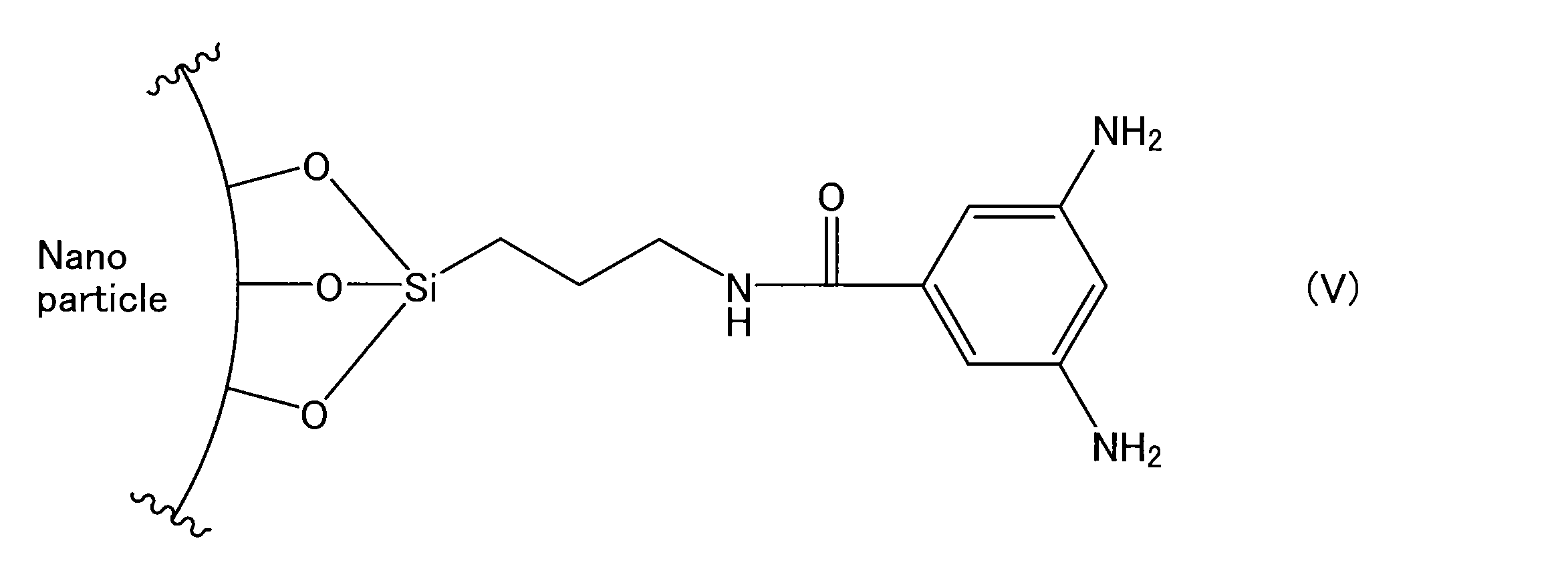
多孔性支持体3は、中間層2を介して分離機能層1を支持する。多孔性支持体3としては、例えば、不織布;多孔質ポリテトラフルオロエチレン;芳香族ポリアミド繊維;多孔質金属;焼結金属;多孔質セラミック;多孔質ポリエステル;多孔質ナイロン;活性化炭素繊維;ラテックス;シリコーン;シリコーンゴム;ポリフッ化ビニル、ポリフッ化ビニリデン、ポリウレタン、ポリプロピレン、ポリエチレン、ポリスチレン、ポリカーボネート、ポリスルホン、ポリエーテルエーテルケトン、ポリアクリロニトリル、ポリイミド及びポリフェニレンオキシドからなる群より選ばれる少なくとも1つを含む透過性(多孔質)ポリマー;連続気泡又は独立気泡を有する金属発泡体;連続気泡又は独立気泡を有するポリマー発泡体;シリカ;多孔質ガラス;メッシュスクリーンなどが挙げられる。多孔性支持体3は、これらのうちの2種以上を組み合わせたものであってもよい。
分離膜10は、例えば、次の方法によって作製することができる。まず、多孔性支持体3及び中間層2の積層体を準備する。この積層体は、例えば、次の方法によって作製できる。まず、中間層2の材料を含む塗布液を調製する。次に、多孔性支持体3の上に、中間層2の材料を含む塗布液を塗布し、塗布膜を形成する。塗布液の塗布方法は、特に限定されず、例えば、スピンコート法、ディップコート法などを利用できる。ワイヤーバーなどを利用して塗布液を塗布してもよい。次に、塗布膜を乾燥し、中間層2を形成する。塗布膜の乾燥は、例えば、加熱条件下で行うことができる。塗布膜の加熱温度は、例えば50℃以上である。塗布膜の加熱時間は、例えば1分以上であり、5分以上であってもよい。さらに、中間層2の表面には、必要に応じて易接着処理を施してもよい。易接着処理としては、下塗り剤の塗布、コロナ放電処理、プラズマ処理などの表面処理が挙げられる。
本実施形態において、分離膜10は、典型的には平膜である。ただし、分離膜10は、平膜以外の形状であってもよく、例えば、中空糸膜であってもよい。一例として、中空糸膜としての分離膜10は、分離機能層1及び多孔性支持体3を備えている一方、中間層2を備えていなくてもよい。
本実施形態の分離膜10は、分離機能層1に起因して、混合気体に含まれる酸性ガスを優先的に透過させることができる。一例として、分離膜10を透過する二酸化炭素の透過速度T2は、例えば50GPU以上であり、80GPU以上、100GPU以上、120GPU以上、150GPU以上、さらには180GPU以上であってもよい。透過速度T2の上限は、特に限定されず、例えば1000GPU以下である。
図3に示すとおり、本実施形態の膜分離装置100は、分離膜10及びタンク20を備えている。膜分離装置100では、分離膜10に代えて、分離機能層1を単体で使用することも可能である。タンク20は、第1室21及び第2室22を備えている。分離膜10は、タンク20の内部に配置されている。タンク20の内部において、分離膜10は、第1室21と第2室22とを隔てている。分離膜10は、タンク20の1対の壁面の一方から他方まで延びている。
膜分離装置100は、スパイラル型の膜エレメント、中空糸膜エレメントなどであってもよい。図4は、スパイラル型の膜エレメントを示している。図4の膜分離装置110は、中心管41及び積層体42を備えている。積層体42が分離膜10を含んでいる。積層体42は、分離膜10に代えて、分離機能層1を単体で含んでいてもよい。
まず、ポリマーAとしてのポリビニルアルコール(PVA、Sigma Aldrich社製、重量平均分子量85000-124000、けん化度87-89mol%)4gを水36gに添加して、90℃まで昇温した。PVAが完全に溶解するまで撹拌し、PVA水溶液を調製した。次に、ポリマーBとしてのポリビニルピロリドン(PVP、Sigma Aldrich社製、重量平均分子量360000)1.6gを水38.4gに添加した。25℃でPVPが完全に溶解するまで撹拌し、PVP水溶液を調製した。
イオン液体Lと、ポリマーA及びBとの重量比を表1に示すように変更したことを除き、例A1と同じ方法によって、例A2~A3の分離機能層(自立膜)を得た。
ポリマーBを用いなかったこと、及び、ポリマーAに対するイオン液体Lの重量比を75/25としたことを除き、例A1と同じ方法によって、例A4の分離機能層(自立膜)を得た。
ポリマーAを用いなかったこと、及び、ポリマーBに対するイオン液体Lの重量比を75/25としたことを除き、例A1と同じ方法によって、分離機能層(自立膜)の作製を試みたが、混合液が十分に固まらず、分離機能層は得られなかった。
例A1~A4の分離機能層について、上述した方法によって圧縮試験を行った。このとき、分離機能層に含まれるイオン液体Lの重量に対する、分離機能層に対して圧縮試験を行ったときに分離機能層から漏洩したイオン液体の重量の比率(漏洩率)を特定した。結果を表1に示す。
例A1~A4の分離機能層について、上述した方法によって引張試験を行い、破断強度を測定した。結果を表1に示す。
例A1~A4の分離機能層について、差圧法ガス透過試験装置(GTRテック社製、GTR-31AHND)を用いて、以下の方法により、二酸化炭素の透過速度T1、二酸化炭素の透過係数C1、及び、水素に対する二酸化炭素の分離係数α1(CO2/H2)を測定した。まず、約3cm四方に切断した分離機能層を金属セル中にセットし、リークが発生しないようにOリングでシールした。次に、分離機能層の一方の主面に混合気体が接触するように、金属セル内に混合気体を注入した。混合気体は、実質的に二酸化炭素及び水素からなっていた。混合気体における二酸化炭素の濃度は、標準状態で50vol%であった。金属セル内に注入された混合気体は、温度が30℃であり、圧力が0.1MPaであった。次に、分離機能層の他方の主面に隣接する金属セル内の空間を真空ポンプで減圧した。このとき、この空間は、空間内の圧力が測定環境における大気圧に対して0.1MPa小さくなるように減圧されていた。これにより、分離機能層の他方の主面から透過流体が得られた。得られた透過流体の組成、透過流体の重量などに基づいて、透過速度T1、透過係数C1及び分離係数α1を算出した。結果を表1に示す。

まず、多孔性支持体としての限外ろ過膜(日東電工社製、NTU-3175M)を準備した。次に、シリコーン樹脂(モメンティブパフォーマンスマテリアルズ社製、YSR3022)の6wt%デカン溶液を調製し、さらに、触媒(モメンティブパフォーマンスマテリアルズ社製、YC6831)をシリコーン樹脂固形分の1%、硬化遅延剤としてアセチルアセトン(富士フイルム和光純薬株式会社製)をシリコーン樹脂固形分の3%添加した。得られた溶液を多孔性支持体の上に塗布した。塗布は、バーコーターを用いて塗工厚さ68.6μmの条件で行った。次に、得られた塗布膜を130℃で5分乾燥させた。これにより、多孔性支持体及び中間層の積層体を得た。中間層の厚さは約1μmであった。さらに、積層体について、出力0.1kWでコロナ処理を施した。
イオン液体Lや、ポリマーA及びBの重量比を表2に示すように変更したことを除き、例B1と同じ方法によって、例B2~B5の分離膜(複合膜)を得た。
イオン液体Lとして1-エチル-3-メチルイミダゾリウムトリシアノメタニド([EMIM][TCM])を用いたことを除き、例B1と同じ方法によって、例B6の分離膜(複合膜)を得た。
ポリマーBを用いなかったこと、及び、ポリマーAに対するイオン液体Lの重量比を75/25としたことを除き、例B1と同じ方法によって、例B7の分離膜(複合膜)を得た。
まず、三ツ口フラスコに還流管を取り付け、合成装置を組み立てた。三方コックには、真空ポンプ及びN2ボンベをつないだ。真空引きを行うとともに、2分間に1回窒素を供給する動作を1セットとして、合計5セットの窒素置換を行った。窒素置換後、ガラスシリンジを用いて、1,4-ジオキサンを三ツ口フラスコ内に加えた。次に、バイアル瓶に、N,N-ジメチルアクリルアミド(DMAAm)(14.6g、147.28mmol)、N-アクリロイルオキシスクシンイミド(NSA)(1.32g、7.80mmol)及び2,2’-アゾビスイソブチロニトリル(AIBN)(0.256g、1.56mmol)をこの順に量り取り、数分攪拌した。DMAAmとNSAのモル比(DMAAm/NSA)は、95/5であった。シリンジを用いて、得られた混合物を三ツ口フラスコ内に加えた。三ツ口フラスコ内の溶液をスターラーで10分程攪拌した。次に、還流管を冷却装置に接続し、60℃に設定した油浴槽を用いて還流下で24時間重合を行った。
ポリマーAを用いなかったこと、及び、ポリマーBに対するイオン液体Lの重量比を75/25としたことを除き、例B1と同じ方法によって、分離膜(複合膜)の作製を試みたが、混合液が十分に固まらず、分離機能層が形成されなかった。
例A1~A4について上述した方法によって、例B1~B8の分離膜について、二酸化炭素の透過速度T2、及び、水素に対する二酸化炭素の分離係数α2(CO2/H2)を測定した。結果を表2に示す。
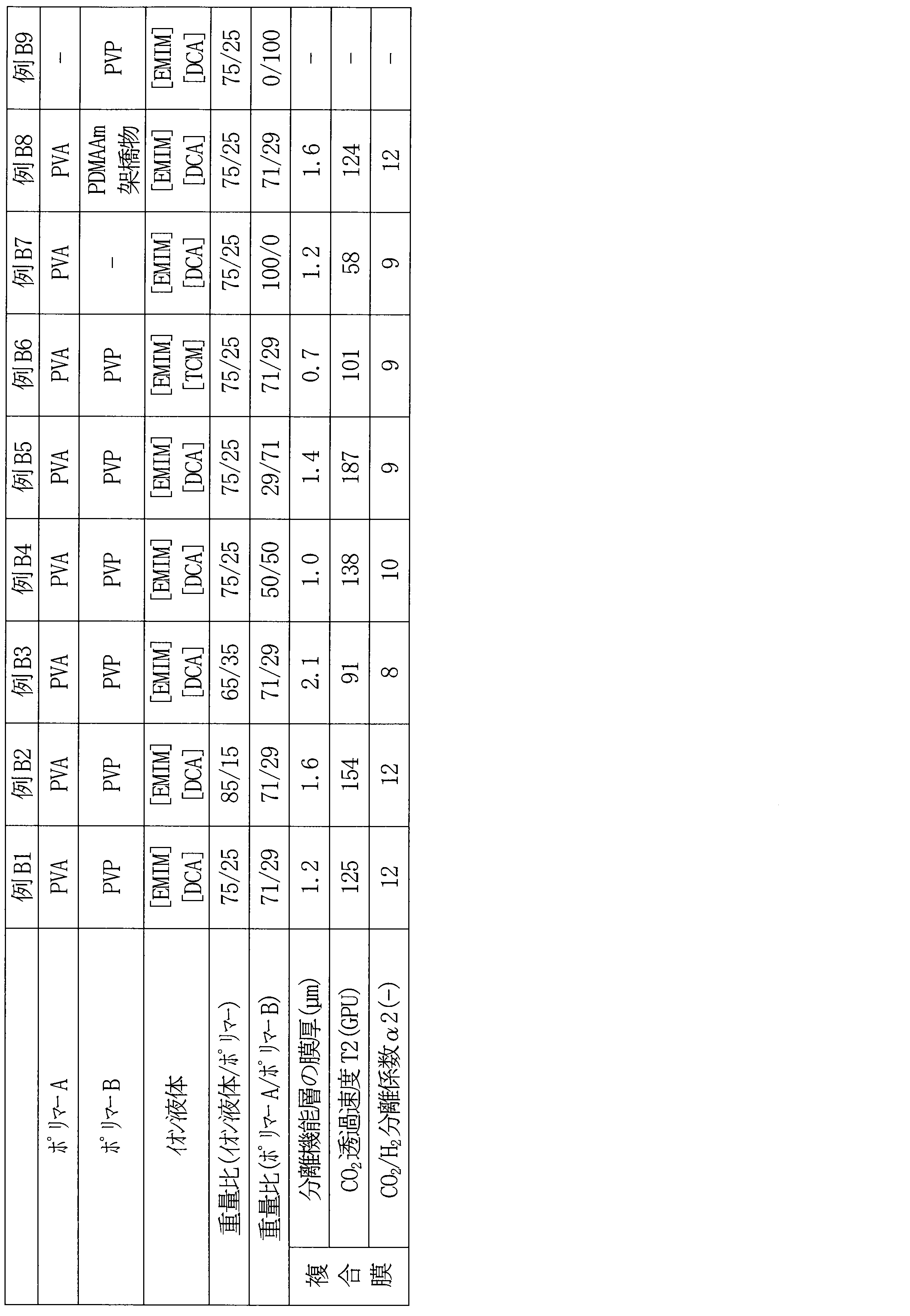
ポリマーAとして、ポリビニルアルコールa1(PVA、東京化成工業製、重合度2000、重量平均分子量88000、けん化度80mol%)を用いたこと、及び、ポリマーAに対するイオン液体Lの重量比を40/60としたことを除き、例A4と同じ方法によって、例C1の分離機能層(自立膜)を得た。
ポリマーAとして、ポリビニルアルコールa2(PVA、Sigma Aldrich社製、重量平均分子量85000-124000、けん化度87-89mol%)を用いたことを除き、例C1と同じ方法によって、例C2の分離機能層(自立膜)を得た。
ポリマーAとして、ポリビニルアルコールa3(PVA、Sigma Aldrich社製、重量平均分子量85000-124000、けん化度99mol%)を用いたことを除き、例C1と同じ方法によって、例C3の分離機能層(自立膜)を得た。
ポリマーAの種類、及び、ポリマーAに対するイオン液体Lの重量比を表3に示すように変更したことを除き、例C1と同じ方法によって、例C4~C12の分離機能層(自立膜)を得た。
例C1~C12の分離機能層について、上述した方法によって圧縮試験を行った。このとき、分離機能層に含まれるイオン液体Lの重量に対する、分離機能層に対して圧縮試験を行ったときに分離機能層から漏洩したイオン液体の重量の比率(漏洩率)を特定した。結果を表3に示す。
例C1~C12の分離機能層について、上述した方法によって引張試験を行い、破断エネルギー及び破断強度(破断応力)を測定した。結果を表3に示す。
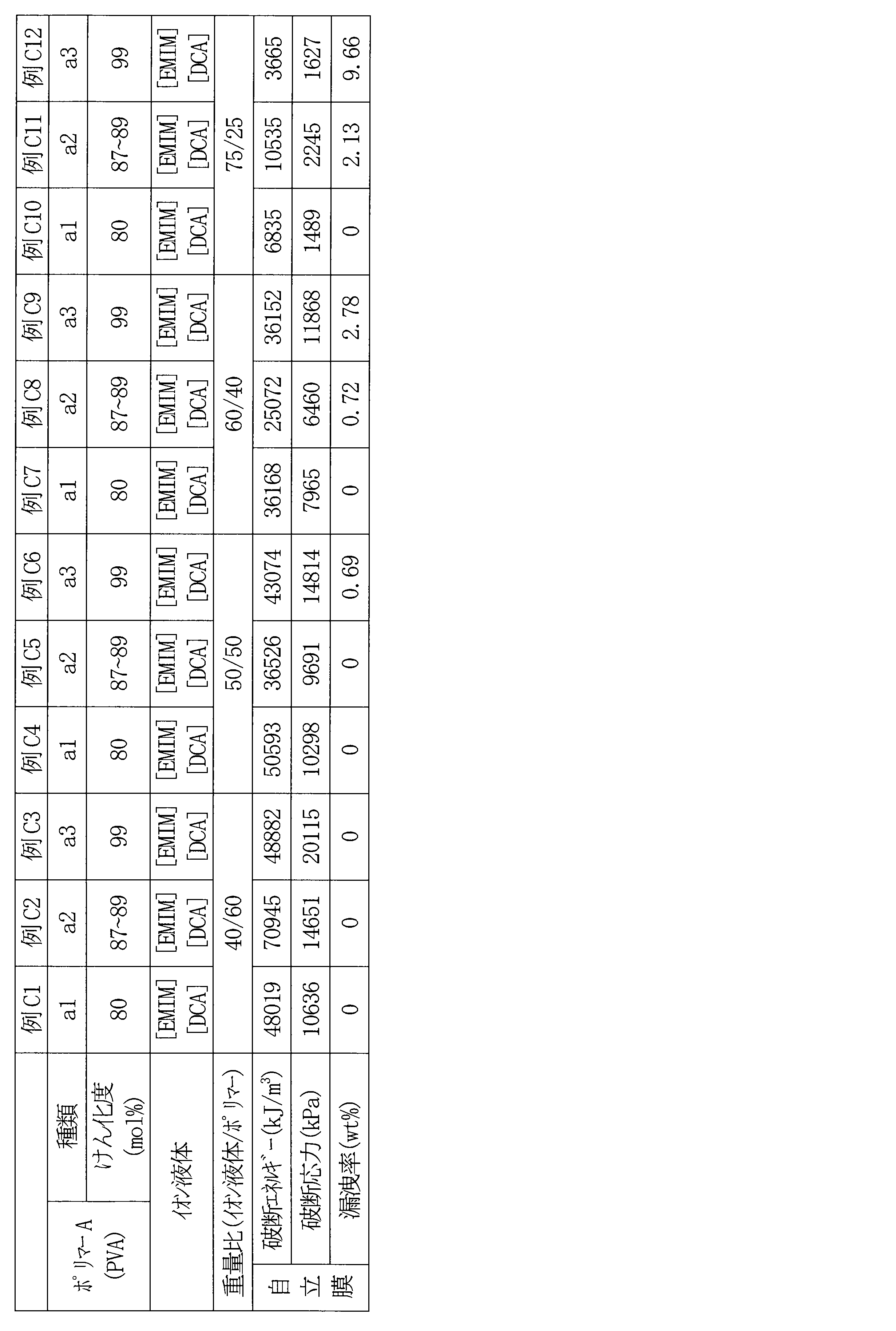
Claims (16)
- イオン液体と、
前記イオン液体中で結晶構造を形成する親水性のポリマーAと、
前記ポリマーAとは異なるポリマーBと、
を含む、分離機能層。 - 前記イオン液体が親水性又は両親媒性を有する、請求項1に記載の分離機能層。
- 前記イオン液体は、1-エチル-3-メチルイミダゾリウムジシアンアミド、及び1-エチル-3-メチルイミダゾリウムトリシアノメタニドからなる群より選ばれる少なくとも1つを含む、請求項1に記載の分離機能層。
- 前記ポリマーAがヒドロキシル基を有する、請求項1に記載の分離機能層。
- 前記ポリマーAは、前記ヒドロキシル基に由来する水素結合を介して、前記ポリマーBと結合している、請求項4に記載の分離機能層。
- 前記ポリマーAがポリビニルアルコールを含む、請求項1に記載の分離機能層。
- 前記ポリマーBは、アミド基及びイミド基からなる群より選ばれる少なくとも1つを有する、請求項1に記載の分離機能層。
- 前記ポリマーBが直鎖状である、請求項1に記載の分離機能層。
- 前記ポリマーBがポリビニルピロリドンを含む、請求項1に記載の分離機能層。
- 前記イオン液体の含有率が60wt%以上である、請求項1に記載の分離機能層。
- 厚さが100μm以下である、請求項1に記載の分離機能層。
- 破断強度が100kPa以上である、請求項1に記載の分離機能層。
- 前記分離機能層の一方の面に隣接する空間に、二酸化炭素及び水素からなる混合気体を供給するとともに、前記分離機能層の他方の面に隣接する空間を減圧した場合に、前記分離機能層を透過する二酸化炭素の透過係数が100Barrer以上である、請求項1に記載の分離機能層。
ここで、前記混合気体における前記二酸化炭素の濃度は、標準状態で50vol%であり、前記一方の面に隣接する空間に供給される前記混合気体は、温度が30℃であり、圧力が0.1MPaであり、前記他方の面に隣接する空間は、当該空間内の圧力が測定環境における大気圧に対して0.1MPa小さくなるように減圧されている。 - 酸性ガスを含む混合気体から前記酸性ガスを分離するために用いられる、請求項1に記載の分離機能層。
- 請求項1~14のいずれか1項に記載の分離機能層と、
前記分離機能層を支持している多孔性支持体と、
を備えた、分離膜。 - 分離機能層と、
前記分離機能層を支持している多孔性支持体と、
を備え、
前記分離機能層は、イオン液体と、前記イオン液体中で結晶構造を形成する親水性のポリマーAとを含む、分離膜。
Priority Applications (2)
| Application Number | Priority Date | Filing Date | Title |
|---|---|---|---|
| JP2024576183A JPWO2024166604A1 (ja) | 2023-02-10 | 2024-01-12 | |
| CN202480006667.4A CN120456975A (zh) | 2023-02-10 | 2024-01-12 | 分离功能层及分离膜 |
Applications Claiming Priority (2)
| Application Number | Priority Date | Filing Date | Title |
|---|---|---|---|
| JP2023-018949 | 2023-02-10 | ||
| JP2023018949 | 2023-02-10 |
Publications (1)
| Publication Number | Publication Date |
|---|---|
| WO2024166604A1 true WO2024166604A1 (ja) | 2024-08-15 |
Family
ID=92262312
Family Applications (1)
| Application Number | Title | Priority Date | Filing Date |
|---|---|---|---|
| PCT/JP2024/000643 Ceased WO2024166604A1 (ja) | 2023-02-10 | 2024-01-12 | 分離機能層及び分離膜 |
Country Status (4)
| Country | Link |
|---|---|
| JP (1) | JPWO2024166604A1 (ja) |
| CN (1) | CN120456975A (ja) |
| TW (1) | TW202440216A (ja) |
| WO (1) | WO2024166604A1 (ja) |
Cited By (1)
| Publication number | Priority date | Publication date | Assignee | Title |
|---|---|---|---|---|
| CN119633622A (zh) * | 2025-01-21 | 2025-03-18 | 江西浦合盛业环保科技有限公司 | 一种用于回收废水中贵金属的功能膜及其制备方法 |
Citations (5)
| Publication number | Priority date | Publication date | Assignee | Title |
|---|---|---|---|---|
| JP2010222228A (ja) | 2009-03-25 | 2010-10-07 | Tokyo Metropolitan Univ | 表面ハイパーブランチまたはデンドリマー修飾無機ナノ粒子および気体分離膜 |
| WO2017163786A1 (ja) * | 2016-03-24 | 2017-09-28 | 次世代型膜モジュール技術研究組合 | ガス分離膜 |
| WO2019130470A1 (ja) * | 2017-12-27 | 2019-07-04 | 株式会社ルネッサンス・エナジー・リサーチ | Co2除去方法及び装置 |
| JP2020037688A (ja) | 2018-08-29 | 2020-03-12 | 日東電工株式会社 | イオン性液体含有構造体の製造方法及びイオン性液体含有構造体 |
| WO2022059368A1 (ja) * | 2020-09-17 | 2022-03-24 | 日東電工株式会社 | 分離膜、分離膜の製造方法及び分離膜を製造するための塗布液 |
-
2024
- 2024-01-12 WO PCT/JP2024/000643 patent/WO2024166604A1/ja not_active Ceased
- 2024-01-12 CN CN202480006667.4A patent/CN120456975A/zh active Pending
- 2024-01-12 JP JP2024576183A patent/JPWO2024166604A1/ja active Pending
- 2024-01-31 TW TW113103778A patent/TW202440216A/zh unknown
Patent Citations (5)
| Publication number | Priority date | Publication date | Assignee | Title |
|---|---|---|---|---|
| JP2010222228A (ja) | 2009-03-25 | 2010-10-07 | Tokyo Metropolitan Univ | 表面ハイパーブランチまたはデンドリマー修飾無機ナノ粒子および気体分離膜 |
| WO2017163786A1 (ja) * | 2016-03-24 | 2017-09-28 | 次世代型膜モジュール技術研究組合 | ガス分離膜 |
| WO2019130470A1 (ja) * | 2017-12-27 | 2019-07-04 | 株式会社ルネッサンス・エナジー・リサーチ | Co2除去方法及び装置 |
| JP2020037688A (ja) | 2018-08-29 | 2020-03-12 | 日東電工株式会社 | イオン性液体含有構造体の製造方法及びイオン性液体含有構造体 |
| WO2022059368A1 (ja) * | 2020-09-17 | 2022-03-24 | 日東電工株式会社 | 分離膜、分離膜の製造方法及び分離膜を製造するための塗布液 |
Non-Patent Citations (1)
| Title |
|---|
| "Users Handbook", 2007, CRC PRESS, article "Hansen Solubility Parameters" |
Cited By (2)
| Publication number | Priority date | Publication date | Assignee | Title |
|---|---|---|---|---|
| CN119633622A (zh) * | 2025-01-21 | 2025-03-18 | 江西浦合盛业环保科技有限公司 | 一种用于回收废水中贵金属的功能膜及其制备方法 |
| CN119633622B (zh) * | 2025-01-21 | 2025-06-20 | 江西浦合盛业环保科技有限公司 | 一种用于回收废水中贵金属的功能膜及其制备方法 |
Also Published As
| Publication number | Publication date |
|---|---|
| TW202440216A (zh) | 2024-10-16 |
| CN120456975A (zh) | 2025-08-08 |
| JPWO2024166604A1 (ja) | 2024-08-15 |
Similar Documents
| Publication | Publication Date | Title |
|---|---|---|
| JP7328083B2 (ja) | イオン性液体含有構造体の製造方法 | |
| EP1769841B1 (en) | Hydrophilic membrane and associated method | |
| CN111094361B (zh) | 含有离子性液体的结构体的制造方法及含有离子性液体的结构体 | |
| US8992668B2 (en) | Gas separation membrane and method for producing the same, and method for separating gas mixture, gas separation membrane module and gas separation apparatus using the same | |
| KR101951509B1 (ko) | 이온 교환 조성물, 제조 방법 및 이로부터 제조된 물질 | |
| US20110127219A1 (en) | Porous membranes made up of organopolysiloxane copolymers | |
| JP6103708B2 (ja) | イオン性液体含有相互侵入網目構造体およびその製造方法 | |
| CN104607074B (zh) | 一种含偶氮苯聚酰胺反渗透复合膜的制备方法 | |
| JP2021165399A (ja) | ポリ(アミド−イミド)フィルムの製造方法及びそれにより製造されたポリ(アミド−イミド)フィルム | |
| US20240416291A1 (en) | Separation membrane and method for manufacturing same | |
| TW201945068A (zh) | 石墨烯氧化物薄膜保護性塗料 | |
| US20230347284A1 (en) | Separation membrane, separation membrane manufacturing method, and coating liquid for manufacturing separation membrane | |
| EP4400204A1 (en) | Separation function layer, separation membrane, and production method for separation function layer | |
| TW202440216A (zh) | 分離機能層及分離膜 | |
| WO2023119879A1 (ja) | 分離機能層、分離膜及び膜分離方法 | |
| WO2022185891A1 (ja) | 分離膜 | |
| JP2025152873A (ja) | 分離機能層、及び分離膜 | |
| JP2020204020A (ja) | 樹脂組成物、硬化膜および電子部品 | |
| US7291696B2 (en) | Composition and associated method | |
| WO2026034205A1 (ja) | 分離膜及びその製造方法 | |
| CN120641512A (zh) | 嵌段共聚物、组合物及使用它们的物品 | |
| JP2025137156A (ja) | 分離機能層、分離膜、及び分離機能層の製造方法 | |
| KR20250156256A (ko) | 고분자막, 이를 포함하는 기체분리막 및 이의 제조 방법 | |
| CN108839416A (zh) | 一种高表面能自粘膜及其制备方法 | |
| KR101056452B1 (ko) | 나프탈렌계 유방성 크로모닉 액정 조성물 및 이를 이용하여 제조된 다층구조 편광필름 |
Legal Events
| Date | Code | Title | Description |
|---|---|---|---|
| 121 | Ep: the epo has been informed by wipo that ep was designated in this application |
Ref document number: 24753051 Country of ref document: EP Kind code of ref document: A1 |
|
| WWE | Wipo information: entry into national phase |
Ref document number: 202480006667.4 Country of ref document: CN |
|
| ENP | Entry into the national phase |
Ref document number: 2024576183 Country of ref document: JP Kind code of ref document: A |
|
| WWE | Wipo information: entry into national phase |
Ref document number: 2024576183 Country of ref document: JP |
|
| WWP | Wipo information: published in national office |
Ref document number: 202480006667.4 Country of ref document: CN |
|
| NENP | Non-entry into the national phase |
Ref country code: DE |
|
| WWW | Wipo information: withdrawn in national office |
Ref document number: 2024753051 Country of ref document: EP |
|
| WWP | Wipo information: published in national office |
Ref document number: 2024753051 Country of ref document: EP |