WO2024166570A1 - 情報処理装置、プログラム、情報処理方法 - Google Patents
情報処理装置、プログラム、情報処理方法 Download PDFInfo
- Publication number
- WO2024166570A1 WO2024166570A1 PCT/JP2023/046379 JP2023046379W WO2024166570A1 WO 2024166570 A1 WO2024166570 A1 WO 2024166570A1 JP 2023046379 W JP2023046379 W JP 2023046379W WO 2024166570 A1 WO2024166570 A1 WO 2024166570A1
- Authority
- WO
- WIPO (PCT)
- Prior art keywords
- page
- information processing
- diagram
- transition
- processing device
- Prior art date
- Legal status (The legal status is an assumption and is not a legal conclusion. Google has not performed a legal analysis and makes no representation as to the accuracy of the status listed.)
- Ceased
Links
Images






Classifications
-
- G—PHYSICS
- G06—COMPUTING OR CALCULATING; COUNTING
- G06F—ELECTRIC DIGITAL DATA PROCESSING
- G06F3/00—Input arrangements for transferring data to be processed into a form capable of being handled by the computer; Output arrangements for transferring data from processing unit to output unit, e.g. interface arrangements
- G06F3/01—Input arrangements or combined input and output arrangements for interaction between user and computer
- G06F3/048—Interaction techniques based on graphical user interfaces [GUI]
- G06F3/0481—Interaction techniques based on graphical user interfaces [GUI] based on specific properties of the displayed interaction object or a metaphor-based environment, e.g. interaction with desktop elements like windows or icons, or assisted by a cursor's changing behaviour or appearance
- G06F3/0483—Interaction with page-structured environments, e.g. book metaphor
-
- G—PHYSICS
- G06—COMPUTING OR CALCULATING; COUNTING
- G06F—ELECTRIC DIGITAL DATA PROCESSING
- G06F3/00—Input arrangements for transferring data to be processed into a form capable of being handled by the computer; Output arrangements for transferring data from processing unit to output unit, e.g. interface arrangements
- G06F3/01—Input arrangements or combined input and output arrangements for interaction between user and computer
- G06F3/048—Interaction techniques based on graphical user interfaces [GUI]
- G06F3/0487—Interaction techniques based on graphical user interfaces [GUI] using specific features provided by the input device, e.g. functions controlled by the rotation of a mouse with dual sensing arrangements, or of the nature of the input device, e.g. tap gestures based on pressure sensed by a digitiser
- G06F3/0488—Interaction techniques based on graphical user interfaces [GUI] using specific features provided by the input device, e.g. functions controlled by the rotation of a mouse with dual sensing arrangements, or of the nature of the input device, e.g. tap gestures based on pressure sensed by a digitiser using a touch-screen or digitiser, e.g. input of commands through traced gestures
-
- G—PHYSICS
- G06—COMPUTING OR CALCULATING; COUNTING
- G06F—ELECTRIC DIGITAL DATA PROCESSING
- G06F3/00—Input arrangements for transferring data to be processed into a form capable of being handled by the computer; Output arrangements for transferring data from processing unit to output unit, e.g. interface arrangements
- G06F3/14—Digital output to display device ; Cooperation and interconnection of the display device with other functional units
Definitions
- This technology relates to an information processing device, program, and information processing method that switches the display of multiple pages.
- the aim of this technology is to reduce unnecessary operations for users.
- An information processing device includes a display control unit that causes a diagram for a second page to be displayed on a display unit before a transition to a second page different from the first page is completed in response to a transition operation from a first page to the second page different from the first page. This allows information about the second page to be presented to the user before the screen transition to the second page.
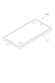
- FIG. 1 is a diagram showing an external appearance of a smartphone which is one aspect of an information processing device according to an embodiment of the present technology
- FIG. 2 is a block diagram showing an example of a hardware configuration of an information processing device.
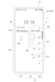
- FIG. 2 is a diagram showing an example of a home screen displayed on a display unit of the smartphone.
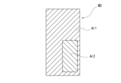
- FIG. 13 is a diagram showing a state in which a plurality of applications are displayed on a display unit in an overlapping display mode.
- FIG. 13 is a diagram showing a state in which a plurality of applications are displayed on a display unit in a split display mode.
- FIG. 13 is a diagram showing a state in which a setting screen is displayed on the display unit, and shows a state in which a first page for setting the superimposed display mode is displayed.
- FIG. 2 is a diagram showing a state in which a setting screen is displayed on a display unit, in which a first page for setting a split display mode is displayed.
- FIG. FIG. 13 is a diagram showing a state during transition from a first page to a second page. 9 is a diagram showing a state in the middle of transition from the first page to the second page, in which the first page has been moved further to the left than in FIG. 8 .
- FIG. FIG. 13 is a diagram showing a state during transition from the second page to the first page.
- 11 is a diagram showing a state in the middle of transition from the second page to the first page, in which the second page has been moved further to the right than in FIG. 10 .
- FIG. 13 is a diagram for explaining animation of a transition diagram for a second page.
- FIG. 13 is a diagram illustrating animation of a transition diagram for a first page.
- 13 is a flowchart of a display control process.
- 13 is a flowchart illustrating an animation process.
- 13 is a flowchart showing another example of animation processing.
- Configuration of information processing device A configuration example of an information processing device 1 according to the present technology will be described.
- a smartphone 1A serving as a mobile terminal device is taken as an example of the information processing device 1, the implementation of the present technology is not limited thereto.
- the information processing device 1 may be a mobile terminal device such as a tablet terminal other than the smartphone 1A.
- the smartphone 1A is configured to include a control unit and a display unit, the present technology can also be applied to an information processing device 1 such as a personal computer that includes only a control unit and an external display unit.
- the present technology can also be applied to a stationary information processing device 1 as well as a portable information processing device 1.
- the smartphone 1A as the information processing device 1 is merely one embodiment of the present technology.
- FIG. 1 shows the appearance of a smartphone 1A as an information processing device 1.
- the smartphone 1A is configured to include a housing section 2 formed in a box shape with an internal space formed therein and various parts arranged inside and outside, a display section 3 attached so as to be fitted into an opening formed in the housing section 2, and various operating buttons (not shown).
- the housing unit 2 and the display unit 3 are provided with sensors that detect user operations.
- the sensor provided in the display unit 3 detects that the user has performed a touch operation or a swipe operation on the display unit 3.
- the display unit 3 functions as a so-called touch panel.
- the smartphone 1A is provided with a sensor in the housing 2 or the display 3 that detects user operations near both the left and right ends of the display 3.
- This sensor may be replaced by a sensor that realizes a touch panel function.
- This sensor may also be a sensor that detects only user operations at one end of both the left and right ends.
- the hardware configuration of an information processing device 1 such as a smartphone 1A will be described with reference to Fig. 2.
- the CPU 71 of the information processing device 1 executes various processes according to programs stored in a ROM 72 or a non-volatile memory unit 74 such as an EEPROM (Electrically Erasable Programmable Read-Only Memory), or programs loaded from a storage unit 79 to a RAM 73.
- the RAM 73 also stores data necessary for the CPU 71 to execute various processes, as appropriate.
- the CPU 71, the ROM 72, the RAM 73, and the non-volatile memory unit 74 are interconnected via a bus 83. To this bus 83, an input/output interface 75 is also connected.
- the input/output interface 75 is connected to an input unit 76 including an operator and an operating device.
- the input unit 76 may be various types of operators or operation devices such as a keyboard, a mouse, keys, a dial, the above-mentioned touch panel, a touch pad, a remote controller, or the like.
- An operation by the user is detected by the input unit 76 , and a signal corresponding to the input operation is interpreted by the CPU 71 .
- a display unit 77 (including the display unit 3 of the smartphone 1A described above) consisting of an LCD or an organic EL panel, and an audio output unit 78 consisting of a speaker, etc. are connected to the input/output interface 75 either integrally or separately.
- the display unit 77 is a display unit that performs various displays, and is configured, for example, by a display device provided in the housing of the computer device, or a separate display device connected to the computer device.
- the display unit 77 executes display of images for various image processing, moving images to be processed, etc. on the display screen based on instructions from the CPU 71.
- the display unit 77 also displays various operation menus, icons, messages, etc., i.e., GUI (Graphical User Interface), based on instructions from the CPU 71. That is, the CPU 71 functions as a display control unit that causes the display unit 77 to display a predetermined image.
- GUI Graphic User Interface
- the input/output interface 75 may also be connected to a storage unit 79 such as a hard disk or solid-state memory, or a communication unit 80 such as a modem.
- a storage unit 79 such as a hard disk or solid-state memory
- a communication unit 80 such as a modem.
- the communication unit 80 performs communication processing via a transmission path such as the Internet, and communication with various devices via wired/wireless communication, bus communication, etc.
- a drive 81 is also connected to the input/output interface 75 as required, and a removable storage medium 82 such as a magnetic disk, an optical disk, a magneto-optical disk, or a semiconductor memory is appropriately mounted thereon.
- the drive 81 allows data files such as image files and various computer programs to be read from the removable storage medium 82.
- the read data files are stored in the storage unit 79, and images and sounds contained in the data files are output on the display unit 77 and the sound output unit 78.
- the computer programs and the like read from the removable storage medium 82 are installed in the storage unit 79 as necessary.
- software for the processing of this embodiment can be installed via network communication by the communication unit 80 or via the removable storage medium 82.
- the software may be stored in advance in the ROM 72, the storage unit 79, etc.
- the CPU 71 performs processing operations based on various programs to realize screen displays, which will be described later, on the smartphone 1A.
- the information processing device 1 is not limited to being configured by a single computer device as shown in Fig. 2, but may be configured by a system of multiple computer devices.
- the multiple computer devices may be systemized using a LAN or the like, or may be located in a remote location using a VPN or the like using the Internet or the like.
- the multiple computer devices may include computer devices serving as a server group (cloud) available through a cloud computing service.
- Each screen has items such as text, icons, images, etc. appropriately arranged based on a page selected by the user from a plurality of pages.
- the "page” referred to here may be a so-called pane, which is a predetermined display unit virtually arranged adjacently in the vertical or horizontal direction and allows the display to be switched for each adjacent display unit, or it may be a display unit that can be switched by tabs.
- FIG. 3 shows an example of a home screen 100, which is one of the screens displayed on the display unit 3 of the smartphone 1A.
- the home screen 100 includes a date and time display section 100a that displays date and time information, an icon display section 100b that displays various icons PF, and a search section 100c that allows the input of a search query.
- the display mode of the home screen 100 shown in FIG. 3 is one in which one page is displayed across substantially the entirety of the display unit 3. This display mode is referred to as the "full-screen display mode M1.”
- the CPU 71 causes an image of the application AP to be displayed on the display unit 3 in the full-screen display mode M1.
- displaying an image of the application AP on the display unit 3 may be simply referred to as "displaying the application AP”.
- the smartphone 1A is capable of simultaneously displaying multiple applications AP on the display unit 3.
- the first application AP1 is displayed across substantially the entire display unit 3, and a superimposed area is provided in a portion of that area.
- the second application AP2 is then displayed in the superimposed area.
- This display mode is referred to as the "superimposed display mode M2.”
- the display unit 3 in the overlapping display mode M2 includes an area other than the overlapping area and the overlapping area.
- the area other than the overlapping area where the first application AP1 is displayed is referred to as a "first area Ar1," and the overlapping area where the second application AP2 is displayed is referred to as a "second area Ar2.”
- FIG. 4 shows an example of the overlapping display mode M2, in which a first application AP1 is displayed in a first area Ar1, and a second application AP2 is displayed in a second area Ar2.
- an operation for moving the second area Ar2 is possible, and by performing this operation, the position of the second area Ar2 relative to the first area Ar1 can be changed.
- the second display mode for simultaneously displaying multiple applications AP is to divide the display unit 3 into two areas aligned vertically or horizontally, with one area being the first area Ar1 in which the first application AP1 is displayed, and the other area being the second area Ar2 in which the second application AP2 is displayed.
- This display mode is referred to as the "split display mode M3.”
- FIG. 5 shows an example of a split display mode M3, in which a first area Ar1 and a second area Ar2 are split vertically.
- the split display mode M3 for example, it is possible to move the boundary between the two areas, and by performing this operation, the area ratio between the first area Ar1 and the second area Ar2 can be changed.
- the CPU 71 of the smartphone 1A is capable of controlling the display of a setting screen 101 that allows switching between full screen display mode M1, overlapping display mode M2, and split display mode M3, and allows these settings to be made.
- the setting screen 101 is a screen that displays a screen for changing the layout mode of the launched application AP.
- the display of the settings screen 101 may be performed by any user operation, but as an example, we will explain the use of a function called Side Sense (registered trademark).
- Side sense is a function that displays a predetermined menu screen or the like in response to a user's operation on the edge of the display unit 3.
- the operation target area SA for the side sense function is located approximately in the center in the vertical direction on the right edge of the display unit 3.
- the setting screen 101 is displayed by the side sense function shown in FIG. 6.
- the settings screen 101 consists of a tab area 101a and a main area 101b.
- the tab area 101a is configured to include two tabs TB, each of which corresponds to the settings for the overlapped display mode M2 and the split display mode M3. That is, of the two tabs TB in the settings screen 101, the tab TB1 on the left corresponds to the setting page for the overlapped display mode M2, and the tab TB2 on the right corresponds to the setting page for the split display mode M3.
- FIG. 6 shows the state in which the tab TB1 on the left side is selected.
- a horizontally long bar-shaped indicator In is arranged to indicate the selected tab TB.
- the main area 101b displays content according to the selected tab TB1.
- a screen for selecting a first application AP1 to be displayed in the first area Ar1 in the overlapping display mode M2 and a second application AP2 to be displayed in the second area Ar2 is displayed in the main area 101b.
- a screen for selecting a first application AP1 to be displayed in the first area Ar1 in split display mode M3 and a second application AP2 to be displayed in the second area Ar2 is displayed in the main area 101b (see FIG. 7).
- first settings screen 101A the screen shown in FIG. 6 on which the page corresponding to the selected tab TB1 of the settings screen 101 is displayed
- first page P1 the page displayed in the main area 101b of the first settings screen 101A
- the screen shown in FIG. 7 on which the page corresponding to the selected tab TB2 of the setting screen 101 is displayed is referred to as the "second setting screen 101B," and the page displayed in the main area 101b of the second setting screen 101B is referred to as the "second page P2.”
- the first page P1 and the second page P2 can be intuitively perceived as virtually adjacent pages on the left and right.
- the user can perform a screen transition operation (e.g., a swipe operation) to switch between the adjacent pages.
- a screen transition operation e.g., a swipe operation
- the second page P2 is displayed and the selected tab TB is switched from tab TB1 to tab TB2.
- the indicator In displayed in the tab area 101a moves to the right.
- the amount of left-right movement of the indicator In is proportional to the amount of swipe operation.
- the first page P1 shown in FIG. 6 is further divided into two areas.
- the first area is the left area ArL of the left-right division, and is an area in which a schematic diagram is displayed that allows intuitive understanding that this is the first setting screen 101A for the superimposed display mode M2.
- This schematic diagram is referred to as the first diagram DG1.
- the second area is the right area ArR of the left-right division, and is an area that displays icons PF for selecting the applications AP to be displayed in the first area Ar1 and the second area Ar2 in the overlapping display mode M2.
- the right-side area ArR of the first page P1 shown in FIG. 6 has an upper area ArU in which an icon PF for selecting a first application AP1 to be displayed in the first area Ar1 is displayed, and a lower area ArD in which an icon PF for selecting a second application AP2 to be displayed in the second area Ar2 is displayed.
- the user can achieve the superimposed display mode M2 shown in FIG. 4 by selecting one icon PF from each of the upper area ArU and lower area ArD.
- the second page P2 shown in FIG. 7 is divided into two regions, left and right, in the same way as the first page P1.
- the left region ArL is an region in which a schematic diagram is displayed that allows the viewer to intuitively understand that this is the second setting screen 101B for the split display mode M3. This schematic diagram is referred to as the second diagram DG2.
- the area ArR on the right side of the second page P2 is an area in which icons PF are displayed for selecting the applications AP to be displayed in the first area Ar1 and the second area Ar2 in the split display mode M3.
- the right-side area ArR of the second page P2 shown in Figure 7 has an upper area ArU in which an icon PF is displayed for sequentially selecting a first application AP1 to be displayed in the first area Ar1 and a second application AP2 to be displayed in the second area Ar2, and a lower area ArD for selecting a pair of the first application AP1 and the second application AP2. 7, a bottom area for performing various settings may be provided further below the lower area ArD. This bottom area may be provided in the right area ArR of the first page P1 shown in FIG.
- the user can achieve the split display mode M3 shown in FIG. 5 by selecting an icon PF twice in the upper area ArU, or by selecting one set of applications AP from the lower area ArD.
- One of these two icons PF is disposed above the other.
- This arrangement corresponds to the positional relationship of the applications AP displayed in the first area Ar1 and the second area Ar2, which are divided vertically, so that the user can intuitively know which application AP is displayed in the first area Ar1 on the upper side.
- Page transition> a page transition between the first page P1 and the second page P2 displayed in the main area 101b of the setting screen 101 will be described.
- a page transition from the first page P1 to the second page P2 can be made possible by, for example, a swipe operation by the user.
- a swipe operation can be broken down into a touch-down operation in which the finger touches the display unit 3, a slide operation in which the finger is slid while touching the display unit 3, and a touch-up operation in which the finger is removed from the display unit 3.
- the operation amount of a swipe operation may be described, but this may be rephrased as the slide amount of a slide operation.
- the slide amount of a slide operation may be referred to as the "operation amount of a swipe operation.”
- the slide amount can also be said to be the distance that the finger moves on the display unit 3 by the slide operation.
- operation amount when the term “operation amount” is simply mentioned, it refers to the slide amount of a slide operation.
- the display of the first page P1 is moved leftward within the main area 101b in accordance with the amount of operation.
- the amount of movement of the first page P1 corresponds to the amount of operation by the user.
- FIG. 6 shows the state before the slide operation is performed, with the main area 101b of the first setting screen 101A and the area in which the first page P1 is displayed coinciding in the left-right direction.
- FIG. 8 shows the state during the slide operation, with the first page P1 displayed offset to the left of the main area 101b of the first setting screen 101A, and free space ArF occurring to the right of the first page P1.
- a diagram is displayed that indicates the second page P2, which is the destination of the page transition caused by the user's swipe operation.
- the diagram displayed in the free area ArF is referred to as the "transitioning diagram DG3.”
- the transition diagram DG3 moves from the right edge to the left in accordance with the movement of the first page P1 in the main area 101b.
- the transition diagram DG3 is a diagram that is displayed after the page transition has started and before the page transition has been completed. In other words, the transition diagram DG3 is displayed until the user's screen transition operation (swipe operation) is completed.
- the transition diagram DG3 shows the contents of the page (the second page P2 in this example) that will be displayed in the main area 101b if the user completes the swipe operation (slide operation) as is.
- the transition diagram DG3 may be, for example, an image showing the settings that the user can make on the transition destination page, or an image showing the operations that the user can perform on the transition destination page.
- the indicator In When the amount of the user's swipe operation exceeds a predetermined amount, the indicator In is positioned at the right end of the tab area 101a as shown in Fig. 9. In this state, even if the user performs a further sliding operation to the left, the indicator In will not move.
- the state shown in Figure 9 is a state in which the first page P1 has moved to the farthest left during a swipe operation, and the first diagram DG1 displayed in the left area ArL has been virtually moved outside the range of the display unit 3.
- the movement direction of the first page P1 and the movement direction of the indicator In are opposite directions. Specifically, when the user performs a swipe operation from right to left while the first page P1 is displayed in the main area 101b, the first page P1 is moved to the left, which is the swipe direction, and the indicator In is moved to the right, which is the opposite direction to the swipe direction.
- the first page P1 shown in FIG. 6 or the second page P2 shown in FIG. 7 is displayed in the main area 101b of the settings screen 101.
- the page displayed after the touch-up operation may be a page different from the page displayed before the swipe operation, i.e., a page after switching.
- the page displayed after the touch-up operation may be selected from the page before switching and the page after switching depending on the amount of operation by the user.
- FIG. 7 shows the state in which the second page P2 is displayed in the main area 101b.
- the second page P2 is displayed offset to the right with respect to the main area 101b of the second setting screen 101B, and an empty area ArF is generated to the left of the second page P2.
- a transition diagram DG3 is displayed, which indicates the first page P1 that will be the destination of the page transition caused by the user's swipe operation.
- the transition diagram DG3 moves from the left edge to the right in accordance with the movement of the second page P2 in the main area 101b.
- the transition diagram DG3 shows the contents of the page (the first page P1 in this example) that will be displayed in the main area 101b if the user completes the swipe operation (slide operation) as is.
- the indicator In When the amount of the user's swipe operation exceeds a predetermined amount, the indicator In is positioned at the left end of the tab area 101a as shown in Fig. 11. In this state, even if the user performs a further sliding operation to the right, the indicator In will not move. Moreover, the state shown in FIG. 11 is a state in which the second page P2 has moved to the farthest right during the swipe operation.
- transition diagram DG3 may be an image including animation.
- the transition diagram DG3 is displayed by moving from one end of the main area 101b toward the center in accordance with the movement of the first page P1 or the second page P2 in the main area 101b. Then, when it has been moved to a predetermined position, an animation may be started.
- the transition diagram DG3 as an image including an animation may be one in which the playback of the animation starts according to the amount of operation of the swipe operation.
- FIG. 12 shows a transition diagram DG3 displayed during a page transition from a first page P1 to a second page P2.
- the image on the left in Figure 12 shows transition diagram DG3 immediately after the animation has started
- the image in the center in Figure 12 shows transition diagram DG3 where the animation has progressed further than in the image on the left
- the image on the right in Figure 12 shows transition diagram DG3 when the animation has finished playing.
- the animation transition shown in FIG. 12 is a diagram that shows a schematic diagram of the state of smartphone 1A when changing from full-screen display mode M1 to split-screen display mode M3.
- the animation transition may differ from the actual change mode.
- Figure 13 shows transition diagram DG3 that is displayed during the page transition from the second page P2 to the first page P1.
- the image on the left in Figure 13 shows transition diagram DG3 immediately after the start of the animation
- the image in the center in Figure 13 shows transition diagram DG3 where the animation has progressed further than in the image on the left
- the image on the right in Figure 13 shows transition diagram DG3 when the animation has finished playing.
- the animation transition shown in FIG. 13 is a diagram that shows a schematic diagram of the state of smartphone 1A when changing from full-screen display mode M1 to superimposed display mode M2. However, the animation transition may differ from the actual change mode.
- the animation may be played back smoothly at a constant speed.
- the animation may be played back not just once, but repeatedly until a touch-up operation is performed.
- the playback position may be determined according to the amount of operation by the user. That is, the playback of the animation may progress as the amount of operation by the user increases.
- FIG. 14 is an example of a flowchart for implementing display control for the first page P1 and the second page P2. Note that the series of processes shown in FIG. 14 are executed by the CPU 71 of the smartphone 1A when a touch-down operation, which is the start of a swipe operation on the display unit 3, is detected.
- the CPU 71 of the smartphone 1A first stores the detected position of the touch-down operation as the initial position in step S101.
- step S102 is a loop process that is repeated until a touch-up operation is detected, i.e., until the completion of a swipe operation is detected, or until a simple touch operation rather than a swipe operation is detected.
- the CPU 71 of the smartphone 1A calculates the amount of movement caused by the slide operation in step S103.
- the amount of movement calculated here is the amount of movement in the horizontal direction (X direction) and the vertical direction (Y direction) caused by the slide operation.
- step S104 the CPU 71 of the smartphone 1A determines whether or not a slide operation in a predetermined direction has started. Whether or not a slide operation in a predetermined direction has started is determined in the processing of the subsequent step S105.
- the predetermined direction is the direction of a swipe operation for switching pages, which is the Y direction in the above example.
- step S104 In the determination process of step S104 immediately after a touch-down operation in a swipe operation, the result is "No" since a slide operation has not started.
- step S104 If it is determined in step S104 that a slide operation in a predetermined direction has not started, the CPU 71 of the smartphone 1A determines in step S105 whether the amount of movement in the X direction calculated in the previous step S103 is greater than the amount of movement in the Y direction.
- This determination process is a process for determining the direction of a slide operation in a swipe operation, and a slide operation that is closer to horizontal than a 45-degree diagonal angle on the display unit 3 is determined to be a slide operation in the X direction.
- the CPU 71 of the smartphone 1A returns to the process of step S103.
- a scroll display process may be performed to move the display of the main area 101b on the setting screen 101 in the vertical direction.
- step S106 determines in step S106 that a slide operation in a predetermined direction (X direction) has started. From this point onwards, the determination process in step S104 is determined to be "Yes.”
- step S107 the CPU 71 of the smartphone 1A executes animation processing in step S107.
- this animation processing the movement of the page display in the main area 101b of the setting screen 101, the movement of the indicator In, and animation processing of the transition diagram DG3 are performed. The specific details will be described later.
- step S107 After completing the processing of step S107, the CPU 71 of the smartphone 1A returns to the processing of step S103.
- step S108 determines whether or not a slide operation in a predetermined direction (X direction) has been performed during the loop processing. If the determination processing of step S105 has returned a "Yes" determination even once, it is determined that a slide operation in the predetermined direction has been performed.
- the CPU 71 of the smartphone 1A calculates the operation amount in step S109.
- the operation amount here is the operation amount of the slide operation in the swipe operation, and is the operation amount in the X direction.
- the difference in the X direction between the touch-down position and the touch-up position may be calculated as the operation amount of the slide operation.
- step S110 the CPU 71 of the smartphone 1A determines whether the operation amount is greater than the first determination threshold Th1. Note that, if the difference in the X direction between the touch-down position and the touch-up position is taken as the operation amount of the slide operation, the comparison with the first determination threshold Th1 is performed according to the position where the touch-up operation was finally performed, regardless of the intermediate position in the slide operation.
- the CPU 71 of the smartphone 1A performs a display process to switch the page displayed in the main area 101b, assuming that the swipe operation is completed in step S111, and then ends the series of processes shown in FIG. 14.
- the page after the transition is not displayed in the main area 101b during the swipe operation, which allows the user to have time to consider whether or not to complete the swipe operation.
- the CPU 71 of the smartphone 1A first calculates the amount of operation in step S201.
- step S202 the CPU 71 of the smartphone 1A moves the page displayed in the main area 101b and the indicator In displayed in the tab area 101a according to the amount of operation. At this time, the page and the indicator In move in opposite directions. Also, in the process of step S202, the CPU 71 of the smartphone 1A appropriately displays the transition diagram DG3 according to the amount of operation.
- step S203 the CPU 71 of the smartphone 1A determines whether the amount of operation is greater than the second determination threshold Th2. If it is determined that the amount of operation is greater than the second determination threshold Th2, the CPU 71 of the smartphone 1A starts the animation of the transition diagram DG3 in step S204. The started animation is then played back smoothly at a constant speed.
- step S203 determines whether the amount of operation is equal to or less than the second determination threshold Th2 or not. If it is determined in step S203 that the amount of operation is equal to or less than the second determination threshold Th2, the CPU 71 of the smartphone 1A avoids the processing of step S204 and ends the processing of step S107.
- the page and indicator In are moved according to the amount of operation.
- the display position of the page and indicator In is determined according to the total amount of movement in the X direction in the slide operation.
- the amount of movement of the page and indicator In may be calculated according to a change in the amount of operation. In other words, the difference between the previous position and the current position in the slide operation may be calculated, and the page and indicator In may be moved relatively from the previous position according to this difference.
- FIG. 16 shows an example of a process flow for synchronizing the user's operation amount with the animation playback position as an animation playback mode. Note that the same processes as in FIG. 15 are given the same step numbers and descriptions are omitted as appropriate.
- the CPU 71 of the smartphone 1A calculates the amount of slide operation in step S201, and performs display control to move the page and the indicator In according to the amount of operation in step S202.
- step S203 the CPU 71 of the smartphone 1A determines whether the operation amount is greater than the second determination threshold Th2. If it is determined that the operation amount is greater than the second determination threshold Th2, the CPU 71 of the smartphone 1A determines in step S211 whether playback of the animation for the transitioning diagram DG3 has already started.
- step S204 If it is determined that playback of the animation of the transition diagram DG3 has not started, the CPU 71 of the smartphone 1A starts playback of the animation in step S204.
- the CPU 71 of the smartphone 1A controls the animation so that a position according to the amount of operation is played in step S212.
- the animation of the transitioning diagram DG3 is played back so that the playback position corresponds to the position of the user's finger.
- a dead zone may be provided by not determining the direction of the slide operation when the amount of the slide operation does not reach a predetermined amount.
- step S104 shown in FIG. 14 when determining whether or not a slide operation in a predetermined direction has started, it may also be determined whether or not the amount of the slide operation is equal to or greater than a predetermined amount. This prevents the slide operation from being determined to have started when the amount of the slide operation is less than a predetermined amount.
- the smartphone 1A as the information processing device 1 is equipped with a display control unit (CPU 71) that displays a diagram (transition diagram DG3) for the second page P2 on the display unit 3 before the transition to the second page P2 is completed in response to a transition operation (the above-mentioned screen transition operation, for example a swipe operation) from the first page P1 to a second page P2 different from the first page P1.
- a transition operation the above-mentioned screen transition operation, for example a swipe operation
- the transition operation may include not only a user operation on a physical display (display unit 3) on which a screen including each page is displayed, but also, for example, a gesture operation on a sensor device such as a camera device, or a voice operation on a microphone.
- the transition operation (the above-described screen transition operation) may be a swipe operation. This allows information about the second page P2 to be presented to the user during the swipe operation. Also, if the user realizes during the swipe operation that the second page P2 is not the page he or she wanted to transition to, he or she can quickly return to the original first page P1 by switching the swipe direction in the opposite direction.
- the display control unit (CPU 71) in the smartphone 1A as the information processing device 1 may terminate the display of the diagram (transitioning diagram DG3) by the time the transition operation (the above-mentioned screen transition operation) is completed. This allows the user to get an overview of the second page P2 before the transition to the second page P2 is completed.
- the display control unit (CPU 71) in the smartphone 1A as the information processing device 1 may select the page to be displayed at the end of the transition operation from the first page P1 and the second page P2 depending on the amount of operation (e.g., the amount of movement of the slide operation in a swipe operation) of the transition operation (the screen transition operation described above).
- the amount of operation e.g., the amount of movement of the slide operation in a swipe operation
- This allows the user to intentionally control the amount of transition operation while looking at the diagram for the second page P2 (transition diagram DG3), thereby switching between returning to the first page P1 or transitioning to the second page P2, thereby improving usability.
- the display control unit (CPU 71) in the smartphone 1A as the information processing device 1 may select the second page P2 as the page to be displayed at the end of the transition operation (the above-mentioned screen transition operation) when the amount of operation is greater than the first judgment threshold Th1.
- This allows the user to understand the diagram for the second page P2 (transitioning diagram DG3) and, if he or she determines that it is an appropriate page to transition to, transition to the second page P2 by increasing the amount of operation of the transition operation.
- the display control unit (CPU 71) in the smartphone 1A as the information processing device 1 may select the first page P1 as the page to be displayed at the end of the transition operation (the above-mentioned screen transition operation) when the amount of operation is equal to or less than the first judgment threshold Th1.
- the first judgment threshold Th1 the amount of operation is equal to or less than the first judgment threshold Th1.
- the display control unit (CPU 71) in the smartphone 1A as the information processing device 1 may display the second page P2 in response to completion of the transition operation (the above-mentioned screen transition operation).
- the second page P2 is not displayed during the transition operation. This makes it possible to prevent the second page P2 from being unintentionally displayed when the user is in the process of performing the transition operation while hesitating whether or not to perform a page transition from the first page P1.
- the display control unit (CPU 71) in the smartphone 1A as the information processing device 1 may display a diagram (transition diagram DG3) in the space (free area ArF) created by the movement of the first page P1 in the display area (main area 101b). That is, a diagram (transition diagram DG3) for the second page P2 is displayed in the space (free area ArF) that is generated in the process of the first page P1 moving out of the display area (main area 101b), and then the second page P2 is displayed when the transition operation is completed.
- This allows the diagram (transition diagram DG3) to be displayed without any awkwardness during the screen transition process, allowing the user to perform smooth operations.
- the diagram (transition diagram DG3) is displayed in an empty space (empty area ArF) rather than being superimposed on something, visibility of the diagram (transition diagram DG3) can be ensured.
- the display control unit (CPU 71) in the smartphone 1A as the information processing device 1 may move the diagram (transitioning diagram DG3) in accordance with the movement of the first page P1 within the display area (main area 101b).
- the first page P1 and the diagram (transitioning diagram DG3) move together in the display area (main area 101b), providing a natural and suitable display that assists the user in smooth operation.
- the diagram may be a schematic diagram.
- the diagram for the second page P2 (transition diagram DG3) is a schematic diagram showing what settings can be made on the second page P2 or a schematic diagram showing the operations that can be performed on the second page. This allows the user to consider the desired settings and operations before the transition to the second page P2 is completed, thus enabling smooth operation after the screen transition and improving usability.
- the diagram (transition diagram DG3) may include animation.
- the user's attention is more easily directed to the diagram (transition diagram DG3), thereby assisting in smooth operation after the screen transition.
- the display control unit (CPU 71) in the smartphone 1A as the information processing device 1 may play an animation of a diagram (transitioning diagram DG3) depending on the amount of operation of the transition operation (the above-mentioned screen transition operation). For example, it may be possible to configure the device so that playback of an animation starts when the amount of operation exceeds a predetermined amount, or so that playback of the animation progresses each time the amount of operation increases. This makes it possible to improve the affinity between the user's transition operation and the display of the diagram (transition diagram DG3), thereby enabling the display to be easily understood by the user.
- the display control unit (CPU 71) in the smartphone 1A as the information processing device 1 may start playing an animation of the diagram (transition diagram DG3) when the amount of operation is greater than the second judgment threshold Th2.
- the animation of the diagram (diagram during transition DG3) is started.
- the animation of the diagram (diagram during transition DG3) is not started, so that it is possible to prevent the user's attention from being unnecessarily drawn to the diagram (diagram during transition DG3).
- the display control unit (CPU 71) in the smartphone 1A serving as the information processing device 1 may play back the animation of the diagram (transitioning diagram DG3) at a predetermined speed. After the animation starts, the animation is played back at a constant speed regardless of the user's operation, allowing the diagram (transition diagram DG3) to be displayed in the intended way, thereby making it possible to reliably present appropriate information about the second page P2 to the user.
- the display control unit (CPU 71) in the smartphone 1A as the information processing device 1 may determine the playback position of the animation of the diagram (transitioning diagram DG3) depending on the magnitude of the operation amount. That is, the more the user operates the transition operation, the more the playback position of the animation advances, making it possible to display animation that is integrated with the user's operation.
- the first page P1 and the second page P2 may include a setting display for changing the layout mode of the launched application AP.
- the layout mode of the launched application AP indicates the mode in which the launched application AP is displayed on the display unit 3.
- the first page P1 is a page for setting a layout mode (superimposed display mode M2) in which the newly launched application AP is popped up in a new window so as to be superimposed on the already launched application AP.
- the second page P2 is a page for setting a layout mode (split display mode M3) in which the already launched application AP and the newly launched application AP are displayed in different areas so as not to overlap each other.
- the display mode of the application AP can be changed by switching between the first page P1 and the second page P2.
- the diagram of the second page (transition diagram DG3) is an image or the like for intuitively informing the user how the application AP will be arranged when switching to the second page. This allows the user to know whether the transition operation from the first page P1 to the second page P2 is intended or not before the screen transition is completed, reducing the possibility of an unintended screen transition and improving usability.
- the display control unit (CPU 71) in the smartphone 1A as the information processing device 1 may cause the display unit 3 displaying the first page P1 to display a diagram (transition diagram DG3) for the first page P1, and may cause the display unit 3 displaying the second page P2 to display a diagram (transition diagram DG3) for the second page P2. This allows the user to easily understand what type of page is currently being displayed.
- the display control unit (CPU 71) in the smartphone 1A as the information processing device 1 may display an indicator In indicating whether the first page P1 or the second page P2 is currently being displayed, and may move the indicator In in response to a transition operation (the screen transition operation described above).
- a transition operation the screen transition operation described above.
- the program in this technology causes the information processing device 1 to execute a process of displaying a diagram (transition diagram DG3) for the second page P2 on the display unit 3 before the transition to the second page P2 is completed in response to a transition operation (the screen transition operation described above) from the first page P1 to a second page P2 different from the first page P1.
- a transition operation the screen transition operation described above
- the information processing device 1 performs a process of displaying a diagram (transition diagram DG3) for the second page P2 on the display unit 3 before the transition to the second page P2 is completed in response to a transition operation (the screen transition operation described above) from the first page P1 to a second page P2 different from the first page P1.
- a transition operation the screen transition operation described above
- Such a program and information processing method can also provide the various functions and effects described above.
- the above-mentioned program can be recorded in advance in a HDD serving as a recording medium built into a device such as a computer device, or in a ROM within a microcomputer having a CPU.
- the software may be temporarily or permanently stored (recorded) on a removable recording medium such as a flexible disk, a CD-ROM (Compact Disc Read Only Memory), an MO (Magneto Optical) disk, a DVD (Digital Versatile Disc), a Blu-ray Disc (registered trademark), a magnetic disk, a semiconductor memory, a memory card, etc.
- a removable recording medium may be provided as a so-called package software.
- such a program can be installed in a personal computer or the like from a removable recording medium, or can be downloaded from a download site via a network such as a LAN (Local Area Network) or the Internet.
- LAN Local Area Network
- the present technology can also be configured as follows.
- An information processing device comprising: a display control unit that, in response to a transition operation from a first page to a second page different from the first page, causes a display unit to display a diagram for the second page before a transition to the second page is completed.
- the information processing device according to any one of (12) to (13), wherein the display control unit reproduces the animation of the diagram at a predetermined speed.
- the display control unit determines a playback position of the animation of the diagram depending on a magnitude of the amount of operation.
- the information processing device according to any one of (1) to (15), wherein the first page and the second page include a setting display for changing a layout mode of a launched application.
- the display control unit is causing the display unit displaying the first page to display a diagram about the first page;
- the information processing device according to any one of (1) to (16), further comprising: causing the display unit displaying the second page to display a diagram regarding the second page.
- the display control unit is displaying an indicator showing whether the first page or the second page is being displayed;
- the information processing device according to any one of (1) to (17) above, wherein the indicator is moved in response to the transition operation.
- a program that causes an information processing device to execute a process of displaying a diagram for a second page on a display unit before a transition to a second page different from the first page is completed in response to a transition operation from a first page to the second page different from the first page.
- An information processing method in which an information processing device performs a process of displaying a diagram for a second page on a display unit before a transition to a second page different from a first page is completed in response to a transition operation from the first page to the second page different from the first page.
Landscapes
- Engineering & Computer Science (AREA)
- Theoretical Computer Science (AREA)
- General Engineering & Computer Science (AREA)
- Human Computer Interaction (AREA)
- Physics & Mathematics (AREA)
- General Physics & Mathematics (AREA)
- User Interface Of Digital Computer (AREA)
Priority Applications (1)
| Application Number | Priority Date | Filing Date | Title |
|---|---|---|---|
| JP2024576166A JPWO2024166570A1 (https=) | 2023-02-09 | 2023-12-25 |
Applications Claiming Priority (2)
| Application Number | Priority Date | Filing Date | Title |
|---|---|---|---|
| JP2023-018132 | 2023-02-09 | ||
| JP2023018132 | 2023-02-09 |
Publications (1)
| Publication Number | Publication Date |
|---|---|
| WO2024166570A1 true WO2024166570A1 (ja) | 2024-08-15 |
Family
ID=92262282
Family Applications (1)
| Application Number | Title | Priority Date | Filing Date |
|---|---|---|---|
| PCT/JP2023/046379 Ceased WO2024166570A1 (ja) | 2023-02-09 | 2023-12-25 | 情報処理装置、プログラム、情報処理方法 |
Country Status (2)
| Country | Link |
|---|---|
| JP (1) | JPWO2024166570A1 (https=) |
| WO (1) | WO2024166570A1 (https=) |
Citations (3)
| Publication number | Priority date | Publication date | Assignee | Title |
|---|---|---|---|---|
| JP2016540286A (ja) * | 2013-10-17 | 2016-12-22 | スポティファイ アーベー | 複数系列のメディアアイテム内のメディアアイテムを切り替えるためのシステムと方法 |
| US20170195736A1 (en) * | 2015-12-31 | 2017-07-06 | Opentv, Inc. | Systems and methods for enabling transitions between items of content |
| JP2021129283A (ja) * | 2020-02-17 | 2021-09-02 | 株式会社インフォシティ | 情報通信端末装置及び該装置における表示制御方法 |
-
2023
- 2023-12-25 JP JP2024576166A patent/JPWO2024166570A1/ja active Pending
- 2023-12-25 WO PCT/JP2023/046379 patent/WO2024166570A1/ja not_active Ceased
Patent Citations (3)
| Publication number | Priority date | Publication date | Assignee | Title |
|---|---|---|---|---|
| JP2016540286A (ja) * | 2013-10-17 | 2016-12-22 | スポティファイ アーベー | 複数系列のメディアアイテム内のメディアアイテムを切り替えるためのシステムと方法 |
| US20170195736A1 (en) * | 2015-12-31 | 2017-07-06 | Opentv, Inc. | Systems and methods for enabling transitions between items of content |
| JP2021129283A (ja) * | 2020-02-17 | 2021-09-02 | 株式会社インフォシティ | 情報通信端末装置及び該装置における表示制御方法 |
Also Published As
| Publication number | Publication date |
|---|---|
| JPWO2024166570A1 (https=) | 2024-08-15 |
Similar Documents
| Publication | Publication Date | Title |
|---|---|---|
| US12182393B2 (en) | Information processing device, information processing method, and program for displaying animations of thumbnail images | |
| US11635869B2 (en) | Display device and method of controlling the same | |
| US10866724B2 (en) | Input and output method in touch screen terminal and apparatus therefor | |
| EP2191358B1 (en) | Method for providing gui and multimedia device using the same | |
| JP6823093B2 (ja) | 情報処理装置、情報処理方法及びコンピュータプログラム | |
| KR101998941B1 (ko) | 사용자 인터페이스 및 타일의 의미 스케일을 조정하기 위한 방법 | |
| EP2224321B1 (en) | Information processing apparatus and display control method | |
| JP5849502B2 (ja) | 情報処理装置、情報処理方法およびプログラム | |
| US20180225035A1 (en) | Display control device, display control method, and program | |
| EP1939719A2 (en) | Method for Providing Menu and Multimedia Device Using the Same | |
| EP3021203A1 (en) | Information processing device, information processing method, and computer program | |
| AU2014287956B2 (en) | Method for displaying and electronic device thereof | |
| KR20110113777A (ko) | 정보 디스플레이 | |
| US20110283212A1 (en) | User Interface | |
| KR20130105044A (ko) | 터치 스크린 단말기의 사용자 인터페이스 방법 및 장치 | |
| KR101586559B1 (ko) | 정보 처리 장치 및 정보 처리 방법 | |
| JP5441748B2 (ja) | 表示制御装置及びその制御方法、プログラム並びに記憶媒体 | |
| JP2010287121A (ja) | 情報処理装置、プログラム、記録媒体、及び表示制御装置 | |
| JP5835240B2 (ja) | 情報処理装置、情報処理方法及びプログラム | |
| JP6096100B2 (ja) | 電子機器、制御方法、及び制御プログラム | |
| WO2024166570A1 (ja) | 情報処理装置、プログラム、情報処理方法 | |
| JP7163685B2 (ja) | 情報処理装置及び情報処理プログラム | |
| JP7196246B2 (ja) | ユーザインターフェース処理プログラム、記録媒体、ユーザインターフェース処理方法 | |
| JP6872985B2 (ja) | ゲームプログラム、記録媒体、ゲーム処理方法 | |
| JP6681110B2 (ja) | ユーザインターフェース処理プログラム及び記録媒体 |
Legal Events
| Date | Code | Title | Description |
|---|---|---|---|
| 121 | Ep: the epo has been informed by wipo that ep was designated in this application |
Ref document number: 23921388 Country of ref document: EP Kind code of ref document: A1 |
|
| WWE | Wipo information: entry into national phase |
Ref document number: 2024576166 Country of ref document: JP |
|
| NENP | Non-entry into the national phase |
Ref country code: DE |
|
| 122 | Ep: pct application non-entry in european phase |
Ref document number: 23921388 Country of ref document: EP Kind code of ref document: A1 |