WO2024166239A1 - 数値制御システム、数値制御プログラムおよび数値制御方法 - Google Patents
数値制御システム、数値制御プログラムおよび数値制御方法 Download PDFInfo
- Publication number
- WO2024166239A1 WO2024166239A1 PCT/JP2023/004113 JP2023004113W WO2024166239A1 WO 2024166239 A1 WO2024166239 A1 WO 2024166239A1 JP 2023004113 W JP2023004113 W JP 2023004113W WO 2024166239 A1 WO2024166239 A1 WO 2024166239A1
- Authority
- WO
- WIPO (PCT)
- Prior art keywords
- numerical control
- data
- machine tool
- control data
- unit
- Prior art date
- Legal status (The legal status is an assumption and is not a legal conclusion. Google has not performed a legal analysis and makes no representation as to the accuracy of the status listed.)
- Ceased
Links
Images



Classifications
-
- G—PHYSICS
- G05—CONTROLLING; REGULATING
- G05B—CONTROL OR REGULATING SYSTEMS IN GENERAL; FUNCTIONAL ELEMENTS OF SUCH SYSTEMS; MONITORING OR TESTING ARRANGEMENTS FOR SUCH SYSTEMS OR ELEMENTS
- G05B19/00—Program-control systems
- G05B19/02—Program-control systems electric
- G05B19/18—Numerical control [NC], i.e. automatically operating machines, in particular machine tools, e.g. in a manufacturing environment, so as to execute positioning, movement or co-ordinated operations by means of program data in numerical form
- G05B19/406—Numerical control [NC], i.e. automatically operating machines, in particular machine tools, e.g. in a manufacturing environment, so as to execute positioning, movement or co-ordinated operations by means of program data in numerical form characterised by monitoring or safety
- G05B19/4069—Simulating machining process on screen
-
- G—PHYSICS
- G05—CONTROLLING; REGULATING
- G05B—CONTROL OR REGULATING SYSTEMS IN GENERAL; FUNCTIONAL ELEMENTS OF SUCH SYSTEMS; MONITORING OR TESTING ARRANGEMENTS FOR SUCH SYSTEMS OR ELEMENTS
- G05B2219/00—Program-control systems
- G05B2219/30—Nc systems
- G05B2219/35—Nc in input of data, input till input file format
- G05B2219/35308—Update simulator with actual machine, control parameters before start simulation
Definitions
- This disclosure relates to a numerical control device system, a numerical control program, and a numerical control method.
- a numerical control device that quantifies and controls the tool travel distance, etc.
- a worker attaches a tool selected according to the material of the workpiece and the machining shape to the machine tool, sets and corrects the coordinate origin, and inputs a program created using CAD/CAM software to carry out the setup work.
- a numerical control system has been proposed that omits this setup work by using a simulation device that reads a known machining program and sends commands to the numerical control device to simulate the machining operations.
- the machining program used by the numerical control device is acquired and analyzed in advance, and machining information for each block is stored in a machining simulation device so that the numerical control device can be restarted from the middle of machining.
- the numerical control device reads out the previously stored machining information from the machining simulation device and reflects it in the numerical control device, making it possible to restart the machining program from the middle.
- pre-stored machining information can be read out from the simulation device and reflected in the numerical control device, there are problems, such as the fact that if an operator makes a mistake in the setup, the desired machining cannot be performed, or that if machining is simulated under conditions different from the pre-acquired machining information, the information is not reflected in the actual machining.
- This disclosure has been made in consideration of the above-mentioned problems, and aims to provide a numerical control system that can prevent workers from making setup mistakes and achieve machining under simulated conditions.
- the numerical control system is a numerical control system including a numerical control device that generates numerical control data for controlling a machine tool, and a simulation device that simulates a machining state based on the numerical control data.
- the simulation device has a first numerical control data receiving unit that receives the numerical control data, an instruction acquiring unit that acquires instruction information that is an instruction for operating the machine tool in the setup, a data modifying unit that generates modified numerical control data based on the numerical control data and the instruction information, a simulation unit that simulates the operation of the machine tool in the setup and the machining state after the setup is changed based on the modified numerical control data, a judgment unit that judges whether or not to perform machining in the simulated setup and in the changed machining state, an operation procedure data creating unit that generates and outputs an operation procedure based on the modified numerical control data that is judged by the judgment unit to perform machining, and a numerical control data transmitting unit that outputs the modified numerical control data.
- the numerical control device has a second numerical control data receiving unit that acquires the
- the numerical control program disclosed herein includes a step of receiving numerical control data for controlling a machine tool, a step of acquiring instruction information which is an instruction for operating the machine tool in the setup, a step of generating modified numerical control data based on the instruction information and the numerical control data, a step of simulating the operation of the machine tool in the setup and the machining state after the setup is changed based on the modified numerical control data, a step of determining whether or not machining will be performed in the operation and machining state of the machine tool in the simulated setup, and a step of generating an operating procedure based on the modified numerical control data determined to perform machining.
- the numerical control method disclosed herein includes the steps of receiving numerical control data for controlling a machine tool, acquiring instruction information that is an instruction for operating the machine tool in the setup, generating modified numerical control data based on the instruction information and the numerical control data, simulating the operation of the machine tool in the setup and the machining state after the setup has been changed based on the modified numerical control data, determining whether or not machining will be performed in the operation and machining state of the machine tool in the simulated setup, generating an operation procedure based on the modified numerical control data that has been determined to perform machining, displaying the operation procedure, operating the machine tool based on the operation procedure, and acquiring numerical control change data that has changed as a result of the operation of the machine tool in actual machining.
- This disclosure makes it possible to prevent workers from making setup mistakes and to easily reproduce simulated machining conditions, achieving the desired machining.
- FIG. 1 is a schematic configuration diagram showing a numerical control system according to a first embodiment
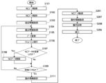
- 4 is a flowchart of a process of the numerical control system according to the first embodiment
- 2 is a configuration example of a processing circuit included in the simulation device according to the first embodiment, when the processing circuit is realized by an arithmetic unit and a memory.
- FIG. 11 is a schematic configuration diagram showing a numerical control system according to a second embodiment.
- 13 is a flowchart of a process of a numerical control system according to a second embodiment.
- FIG. 13 is a schematic configuration diagram showing a numerical control system according to a third embodiment.
- Embodiment 1. 1 is a schematic configuration diagram showing a numerical control system 10 according to a first embodiment.
- the numerical control system 10 includes a simulation device 100 and a numerical control device 200.
- the simulation device 100 includes an operation unit 110 that receives input from a user, a first NC data transmission/reception unit 101 that transmits and receives NC (numerical control) data, a first setting storage unit 107, a simulation execution unit 104, and an operation procedure data creation unit 105.
- the operation unit 110 includes an instruction acquisition unit 102 that acquires instruction information for operating a machine tool in a simulation executed by a simulation execution unit 104, and a setting information acquisition unit 103 that acquires settings required for setup.
- the setting information acquired by the setting information acquisition unit 103 is, for example, information such as the size of the workpiece, the installation position, and the type of tool.
- the first NC data transmission/reception unit 101 acquires setting information related to machining, such as parameters of the numerical control device 200, from the numerical control device 200.
- the first NC data transmission/reception unit 101 is also a first numerical control device data receiving unit.
- the NC data includes setting information that is a setting related to the machine tool, and setting information related to machining and setup.
- Setting information related to machining may include, for example, parameters, work offsets, tool length, etc., but is not limited to these.
- the setting information related to the setup may include, for example, the size of the workpiece, the installation position, the type of tool, etc., but is not limited to these.
- the NC data also includes setup machine tool operation data, which is information for operating the machine tool in the setup.
- the NC data received by the first NC data transmitting/receiving unit includes setup machine tool operation data, which is information for operating the machine tool in the setup before it is changed based on the instruction information described later.
- the first setting storage unit 107 stores the NC data acquired from the first NC data transmission/reception unit 101 and transmits it to the simulation execution unit 104.
- the setting information acquisition unit 103 acquires setting information input by the user and transmits it to the simulation execution unit 104.
- the instruction acquisition unit 102 acquires instruction information given by the user and transmits it to the simulation execution unit 104.
- the instruction information acquired by the instruction acquisition unit 102 is instruction information given by the user to the machine tool during setup work, such as measuring the tool length, pressing a button to set the workpiece installation error, operating a handle, emergency stop, returning to origin, clamping the workpiece, etc.
- the user inputs this instruction information to the instruction acquisition unit 102 by operating a handle, pressing a button, etc. on the display screen of the simulation device 100.
- the instruction information acquired by the instruction acquisition unit 102 is used when changing the setup machine tool operation data included in the NC data.
- the simulation execution unit 104 includes a data modification unit 111, a simulation unit 112, and a judgment unit 113.
- the data modification unit 111 generates modified setup machine tool operation data by modifying the setup machine tool operation data with the acquired instruction information.
- the data modification unit 111 generates modified NC data based on the NC data and the instruction information.
- the simulation unit 112 performs a simulation based on the changed setup machine tool operation data, the setting information acquired by the setting information acquisition unit 103, and the changed NC data.
- the simulations performed by the simulation unit 112 include the setup before machining, a simulation of the operation of the machine tool during the setup, a simulation of the output of the numerical control device 200, a simulation of the shape of the workpiece after machining with the setup changed, and a simulation of the machining state with the setup changed. If the NC data is changed during the simulation, the simulation unit 112 transmits the changed NC data to the first setting storage unit 107.
- the user checks the machining results of the simulation unit 112, and if the results are as desired, inputs OK to the judgment unit 113.
- the judgment unit 113 judges whether or not to perform machining in the simulated setup machine tool operation and changed machining state. If OK is input to the judgment unit 113, the operation procedure data creation unit 105 generates an operation procedure for reproducing the same operation on the machine tool based on the simulation performed by the simulation unit 112, and saves it as operation procedure data 108.
- the operation procedure data creation unit 105 generates and outputs an operation procedure based on the changed setup machine tool operation data or changed NC data determined by the judgment unit 113 to perform machining.
- the operation procedure data 108 is output to the numerical control device 200.
- the simulation execution unit 104 outputs the changed NC data through the first setting storage unit 107 and the first NC data transmission/reception unit 101.
- the first NC data transmission/reception unit 101 is an NC data transmission unit that transmits the changed NC data.
- the numerical control device 200 includes a second NC data transmission/reception unit 201, a second setting retention unit 203, a machine tool operation acquisition unit 202, a display unit 205, an operation procedure screen creation unit 204, and a data acquisition unit 206.
- the second NC data transmission/reception unit 201 acquires the changed NC data output from the simulation device 100.
- the second NC data transmission/reception unit 201 is a second numerical control data receiving unit that receives the changed numerical control data.
- the second setting retention unit 203 acquires and retains the changed NC data from the second NC data transmission/reception unit 201.
- the data acquisition unit 206 acquires the operation procedure data 108 and transmits it to the operation procedure screen creation unit 204.
- the operation procedure screen creation unit 204 creates operation procedure screen data for displaying the operation procedure and transmits the operation procedure screen data to the display unit 205.
- the display unit 205 displays an operation procedure screen based on the acquired operation procedure screen data. That is, the display unit 205 displays an operation procedure based on the changed setup machine tool operation data or changed NC data that has been determined by the determination unit 113 to be the desired result.
- the user operates the machine tool in actual machining by referring to the operation procedure displayed on the display unit 205.
- the machine tool operation acquisition unit 202 acquires NC change data that has changed as a result of the user operating the machine tool in the setup for actual machining, and transmits this data to the second setting storage unit 203.
- the second setting storage unit 203 stores the NC change data acquired from the machine tool operation acquisition unit 202 and the changed NC data acquired from the second NC data transmission/reception unit 201. By storing the changed NC data, the second setting storage unit 203 reflects the changed NC data in the control of the machine tool by the numerical control device 200.
- FIG. 2 is a flowchart of the process of the numerical control system 10 according to the first embodiment.
- the process from step S101 to step S110 is the process of the simulation device 100, and the process from step S201 to step S206 is the process of the numerical control device 200.
- the first NC data transmission/reception unit 101 acquires NC data from the numerical control device 200 (step S101).
- the first setting storage unit 107 stores the NC data received from the first NC data transmission/reception unit 101 and transmits it to the simulation execution unit 104 (step S102).
- step 103 acquires the setting information input by the user and transmits it to the simulation execution unit 104 (step 103).
- the instruction acquisition unit 102 acquires instruction information for operating the machine tool in the simulation and transmits it to the simulation execution unit 104 (step S104).
- step 103 is performed before step 104, but the order may be reversed.
- the data modification unit 111 modifies the setup machine tool operation data of the acquired NC data with the acquired instruction information to generate modified setup machine tool operation data (step S105).
- the simulation unit 112 simulates the operation of the machine tool in setup based on the modified NC data including the modified setup machine tool operation data and the setting information, and simulates the machining state in machining after the setup is completed (step S106).
- step S107 Yes the data change unit 111 sends the changed NC data to the first setting storage unit 107 to update the NC data (step S108). If the NC data is not changed (step S107 No), the process proceeds to step S109.
- the judgment unit 113 judges whether the user has input as to whether the processing is the desired processing or not, and if the processing is the desired processing (step S109 Yes), causes the operation procedure data creation unit 105 to create operation procedure data (step S110). If it is not judged to be the desired processing (step S109 No), the process returns to step S104.
- step S110 For example, if the setup machine tool operation data acquired from the numerical control device 200 includes data on the movement of the tool during setup, and the machine tool is operated using the setup machine tool operation data as is, interference may occur between the machine tool housing and the tool. In such a case, instead of proceeding to step S110 in step S109, return to step S104 and reacquire instruction information for the operation of the machine tool.
- This series of steps which involves acquiring instruction information in step S104, changing the setup machine tool operation data (step S105), and performing a simulation again (step S106), is repeated until interference can be avoided, and if interference can be avoided, select OK in step S109 and proceed to creating operation procedure data (step S110).
- the second NC data transmission/reception unit 201 acquires the NC data from the simulation device 100 and transmits it to the second setting storage unit 203 (step S201).
- the data acquisition unit 206 of the numerical control device 200 acquires the operation procedure data 108 output from the simulation device 100 and transmits it to the operation procedure screen creation unit 204 (step S202).
- the operation procedure screen creation unit 204 creates operation procedure screen data from the acquired operation procedure data 108 and transmits it to the display unit 205 (step S203).
- the operation procedure screen data is data for displaying the operation procedure by which the user should operate the machine tool during setup.
- the display unit 205 displays the operation procedure based on the received operation procedure screen data (step S204).
- the machine tool operation acquisition unit 202 acquires NC change data that has changed as a result of the operation of the machine tool, and transmits it to the second setting storage unit 203 (step S205).
- the operation of the machine tool is the operation that results from the user operating the machine tool according to the operation procedure displayed on the display unit 205.
- the numerical control device 200 performs machining (step S206).
- the operation procedure data creation unit 105 creates an operation procedure based on the modified setup machine tool operation data or modified NC data so that the simulation device 100 can reproduce the machine tool operations performed in the setup simulation.
- a user tries out a large number of setup operations, machining settings, etc. in a simulation, making it difficult for the user to grasp the machine tool operations in the setup that are ultimately judged to be OK.
- an operation procedure is generated based on the modified setup machine tool operation data or modified NC data that is judged to be OK by the judgment unit 113, so the user can operate the machine tool by referring to the operation procedure, reducing the possibility that the user will make a mistake in operating the machine tool during setup.
- the operation unit 110, the simulation execution unit 104, the operation procedure data creation unit 105, the first setting storage unit 107, and the first NC data transmission/reception unit 101 are realized by a processing circuit.
- This processing circuit may be a processor and memory that executes a program stored in a memory, or may be dedicated hardware.
- the processing circuit is also called a control circuit.
- FIG. 3 is a diagram showing an example of the configuration of a processing circuit in the simulation device 100 when the processing circuit is realized by an arithmetic unit and a memory.
- FIG. 3 shows the hardware configuration that realizes the simulation device 100.
- the simulation device 100 has an arithmetic unit 501 which is a processor that performs arithmetic processing, a memory 502 which the arithmetic unit 501 uses as a work area, a storage device 503 which stores programs and data, a communication device 504 which communicates with the numerical control device 200, an input device 505 which accepts input from the user, and a display device 506.
- arithmetic unit 501 which is a processor that performs arithmetic processing
- a memory 502 which the arithmetic unit 501 uses as a work area
- a storage device 503 which stores programs and data
- a communication device 504 which communicates with the numerical control device 200
- an input device 505 which accepts input from the user
- Examples of the arithmetic device 501 include a central processing unit (CPU), a processing device, a microprocessor, or a digital signal processor (DSP).
- An example of the memory 502 is a semiconductor memory.
- the storage device 503 is, for example, a non-volatile or volatile semiconductor memory such as a random access memory (RAM), a read only memory (ROM), a flash memory, an erasable programmable read only memory (EPROM), or an electrically erasable programmable read only memory (EEPROM (registered trademark)), a magnetic disk, a flexible disk, an optical disk, a compact disk, a mini disk, or a digital versatile disk (DVD).
- RAM random access memory
- ROM read only memory
- EPROM erasable programmable read only memory
- EEPROM electrically erasable programmable read only memory
- the programs stored in the storage device 503 are programs that cause the calculation device 501 to execute the procedures or methods executed by the operation unit 110, the simulation execution unit 104, the operation procedure data creation unit 105, the first setting storage unit 107, and the first NC data transmission/reception unit 101.
- the functions of the operation unit 110, the simulation execution unit 104, the operation procedure data creation unit 105, the first setting storage unit 107, and the first NC data transmission/reception unit 101 are realized by the calculation device 501 executing the programs stored in the storage device 503.
- Examples of the input device 505 are some or all of a keyboard, a pointing device, and a mouse.
- the display device 506 is a means for enabling confirmation of the simulation results.
- An example of the display device 506 is a liquid crystal display device.
- the input device 505 and the display device 506 may be integrated together. Specifically, the input device 505 and the display device 506 may be realized by a touch panel.
- the processing circuitry of the simulation device 100 may be configured with dedicated hardware.
- the processing circuitry may be, for example, a single circuit, a composite circuit, a programmed processor, a parallel programmed processor, an ASIC (Application Specific Integrated Circuit), an FPGA (Field Programmable Gate Array), or a combination of these.
- Some of the functions of the operation unit 110, the simulation execution unit 104, the operation procedure data creation unit 105, the first setting storage unit 107, and the first NC data transmission/reception unit 101 may be realized by software or firmware, and the remaining functions may be realized by dedicated hardware.
- the functions of the simulation execution unit 104, operation procedure data creation unit 105, first setting storage unit 107, and first NC data transmission/reception unit 101 can be realized by hardware, software, firmware, or a combination of these.
- parts of the operation unit 110, simulation execution unit 104, operation procedure data creation unit 105, first setting storage unit 107, and first NC data transmission/reception unit 101 may be realized by separate processing circuits.
- the operation procedure data creation unit 105 may be implemented on a server or cloud.
- the user operates the machine tool to obtain the results according to the simulation performed by the simulation execution unit 104, and provides NC change data to the machine tool operation acquisition unit 202.
- This allows the setup to be performed according to the simulation, so the desired machining results can be obtained. For example, it is possible to perform safe machining that can avoid interference, and to achieve highly productive machining that does not require redoing actual machining or reduces the number of times actual machining is performed.
- the operation procedure data creation unit 105 is provided in the simulation device 100, but it may be provided in the numerical control device 200. In that case, the simulation execution unit 104 only needs to transmit to the numerical control device 200 the changed setup machine tool operation data or changed NC data when the determination unit 113 determines that the desired machining is being performed. In this case as well, the same effect can be achieved.
- the operation procedure screen creation unit 204 is provided within the numerical control device 200, it may be provided within the simulation device 100. In that case, the simulation device 100 can transmit the operation procedure screen data created by the operation procedure screen creation unit to the numerical control device 200. In this case as well, the same effect can be achieved.
- the NC data before the simulation is obtained from the numerical control device 200, but the user may also input it. In this case, the same effect can be achieved. Obtaining the data from the numerical control device 200 helps to eliminate input errors.
- the judgment unit 113 judges whether the processing is as desired by the user, but if the pre-input conditions are not met, an alarm may be output.
- the simulation device 100 may be configured to judge whether the pre-input conditions are met. In this case, the same effect can be achieved.
- the first setting storage unit 107 is described as reflecting the changed NC data.
- the NC data may not be changed and the operation procedure data creation unit 105 may output the operation procedure.
- the operation and machining state of the machine tool may be simulated based on changed setup machine tool operation data obtained by changing the setup machine tool operation data, and an operation procedure may be created from the changed NC data or changed setup machine tool operation data, and displayed on the numerical control device 200 to perform a second machining such as precision machining.
- any data changes required after the start of machining can be reproduced by the operator according to the operation procedure at an appropriate timing, such as when switching from rough machining to finishing machining.
- a machine tool operation check unit may be provided which checks whether the same operation as the operating procedure displayed on the display unit 205 has been performed.
- the NC change data may be acquired only when the operation is the same as the operating procedure displayed on the display unit 205, and an alarm may be output, for example, when an operation different from the operating procedure is acquired. In this way, it is possible to further reduce setup mistakes made by the operator.
- Fig. 4 is a schematic configuration diagram showing a numerical control system 10 in the second embodiment. Explanation of the same parts as in the first embodiment will be omitted.
- the numerical control system 10 in the second embodiment will be explained with reference to Fig. 4.
- the second embodiment differs from the first embodiment in that the simulation device 100 does not have the operation procedure data creation unit 105 and an operation data output unit 109 is added, the numerical control device 200 does not have the machine tool operation acquisition unit 202, the operation procedure screen creation unit 204, and the display unit 205, and an operation reflection unit 207 is added.
- the operation data output unit 109 saves data used to simulate the operation of the machine tool in the setup executed by the simulation execution unit 104 as operation information 114. Specifically, the changed setup machine tool operation data or changed NC data generated by the data modification unit 111 is saved as operation information 114.
- the data acquisition unit 206 of the numerical control device 200 receives the operation information 114 from the simulation device 100 and transmits it to the operation reflection unit 207.
- the data acquisition unit 206 in the second embodiment is an operation data acquisition unit.
- the operation reflection unit 207 controls the actual machine tool based on the operation information 114.
- FIG. 5 is a flowchart of the processing of the numerical control system 10 according to the second embodiment. Explanations of the same parts as in the first embodiment will be omitted. Compared to the flowchart in the first embodiment, this differs in that step S110 and steps S202 to S205 are not present, and steps S111, S207, and S208 have been added. Step S111 is the operation of the simulation device 100, and steps S207 and S208 are the operation of the numerical control device 200.
- step S109 if it is determined in step S109 that actual machining will be performed, the operation data output unit 109 saves and outputs the changed setup machine tool operation data or changed NC data as operation information 114 (step S111).
- the data acquisition unit 206 of the numerical control device 200 acquires the operation information 114 and transmits it to the operation reflection unit 207 (step S207).
- the order of the operations in steps S201 and S207 is not limited to this and may be reversed.
- the operation reflection unit 207 controls the machine tool based on the operation information 114 to perform the setup (step S208). That is, the operation reflection unit 207 reflects the changed setup machine tool operation data or the changed NC data in the control of the machine tool.
- the operation procedure was shown in the numerical control device 200 so that the user could easily reproduce the operation of the machine tool during setup performed by the simulation device 100.
- the numerical control device 200 acquires the changed setup machine tool operation data or changed NC data generated by the data modification unit 111 as operation information 114 and reflects this in the control of the machine tool by the operation reflection unit 207, eliminating the need for the user to operate the machine tool during setup. This eliminates the effort and operational errors required of the user to operate the machine tool. In other words, it is possible to reliably execute machining that is similar to the machining results of the simulation device 100.
- the operation information 114 is changed setup machine tool operation data or changed NC data, it may be pre-change setup machine tool operation data, and may be the operation data of the machine tool used in the simulation when the judgment unit 113 judges that machining should be performed. Even in this case, the operation reflection unit 207 reflects the control of the machine tool, so that the user does not need to operate the machine tool during setup, and machining similar to the machining result of the simulation device 100 can be reliably performed.
- the first embodiment may have a configuration for displaying operation procedures, and may further have the operation data output unit 109 and operation reflection unit 207 of the present embodiment.
- the operation data output unit 109 and operation reflection unit 207 of the present embodiment.
- the automatically reflected parts have the above-mentioned effects, and the parts showing the operation procedures have the same effects as in the first embodiment.
- Embodiment 3. 6 is a schematic configuration diagram showing a numerical control system 10 according to a third embodiment. The difference is that another numerical control device 300 and a tablet terminal 400 are added to the configuration of the first or second embodiment. Explanations of the same parts as those of the first and second embodiments will be omitted.
- the configuration of the other numerical control device 300 is the same as that of the numerical control device 200.
- the second NC data transmission/reception unit 201 in the numerical control device 200 of embodiment 3 transmits modified NC data to the third NC data transmission/reception unit 301 in the other numerical control device 300.
- the third NC data transmission/reception unit 301 in the other numerical control device 300 receives modified NC data from the numerical control device 200 and stores it in the third setting storage unit 303.
- the data acquisition unit 206 of the numerical control device 200 of embodiment 3 transmits the operation information 114 or operation procedure data to the data acquisition unit 306 of the other numerical control device 300 in addition to the processing of the data acquisition unit 206 of embodiment 1 or embodiment 2.
- the data acquisition unit 306 of the other numerical control device 300 acquires the operation information 114 or operation procedure data 108 from the numerical control device 200 in addition to the same processing as the data acquisition unit 206 of embodiment 1 or embodiment 2.
- the tablet terminal 400 also includes a data acquisition unit 206, an operation procedure screen creation unit 204, and a display unit 205 similar to those of the numerical control device 200 of the first embodiment.
- the data acquisition unit 206 of the tablet terminal 400 acquires operation procedure data 108 from the simulation device 100 or the numerical control device 200, and displays the operation procedure on the display unit 205 of the tablet terminal 400.
- the tablet terminal 400 is connected to the numerical control device 200, but may also be connected to another numerical control device 300.
- the simulation device 100 transmits to the numerical control device 200 the operation information 114 or operation procedure data 108 for reproducing the operation of the machine tool during setup as simulated, but the numerical control devices 200 can also transmit the operation information 114 or operation procedure data 108 between each other, so in addition to the effect of being able to perform setup as simulated using the operation procedure of embodiment 1 and the effect of eliminating the need to operate the machine tool during setup by reflecting the operation of embodiment 2, the effect of being able to perform machining efficiently using multiple numerical control devices is achieved. Also, since the operation procedure can be displayed not only on the numerical control device but also on a tablet terminal, it is possible to operate the machine tool while moving around with the tablet terminal, for example, making user operation even easier compared to embodiments 1 and 2.
- one other numerical control device 300 and one tablet terminal 400 are provided, but there may be multiple other numerical control devices 300 and tablet terminals 400.
- both the other numerical control device 300 and the tablet terminal 400 are provided, but the configuration may include only the other numerical control device 300, or only the tablet terminal 400.
Landscapes
- Engineering & Computer Science (AREA)
- Human Computer Interaction (AREA)
- Manufacturing & Machinery (AREA)
- Physics & Mathematics (AREA)
- General Physics & Mathematics (AREA)
- Automation & Control Theory (AREA)
- Numerical Control (AREA)
Priority Applications (4)
| Application Number | Priority Date | Filing Date | Title |
|---|---|---|---|
| PCT/JP2023/004113 WO2024166239A1 (ja) | 2023-02-08 | 2023-02-08 | 数値制御システム、数値制御プログラムおよび数値制御方法 |
| DE112023004536.4T DE112023004536T5 (de) | 2023-02-08 | 2023-02-08 | NC-System, NC-Programm und NC-Verfahren |
| CN202380087005.XA CN120435694A (zh) | 2023-02-08 | 2023-02-08 | 数控系统、数控程序及数控方法 |
| JP2023534698A JP7333893B1 (ja) | 2023-02-08 | 2023-02-08 | 数値制御システム、数値制御プログラムおよび数値制御方法 |
Applications Claiming Priority (1)
| Application Number | Priority Date | Filing Date | Title |
|---|---|---|---|
| PCT/JP2023/004113 WO2024166239A1 (ja) | 2023-02-08 | 2023-02-08 | 数値制御システム、数値制御プログラムおよび数値制御方法 |
Publications (1)
| Publication Number | Publication Date |
|---|---|
| WO2024166239A1 true WO2024166239A1 (ja) | 2024-08-15 |
Family
ID=87654360
Family Applications (1)
| Application Number | Title | Priority Date | Filing Date |
|---|---|---|---|
| PCT/JP2023/004113 Ceased WO2024166239A1 (ja) | 2023-02-08 | 2023-02-08 | 数値制御システム、数値制御プログラムおよび数値制御方法 |
Country Status (4)
| Country | Link |
|---|---|
| JP (1) | JP7333893B1 (https=) |
| CN (1) | CN120435694A (https=) |
| DE (1) | DE112023004536T5 (https=) |
| WO (1) | WO2024166239A1 (https=) |
Cited By (1)
| Publication number | Priority date | Publication date | Assignee | Title |
|---|---|---|---|---|
| CN120019340A (zh) * | 2024-03-22 | 2025-05-16 | 发那科株式会社 | 模拟装置以及计算机程序 |
Citations (5)
| Publication number | Priority date | Publication date | Assignee | Title |
|---|---|---|---|---|
| JPS62140743A (ja) * | 1985-12-13 | 1987-06-24 | Hitachi Seiki Co Ltd | 自動加工機における加工情報設定装置 |
| JPH0679591A (ja) * | 1992-06-10 | 1994-03-22 | Yamazaki Mazak Corp | シミュレーション機能を備えた自動加工装置 |
| JPH06124113A (ja) * | 1992-10-14 | 1994-05-06 | Mori Seiki Co Ltd | 対話形数値制御装置 |
| JP2008112269A (ja) * | 2006-10-30 | 2008-05-15 | Okuma Corp | 加工シミュレーションシステム |
| JP2016040659A (ja) * | 2014-08-12 | 2016-03-24 | ファナック株式会社 | 加工シミュレーション装置 |
Family Cites Families (2)
| Publication number | Priority date | Publication date | Assignee | Title |
|---|---|---|---|---|
| JP2753364B2 (ja) * | 1990-02-23 | 1998-05-20 | オークマ株式会社 | 数値制御情報作成装置 |
| WO2018092300A1 (ja) * | 2016-11-21 | 2018-05-24 | 三菱電機株式会社 | シミュレーション装置、シミュレーションシステム、シミュレーション方法およびシミュレーションプログラム |
-
2023
- 2023-02-08 WO PCT/JP2023/004113 patent/WO2024166239A1/ja not_active Ceased
- 2023-02-08 JP JP2023534698A patent/JP7333893B1/ja active Active
- 2023-02-08 DE DE112023004536.4T patent/DE112023004536T5/de active Pending
- 2023-02-08 CN CN202380087005.XA patent/CN120435694A/zh active Pending
Patent Citations (5)
| Publication number | Priority date | Publication date | Assignee | Title |
|---|---|---|---|---|
| JPS62140743A (ja) * | 1985-12-13 | 1987-06-24 | Hitachi Seiki Co Ltd | 自動加工機における加工情報設定装置 |
| JPH0679591A (ja) * | 1992-06-10 | 1994-03-22 | Yamazaki Mazak Corp | シミュレーション機能を備えた自動加工装置 |
| JPH06124113A (ja) * | 1992-10-14 | 1994-05-06 | Mori Seiki Co Ltd | 対話形数値制御装置 |
| JP2008112269A (ja) * | 2006-10-30 | 2008-05-15 | Okuma Corp | 加工シミュレーションシステム |
| JP2016040659A (ja) * | 2014-08-12 | 2016-03-24 | ファナック株式会社 | 加工シミュレーション装置 |
Cited By (1)
| Publication number | Priority date | Publication date | Assignee | Title |
|---|---|---|---|---|
| CN120019340A (zh) * | 2024-03-22 | 2025-05-16 | 发那科株式会社 | 模拟装置以及计算机程序 |
Also Published As
| Publication number | Publication date |
|---|---|
| JPWO2024166239A1 (https=) | 2024-08-15 |
| CN120435694A (zh) | 2025-08-05 |
| DE112023004536T5 (de) | 2025-08-28 |
| JP7333893B1 (ja) | 2023-08-25 |
Similar Documents
| Publication | Publication Date | Title |
|---|---|---|
| US7174225B2 (en) | Method and system for simulating processing of a workpiece with a machine tool | |
| CN112508763B (zh) | 激光加工方法、激光加工设备及存储介质 | |
| US11345026B2 (en) | Robot program generation apparatus | |
| JP2005066797A (ja) | ロボットプログラム位置修正装置 | |
| US10114363B2 (en) | Numerical controller capable of partial correction of machining cycle | |
| US20200130184A1 (en) | Machine tool system | |
| US9727442B2 (en) | Engineering tool, program editing device, and program editing system | |
| JP2010140359A (ja) | シミュレーション装置 | |
| KR101889631B1 (ko) | 시퀀스 프로그램 작성 지원 장치 | |
| US11314230B2 (en) | Machining program generation support device | |
| US10228681B2 (en) | Method of generating a machining program | |
| US20190012168A1 (en) | Program generating apparatus | |
| WO2024166239A1 (ja) | 数値制御システム、数値制御プログラムおよび数値制御方法 | |
| KR102198204B1 (ko) | 시뮬레이션 장치 | |
| KR101468751B1 (ko) | 그래픽 기반의 사용자 인터페이스를 갖는 수치제어시스템 | |
| KR20180009344A (ko) | 프로그램 생성 장치 및 그 방법 | |
| CN110303495A (zh) | 提高操作性的综合模拟系统 | |
| WO2020012881A1 (ja) | プログラム開発装置、およびコントローラ | |
| JP6632692B1 (ja) | 制御プログラム作成支援ツール及び制御プログラムの作成方法 | |
| KR101610386B1 (ko) | 컴퓨터 수치 제어 공작기계에서 가공 대화형 프로그램을 이용한 가공 형상 입력 장치 및 방법 | |
| US20130159979A1 (en) | Apparatus and method for performing emulation on robotic application | |
| US20250298722A1 (en) | Simulation system | |
| CN119365835B (zh) | 仿真程序产品、仿真方法及仿真装置 | |
| JP7504324B1 (ja) | 支援プログラム、支援装置、支援システム及び支援方法 | |
| JP7398856B2 (ja) | プログラム作成支援装置 |
Legal Events
| Date | Code | Title | Description |
|---|---|---|---|
| WWE | Wipo information: entry into national phase |
Ref document number: 2023534698 Country of ref document: JP |
|
| 121 | Ep: the epo has been informed by wipo that ep was designated in this application |
Ref document number: 23921071 Country of ref document: EP Kind code of ref document: A1 |
|
| WWE | Wipo information: entry into national phase |
Ref document number: 202380087005.X Country of ref document: CN |
|
| WWE | Wipo information: entry into national phase |
Ref document number: 112023004536 Country of ref document: DE |
|
| WWP | Wipo information: published in national office |
Ref document number: 202380087005.X Country of ref document: CN |
|
| WWP | Wipo information: published in national office |
Ref document number: 112023004536 Country of ref document: DE |
|
| 122 | Ep: pct application non-entry in european phase |
Ref document number: 23921071 Country of ref document: EP Kind code of ref document: A1 |