WO2024166197A1 - パイプコネクタ、パイプ接続システム及びパイプ接続方法 - Google Patents
パイプコネクタ、パイプ接続システム及びパイプ接続方法 Download PDFInfo
- Publication number
- WO2024166197A1 WO2024166197A1 PCT/JP2023/003940 JP2023003940W WO2024166197A1 WO 2024166197 A1 WO2024166197 A1 WO 2024166197A1 JP 2023003940 W JP2023003940 W JP 2023003940W WO 2024166197 A1 WO2024166197 A1 WO 2024166197A1
- Authority
- WO
- WIPO (PCT)
- Prior art keywords
- pipe
- connector
- female connector
- torque transmission
- male connector
- Prior art date
- Legal status (The legal status is an assumption and is not a legal conclusion. Google has not performed a legal analysis and makes no representation as to the accuracy of the status listed.)
- Ceased
Links
Images


Classifications
-
- E—FIXED CONSTRUCTIONS
- E21—EARTH OR ROCK DRILLING; MINING
- E21B—EARTH OR ROCK DRILLING; OBTAINING OIL, GAS, WATER, SOLUBLE OR MELTABLE MATERIALS OR A SLURRY OF MINERALS FROM WELLS
- E21B7/00—Special methods or apparatus for drilling
- E21B7/12—Underwater drilling
- E21B7/132—Underwater drilling from underwater buoyant support
Definitions
- the present invention relates to a pipe connector, a pipe connection system, and a pipe connection method.
- a method for performing seabed drilling from a ship involves equipping the tip of a drill pipe with a drilling blade, fitting a detachable hole-mouth end device to the drill pipe directly above the drilling blade, and lowering the drill pipe to the seabed with a hole-mouth end device attached to the hole-mouth support tube.
- the drill pipe is detached from the hole-mouth end device, and the drill pipe is lowered as the drilling blade rotates, allowing continuous drilling to be performed.
- the device when the water depth is shallower than 3000 m, for example, the device is lowered by a remote control and when the device hits the seabed, the whole drill pipe is rotated to separate the main body and the shank of the device. The separated drill pipe is moved up and down relative to the main body with the shank still attached.
- the structure does not detach the hole mouth tip device from the hole mouth support tube as in the conventional method, the hole mouth tip device attached to the drill pipe is detached from the hole mouth support tube, the drill pipe together with the hole mouth tip device is temporarily pulled onto the ship, and the drill pipe with the hole mouth tip device removed is then placed again inside the hole mouth support tube installed on the seabed and drilling is performed, which eliminates the work process involved in rearranging the pipe by raising and lowering it, and has the advantage of reducing work time and costs.
- the conventional method of using a drill hole tip device to separate the main body and shaft of the drill hole tip device by rotating them was limited to installation work at shallow depths of less than 3000m accompanied by a remote control body.
- the distance between the suspension point of the drill pipe on the ship and the seabed becomes very large, and the total length of the drill pipe becomes long, so it is easy for the number of rotations of the drill pipe on the ship to not match the number of rotations at the release point on the seabed, making control very difficult.
- the present invention was made in consideration of the above-mentioned problems, and aims to provide a pipe connector, a pipe connection system, and a pipe connection method that can efficiently connect and disconnect a male connector to a female connector, and a female connector to a housing, without rotating the pipe.
- a pipe connector is a pipe connector that detachably connects an underwater function unit that performs a predetermined operation underwater to the lower end of a pipe, and includes a male connector provided at the lower end of the pipe, a female connector that is detachably connected to the lower end of the male connector and to which the underwater function unit is connected, and a housing that accommodates the male connector and the female connector, wherein the male connector has a torque transmission unit that transmits rotational torque to the female connector, and the female connector is configured to transmit torque to the torque transmission unit.
- the housing has a torque transmission receiving part that receives the torque from the male connector and a first holding mechanism that holds the female connector so that it cannot move up and down and is detachable relative to the male connector, and the housing is provided with a second holding mechanism that holds the female connector so that it cannot move up and down and is detachable, and when the male connector and the female connector are connected by the first holding mechanism, the torque transmission part and the torque transmission receiving part are connected, and when the second holding mechanism is released, the male connector and the female connector that are integrally connected are rotatably arranged.
- the male connector and the female connector can be connected in a state where they are held by the first holding mechanism so that they cannot move up and down and can be attached and detached.
- the torque transmission part and the torque transmission receiving part are connected, so that the torque of the pipe can be transmitted to the female connector via the male connector.
- the torque of the female connector can be transmitted to an underwater functional part, such as a drilling blade, attached below the female connector, to effectively apply a rotational force.
- the female connector can be connected in a state where it is held by the second holding mechanism so that it cannot move up and down and can be attached and detached from the housing. That is, the connector in which the male connector and the female connector are connected together is held in a state where it is restricted from moving up and down relative to the housing. Then, when the second holding mechanism releases the holding of the housing and the female connector, the male connector and the female connector connected together become rotatable and can also move up and down. Therefore, after the housing holding the female connector is lowered from the ship to the seabed first, the male connector lowered from the ship can be connected to the female connector, and work can be performed using the underwater function unit connected to the lower end of the female connector.
- the first retaining mechanism may be characterized by having a retaining portion that is movable in a radial direction perpendicular to the pipe axis and presses the male connector from the outer periphery, and a locking mechanism that is provided on the outer periphery of the retaining portion and is movable in the vertical direction between a locked position where the retaining portion is pressed from the outer periphery and an unlocked position that is vertically displaced from the locked position.
- the holding portion of the first holding mechanism provided on the female connector when the holding portion of the first holding mechanism provided on the female connector is pressed from the outer periphery, the holding portion holds the male connector so that it cannot move up and down and can be attached and detached.
- the pressing force of the holding portion is moved up and down by the locking mechanism to switch between the locked position and the unlocked position, so unless the locking mechanism is operated, the connector together with the pipe will not move to the unlocked position due to the swaying of the hull, and the connection between the male connector and the female connector can be prevented from coming loose.
- the locking mechanism may have a pressing part that presses the holding part from the outer periphery, a ring-shaped cam ring that integrally supports the pressing part from below and has a recess that opens outward in the pipe radial direction, and a cam head that is rotatable in a circumferential direction about the pipe axis inside the recess of the cam ring and can move forward and backward in a radial direction perpendicular to the pipe axis, and the cam ring and the pressing part may move up and down depending on the rotation angle of the cam head rotating inside the cam ring, switching between the locked position and the unlocked position.
- the cam ring is displaced vertically according to the position of the rotation angle of the cam head, which is disposed eccentrically with respect to the rotation axis of the cam head.
- the pressing portion which is supported from below by the cam ring and presses the holding portion, can be moved up and down by the locking mechanism to switch between the locked position and the unlocked position.
- the cam ring is configured so that it does not move up and down unless the cam head is rotated, and the pressing portion does not easily come off the holding portion. Therefore, rocking of the hull will not cause the pressing portion to move into the unlocked position, preventing the male connector and female connector from becoming disconnected.
- the torque transmission portion may have a sawtooth-like first engagement tooth with an inclined portion that intersects with the pipe axis on the upstream side in the pipe rotation direction around the entire circumferential direction around the pipe axis, and the torque transmission receiving portion may have a second engagement tooth that meshes with the first engagement tooth of the torque transmission portion.
- the male connector and female connector are held by the first holding mechanism so that they cannot move up and down, and the first locking teeth of the male connector and the second locking teeth of the female connector mesh and connect in the direction of rotation of the pipe, so that the torque caused by the rotation of the pipe can be reliably transmitted to the female connector via the male connector.
- a pipe connection system is a pipe connection system including a pipe connector according to any one of (1) to (4), characterized in that the system includes a pipe extending from above the water into the water, an underwater function unit that performs a predetermined operation underwater, and the pipe connector that detachably connects the underwater function unit to the lower end of the pipe.
- the pipe connection system according to the above aspect provides the same effects as those provided by the pipe connector described in any one of (1) to (4) above.
- a pipe connection method is a pipe connection method using a pipe connector according to any one of (1) to (4), characterized in that it includes the steps of: holding the housing by the second holding mechanism so that it cannot move up and down relative to the female connector and so that it can be attached and detached; connecting the torque transmission part of the male connector to the torque transmission receiving part of the female connector; holding the female connector by the first holding mechanism so that it cannot move up and down relative to the male connector and so that it can be attached and detached; and releasing the second holding mechanism when the male connector and the female connector are connected by the first holding mechanism and the torque transmission part and the torque transmission receiving part are connected, so that the male connector and the female connector, which are integrally connected, can rotate.
- the pipe connection method according to the above aspect provides the same effects as those provided by the pipe connector described in any one of (1) to (4) above.
- the pipe connector, pipe connection system, and pipe connection method of the present invention allow efficient connection and disconnection between the male connector and the female connector, and between the female connector and the housing, without rotating the pipe.
- FIG. 2 is a vertical cross-sectional view showing a schematic configuration of the pipe connection system, illustrating a first holding mechanism.
- FIG. 2 is a vertical cross-sectional view of the pipe connection system shown in FIG. 1 as seen from another direction in the rotational direction, showing a second retaining mechanism.
- FIG. 2 is an enlarged view of a main portion of the pipe connection system.
- FIG. 4 is a vertical cross-sectional view showing a state in which the connected male connector and female connector are being detached from the housing in FIG. 3 . 4 is an enlarged view of a main portion of the connection between the male connector and the female connector.
- FIG. 13 is an enlarged view of a main portion for explaining a holding state by a second holding mechanism.
- FIG. 7 is an enlarged view of a main part for explaining a holding state by a second holding mechanism subsequent to FIG. 6;
- FIG. 8 is an enlarged view of a main part for explaining a holding state by a second holding mechanism subsequent to FIG. 7 .
- FIG. FIG. 2 is a longitudinal cross-sectional view of a male connector.
- FIG. 2 is a partially sectional perspective view showing a main portion of a male connector.
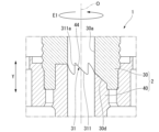
- FIG. 4 is an enlarged view of a main portion of a connecting portion between a torque transmission portion and a torque transmission receiving portion, showing the state before the connection.
- FIG. 13 is an enlarged view of a main portion of the connecting portion between the torque transmission portion and the torque transmission receiving portion, showing the state after the connection is completed; 4 is a partially sectional perspective view showing a main portion of an outer tubular portion of the female connector.
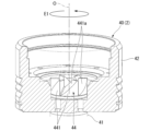
- FIG. 1 is a perspective view of a female connector seen obliquely from above.
- 11 is a vertical cross-sectional view showing a state in which the first holding mechanism is in an unlocked position.
- FIG. 11 is a vertical cross-sectional view showing a state in which the first holding mechanism is in a locked position;
- FIG. FIG. 13 is a perspective view showing the eccentric cam of the first holding mechanism, with the cam head in the 12 o'clock position;
- FIG. 13 is a perspective view showing the eccentric cam of the first holding mechanism, with the cam head at the 3 o'clock position;
- FIG. 13 is a perspective view showing the eccentric cam of the first holding mechanism, with the cam head at the 6 o'clock position;
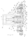
- the pipe connection system 1 of this embodiment is a system used to efficiently connect a drill pipe 10 and an underwater function unit when performing operations such as drilling the seabed by lowering a drill pipe 10 (pipe) from a vessel (not shown) such as an underwater exploration vessel to the seabed, attaching an underwater function unit to the lower end of the drill pipe 10, and excavating the seabed.
- the pipe connection system 1 is a system for connecting pipes equipped with a pipe connector 2.
- the pipe connection system 1 includes a drill pipe 10 extending from the sea to underwater, a drilling blade 11 (underwater functional part) that performs a predetermined operation underwater, and a pipe connector 2 that detachably connects the drilling blade 11 to the lower end of the drill pipe 10.
- the pipe connector 2 detachably connects a drilling blade 11 , which is used for drilling operations in the sea, to the lower end of the drill pipe 10 .
- the pipe connector 2 comprises a male connector 30 provided at the lower end of the drill pipe 10, a female connector 40 that is detachably connected to the lower end of the male connector 30 and has a drilling blade 11 connected below, and a housing 50 that accommodates the male connector 30 and the female connector 40.
- the housing 50 is fitted over the female connector 40 from above.
- the male connector 30 is inserted into the housing 50 from above, and the lower end of the male connector 30 is connected to the upper end of the female connector 40 attached to the housing 50.
- the housing 50 of the pipe connector 2 and the male connector 30 and female connector 40 housed in the housing 50 are each arranged coaxially in the up-down direction Y (vertical direction) underwater, with the central axis coinciding with the center of the pipe connector 2, which is referred to as the pipe axis O.
- the direction perpendicular to the pipe axis O is referred to as the radial direction
- the direction going around the pipe axis O as viewed from the direction of the pipe axis O is referred to as the circumferential direction.
- the drill pipes 10 are hollow steel pipes, each 9 m long and threaded at both ends, and are lowered by connecting multiple pieces together.
- a drilling blade 11 is attached to the lower end of the drill pipe 10, which is located at the bottom, via a pipe connector 2. The drilling blade 11 rotates as the drill pipe rotates, allowing the seabed to be excavated.
- the drill pipe 10 When drilling the seabed, the drill pipe 10 is rotated by the driving force of the top drive (not shown) on the ship, and the seabed is excavated by the rotating drilling blade 11, and the excavated soil is mixed with the supplied seawater. The excavated soil generated by the drilling blade 11 is then discharged into the sea together with the mixed mud water.
- the housing 50 holds the connected male connector 30 and female connector 40 in a rotatable state but in a state where they cannot move in the vertical direction Y.
- an upper cylinder portion 50A, a middle cylinder portion 50B, and a lower cylinder portion 50C are arranged in this order from top to bottom with the cylinder axis facing the vertical direction Y.
- the middle cylinder portion 50B and the lower cylinder portion 50C have a housing portion 51 that fits over the female connector 40 from above and holds it in a predetermined position.
- the part of the inside of the housing portion 51 that is located at the middle cylinder portion 50B becomes the connection portion of the male connector 30 and the female connector 40.
- the upper cylinder portion 50A forms an introduction path 52 for fitting the male connector 30 from above into the female connector 40 housed in the housing portion 51.
- the inner diameter of the accommodating section 51 is approximately equal to the outer diameter of the female connector 40.
- An opening hole 51a that communicates with the introduction passage 52 is formed at the upper end of the accommodating section 51.
- the inner diameter of the opening hole 51a is approximately equal to the outer diameter of the male connector 30.
- the housing 50 is also provided with a second holding mechanism 70 that prevents the female connector 40 from moving in the vertical direction Y and holds the female connector 40 in a detachable manner, as shown in FIG. 3.
- a second holding mechanism 70 that prevents the female connector 40 from moving in the vertical direction Y and holds the female connector 40 in a detachable manner, as shown in FIG. 3.
- the male connector 30 and female connector 40 that are integrally connected become rotatable and movable up and down, as shown in FIG. 4.
- the second retaining mechanism 70 includes a second retaining portion 71 that can engage with the outer peripheral surface of the female connector 40 (the outer peripheral surface 42a of the outer tube portion 42), and a retaining drive device 72 that drives the second retaining portion 71 so that it can engage with the female connector 40.
- First through holes 53 are formed at an intermediate portion of the middle cylinder portion 50B in the up-down direction Y, the first through holes 53 being spaced apart in the circumferential direction and penetrating the wall of the middle cylinder portion 50B in the thickness direction.
- a second holding portion 71 of the second holding mechanism 70 is provided in the first through hole 53 so as to be movable forward and backward in the through direction (the radial direction X perpendicular to the pipe axis O).
- the second retaining portion 71 is provided in a state where it is pressed from the outside in the radial direction so as to protrude from the first through hole 53 towards the accommodating portion 51 of the middle tube portion 50B.
- a first uneven locking portion 711 that locks into the second uneven locking portion 423 (described later) of the female connector 40 is formed on the holding surface of the second retaining portion 71.
- the first uneven locking portion 711 has multiple notches cut upward and arranged in the vertical direction, and these notches extend around the entire circumference in the circumferential direction (see Figure 5). The first uneven locking portion 711 locks into any position in the circumferential direction of the second uneven locking portion 423 of the female connector 40.
- the holding and driving device 72 includes a push shaft 74 having a second holding portion 71 at its axial tip portion 74a, a rotation mechanism portion 75 which screws into a base end thread portion 74b formed on the outer circumferential surface of the base end portion of the push shaft 74 to rotate the push shaft 74 axially and moves it forward and backward in a radial direction X perpendicular to the pipe axis O, a position detection sensor 76 which detects the axial position of the push shaft 74, and a case 77 which houses the push shaft 74, the rotation mechanism portion 75, and the position detection sensor 76.
- the central axis of the push shaft 74 is referred to as a first axis C1.
- a support base 78 for supporting the push shaft 74 and the case 77 is fixed to the outer circumferential surface 50 a of the housing 50 .
- the rotation mechanism 75 includes a female thread engaging portion 751 that screws into the base end thread portion 74b of the push shaft 74.
- the rotation mechanism 75 rotates in both forward and reverse directions around the first axis C1 together with the female thread engaging portion 751. That is, the rotation mechanism 75 rotates in one direction to rotate the push shaft 74 forward and move it forward in the first axis C1 direction toward the second concave-convex locking portion 423 of the female connector 40, and rotates in the other direction to rotate the push shaft 74 forward and move it forward in the first axis C1 direction toward the second concave-convex locking portion 423 of the female connector 40.
- the rotation mechanism 75 is provided with its rotation axis aligned with the first axis C1 of the push shaft 74, and can be rotated by operating it from an external ROV, for example.
- the support base 78 has an axial hole 78a through which the push shaft 74 is inserted, and an open recess 78b facing the outer circumferential surface 50a of the housing 50.
- the axial hole 78a and the open recess 78b are formed coaxially.
- the case 77 is formed in a cylindrical shape, one end in the direction of the first axis C1 is fixed to a support base 78, and the rotation mechanism 75 is attached to close the opening at the other end.
- the push shaft 74 is rotatably supported on the support base 78 with the axial direction of the push shaft 74 oriented parallel to the radial direction X.
- the shaft tip 74a of the push shaft 74 engages with an engagement recess 712 formed in the second holding part 71.
- the push shaft 74 rotates about the first axis C1 and moves back and forth in the first axis C1 direction.
- the second holding part 71 engaged with the shaft tip 74a of the push shaft 74 pushes and pulls in the first axis C1 direction (radial direction X).
- a convex portion 741 that can be detected by a position detection sensor 76 is fixed to the peripheral surface of the base end screw portion 74b side of the push shaft 74.
- the position detection sensor 76 is fixed to the case 77 so that the detection portion 76a is disposed in a direction perpendicular to the first axis C1 of the push shaft 74.
- the convex portion 741 is provided around the entire circumference of the push shaft 74.
- the position detection sensor 76 can detect the position of the convex portion 741 that moves along with the movement of the push shaft 74 in the direction of the first axis C1.
- a second through hole 54 is formed in the middle of the middle tube portion 50B in the up-down direction Y at a position circumferentially offset from the first through hole 53 described above, and penetrates the tube wall of the middle tube portion 50B in the thickness direction at a circumferentially spaced position.
- a part of the first holding mechanism 60 of the female connector 40 (such as a cam head 64) described later is provided in the second through hole 54 so as to be movable back and forth in the penetration direction and rotatable (see FIG. 15 and FIG. 16).
- the male connector 30 is formed in a cylindrical shape having an axial hole 30a.
- a step 30b which is slightly narrower at the lower side, is formed on the upper outer surface of the male connector 30 around the entire circumference. This step 30b is placed from above on the upper inner peripheral edge 40a of the female connector 40 when the male connector 30 is joined to the female connector 40. In other words, when the step 30b is placed on the upper inner peripheral edge 40a of the female connector 40, the male connector 30 and the female connector 40 are positioned at the position where they are connected.
- the lower peripheral surface 30c of the male connector 30 has an engagement uneven portion 32 formed along the vertical direction Y.
- the engagement uneven portion 32 can engage with a first engagement uneven portion 61a of the first retaining portion 61 described below.
- the engagement uneven portion 32 is configured with a number of grooves that extend around the entire circumference and are arranged in the vertical direction Y.
- the male connector 30 has a torque transmission portion 31 that transmits rotational torque to a torque transmission receiving portion 44 of the female connector 40, which will be described later.
- the torque transmission portion 31 has sawtooth-like first engagement teeth 311 with inclined portions 311a that intersect with the pipe axis O on the upstream side in the pipe rotation direction, all around the circumference of the torque transmission portion 31 around the pipe axis O.
- the male connector 30 has an enlarged diameter portion 30d at the lower end of the axial hole 30a, the hole diameter of which gradually increases downward.
- the first engagement teeth 311 are formed on this enlarged diameter portion 30d.
- the inclined portions 311a of each first engagement tooth 311 are inclined downward as they approach the rotation direction E1 of the male connector 30.
- the inclined portions 311a of the multiple first engagement teeth 311 arranged in the circumferential direction face a fixed direction in the circumferential direction.
- the female connector 40 is arranged so that it can be accommodated in the accommodation portion 51 of the housing 50.
- the female connector 40 is arranged so that it can be accommodated by covering the housing 50 from above, and when accommodated in a predetermined position, it is fixed to the housing 50 by the second holding mechanism 70.
- the female connector 40 comprises a shaft portion 41 having a through hole 41a, an outer tube portion 42 provided at the upper end of the shaft portion 41 and having a larger diameter than the shaft portion 41, and a torque transmission receiving portion 44 that receives the torque transmission portion 31 of the male connector 30 in a manner that allows torque transmission. Furthermore, the female connector 40 is provided with a first holding mechanism 60 that holds the male connector 30 provided on the outer tube portion 42 and connected to the female connector 40 (see Figures 3 to 5). That is, in the pipe connection system 1, the torque transmission portion 31 and the torque transmission receiving portion 44 are connected with the male connector 30 and the female connector 40 connected by the first holding mechanism 60.
- the drilling blade 11 is connected to the lower end 41b of the shaft portion 41. That is, the drill pipe 10 can also be connected to the lower end 41b of the shaft portion 41.
- the shaft portion 41 is provided integrally with the outer cylinder portion 42 in a state in which it penetrates a bottom wall 421 of the outer cylinder portion 42.
- the above-mentioned torque transmission receiving portion 44 is provided at the upper end of the shaft portion 41 (see FIGS. 4 and 5).
- the outer tube portion 42 is a cylinder with a bottom, and is arranged coaxially with the shaft portion 41 with the upper end portion of the shaft portion 41 passing through it.
- the outer tube portion 42 has a bottom wall 421 and a side wall 422.
- the upper end 422a of the side wall 422 is located above the torque transmission receiving portion 44 of the shaft portion 41.
- a connection is arranged in which the male connector 30 is housed and connected to the female connector 40.
- the outer peripheral surface 42a of the outer tube portion 42 is provided with a second concave-convex locking portion 423 at a portion in the vertical direction Y, to which the second retaining portion 71 of the second retaining mechanism 70 is locked.
- the second concave-convex locking portion 423 has a number of notches cut upwardly arranged in the vertical direction, and these notches extend around the entire circumference in the circumferential direction.
- the second retaining portion 71 which is pressed radially inward, is locked at any circumferential position of the second concave-convex locking portion 423.
- the torque transmission receiving portion 44 has second engagement teeth 441 that mesh with the first engagement teeth 311 of the torque transmission portion 31 shown in Figures 11 and 12 over the entire circumferential direction around the pipe axis O.
- the second engagement teeth 441 are sawtooth-shaped with an inclined portion 441a that intersects with the pipe axis O on the downstream side in the pipe rotation direction.
- the inclined portion 441a of the second engagement teeth 441 is aligned by contacting the inclined portion 311a of the first engagement teeth 311.
- the inclined portions 441a of the multiple second engagement teeth 441 arranged in the circumferential direction face a fixed direction in the circumferential direction.
- the first retention mechanism 60 removably holds the female connector 40 relative to the male connector 30.
- the first retention mechanism 60 allows the male connector 30 to rotate relative to the female connector 40.
- the first retaining mechanism 60 includes a first retaining portion 61 (corresponding to the retaining portion of the present invention) that is movable in a radial direction perpendicular to the pipe axis O and presses the male connector 30 from the outer periphery, and a locking mechanism 60A that is provided on the outer periphery of the first retaining portion 61 and is movable in the vertical direction Y between a locking position P1 where the first retaining portion 61 is pressed from the outer periphery, and an unlocking position P2 where the locking position P1 in FIG. 15 is disengaged upward.
- the locking mechanism 60A has a pressing portion 62A that presses the first holding portion 61 from the outside in the radial direction, a rod 62 that supports the pressing portion 62A from below, a ring-shaped cam ring 63 that is fixed to the lower end of the rod 62 and has a recess 63b with an opening that faces outward in the radial direction X perpendicular to the pipe axis O, and a cam head 64 that is rotatable in the circumferential direction around the pipe axis O inside the recess 63b of the cam ring 63 and can move forward and backward in the radial direction perpendicular to the pipe axis O.
- the pressing portion 62A is fixed to an upper end 62a of the rod 62.
- the pressing portion 62A and the rod 62 are disposed at a position on the inner circumferential side of the outer cylinder portion 42 such that the pressing portion 62A and the rod 62 can be pressed from at least the outside of the first holding portion 61.
- the position where the pressing portion 62A presses the first holding portion 61 from the outside to the inside in the radial direction to lock the first holding portion 61 is the locked position P1
- the position where the locked state of the first holding portion 61 by the pressing portion 62A is released is the unlocked position P2 in Fig. 15.
- the unlocked position P2 is a position where the pressing portion 62A retreats upward from its position on the outer circumferential side of the first holding portion 61.
- the lower end 62b of the rod 62 is fixed to the upper surface 63a of the cam ring 63.
- the rod 62 stands upright on the upper surface 63a of the cam ring 63.
- the cam ring 63 is ring-shaped and coaxial with the pipe axis O, and is fitted to the outside of the shaft portion 41 at a position below the outer tube portion 42.
- the cam ring 63 is fixed to the lower end 62b of the rod 62, and is arranged to be slidable in the pipe axis O direction (up-down direction Y) along the outer circumferential surface 41c of the shaft portion 41 by the rotational movement of the cam head 64 located inside the recess 63b.
- the recess 63b of the cam ring 63 is formed with a U-shaped cross section that opens on the radially outer outer periphery. That is, the cam ring 63 has a ring wall 631 that can slide in the vertical direction Y along the outer periphery 41c of the shaft portion 41 of the female connector 40, and an upper flange 632 and a lower flange 633 that protrude radially outward from the entire circumference of the upper and lower ends of the ring wall 631.
- the distance between the upper flange 632 and the lower flange 633 is approximately equal to the extension length of the cam head 64 (see Figures 15 and 16), which will be described later.
- the cam head 64 shown in Figure 15 is disposed in the space between the upper flange 632 and the lower flange 633.
- a rod 62 is fixed to the upper surface of the upper flange 632 so as to extend upward.
- a support pillar 634 is provided on the upper surface of the upper flange 632 (upper surface 63a of the cam ring 63) so as to protrude upward and be retractable into the lower surface 42c of the outer tube portion 42.
- a plurality of support pillars 634 are provided at intervals around the circumference of the upper flange 632.
- the cam head 64 slides the cam ring 63 in the vertical direction Y to switch the cam ring 63 and the pressing portion 62A between a locked position P1 and an unlocked position P2.
- the cam head 64 is movable back and forth in a radial direction X perpendicular to the pipe axis O by a cam head driving device 65, and is rotatable about a direction along the radial direction X (called the second axis C2).
- the second axis C2 is the central axis of a cam shaft 66 of the cam head driving device 65, which will be described later.
- the cam head drive device 65 includes a cam shaft 66 that is integral with the cam head 64 and has an axial direction (second axis C2) that faces the radial direction X, a sliding member 67 that screws into the cam shaft 66 and supports the cam shaft 66 so that it can move in the second axis C2 direction, a rotation drive unit 68 for rotating the cam shaft 66 around the second axis C2, and a sliding drive unit 69 for sliding the sliding member 67.
- the camshaft 66 has a tip 66a at one end in the second axis C2 direction connected to the cam head 64 via a cam disc 640, and a base end 66b at the other end connected to a connecting shaft 681 of the rotation drive unit 68.
- the camshaft 66 is made of a rod-shaped member, with the cam head 64 side inserted inside the housing 50 (accommodating section 51) and the rotation drive unit 68 side disposed outside the housing 50.
- the rotation drive unit 68 side of the camshaft 66 is integral with the outer tube 661 in a state where it is inserted into the outer tube 661.
- a slide groove 662 extending in the second axis C2 direction is provided at the base end 66b of the camshaft 66.
- the connecting shaft 681 is engaged with the slide groove 662 in a state where it can slide in the second axis C2 direction.
- the outer cylinder 661 is fixed to the camshaft 66 via the connecting shaft 681 by a fixing bolt 663 at the end closer to the rotary drive unit 68.
- a circumferential groove 661a is formed on the outer circumferential surface of the outer cylinder 661, extending in the circumferential direction of the cylinder.
- the rotation drive unit 68 has a connecting shaft 681 that extends towards the camshaft 66.
- the connecting shaft 681 has an elongated hole (not shown) that extends in the axial direction, and a fixing bolt 663 for fixing the outer cylinder 661 to the camshaft 66 is inserted into this elongated hole.
- the fixing bolt 663 is arranged to be movable in the second axis C2 direction along the elongated hole.
- the rotation drive unit 68 is housed in a case 682 that is fixed to a support wall 691, which will be described later.
- a part of the sliding member 67 fits into the outer tube 661 in the circumferential groove 661a of the outer tube 661.
- the sliding member 67 also has a female thread portion 67b formed on the inner circumferential surface that penetrates parallel to the second axis C2 direction.
- the sliding drive unit 69 has a support wall 691 and a screw shaft portion 692 rotatably supported by the support wall 691.
- the support wall 691 is arranged so that the wall surface faces in a direction perpendicular to the second axis C2, and is supported by the cam shaft 66 via an outer cylinder 661.
- the cam shaft 66 is arranged so that it can rotate relative to the support wall 691.
- the screw shaft portion 692 of the sliding drive unit 69 is provided with an axial direction parallel to the second axis C2 direction, and is rotated by a drive device (not shown).
- the screw shaft portion 692 penetrates the female thread portion 67b of the sliding member 67 while being screwed into it.
- the tip 692a of the screw shaft portion 692 is held by the outer peripheral surface 50a of the housing 50.
- the screw shaft portion 692 is rotatable about a direction parallel to the second axis C2.
- the sliding member 67 slides in the axial direction of the screw shaft portion 692 (a direction parallel to the second axis C2) as the screw shaft portion 692 is rotated in one direction (presumably forward rotation) by the drive device. That is, the rotational motion of the screw shaft portion 692 is converted into linear motion by the female thread portion 67b that screws into the screw shaft portion 692, causing the sliding member 67 to move linearly in the axial direction.
- the fitting portion 67a of the sliding member 67 fits into the circumferential groove 661a of the outer tube 661, restricting movement in the second axis C2 direction, so that as the sliding member 67 slides, the outer tube 661, cam shaft 66 and cam head 64 move in one direction in the second axis C2 direction (for example, the direction X1 in which the cam head 64 enters the recess 63b of the cam ring 63).
- the outer cylinder 661, cam shaft 66, and cam head 64 move in the other direction of the second axis C2 (direction X2 in which the cam head 64 exits from the recess 63b of the cam ring 63) as the sliding member 67 slides.
- a cam disk 640 is provided coaxially with the second axis C2 at the tip of the cam shaft 66 in the cam head drive unit 65.
- the cam head 64 is fixed at an eccentric position offset from the center (second axis C2) of the tip surface 640a of the cam disk 640.
- the cam head 64 is plate-shaped and extends elongated in a direction perpendicular to the second axis C2, and its longitudinal center 64a is eccentric with respect to the second axis C2.
- the longitudinal length of the cam head 64 matches the separation dimension between the upper and lower flanges 632, 633 of the cam ring 63 (see Figure 5).
- the cam head 64 When the cam head 64 is inserted into the recess 63b of the cam ring 63, it rotates around the second axis C2 together with the rotation of the cam shaft 66.
- the cam ring 63 moves upward.
- the pressing portion 62A also moves upward together with the cam ring 63, and the pressing portion 62A comes off the outer peripheral side of the first holding portion 61 to reach the unlocked position P2.
- a pipe connection method using the above-mentioned pipe connector 2 will be described with reference to the drawings.
- a method will be described in which a female connector 40 with a drilling blade 11 attached to the lower end 41b of the shaft 41 is housed and fixed in a housing 50, and then the male connector 30 is lowered from the hull to the seabed together with the drill pipe 10 and connected to the female connector 40 inside the housing 50, so that the male connector 30 and female connector 40 are integrally formed as a connector unit, which is then separated from the housing 50 and the drilling blade 11 is lowered together with the drill pipe 10 and the connector unit.
- the housing 50 and the female connector 40 are lowered from the ship to the seabed while being held by the second holding mechanism 70.
- the female connector 40 is held by the second holding mechanism 70 so that it cannot move up and down relative to the housing 50 and can be attached and detached.
- the lower end 41b of the shaft portion 41 of the female connector 40 is provided with a drilling blade 11.
- the procedure for holding the female connector 40 in the housing 50 on the ship is to insert the female connector 40 into the housing 50's storage section 51 so that the housing 50 covers the female connector 40 from above. Then, as shown in FIG. 3, the female connector 40 is stopped at a position where the upper end 422a of the female connector 40 abuts against the top surface 51b of the storage section 51.
- the second holding mechanism 70 presses the second holding portion 71 toward the radially inward X1 and protrudes, so that when the second uneven locking portion 423 of the female connector 40 is positioned facing the second holding portion 71, the ratchet mechanism locks the second holding portion 71 to the second uneven locking portion 423.
- the rotation mechanism 75 (see Fig. 4) of the second holding mechanism 70 is screwed from an ROV or the like disposed outside the housing 50, and the push shaft 74 is rotated and pushed toward the radially inward X1 to place the second holding portion 71 in the protruding position.
- the second uneven locking portion 423 is disposed around the entire circumference, so that the second holding portion 71 is locked to the second uneven locking portion 423 by protruding inward, regardless of the rotational position of the female connector 40.
- the male connector 30 is lowered from the ship to the seabed, and the male connector 30 lowered from above is connected to the female connector 40 held in the housing 50.
- the torque transmission portion 31 of the male connector 30 is connected to the torque transmission receiving portion 44 of the female connector 40.
- the male connector 30 is connected to the lower end of the drill pipe 10 and lowered to the seabed from a hull (not shown). Then, while inserting the male connector 30 shown in FIG. 1 through the introduction passage 52 of the housing 50, the torque transmission portion 31 at the lower end of the male connector 30 is connected to the torque transmission receiving portion 44 provided at the upper end of the shaft portion 41 of the female connector 40, as shown in FIG.
- the first holding mechanism 60 holds the female connector 40 in a manner that prevents it from moving up and down relative to the male connector 30 and allows it to be attached and detached.
- the rotation drive unit 68 of the cam head drive unit 65 of the first holding mechanism 60 is driven from an ROV or the like disposed outside the housing 50 to rotate the cam shaft 66 in a predetermined direction.
- the cam head 64 rotates around the second axis C2 together with the cam shaft 66, and moves the cam ring 63 downward, positioning it at the second rotation position T2 at 6 o'clock on the clock.
- the pressing portion 62A also moves downward together with the cam ring 63, and the pressing portion 62A is positioned on the outer periphery of the first holding portion 61, and is in the locked position P1 where it presses the first holding portion 61 radially inward. This allows the female connector 40 and the male connector 30 to be connected in a detachable manner and unable to move up and down.
- the drill pipe 10, the male connector 30, and the female connector 40 are connected together, and the torque transmission unit 31 and the torque transmission receiving unit 44 are connected together.
- the rotation mechanism unit 75 of the second holding mechanism 70 is rotated from an ROV or the like disposed outside the housing 50.
- the second holding unit 71 (first concave-convex locking unit 711) of the second holding mechanism 70 disengages from the second concave-convex locking unit 423 of the female connector 40, and the second holding mechanism 70 releases the hold on the female connector 40. That is, the connected male connector 30 and female connector 40 become movable in the vertical direction Y relative to the housing 50.
- the drill pipe 10 and the underwater function unit are integrated, the male connector 30 and the female connector 40 are detached from the housing 50, and mud dislodging (the work of stirring the mud in the mud collection pipe) is performed in a mud collection pipe (not shown) provided on the seabed.
- the male connector 30 and female connector 40 are inserted into the housing 50 from below, with the drill pipe 10 and the underwater function section (including the drilling blade 11) remaining as one unit.
- the female connector 40 is then held by the second holding mechanism 70, and the first holding mechanism 60 is released, thereby releasing the connection between the male connector 30 and the female connector 40.
- the male connector 30 and the female connector 40 can be connected in a state where they are held by the first holding mechanism 60 so as to be immovable up and down and detachable.
- the torque transmission part 31 and the torque transmission receiving part 44 are connected, so that the torque of the drill pipe 10 can be transmitted to the female connector 40 via the male connector 30.
- the torque of the female connector 40 can be transmitted to an underwater functional part, such as a drilling blade 11, attached to the lower end of the female connector 40, to effectively apply a rotational force.
- the female connector 40 can be connected to the housing 50 in a state where it is held by the second holding mechanism 70 so as to be immovable up and down and detachable. That is, the connector in which the male connector 30 and the female connector 40 are connected together is held in a state where movement in the vertical direction Y is restricted with respect to the housing 50. Then, when the second holding mechanism 70 releases the holding of the housing 50 and the female connector 40, the male connector 30 and the female connector 40 connected together become rotatable and can also move in the vertical direction Y.
- the male connector 30 lowered from the ship is connected to the female connector 40, and work can be performed using the underwater function unit (drilling blade 11) connected to the lower end of the female connector 40.
- the first holding mechanism 60 includes a first holding portion 61 that is movable in a radial direction perpendicular to the pipe axis O and presses the male connector 30 from the outer periphery, and a locking mechanism 60A that is provided on the outer periphery of the first holding portion 61 and is movable in the vertical direction Y between a locking position P1 that presses the first holding portion 61 from the outer periphery, and an unlocking position P2 that is displaced in the vertical direction Y from the locking position P1.
- the first holding portion 61 of the first holding mechanism 60 provided on the female connector 40 is pressed from the outer periphery, the first holding portion 61 holds the male connector 30 so that it cannot move up and down and can be detached.
- the pressing force of the first holding portion 61 is moved up and down by the locking mechanism 60A to switch between the locked position P1 and the unlocked position P2. Therefore, unless the locking mechanism 60A is operated, the pressing portion 62A will not move to the unlocked position P2 due to rocking of the hull, and the connection between the male connector 30 and the female connector 40 can be prevented from coming loose.
- the locking mechanism 60A has a pressing portion 62A that presses the first holding portion 61 from the outer periphery, a ring-shaped cam ring 63 that integrally supports the pressing portion 62A from below and has a recess 63b that opens to the outer side X2 in the radial direction X, and a cam head 64 that is rotatably provided inside the cam ring 63 and can move forward and backward.
- the cam ring 63 and the pressing portion 62A move in the vertical direction Y according to the rotation angle of the cam head 64 rotating inside the cam ring 63, switching between the locked position P1 and the unlocked position P2.
- the cam ring 63 is displaced in the vertical direction Y according to the position of the rotation angle of the cam head 64, which is provided eccentrically with respect to the rotation axis (second axis C2) of the cam head 64.
- the pressing part 62A which is supported from below by the cam ring 63 and presses the first holding part 61, can be moved up and down by the locking mechanism 60A to switch between the locked position P1 and the unlocked position P2.
- the cam ring 63 is configured not to move up and down unless the cam head 64 is rotated, and the pressing part 62A does not easily come off the first holding part 61.
- the pressing part 62A does not easily move to the unlocked position P2, and the connection between the male connector 30 and the female connector 40 can be prevented from being disconnected.
- the torque transmission part 31 has a sawtooth-like first engagement tooth 311 with an inclined portion that intersects with the pipe axis O on the upstream side in the pipe rotation direction over the entire circumference around the pipe axis O.
- the torque transmission receiving part 44 has a second engagement tooth 441 that meshes with the first engagement tooth 311 of the torque transmission part 31.
- the male connector 30 and the female connector 40 are held by the first holding mechanism 60 so that they cannot move up and down, and further, the first engagement tooth 311 of the male connector 30 and the second engagement tooth 441 of the female connector 40 mesh with each other in the rotation direction of the drill pipe 10, so that the torque due to the rotation of the drill pipe 10 can be reliably transmitted to the female connector 40 via the male connector 30.
- the pipe connector 2, pipe connection system 1, and pipe connection method according to this embodiment can efficiently connect and disconnect the male connector 30 and the female connector 40, and the female connector 40 and the housing 50, without rotating the drill pipe 10.
- the first holding mechanism 60 is configured such that when the cam ring 63 is in a downward position, the pressing portion 62A, which is in a lowered position together with the cam ring 63, presses the first holding portion 61 from the outer periphery and is in the locked position P1, and the cam ring 63 is in a position where it will not descend any further even if vibration is applied, but this is not limited to this.
- the pressing portion 62A may be configured to be in the locked position P1 when the cam ring 63 is in an upward position.
- the male connector 30 is formed as a single unit, but it may be divided into multiple parts.
- first holding mechanism 60 and the second holding mechanism 70 are not limited to the above-described embodiment, and other configurations may also be adopted.
- the present invention can be used in pipe connectors, pipe connection systems, and pipe connection methods.
- Pipe connection system 2 Pipe connector 10 Drill pipe (pipe) 11 Drilling blade (underwater function part) 30 Male connector 31 Torque transmission portion 311 First engagement teeth 40 Female connector 41 Shaft portion 42 External cylinder portion 44 Torque transmission receiving portion 441 Second engagement teeth 50 Housing 60 First holding mechanism 60A Lock mechanism 61 First holding portion (holding portion) 62A Pressing portion 63 Cam ring 63b Recess 64 Cam head 66 Cam shaft 70 Second holding mechanism 71 Second holding portion C1 First axis C2 Second axis O Pipe axis P1 Locked position P2 Unlocked position T1 First rotational position T2 Second rotational position X Radial direction Y Up-down direction
Landscapes
- Life Sciences & Earth Sciences (AREA)
- Engineering & Computer Science (AREA)
- Geology (AREA)
- Mining & Mineral Resources (AREA)
- Physics & Mathematics (AREA)
- Environmental & Geological Engineering (AREA)
- Fluid Mechanics (AREA)
- General Life Sciences & Earth Sciences (AREA)
- Geochemistry & Mineralogy (AREA)
- Quick-Acting Or Multi-Walled Pipe Joints (AREA)
Priority Applications (3)
| Application Number | Priority Date | Filing Date | Title |
|---|---|---|---|
| PCT/JP2023/003940 WO2024166197A1 (ja) | 2023-02-07 | 2023-02-07 | パイプコネクタ、パイプ接続システム及びパイプ接続方法 |
| AU2023429765A AU2023429765A1 (en) | 2023-02-07 | 2023-02-07 | Pipe connector, pipe connecting system and pipe connecting method |
| JP2024575901A JPWO2024166197A1 (https=) | 2023-02-07 | 2023-02-07 |
Applications Claiming Priority (1)
| Application Number | Priority Date | Filing Date | Title |
|---|---|---|---|
| PCT/JP2023/003940 WO2024166197A1 (ja) | 2023-02-07 | 2023-02-07 | パイプコネクタ、パイプ接続システム及びパイプ接続方法 |
Publications (1)
| Publication Number | Publication Date |
|---|---|
| WO2024166197A1 true WO2024166197A1 (ja) | 2024-08-15 |
Family
ID=92262116
Family Applications (1)
| Application Number | Title | Priority Date | Filing Date |
|---|---|---|---|
| PCT/JP2023/003940 Ceased WO2024166197A1 (ja) | 2023-02-07 | 2023-02-07 | パイプコネクタ、パイプ接続システム及びパイプ接続方法 |
Country Status (3)
| Country | Link |
|---|---|
| JP (1) | JPWO2024166197A1 (https=) |
| AU (1) | AU2023429765A1 (https=) |
| WO (1) | WO2024166197A1 (https=) |
Citations (5)
| Publication number | Priority date | Publication date | Assignee | Title |
|---|---|---|---|---|
| US4564068A (en) * | 1983-11-22 | 1986-01-14 | Smith International, Inc. | Emergency release for subsea tool |
| JPH01192993A (ja) * | 1988-01-27 | 1989-08-03 | Furukawa Co Ltd | ロッド脱落防止装置 |
| JPH0589587U (ja) * | 1992-05-11 | 1993-12-07 | 株式会社利根 | 掘管の連結装置 |
| JP2002322888A (ja) * | 2001-04-27 | 2002-11-08 | Ybm Co Ltd | 地盤穿孔装置およびその穿孔方法 |
| JP2019124030A (ja) * | 2018-01-15 | 2019-07-25 | 国立研究開発法人海洋研究開発機構 | 連続掘削システム |
-
2023
- 2023-02-07 JP JP2024575901A patent/JPWO2024166197A1/ja active Pending
- 2023-02-07 AU AU2023429765A patent/AU2023429765A1/en active Pending
- 2023-02-07 WO PCT/JP2023/003940 patent/WO2024166197A1/ja not_active Ceased
Patent Citations (5)
| Publication number | Priority date | Publication date | Assignee | Title |
|---|---|---|---|---|
| US4564068A (en) * | 1983-11-22 | 1986-01-14 | Smith International, Inc. | Emergency release for subsea tool |
| JPH01192993A (ja) * | 1988-01-27 | 1989-08-03 | Furukawa Co Ltd | ロッド脱落防止装置 |
| JPH0589587U (ja) * | 1992-05-11 | 1993-12-07 | 株式会社利根 | 掘管の連結装置 |
| JP2002322888A (ja) * | 2001-04-27 | 2002-11-08 | Ybm Co Ltd | 地盤穿孔装置およびその穿孔方法 |
| JP2019124030A (ja) * | 2018-01-15 | 2019-07-25 | 国立研究開発法人海洋研究開発機構 | 連続掘削システム |
Also Published As
| Publication number | Publication date |
|---|---|
| AU2023429765A1 (en) | 2025-09-04 |
| JPWO2024166197A1 (https=) | 2024-08-15 |
Similar Documents
| Publication | Publication Date | Title |
|---|---|---|
| US5255746A (en) | Adjustable mandrel hanger assembly | |
| US20140158367A1 (en) | Wellhead latch and removal systems | |
| EP3445939B1 (en) | Apparatus for removing a section of casing or lining from a well-bore, and methods | |
| WO2009151774A2 (en) | Wireline drilling system and method | |
| US7621698B2 (en) | Rotating lock ring bottom tendon connector | |
| BRPI0916952B1 (pt) | Gancho de tubulação e método para travar um gancho de tubulação | |
| JPH10103317A (ja) | アンダーカットアンカーの取付工具 | |
| WO2024166197A1 (ja) | パイプコネクタ、パイプ接続システム及びパイプ接続方法 | |
| CN113006700B (zh) | 用于海底岩石线缆穿越铺设的钻头及钻扩孔系统 | |
| JP5443349B2 (ja) | ビット組立体 | |
| JP5368009B2 (ja) | 流体管の穿孔防食装置 | |
| US11454075B2 (en) | Continuous drilling system | |
| US12276169B2 (en) | Tubing hanger and wellhead assembly with tubing hanger | |
| JP7788966B2 (ja) | 鋼管連結装置 | |
| JP5801652B2 (ja) | 穿設装置及びその方法 | |
| JP2018062805A (ja) | 芯材埋設工法 | |
| JPS6119211Y2 (https=) | ||
| CN115354977B (zh) | 用于卸杆的接头 | |
| JP4659542B2 (ja) | 枝管の接続装置 | |
| JP4338291B2 (ja) | 離脱防止継手のロックリング挿入装置 | |
| EP4127390B1 (en) | Single line quick connector (sqc), a system comprising the single line quick connector and method of operating | |
| WO2019209814A1 (en) | Releasable ratchet latch connector | |
| JP2018522155A (ja) | アンカー装置及びアンカー工法 | |
| CA3095154C (en) | Releasable ratchet latch connector | |
| JP2010025244A (ja) | 耐震継手用弁の位置決め装置および耐震継手用弁および耐震継手用弁の据付方法 |
Legal Events
| Date | Code | Title | Description |
|---|---|---|---|
| 121 | Ep: the epo has been informed by wipo that ep was designated in this application |
Ref document number: 23921033 Country of ref document: EP Kind code of ref document: A1 |
|
| ENP | Entry into the national phase |
Ref document number: 2024575901 Country of ref document: JP Kind code of ref document: A |
|
| WWE | Wipo information: entry into national phase |
Ref document number: 2024575901 Country of ref document: JP |
|
| WWE | Wipo information: entry into national phase |
Ref document number: AU2023429765 Country of ref document: AU |
|
| ENP | Entry into the national phase |
Ref document number: 2023429765 Country of ref document: AU Date of ref document: 20230207 Kind code of ref document: A |
|
| NENP | Non-entry into the national phase |
Ref country code: DE |
|
| 122 | Ep: pct application non-entry in european phase |
Ref document number: 23921033 Country of ref document: EP Kind code of ref document: A1 |