WO2024166149A1 - モータ - Google Patents
モータ Download PDFInfo
- Publication number
- WO2024166149A1 WO2024166149A1 PCT/JP2023/003700 JP2023003700W WO2024166149A1 WO 2024166149 A1 WO2024166149 A1 WO 2024166149A1 JP 2023003700 W JP2023003700 W JP 2023003700W WO 2024166149 A1 WO2024166149 A1 WO 2024166149A1
- Authority
- WO
- WIPO (PCT)
- Prior art keywords
- communication hole
- motor
- ventilation passage
- stator
- lid
- Prior art date
- Legal status (The legal status is an assumption and is not a legal conclusion. Google has not performed a legal analysis and makes no representation as to the accuracy of the status listed.)
- Ceased
Links
Images



Classifications
-
- H—ELECTRICITY
- H02—GENERATION; CONVERSION OR DISTRIBUTION OF ELECTRIC POWER
- H02K—DYNAMO-ELECTRIC MACHINES
- H02K5/00—Casings; Enclosures; Supports
- H02K5/04—Casings or enclosures characterised by the shape, form or construction thereof
- H02K5/20—Casings or enclosures characterised by the shape, form or construction thereof with channels or ducts for flow of cooling medium
Definitions
- This disclosure relates to a motor.
- JP 2018-85899 A discloses an electric motor.
- the electric motor is equipped with a cooling structure that cools the stator and the housing.
- One aspect of the present disclosure is a motor comprising a stator and a housing provided on the stator to which a fan is attached, the stator and the housing each having an air passage extending along the axial direction of the stator through which cooling air generated by the fan passes, the stator or the housing has a communication hole formed therein that communicates the air passage with the outside of the motor, and the communication hole has a detection unit that detects the volume of the cooling air flowing through the communication hole.
- FIG. 1 is a diagram illustrating a schematic configuration of a motor according to an embodiment.
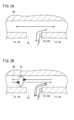
- 2A and 2B are diagrams illustrating a detection unit provided on a motor.
- 3A and 3B are diagrams illustrating a detection unit provided in a motor according to the first modification.
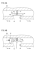
- 4A and 4B are diagrams illustrating a restricting member of a motor according to the second modification.
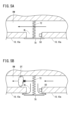
- 5A and 5B are diagrams illustrating a restricting member of a motor according to a third modification.
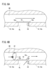
- 6A and 6B are diagrams illustrating a restricting member of a motor according to a fourth modification.
- 7A and 7B are diagrams illustrating a restricting member of a motor according to a fifth modification.
- 8A and 8B are diagrams illustrating a restricting member of a motor according to a sixth modification.
- FIG. 1 is a diagram showing a schematic configuration of a motor 10 according to one embodiment.
- the motor 10 has a rotor (not shown) provided with a rotating shaft 12, a stator 14, and a housing 16.
- a ventilation passage RW is provided inside the motor 10, through which cooling air passes to cool the motor 10.
- the rotating shaft 12 and the rotor rotate about a rotation axis AX.
- the stator 14 covers the rotor in a cylindrical shape.
- the housing 16 is provided on the surface 14a side of the axial direction DA of the stator 14.
- the axial direction DA of the stator 14 is the same direction as the rotation axis AX of the rotating shaft 12.
- the housing 16 has a bracket 18 and a fan cover 20.
- the bracket 18 rotatably supports the rotating shaft 12 by a bearing (not shown).
- the fan cover 20 is attached to the stator 14 via the bracket 18.
- a fan 22 is attached to the fan cover 20.
- the fan 22 has a fan motor and an impeller, both of which are not shown.
- the fan motor drives and rotates the impeller, causing the fan 22 to generate cooling air.
- the generated cooling air passes through the ventilation path RW as described above.
- the ventilation passage RW extends in the axial direction DA of the stator 14 through each of the stator 14 and the housing 16.
- the ventilation passage RW includes a first ventilation passage RW1, a second ventilation passage RW2, and a third ventilation passage RW3.
- the first ventilation passage RW1 is formed in the stator 14.
- the second ventilation passage RW2 is formed in the bracket 18.
- the third ventilation passage RW3 is formed in the fan cover 20.
- the third ventilation passage RW3 may be a space within the fan cover 20.
- the first ventilation passage RW1 communicates with the second ventilation passage RW2.
- the second ventilation passage RW2 communicates with the third ventilation passage RW3.
- the third ventilation passage RW3 communicates with the outside air via the ventilation opening 20a of the fan cover 20.
- the end of the first ventilation passage RW1 opposite the end communicating with the second ventilation passage RW2 communicates with the outside air.
- the cooling air is generated, for example, when the air outside the motor 10 flows into the first ventilation passage RW1 due to the intake of the fan 22. As shown by the dashed arrow Wi in FIG. 1, the cooling air that flows into the first ventilation passage RW1 passes through the second ventilation passage RW2 and the third ventilation passage RW3 in that order, and flows into the outside air from the ventilation opening 20a.
- the cooling air is generated, for example, when the fan 22 blows air from outside the motor 10 and causes it to flow into the third ventilation passage RW3 through the ventilation opening 20a. As shown by the solid arrow Ws in FIG. 1, the cooling air that flows into the third ventilation passage RW3 passes through the second ventilation passage RW2 and the first ventilation passage RW1 in that order, and then flows into the outside air.
- the first ventilation passage RW1 is formed penetrating through the stator 14, it tends to have a smaller cross-sectional area than the third ventilation passage RW3. Therefore, there is a possibility that dust and the like may become clogged, particularly in the first ventilation passage RW1. Furthermore, if the cross-sectional areas of the second ventilation passage RW2 and the third ventilation passage RW3 are small, there is also a possibility that dust and the like may become clogged in the second ventilation passage RW2 and the third ventilation passage RW3. If a blockage occurs in the ventilation passage RW, the cooling performance of the motor 10 will decrease. In this embodiment, if a blockage occurs in the ventilation passage RW, the user is notified of this fact.
- a communication hole HL and a detection unit 50 are provided.
- the communication hole HL is formed on the outer peripheral side surface 10a of the motor 10 centered on the rotation axis AX of the rotating shaft 12.
- the communication hole HL communicates with the ventilation passage RW and also communicates with the air outside the motor 10. Some of the cooling air mentioned above may also flow through the communication hole HL.
- the communication hole HL is provided with a detection unit 50 that detects the volume of cooling air flowing through the communication hole HL.
- the volume of the cooling air flowing through the communication hole HL may fluctuate.
- the detection unit 50 can detect the fluctuation in the volume of the cooling air flowing through the communication hole HL.
- the user can remove the blockage in the ventilation passage RW. Since it is possible to reduce the time that the blockage in the ventilation passage RW continues, the time that the motor 10 is in an overheated state can be shortened. Therefore, the stability of the motor cooling performance can be ensured.
- the communication hole HL may be formed in either the stator 14 or the housing 16.
- the detection unit 50 be able to detect fluctuations in air volume even if a blockage occurs at any point in the first ventilation passage RW1.
- the communication hole HL may be formed in a position on the housing 16 close to the stator 14.
- the stator 14 is more likely to become hot than the housing 16.
- the communication hole HL may be formed in the stator 14. Since the communication hole HL is connected to the first ventilation passage RW1, cooling air passes through at least a part of the first ventilation passage RW1. This reduces the possibility that the overheated motor 10 will stop before the blockage in the ventilation passage RW is cleared.
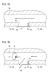
- FIGS. 2A and 2B are diagrams illustrating a detection unit 50 provided on the motor 10.
- An air flow sensor 50A is used as an example of the detection unit 50.
- the air flow sensor 50A transmits a sensor signal indicating the detected air flow or fluctuations in the air flow to an external device (not shown) of the motor 10. Based on the received sensor signal, the external device notifies the user that there may be a blockage in the ventilation passage RW.
- FIG. 2A there is no blockage DT in the ventilation passage RW, so the cooling air can pass through the ventilation passage RW. Some of the cooling air also flows through the communication hole HL.
- FIG. 2B a blockage DT has occurred in the ventilation passage RW, so the flow of the cooling air in the ventilation passage RW is hindered. In that case, a pressure difference may occur between the internal pressure Pi of the ventilation passage RW and the external pressure Po of the motor 10. To eliminate this pressure difference, the amount of cooling air flowing through the communication hole HL increases. Note that to eliminate this pressure difference, the cooling air may also flow through the gaps in the motor 10. In that case, the amount of cooling air flowing through the communication hole HL decreases.
- the air flow sensor 50A transmits a sensor signal to an external device based on the detected air flow or fluctuations in the air flow.
- the user can recognize the possibility that a blockage DT has occurred in the ventilation passage RW of the motor 10 even if the user is located far away from the motor 10. By allowing the user to take measures to remove the blockage DT, the motor cooling performance can be expected to become stable.
- the detection unit 50 is not limited to the airflow sensor 50A.
- Figures 3A and 3B are diagrams illustrating a detection unit 50 provided in the motor 10 according to Modification 1.
- a whistle unit 50B is used as another example of the detection unit 50.
- the whistle portion 50B is provided so as to narrow the diameter of the communication hole HL from the peripheral wall surrounding the communication hole HL of the stator 14 or housing 16 toward the center of the communication hole HL.
- the whistle portion 50B is attached to the peripheral wall of the communication hole HL by an attachment member AT.
- This whistle portion 50B may be provided in a non-detachable manner on the peripheral wall of the communication hole HL, or may be attached detachably. By making the whistle portion 50B detachable, it is possible to attach whistles 50B with different tones or threshold air volume for sound production.
- the whistle 50B produces a sound according to the volume of cooling air flowing through the communication hole HL. Specifically, a sound is produced when the volume of air increases above a predetermined volume, and no sound is produced when the volume of air decreases below the predetermined volume. Therefore, the whistle 50B can alert the user that a blockage has occurred in the ventilation passage RW.
- the whistle 50B starts making a sound that had stopped or stops making a sound that had stopped in response to fluctuations in the air volume.
- a user near the motor 10 can recognize the possibility of a blockage DT in the ventilation passage RW of the motor 10 at an early stage based on the change in sound from the whistle 50B.
- Stable motor cooling performance can be expected as the user can immediately take steps to remove the blockage DT.
- FIGS. 4A and 4B are diagrams illustrating a restricting member of the motor 10 according to the modified example 2. The restricting member restricts the gas flowing through the communication hole HL.
- the restricting member is, for example, a lid 70 that blocks the communication hole HL.
- the lid 70 blocks the communication hole HL at the boundary between the communication hole HL and the ventilation passage RW.
- the motor 10 has a biasing member 72 that biases the lid 70.
- the biasing member 72 is, for example, an elastic body, and is attached to the peripheral wall of the ventilation passage RW and the lid 70.
- the biasing member 72 biases the lid 70 so that the communication hole HL opens.
- the lid 70 opens the communication hole HL according to the pressure difference between the internal pressure Pi of the ventilation passage RW and the external pressure Po of the motor 10. As a result, the lid 70 releases the restriction on the gas flowing through the communication hole HL.
- the lid 70 has a top 70a, a peripheral portion 70b, and an inclined portion 70c.
- the top 70a is located in the center of the lid 70.
- the peripheral portion 70b contacts the peripheral wall of the ventilation passage RW on the outer periphery of the communication hole HL, allowing the lid 70 to block the communication hole HL.
- the inclined portion 70c is located between the top 70a and the peripheral portion 70b. Due to the inclination of the inclined portion 70c, the top 70a protrudes from the peripheral portion 70b into the peripheral wall of the ventilation passage RW.
- the cooling air heading toward the fan 22 can pass through the ventilation passage RW.
- the threshold value Ta is higher than the external pressure Po of the motor 10 (Ta>Po).
- the inclined surface of the inclined portion 70c of the lid 70 facing the ventilation passage RW is pushed by the cooling air, so that the lid 70 blocks the communication hole HL against the biasing force of the biasing member 72. Therefore, gas does not flow through the communication hole HL. This reduces the possibility of dust or the like clogging the communication hole HL.
- FIG. 4B shows an example in which the cooling air flowing from the outside of the stator 14 toward the ventilation opening 20a is blocked by a blockage DT. Because the cooling air is blocked, the internal pressure Pi of the ventilation passage RW drops.
- the lid 70 opens the communication hole HL in accordance with the biasing force of the biasing member 72. The cooling air now flows through the communication hole HL, and the amount of air flow is detected by the detection unit 50.
- the biasing member 72 may bias the lid 70 so that the communication hole HL is blocked.
- the lid 70 opens the communication hole HL according to the pressure difference between the internal pressure Pi of the ventilation passage RW and the external pressure Po of the motor 10. This causes the lid 70 to release the restriction on the gas flowing through the communication hole HL.
- the top 70a of the lid 70 does not need to protrude from the peripheral portion 70b into the peripheral wall of the ventilation passage RW. In other words, the lid 70 does not have an inclined portion 70c.
- the lid 70 blocks the communication hole HL in accordance with the biasing force of the biasing member 72.
- the internal pressure Pi of the ventilation passage RW decreases. Therefore, the lid 70 opens the communication hole HL against the biasing force of the biasing member 72.
- the detection unit 50 can properly detect the volume of cooling air flowing through the communication hole HL when the communication hole HL is opened due to the blockage DT.
- FIGS 5A and 5B are diagrams illustrating a restricting member of the motor 10 according to modification 3.
- the restricting member, lid 70 closes the communication hole HL at the boundary between the communication hole HL and the outer peripheral side surface 10a of the motor 10.
- the motor 10 has a biasing member 72 that biases the lid 70.
- the biasing member 72 biases the lid 70 so that the communication hole HL is blocked.
- the lid 70 opens the communication hole HL according to the pressure difference between the internal pressure Pi of the ventilation passage RW and the external pressure Po of the motor 10. This causes the lid 70 to release the restriction on the gas flowing through the communication hole HL.
- the detection unit 50 can properly detect the volume of cooling air flowing through the communication hole HL when the communication hole HL is opened due to the blockage DT.
- FIGS. 6A and 6B are diagrams illustrating a restricting member of the motor 10 according to modified example 4.
- the cover 70 closes the communication hole HL at the boundary between the communication hole HL and the ventilation passage RW.
- the lid 70 is a biasing member that is biased to open the communication hole HL.
- a portion 70d of the peripheral edge of the lid 70 is fixed to an area of the peripheral wall surrounding the ventilation passage RW that is located on the periphery of the communication hole HL.
- a portion 70e of the peripheral edge of the lid 70 that is not fixed to the peripheral wall surrounding the ventilation passage RW is biased. This opens the communication hole HL.
- the lid 70 opens the communication hole HL in response to the pressure difference between the internal pressure Pi of the ventilation passage RW and the external pressure Po of the motor 10. This causes the lid 70 to release the restriction on the gas flowing through the communication hole HL.
- FIG. 6B shows an example in which the cooling air flowing from the outside of the stator 14 toward the ventilation opening 20a is blocked by a blockage DT. Because the cooling air is blocked, the internal pressure Pi of the ventilation passage RW drops.
- the lid 70 opens the communication hole HL according to the biasing force of the lid 70. New cooling air begins to flow through the communication hole HL, and the amount of air is detected by the detection unit 50.
- the lid 70 may block the communication hole HL according to the biasing force of the lid 70. As shown in FIG. 6A, when there is no blockage DT in the ventilation passage RW, the lid 70 maintains the state of blocking the communication hole HL. As shown in FIG. 6B, when a blockage DT occurs in the ventilation passage RW, the internal pressure Pi of the ventilation passage RW decreases. The lid 70 opens the communication hole HL against the biasing force of the lid 70 according to the pressure difference between the internal pressure Pi of the ventilation passage RW and the external pressure Po of the motor 10. This causes the lid 70 to release the restriction on the gas flowing through the communication hole HL.
- the detection unit 50 can properly detect the volume of cooling air flowing through the communication hole HL when the communication hole HL is opened due to the blockage DT.
- FIGS 7A and 7B are diagrams illustrating a restricting member of the motor 10 according to modified example 5.
- the cover 70 closes the communication hole HL at the boundary between the communication hole HL and the outer peripheral side surface 10a of the motor 10.
- the lid 70 is a biasing member biased to block the communication hole HL.
- a portion 70f of the peripheral edge of the lid 70 is fixed to an area of the outer peripheral side surface 10a of the motor 10 that is located on the periphery of the communication hole HL.
- a portion 70g of the peripheral edge of the lid 70 that is not fixed to the outer peripheral side surface 10a of the motor 10 is biased. This blocks the communication hole HL.
- the lid 70 opens the communication hole HL depending on the pressure difference between the internal pressure Pi of the ventilation passage RW and the external pressure Po of the motor 10. This causes the lid 70 to release the restriction on the gas flowing through the communication hole HL.
- the cover 70 opens the communication hole HL against the biasing force of the cover 70 in accordance with the pressure difference between the internal pressure Pi of the ventilation passage RW and the external pressure Po of the motor 10.
- the cooling air also flows through the communication hole HL, and the amount of air flow is detected by the detection unit 50.
- the detection unit 50 can properly detect the volume of cooling air flowing through the communication hole HL when the communication hole HL is opened due to the blockage DT.
- FIG. 6 In the above-described modified examples 2 to 5, the lid 70, which is a restricting member, closes or opens the communication hole HL against the biasing force.
- the restricting member is not limited to this lid 70.
- Figures 8A and 8B are diagrams illustrating a restricting member of the motor 10 according to modified example 6.
- the lid 70 closes the communication hole HL at the boundary between the communication hole HL and the ventilation passage RW.
- the same is true in the case where the lid 70 closes the communication hole HL at the boundary between the communication hole HL and the outer circumferential side surface 10a of the motor 10.
- the motor 10 has a driving member 80 that drives the lid 70.
- the driving member 80 drives the lid 70, which allows the lid 70 to close or open the communication hole HL.
- the driving member 80 detects the internal pressure Pi of the ventilation passage RW and the external pressure Po of the motor 10 using a pressure sensor (not shown).
- the driving member 80 opens the communication hole HL in response to the pressure difference between the internal pressure Pi of the ventilation passage RW and the external pressure Po of the motor 10. This causes the lid 70 to release the restriction on the gas flowing through the communication hole HL.
- FIG. 8A there is no blockage DT in the ventilation passage RW, so the cooling air can pass through the ventilation passage RW.
- Te is higher than the external pressure Po of the motor 10 (Te>Po).
- the cover 70 blocks the communication hole HL as it is driven by the driving member 80. Therefore, gas does not flow through the communication hole HL. This reduces the possibility of dust or the like clogging the communication hole HL.
- FIG. 8B shows an example in which the cooling air is blocked by the blockage DT. Because the cooling air is blocked, the internal pressure Pi of the ventilation passage RW drops.
- the lid 70 opens the communication hole HL as driven by the driving member 80.
- the cooling air now flows through the communication hole HL, and the amount of air flow is detected by the detection unit 50.
- the detection unit 50 can properly detect the volume of cooling air flowing through the communication hole HL when the communication hole HL is opened due to the blockage DT.
- a plurality of ventilation passages RW may be provided in the motor 10, and a plurality of communication holes HL may be formed in each of the ventilation passages RW.
- the detection unit 50 is provided in each of the plurality of communication holes HL. This makes it easier to identify the location where the blockage DT occurs.
- a detection unit 50 is provided in the communication hole HL. This allows the user to recognize the possibility that a blockage DT has occurred in the ventilation passage RW of the motor 10. By allowing the user to take measures to remove the blockage DT, the stability of the motor cooling performance can be expected.
- the present disclosure relates to a motor (10) comprising a stator (14) and a housing (16) provided on the stator and to which a fan (22) is attached, wherein each of the stator and the housing is provided with an air passage (RW) extending along an axial direction (DA) of the stator and through which cooling air generated by the fan passes, and the stator or the housing is formed with a communication hole (HL) communicating the air passage with the outside of the motor, and the communication hole is provided with a detection unit (50) for detecting the volume of the cooling air flowing through the communication hole.
- RW air passage
- DA axial direction
- HL communication hole
- the housing may be provided on the axial surface (14a) side of the stator, and the communication hole may communicate with the ventilation passage and an outer peripheral side surface (10a) of the motor.
- the motor described in Appendix 1 or 2 may have a regulating member that regulates the gas flowing through the communication hole, and the regulating member may release the regulation of the gas depending on the pressure difference between the internal pressure (Pi) of the ventilation passage and the external pressure (Po) of the motor.
- the regulating member may be a lid (70) that closes the communication hole.
- the motor described in Appendix 4 may further include a biasing member (72) that biases the lid so that the communication hole is open, and when the internal pressure is equal to or greater than a threshold value (Ta) that is higher than the external pressure, the lid may block the communication hole against the biasing force of the biasing member.
- a biasing member (72) that biases the lid so that the communication hole is open, and when the internal pressure is equal to or greater than a threshold value (Ta) that is higher than the external pressure, the lid may block the communication hole against the biasing force of the biasing member.
- the motor described in Appendix 4 may further include a biasing member that biases the lid so that the communication hole is blocked, and when the internal pressure is equal to or greater than a threshold value (Tb) that is higher than the external pressure, the lid may open the communication hole against the biasing force of the biasing member.
- Tb threshold value
- the lid is a biasing member biased to open the communication hole, and when the internal pressure is equal to or greater than a threshold value (Tc) higher than the external pressure, the lid may block the communication hole against the biasing force of the lid.
- Tc threshold value
- the lid is a biasing member biased to block the communication hole, and when the internal pressure is equal to or greater than a threshold value (Td) higher than the external pressure, the lid may open the communication hole against the biasing force of the lid.
- Td threshold value
- the housing has a fan cover (20) that covers the fan and a bracket (18) for attaching the fan cover to the stator, and the communication hole may be formed in the bracket or the fan cover.
- the detection unit may be an air flow sensor (50A).
- the detection unit may be a whistle unit (50B) that produces a sound in accordance with the air volume.
- the whistle portion may be detachable from the communication hole.
Landscapes
- Engineering & Computer Science (AREA)
- Power Engineering (AREA)
- Motor Or Generator Cooling System (AREA)
- Motor Or Generator Frames (AREA)
Abstract
本開示の一態様は、モータであって、ステータと、前記ステータに設けられ、ファンが取り付けられるハウジングとを備え、前記ステータと前記ハウジングとの各々に、前記ステータの軸方向に沿って延び、前記ファンによって発生する冷却風が通る通風路が設けられ、前記ステータまたは前記ハウジングには、前記通風路と前記モータの外部と連通する連通孔が形成され、前記連通孔には、前記連通孔を流れる前記冷却風の風量を検知する検知部が設けられている。
Description
本開示は、モータに関する。
特開2018-85899号公報には、電動機が開示されている。その電動機は、ステータおよびハウジングを冷却する冷却構造を備える。
モータ冷却性能の安定性が望まれている。
本開示の一態様は、モータであって、ステータと、前記ステータに設けられ、ファンが取り付けられるハウジングと、を備え、前記ステータと前記ハウジングとの各々に、前記ステータの軸方向に沿って延び、前記ファンによって発生する冷却風が通る通風路が設けられ、前記ステータまたは前記ハウジングには、前記通風路とモータの外部と連通する連通孔が形成され、前記連通孔には、前記連通孔を流れる前記冷却風の風量を検知する検知部が設けられている。
ファンが取り付けられたモータにおいて、ファンの継続的な使用により、ファンによって発生した冷却風が流れる通風路に塵埃等が詰まる場合がある。その場合、冷却風の流通が阻害され、モータが過熱状態となり得る。モータが過熱状態になると、モータが停止する可能性がある。
(実施形態)
図1は、一実施形態によるモータ10の構成を模式的に示す図である。モータ10は、回転軸12が設けられた不図示のロータと、ステータ14と、ハウジング16とを有する。モータ10の内部には、モータ10を冷却するための冷却風が通る通風路RWが設けられる。回転軸12および前記ロータは、回転軸線AXを中心に回転する。ステータ14は、前記ロータを筒状に覆う。
図1は、一実施形態によるモータ10の構成を模式的に示す図である。モータ10は、回転軸12が設けられた不図示のロータと、ステータ14と、ハウジング16とを有する。モータ10の内部には、モータ10を冷却するための冷却風が通る通風路RWが設けられる。回転軸12および前記ロータは、回転軸線AXを中心に回転する。ステータ14は、前記ロータを筒状に覆う。
ハウジング16は、ステータ14の軸方向DAの面14a側に設けられる。ステータ14の軸方向DAは、回転軸12の回転軸線AXの方向と同じ方向である。ハウジング16は、ブラケット18と、ファンカバー20とを有する。ブラケット18は、不図示のベアリングにより回転軸12を回転可能に支持する。
ファンカバー20は、ブラケット18を介してステータ14に取り付けられる。ファンカバー20には、ファン22が取り付けられる。ファン22は、いずれも不図示のファンモータおよびインペラを有する。前記ファンモータが前記インペラを回転駆動することにより、ファン22は冷却風を発生させる。発生した冷却風は、上述したように通風路RWを通る。
通風路RWは、ステータ14とハウジング16との各々に、ステータ14の軸方向DAに沿って延びる。通風路RWは、第1通風路RW1と、第2通風路RW2と、第3通風路RW3とを含む。第1通風路RW1はステータ14内に形成される。第2通風路RW2は、ブラケット18内に形成される。第3通風路RW3は、ファンカバー20内に形成される。第3通風路RW3は、ファンカバー20内の空間であってもよい。
第1通風路RW1は、第2通風路RW2に連通する。第2通風路RW2は、第3通風路RW3と連通する。第3通風路RW3は、ファンカバー20が有する換気口20aを介して外気に連通する。また、第1通風路RW1のうち、第2通風路RW2と連通する端部の反対側の端部は外気に連通する。
冷却風は、例えば、ファン22の吸気によってモータ10の外気が第1通風路RW1に流入することで発生する。図1の破線矢印Wiに示すように、第1通風路RW1に流入した冷却風は、第2通風路RW2および第3通風路RW3の順に通って、換気口20aから外気に流れる。
冷却風は、例えば、ファン22の送気によってモータ10の外気が換気口20aを介して第3通風路RW3に流入することで発生する。図1の実線矢印Wsに示すように、第3通風路RW3に流入した冷却風は、第2通風路RW2および第1通風路RW1の順に通って、外気に流れる。
第1通風路RW1はステータ14内を貫通して形成されるため、第3通風路RW3より断面積が狭くなる傾向がある。そのため、特に第1通風路RW1には塵埃等が詰まる可能性がある。また、第2通風路RW2および第3通風路RW3の断面積が狭い場合も、第2通風路RW2、第3通風路RW3に塵埃等が詰まる可能性がある。通風路RWに詰まりが生じた場合は、モータ10の冷却性能が低下する。本実施形態では、通風路RWに詰まりが発生した場合に、その旨がユーザへ報知される。
通風路RWの詰まりを検出するために、本実施形態では、連通孔HLと検知部50(図2A、図2B、図3Aおよび図3B参照)とが設けられている。連通孔HLは、回転軸12の回転軸線AXを中心とするモータ10の外周側面10aに形成されている。連通孔HLは、通風路RWと連通し、且つモータ10の外気と連通する。上述した冷却風の一部は、連通孔HLをも流れ得る。連通孔HLには、連通孔HLを流れる冷却風の風量を検知する検知部50が設けられている。
通風路RWに詰まりが生じた場合、連通孔HLを流れる冷却風の風量は変動し得る。検知部50は、連通孔HLを流れる冷却風の風量の変動を検知できる。
検知部50による検知に応じて、ユーザは、通風路RWの詰まりを取り除くことができる。通風路RWの詰まりが継続する時間を抑えることが可能となるため、モータ10が過熱状態となる時間を短くすることができる。したがって、モータ冷却性能の安定性を確保することができる。
連通孔HLは、ステータ14およびハウジング16のいずれに形成されてもよい。例えば、第1通風路RW1のいずれの箇所に詰まりが生じた場合であっても検知部50が風量の変動を検知できるのが好ましい。その場合、連通孔HLは、ハウジング16の、ステータ14に近い位置に形成されてもよい。
また、ハウジング16よりステータ14の方が高熱になりやすい。その場合、連通孔HLは、ステータ14に形成されてもよい。連通孔HLが第1通風路RW1に連通しているため、第1通風路RW1のうちの少なくとも一部を冷却風が通る。通風路RWの詰まりが取り除かれる前に過熱状態のモータ10が停止する可能性を低減することができる。
図2Aおよび図2Bは、モータ10に設けられた検知部50を例示する図である。図2Aおよび図2Bでは、説明の便宜のため、連通孔HLの大きさが拡大されている。それは、以降の図においても同様である。検知部50の一例として、風量センサ50Aが用いられる。風量センサ50Aは、検知した風量または風量の変動を示すセンサ信号を、モータ10の外部装置(不図示)へ送信する。外部装置は、受信したセンサ信号に基づいて、通風路RWに詰まりが生じた可能性があることをユーザへ報知する。
図2Aにおいては、通風路RWに詰まりDTがないため冷却風が通風路RWを通ることができる。冷却風の一部は、連通孔HLをも流れる。図2Bにおいては、通風路RWに詰まりDTが生じたため、通風路RWにおける冷却風の流通が阻害されている。その場合、通風路RWの内圧Piと、モータ10の外圧Poとに差圧が生じ得る。その差圧を解消するため、連通孔HLを流れる冷却風の風量は増大する。なお、その差圧解消のために、冷却風がモータ10の隙間を流通する場合もある。その場合、連通孔HLを流れる冷却風の風量は減少する。
本実施形態によると、風量センサ50Aは、検知した風量または風量の変動に基づいて、センサ信号を外部装置へ送信する。ユーザは、モータ10から離れた位置であっても、モータ10の通風路RWに詰まりDTが生じた可能性を認識することができる。ユーザが詰まりDTを除去する対処が行われることにより、モータ冷却性能の安定性が期待され得る。
上記の実施形態は、下記のように変形してもよい。下記の変形例では、実施形態と重複する説明は割愛する。また、下記の変形例に用いられる図は、実施形態において説明した構成と同一の構成については同一の符号を付す。
(変形例1)
検知部50は風量センサ50Aに限られない。図3Aおよび図3Bは、変形例1によるモータ10に設けられた検知部50を例示する図である。検知部50の他の例として、笛部50Bが用いられる。
検知部50は風量センサ50Aに限られない。図3Aおよび図3Bは、変形例1によるモータ10に設けられた検知部50を例示する図である。検知部50の他の例として、笛部50Bが用いられる。
笛部50Bは、ステータ14またはハウジング16の連通孔HLを囲む周壁から、連通孔HLの中心に向かって、連通孔HLの口径を狭めるように設けられる。笛部50Bは、取り付け部材ATにより、連通孔HLの周壁に取り付けられている。この笛部50Bは、連通孔HLの周壁に着脱不能に設けられていてもよいし、着脱可能に取り付けられてもよい。笛部50Bを着脱可能とすることで、音色または音が鳴る風量の閾値が異なる笛部50Bを取り付けることができる。
笛部50Bにより、連通孔HLを流れる冷却風の風量に応じて音が鳴る。具体的には、風量が所定量より増加すると音が鳴り、風量が所定量より減少すると音が鳴らない。したがって、笛部50Bは、通風路RWに詰まりが生じたことをユーザに報知することができる。
本変形例によると、笛部50Bでは、風量の変動に応じて、止んでいた音が鳴り始めるか、または鳴っていた音が止む。モータ10の付近にいるユーザは、笛部50Bからの音の変化に基づいて、モータ10の通風路RWに詰まりDTが生じた可能性を、早期に認識することができる。ユーザが直ちに詰まりDTを除去する対処が行われることにより、モータ冷却性能の安定性が期待され得る。
(変形例2)
上記の実施形態では、冷却風の一部が、連通孔HLを常時流れている。これにより、連通孔HLが塵埃等によって詰まる可能性がある。そこで、本変形例2では、通風路RWに詰まりDTが生じていない場合、連通孔HLに流れる気体が規制される。図4Aおよび図4Bは、変形例2によるモータ10が有する規制部材を例示する図である。規制部材は、連通孔HLに流れる気体を規制する。
上記の実施形態では、冷却風の一部が、連通孔HLを常時流れている。これにより、連通孔HLが塵埃等によって詰まる可能性がある。そこで、本変形例2では、通風路RWに詰まりDTが生じていない場合、連通孔HLに流れる気体が規制される。図4Aおよび図4Bは、変形例2によるモータ10が有する規制部材を例示する図である。規制部材は、連通孔HLに流れる気体を規制する。
変形例2~変形例6において、規制部材は、例えば、連通孔HLを塞ぐ蓋70である。本変形例では、蓋70は、連通孔HLと通風路RWとの境界で連通孔HLを塞ぐ。モータ10は、蓋70を付勢する付勢部材72を有する。
付勢部材72は、例えば弾性体であり、通風路RWの周壁と蓋70とに取り付けられている。付勢部材72は、連通孔HLが開くように蓋70を付勢する。蓋70は、通風路RWの内圧Piとモータ10の外圧Poとの差圧に応じて、連通孔HLを開ける。これにより、蓋70は、連通孔HLに流れる気体に対する規制を解除する。
蓋70は、頂部70aと周縁部70bと傾斜部70cとを有する。頂部70aは蓋70の中央に位置する。周縁部70bが連通孔HLの外周において通風路RWの周壁と接することにより、蓋70は連通孔HLを塞ぐことができる。傾斜部70cは、頂部70aと周縁部70bとの間に位置する。傾斜部70cの傾きにより、頂部70aは、周縁部70bから通風路RWの周壁内に突出している。
上述した吸気の場合、図4Aにおいては、通風路RWに詰まりDTがないため、ファン22へ向かう冷却風は通風路RWを通ることができる。通風路RWの内圧Piは、閾値Ta以上である(Pi>=Ta)。なお、閾値Taは、モータ10の外圧Poより高い(Ta>Po)。その場合、蓋70の傾斜部70cの通風路RWに向いている傾斜面が冷却風により押されるため、蓋70は、付勢部材72の付勢力に抗して連通孔HLを塞ぐ。したがって、連通孔HLを気体が流れない。これにより、連通孔HLに塵埃等が詰まる可能性を低減することができる。
通風路RWに詰まりDTが生じた場合、上述したように、通風路RWの内圧Piと、モータ10の外圧Poとに差圧が生じ得る。図4Bは、ステータ14の外部から換気口20aへ向かう冷却風が、詰まりDTにより阻害された例を示している。冷却風が阻害されたため、通風路RWの内圧Piが低下する。蓋70は、付勢部材72の付勢力にしたがって、連通孔HLを開ける。冷却風が連通孔HLをも流れるようになり、その風量が検知部50により検知される。
なお、付勢部材72は、連通孔HLが塞がれるように蓋70を付勢してもよい。蓋70は、通風路RWの内圧Piとモータ10の外圧Poとの差圧に応じて、連通孔HLを開ける。これにより、蓋70は、連通孔HLに流れる気体に対する規制を解除する。その場合、蓋70の頂部70aは、周縁部70bから通風路RWの周壁内に突出しなくてよい。すなわち、蓋70は、傾斜部70cを有しない。
図4Aに示すように通風路RWに詰まりDTがない状態では、蓋70は、付勢部材72の付勢力にしたがって、連通孔HLを塞ぐ。図4Bに示すように通風路RWに詰まりDTが生じた場合、通風路RWの内圧Piが低下する。したがって、蓋70は、付勢部材72の付勢力に抗して連通孔HLを開ける。
本変形例によると、通風路RWに詰まりDTがない場合、連通孔HLを気体が流れない。連通孔HLに塵埃等が詰まる可能性が低減される。したがって、検知部50は、詰まりDTにより連通孔HLが開いた場合に連通孔HLを流れる冷却風の風量を、適切に検知できる。
(変形例3)
上記の変形例2では、通風路RW内の詰まりDTにより、通風路RWの内圧Piが低下する。しかし、通風路RW内の詰まりDTにより、通風路RWの内圧Piが上昇する場合がある。図5Aおよび図5Bは、変形例3によるモータ10が有する規制部材を例示する図である。本変形例において、規制部材である蓋70は、連通孔HLとモータ10の外周側面10aとの境界で連通孔HLを塞ぐ。
上記の変形例2では、通風路RW内の詰まりDTにより、通風路RWの内圧Piが低下する。しかし、通風路RW内の詰まりDTにより、通風路RWの内圧Piが上昇する場合がある。図5Aおよび図5Bは、変形例3によるモータ10が有する規制部材を例示する図である。本変形例において、規制部材である蓋70は、連通孔HLとモータ10の外周側面10aとの境界で連通孔HLを塞ぐ。
モータ10は、蓋70を付勢する付勢部材72を有する。付勢部材72は、連通孔HLが塞がれるように蓋70を付勢する。蓋70は、通風路RWの内圧Piとモータ10の外圧Poとの差圧に応じて、連通孔HLを開ける。これにより、蓋70は、連通孔HLに流れる気体に対する規制を解除する。
上述した送気の場合、図5Aにおいては、通風路RWに詰まりDTがないため、ファン22からの冷却風は通風路RWを通ることができる。蓋70は、付勢部材72の付勢力にしたがって、連通孔HLを塞ぐ。したがって、連通孔HLを気体が流れない。これにより、連通孔HLに塵埃等が詰まる可能性を低減することができる。
通風路RWに詰まりDTが生じた場合、上述したように、通風路RWの内圧Piと、モータ10の外圧Poとに差圧が生じ得る。図5Bは、換気口20aからステータ14の外部へ向かう冷却風が、詰まりDTにより阻害された例を示している。冷却風が阻害されたため、通風路RWの内圧Piが上昇する。通風路RWの内圧Piは、閾値Tb以上になる(Pi>=Tb)。なお、閾値Tbは、モータ10の外圧Poより高い(Tb>Po)。その場合、蓋70は、付勢部材72の付勢力に抗して連通孔HLを開ける。冷却風が連通孔HLをも流れるようになり、その風量が検知部50により検知される。
本変形例によると、通風路RWに詰まりDTがない場合、連通孔HLを気体が流れない。連通孔HLに塵埃等が詰まる可能性が低減される。したがって、検知部50は、詰まりDTにより連通孔HLが開いた場合に連通孔HLを流れる冷却風の風量を、適切に検知できる。
(変形例4)
上記の変形例2では、付勢部材72が蓋70を付勢する。しかし、蓋70自体が付勢部材であってもよい。図6Aおよび図6Bは、変形例4によるモータ10が有する規制部材を例示する図である。本変形例では、蓋70は、連通孔HLと通風路RWとの境界で連通孔HLを塞ぐ。
上記の変形例2では、付勢部材72が蓋70を付勢する。しかし、蓋70自体が付勢部材であってもよい。図6Aおよび図6Bは、変形例4によるモータ10が有する規制部材を例示する図である。本変形例では、蓋70は、連通孔HLと通風路RWとの境界で連通孔HLを塞ぐ。
蓋70は、連通孔HLが開くように付勢された付勢部材である。蓋70の周縁部の一部70dが、通風路RWを囲む周壁のうち、連通孔HLの周縁に位置する領域に固定されている。蓋70の周縁部のうち、通風路RWを囲む周壁に固定されていない部分70eが付勢される。これにより、連通孔HLが開く。蓋70は、通風路RWの内圧Piとモータ10の外圧Poとの差圧に応じて、連通孔HLを開ける。これにより、蓋70は、連通孔HLに流れる気体に対する規制を解除する。
上述した吸気の場合、図6Aにおいては、通風路RWに詰まりDTがないため、ファン22へ向かう冷却風は通風路RWを通ることができる。通風路RWの内圧Piは、閾値Tc以上である(Pi>=Tc)。なお、閾値Tcは、モータ10の外圧Poより高い(Tc>Po)。その場合、蓋70の付勢された部分70eの通風路RWに向いている傾斜面が冷却風により押されるため、蓋70は、蓋70が有する付勢力に抗して連通孔HLを塞ぐ。したがって、連通孔HLを気体が流れない。これにより、連通孔HLに塵埃等が詰まる可能性を低減することができる。
通風路RWに詰まりDTが生じた場合、上述したように、通風路RWの内圧Piと、モータ10の外圧Poとに差圧が生じ得る。図6Bは、ステータ14の外部から換気口20aへ向かう冷却風が詰まりDTにより阻害された例を示している。冷却風が阻害されたため、通風路RWの内圧Piが低下する。蓋70は、蓋70が有する付勢力にしたがって、連通孔HLを開ける。新たに冷却風が連通孔HLを流れるようになり、その風量が検知部50により検知される。
なお、蓋70は、蓋70が有する付勢力にしたがって連通孔HLを塞いでもよい。図6Aに示すように通風路RWに詰まりDTがない状態では、蓋70が連通孔HLを塞いだ状態が維持される。図6Bに示すように通風路RWに詰まりDTが生じた場合、通風路RWの内圧Piが低下する。蓋70は、通風路RWの内圧Piとモータ10の外圧Poとの差圧に応じて、蓋70の付勢力に抗して連通孔HLを開ける。これにより、蓋70は、連通孔HLに流れる気体に対する規制を解除する。
本変形例によると、通風路RWに詰まりDTがない場合、連通孔HLを気体が流れない。連通孔HLに塵埃等が詰まる可能性が低減される。したがって、検知部50は、詰まりDTにより連通孔HLが開いた場合に連通孔HLを流れる冷却風の風量を、適切に検知できる。
(変形例5)
上記の変形例3では、付勢部材72が蓋70を付勢する。しかし、蓋70自体が付勢部材であってもよい。図7Aおよび図7Bは、変形例5によるモータ10が有する規制部材を例示する図である。本変形例では、蓋70は、連通孔HLとモータ10の外周側面10aとの境界で連通孔HLを塞ぐ。
上記の変形例3では、付勢部材72が蓋70を付勢する。しかし、蓋70自体が付勢部材であってもよい。図7Aおよび図7Bは、変形例5によるモータ10が有する規制部材を例示する図である。本変形例では、蓋70は、連通孔HLとモータ10の外周側面10aとの境界で連通孔HLを塞ぐ。
蓋70は、連通孔HLが塞がれるように付勢された付勢部材である。蓋70の周縁部の一部70fが、モータ10の外周側面10aのうち、連通孔HLの周縁に位置する領域に固定されている。蓋70の周縁部のうち、モータ10の外周側面10aに固定されていない部分70gが付勢される。これにより、連通孔HLが塞がれる。蓋70は、通風路RWの内圧Piとモータ10の外圧Poとの差圧に応じて、連通孔HLを開ける。これにより、蓋70は、連通孔HLに流れる気体に対する規制を解除する。
上述した送気の場合、図7Aにおいては、通風路RWに詰まりDTがないため、ファン22からの冷却風は通風路RWを通ることができる。蓋70は、蓋70が有する付勢力にしたがって、連通孔HLを塞ぐ。したがって、連通孔HLを気体が流れない。これにより、連通孔HLに塵埃等が詰まる可能性を低減することができる。
通風路RWに詰まりDTが生じた場合、上述したように、通風路RWの内圧Piと、モータ10の外圧Poとに差圧が生じ得る。図7Bは、換気口20aからステータ14の外部へ向かう冷却風が、詰まりDTにより阻害された例を示している。冷却風が阻害されたため、通風路RWの内圧Piが上昇する。通風路RWの内圧Piは、閾値Td以上になる(Pi>=Td)。なお、閾値Tdは、モータ10の外圧Poより高い(Td>Po)。その場合、蓋70は、通風路RWの内圧Piとモータ10の外圧Poとの差圧に応じて、蓋70が有する付勢力に抗して連通孔HLを開ける。冷却風が連通孔HLをも流れるようになり、その風量が検知部50により検知される。
本変形例によると、通風路RWに詰まりDTがない場合、連通孔HLを気体が流れない。連通孔HLに塵埃等が詰まる可能性が低減される。したがって、検知部50は、詰まりDTにより連通孔HLが開いた場合に連通孔HLを流れる冷却風の風量を、適切に検知できる。
(変形例6)
上記の変形例2~5において、規制部材である蓋70は、付勢力に抗して連通孔HLを塞ぐか、または開ける。しかし、規制部材はこうした蓋70に限られない。図8Aおよび図8Bは、変形例6によるモータ10が有する規制部材を例示する図である。本変形例では、蓋70は、連通孔HLと通風路RWとの境界で連通孔HLを塞ぐ。しかし、蓋70が、連通孔HLとモータ10の外周側面10aとの境界で連通孔HLを塞ぐ場合においても、同様である。
上記の変形例2~5において、規制部材である蓋70は、付勢力に抗して連通孔HLを塞ぐか、または開ける。しかし、規制部材はこうした蓋70に限られない。図8Aおよび図8Bは、変形例6によるモータ10が有する規制部材を例示する図である。本変形例では、蓋70は、連通孔HLと通風路RWとの境界で連通孔HLを塞ぐ。しかし、蓋70が、連通孔HLとモータ10の外周側面10aとの境界で連通孔HLを塞ぐ場合においても、同様である。
モータ10は、蓋70を駆動する駆動部材80を有する。駆動部材80が蓋70を駆動することにより、蓋70は連通孔HLを塞ぐことも開けることもできる。駆動部材80は、不図示の圧力センサを用いて、通風路RWの内圧Piおよびモータ10の外圧Poを検出する。通風路RWの内圧Piとモータ10の外圧Poとの差圧に応じて、駆動部材80は連通孔HLを開く。これにより、蓋70は、連通孔HLに流れる気体に対する規制を解除する。
図8Aにおいては、通風路RWに詰まりDTがないため、冷却風は通風路RWを通ることができる。通風路RWの内圧Piは、閾値Te以上である(Pi>=Te)。なお、閾値Teは、モータ10の外圧Poより高い(Te>Po)。その場合、蓋70は、駆動部材80による駆動にしたがって、連通孔HLを塞ぐ。したがって、連通孔HLを気体が流れない。これにより、連通孔HLに塵埃等が詰まる可能性を低減することができる。
通風路RWに詰まりDTが生じた場合、上述したように、通風路RWの内圧Piと、モータ10の外圧Poとに差圧が生じ得る。図8Bは、詰まりDTにより冷却風が阻害された例を示している。冷却風が阻害されたため、通風路RWの内圧Piが低下する。蓋70は、駆動部材80による駆動にしたがって、連通孔HLを開ける。冷却風が連通孔HLをも流れるようになり、その風量が検知部50により検知される。
本変形例によると、通風路RWに詰まりDTがない場合、連通孔HLを気体が流れない。連通孔HLに塵埃等が詰まる可能性が低減される。したがって、検知部50は、詰まりDTにより連通孔HLが開いた場合に連通孔HLを流れる冷却風の風量を、適切に検知できる。
(変形例7)
モータ10に複数の通風路RWが設けられ、各通風路RWに複数の連通孔HLが形成されてもよい。その場合、複数の連通孔HLの各々に、検知部50が設けられる。これにより、詰まりDTの発生位置を特定しやすくなる。
モータ10に複数の通風路RWが設けられ、各通風路RWに複数の連通孔HLが形成されてもよい。その場合、複数の連通孔HLの各々に、検知部50が設けられる。これにより、詰まりDTの発生位置を特定しやすくなる。
(変形例8)
上記変形例1~7は、矛盾しない範囲内において適宜組み合わされてもよい。
上記変形例1~7は、矛盾しない範囲内において適宜組み合わされてもよい。
上記実施形態および変形例において、連通孔HLに検知部50が設けられる。これにより、ユーザは、モータ10の通風路RWに詰まりDTが生じた可能性を認識することができる。ユーザが詰まりDTを除去する対処が行われることにより、モータ冷却性能の安定性が期待され得る。
上記実施形態および変形例に関し、さらに以下の付記を開示する。
(付記1)
本開示は、モータ(10)であって、ステータ(14)と、前記ステータに設けられ、ファン(22)が取り付けられるハウジング(16)と、を備え、前記ステータと前記ハウジングとの各々に、前記ステータの軸方向(DA)に沿って延び、前記ファンによって発生する冷却風が通る通風路(RW)が設けられ、前記ステータまたは前記ハウジングには、前記通風路とモータの外部と連通する連通孔(HL)が形成され、前記連通孔には、前記連通孔を流れる前記冷却風の風量を検知する検知部(50)が設けられている。
本開示は、モータ(10)であって、ステータ(14)と、前記ステータに設けられ、ファン(22)が取り付けられるハウジング(16)と、を備え、前記ステータと前記ハウジングとの各々に、前記ステータの軸方向(DA)に沿って延び、前記ファンによって発生する冷却風が通る通風路(RW)が設けられ、前記ステータまたは前記ハウジングには、前記通風路とモータの外部と連通する連通孔(HL)が形成され、前記連通孔には、前記連通孔を流れる前記冷却風の風量を検知する検知部(50)が設けられている。
(付記2)
付記1に記載のモータであって、前記ハウジングは、前記ステータの前記軸方向の面(14a)側に設けられ、前記連通孔は、前記通風路と前記モータの外周側面(10a)と連通してもよい。
付記1に記載のモータであって、前記ハウジングは、前記ステータの前記軸方向の面(14a)側に設けられ、前記連通孔は、前記通風路と前記モータの外周側面(10a)と連通してもよい。
(付記3)
付記1または2に記載のモータであって、前記連通孔に流れる気体を規制する規制部材を有し、前記規制部材は、前記通風路の内圧(Pi)と前記モータの外圧(Po)との差圧に応じて前記気体に対する規制を解除してもよい。
付記1または2に記載のモータであって、前記連通孔に流れる気体を規制する規制部材を有し、前記規制部材は、前記通風路の内圧(Pi)と前記モータの外圧(Po)との差圧に応じて前記気体に対する規制を解除してもよい。
(付記4)
付記3に記載のモータであって、前記規制部材は、前記連通孔を塞ぐ蓋(70)であってもよい。
付記3に記載のモータであって、前記規制部材は、前記連通孔を塞ぐ蓋(70)であってもよい。
(付記5)
付記4に記載のモータであって、前記連通孔が開くように前記蓋を付勢する付勢部材(72)をさらに備え、前記内圧が、前記外圧よりも高い閾値(Ta)以上の場合、前記蓋は前記付勢部材の付勢力に抗して前記連通孔を塞いでもよい。
付記4に記載のモータであって、前記連通孔が開くように前記蓋を付勢する付勢部材(72)をさらに備え、前記内圧が、前記外圧よりも高い閾値(Ta)以上の場合、前記蓋は前記付勢部材の付勢力に抗して前記連通孔を塞いでもよい。
(付記6)
付記4に記載のモータであって、前記連通孔が塞がれるように前記蓋を付勢する付勢部材をさらに備え、前記内圧が、前記外圧よりも高い閾値(Tb)以上の場合、前記蓋は前記付勢部材の付勢力に抗して前記連通孔を開けてもよい。
付記4に記載のモータであって、前記連通孔が塞がれるように前記蓋を付勢する付勢部材をさらに備え、前記内圧が、前記外圧よりも高い閾値(Tb)以上の場合、前記蓋は前記付勢部材の付勢力に抗して前記連通孔を開けてもよい。
(付記7)
付記4に記載のモータであって、前記蓋は、前記連通孔が開くように付勢された付勢部材であり、前記内圧が、前記外圧よりも高い閾値(Tc)以上の場合、前記蓋は前記蓋の付勢力に抗して前記連通孔を塞いでもよい。
付記4に記載のモータであって、前記蓋は、前記連通孔が開くように付勢された付勢部材であり、前記内圧が、前記外圧よりも高い閾値(Tc)以上の場合、前記蓋は前記蓋の付勢力に抗して前記連通孔を塞いでもよい。
(付記8)
付記4に記載のモータであって、前記蓋は、前記連通孔が塞がれるように付勢された付勢部材であり、前記内圧が、前記外圧よりも高い閾値(Td)以上の場合、前記蓋は前記蓋の付勢力に抗して前記連通孔を開けてもよい。
付記4に記載のモータであって、前記蓋は、前記連通孔が塞がれるように付勢された付勢部材であり、前記内圧が、前記外圧よりも高い閾値(Td)以上の場合、前記蓋は前記蓋の付勢力に抗して前記連通孔を開けてもよい。
(付記9)
付記1~8のいずれかに記載のモータであって、前記ハウジングは、前記ファンを覆うファンカバー(20)と、前記ファンカバーを前記ステータに取り付けるためのブラケット(18)とを有し、前記連通孔は、前記ブラケットまたは前記ファンカバーに形成されていてもよい。
付記1~8のいずれかに記載のモータであって、前記ハウジングは、前記ファンを覆うファンカバー(20)と、前記ファンカバーを前記ステータに取り付けるためのブラケット(18)とを有し、前記連通孔は、前記ブラケットまたは前記ファンカバーに形成されていてもよい。
(付記10)
付記1~9のいずれかに記載のモータであって、前記検知部は、風量センサ(50A)であってもよい。
付記1~9のいずれかに記載のモータであって、前記検知部は、風量センサ(50A)であってもよい。
(付記11)
付記1~9のいずれかに記載のモータであって、前記検知部は、前記風量に応じて音が鳴る笛部(50B)であってもよい。
付記1~9のいずれかに記載のモータであって、前記検知部は、前記風量に応じて音が鳴る笛部(50B)であってもよい。
(付記12)
付記11に記載のモータであって、前記笛部は、前記連通孔に対して着脱可能であってもよい。
付記11に記載のモータであって、前記笛部は、前記連通孔に対して着脱可能であってもよい。
本開示について詳述したが、本開示は上述した個々の実施形態に限定されるものではない。これらの実施形態は、本開示の要旨を逸脱しない範囲で、または、請求の範囲に記載された内容とその均等物から導き出される本開示の趣旨を逸脱しない範囲で、種々の追加、置き換え、変更、部分的削除等が可能である。また、これらの実施形態は、組み合わせて実施することもできる。例えば、上述した実施形態において、各動作の順序や各処理の順序は、一例として示したものであり、これらに限定されるものではない。また、上述した実施形態の説明に数値または数式が用いられている場合も同様である。
10…モータ 12…回転軸
14…ステータ 16…ハウジング
18…ブラケット 20…ファンカバー
22…ファン 50…検知部
70…蓋 72…付勢部材
80…駆動部材
14…ステータ 16…ハウジング
18…ブラケット 20…ファンカバー
22…ファン 50…検知部
70…蓋 72…付勢部材
80…駆動部材
Claims (12)
- ステータと、
前記ステータに設けられ、ファンが取り付けられるハウジングと、
を備え、
前記ステータと前記ハウジングとの各々に、前記ステータの軸方向に沿って延び、前記ファンによって発生する冷却風が通る通風路が設けられ、
前記ステータまたは前記ハウジングには、前記通風路とモータの外部と連通する連通孔が形成され、
前記連通孔には、前記連通孔を流れる前記冷却風の風量を検知する検知部が設けられている、モータ。 - 請求項1に記載のモータであって、
前記ハウジングは、前記ステータの前記軸方向の面側に設けられ、
前記連通孔は、前記通風路と前記モータの外周側面と連通する、モータ。 - 請求項1または2に記載のモータであって、
前記連通孔に流れる気体を規制する規制部材を有し、
前記規制部材は、前記通風路の内圧と前記モータの外圧との差圧に応じて前記気体に対する規制を解除する、モータ。 - 請求項3に記載のモータであって、
前記規制部材は、前記連通孔を塞ぐ蓋である、モータ。 - 請求項4に記載のモータであって、
前記連通孔が開くように前記蓋を付勢する付勢部材をさらに備え、
前記内圧が、前記外圧よりも高い閾値以上の場合、前記蓋は前記付勢部材の付勢力に抗して前記連通孔を塞ぐ、モータ。 - 請求項4に記載のモータであって、
前記連通孔が塞がれるように前記蓋を付勢する付勢部材をさらに備え、
前記内圧が、前記外圧よりも高い閾値以上の場合、前記蓋は前記付勢部材の付勢力に抗して前記連通孔を開ける、モータ。 - 請求項4に記載のモータであって、
前記蓋は、前記連通孔が開くように付勢された付勢部材であり、
前記内圧が、前記外圧よりも高い閾値以上の場合、前記蓋は前記蓋の付勢力に抗して前記連通孔を塞ぐ、モータ。 - 請求項4に記載のモータであって、
前記蓋は、前記連通孔が塞がれるように付勢された付勢部材であり、
前記内圧が、前記外圧よりも高い閾値以上の場合、前記蓋は前記蓋の付勢力に抗して前記連通孔を開ける、モータ。 - 請求項1~8のいずれか1項に記載のモータであって、
前記ハウジングは、前記ファンを覆うファンカバーと、前記ファンカバーを前記ステータに取り付けるためのブラケットとを有し、
前記連通孔は、前記ブラケットまたは前記ファンカバーに形成されている、モータ。 - 請求項1~9のいずれか1項に記載のモータであって、
前記検知部は、風量センサである、モータ。 - 請求項1~9のいずれか1項に記載のモータであって、
前記検知部は、前記風量に応じて音が鳴る笛部である、モータ。 - 請求項11に記載のモータであって、
前記笛部は、前記連通孔に対して着脱可能である、モータ。
Priority Applications (3)
| Application Number | Priority Date | Filing Date | Title |
|---|---|---|---|
| PCT/JP2023/003700 WO2024166149A1 (ja) | 2023-02-06 | 2023-02-06 | モータ |
| JP2024575862A JPWO2024166149A1 (ja) | 2023-02-06 | 2023-02-06 | |
| TW113104118A TW202433834A (zh) | 2023-02-06 | 2024-02-02 | 馬達 |
Applications Claiming Priority (1)
| Application Number | Priority Date | Filing Date | Title |
|---|---|---|---|
| PCT/JP2023/003700 WO2024166149A1 (ja) | 2023-02-06 | 2023-02-06 | モータ |
Publications (1)
| Publication Number | Publication Date |
|---|---|
| WO2024166149A1 true WO2024166149A1 (ja) | 2024-08-15 |
Family
ID=92262651
Family Applications (1)
| Application Number | Title | Priority Date | Filing Date |
|---|---|---|---|
| PCT/JP2023/003700 Ceased WO2024166149A1 (ja) | 2023-02-06 | 2023-02-06 | モータ |
Country Status (3)
| Country | Link |
|---|---|
| JP (1) | JPWO2024166149A1 (ja) |
| TW (1) | TW202433834A (ja) |
| WO (1) | WO2024166149A1 (ja) |
Citations (7)
| Publication number | Priority date | Publication date | Assignee | Title |
|---|---|---|---|---|
| JPS5496707A (en) * | 1978-01-17 | 1979-07-31 | Hitachi Ltd | Alternating current generator for automobile |
| JPS61129466U (ja) * | 1985-01-30 | 1986-08-13 | ||
| JPH119526A (ja) * | 1997-06-24 | 1999-01-19 | Tec Corp | 電気掃除機 |
| JP2002238216A (ja) * | 2001-02-07 | 2002-08-23 | Kawasaki Steel Corp | 空冷式モータ過負荷保護装置および方法 |
| JP2007201174A (ja) * | 2006-01-26 | 2007-08-09 | Nec Computertechno Ltd | 電子機器用冷却装置及びフィルター目詰まり検出方法 |
| JP2010172179A (ja) * | 2008-12-24 | 2010-08-05 | Toshiba Corp | 車両駆動装置 |
| JP2021090254A (ja) * | 2019-12-03 | 2021-06-10 | ファナック株式会社 | 電動機 |
-
2023
- 2023-02-06 WO PCT/JP2023/003700 patent/WO2024166149A1/ja not_active Ceased
- 2023-02-06 JP JP2024575862A patent/JPWO2024166149A1/ja active Pending
-
2024
- 2024-02-02 TW TW113104118A patent/TW202433834A/zh unknown
Patent Citations (7)
| Publication number | Priority date | Publication date | Assignee | Title |
|---|---|---|---|---|
| JPS5496707A (en) * | 1978-01-17 | 1979-07-31 | Hitachi Ltd | Alternating current generator for automobile |
| JPS61129466U (ja) * | 1985-01-30 | 1986-08-13 | ||
| JPH119526A (ja) * | 1997-06-24 | 1999-01-19 | Tec Corp | 電気掃除機 |
| JP2002238216A (ja) * | 2001-02-07 | 2002-08-23 | Kawasaki Steel Corp | 空冷式モータ過負荷保護装置および方法 |
| JP2007201174A (ja) * | 2006-01-26 | 2007-08-09 | Nec Computertechno Ltd | 電子機器用冷却装置及びフィルター目詰まり検出方法 |
| JP2010172179A (ja) * | 2008-12-24 | 2010-08-05 | Toshiba Corp | 車両駆動装置 |
| JP2021090254A (ja) * | 2019-12-03 | 2021-06-10 | ファナック株式会社 | 電動機 |
Also Published As
| Publication number | Publication date |
|---|---|
| TW202433834A (zh) | 2024-08-16 |
| JPWO2024166149A1 (ja) | 2024-08-15 |
Similar Documents
| Publication | Publication Date | Title |
|---|---|---|
| JP5314256B2 (ja) | 回転流体機械のシール装置および回転流体機械 | |
| EP1707822B1 (en) | Centrifugal fan | |
| CN101169120B (zh) | 风机单元 | |
| US20070231130A1 (en) | Centrifugal fan | |
| JP2602773Y2 (ja) | 内燃機関用水ポンプ | |
| GB2238852A (en) | Viscous coupling | |
| JP7353742B2 (ja) | 流体機械 | |
| WO2024166149A1 (ja) | モータ | |
| JP4441978B2 (ja) | 送風装置 | |
| JP5217626B2 (ja) | 車両用空調装置のブロワユニット | |
| JP4542479B2 (ja) | モーターの強制熱放散構造 | |
| JP2010520396A (ja) | スパイラルケーシングを有する渦巻きポンプ | |
| JP2008232024A (ja) | 送風機および空調機 | |
| KR20030031841A (ko) | 하드디스크 조립체 | |
| JP2802289B2 (ja) | 温度感応型流体式ファン・カップリング装置 | |
| JPH09215271A (ja) | 可変速モータの冷却装置 | |
| JP2000179490A (ja) | 軸流ファン | |
| JP4862809B2 (ja) | 遠心式送風機 | |
| JPS63270518A (ja) | フイルタ目詰検出器 | |
| JPH07208390A (ja) | 電動送風機 | |
| CN217904169U (zh) | 马达、具备该马达的送风装置及具备该送风装置的吸尘器 | |
| EP4563826A1 (en) | Impeller, blower, and air conditioner | |
| JP2008057385A (ja) | 送風機および送風機を備えた冷却機器 | |
| JP2002115697A (ja) | 電動送風機 | |
| JP4941855B2 (ja) | 電動送風機 |
Legal Events
| Date | Code | Title | Description |
|---|---|---|---|
| 121 | Ep: the epo has been informed by wipo that ep was designated in this application |
Ref document number: 23920987 Country of ref document: EP Kind code of ref document: A1 |
|
| WWE | Wipo information: entry into national phase |
Ref document number: 2024575862 Country of ref document: JP |
|
| NENP | Non-entry into the national phase |
Ref country code: DE |
|
| 122 | Ep: pct application non-entry in european phase |
Ref document number: 23920987 Country of ref document: EP Kind code of ref document: A1 |