WO2024162147A1 - ガラス基板及び光集積デバイス - Google Patents
ガラス基板及び光集積デバイス Download PDFInfo
- Publication number
- WO2024162147A1 WO2024162147A1 PCT/JP2024/002112 JP2024002112W WO2024162147A1 WO 2024162147 A1 WO2024162147 A1 WO 2024162147A1 JP 2024002112 W JP2024002112 W JP 2024002112W WO 2024162147 A1 WO2024162147 A1 WO 2024162147A1
- Authority
- WO
- WIPO (PCT)
- Prior art keywords
- glass
- less
- glass substrate
- refractive index
- core
- Prior art date
- Legal status (The legal status is an assumption and is not a legal conclusion. Google has not performed a legal analysis and makes no representation as to the accuracy of the status listed.)
- Ceased
Links
Images



Classifications
-
- G—PHYSICS
- G02—OPTICS
- G02B—OPTICAL ELEMENTS, SYSTEMS OR APPARATUS
- G02B6/00—Light guides; Structural details of arrangements comprising light guides and other optical elements, e.g. couplings
- G02B6/10—Light guides; Structural details of arrangements comprising light guides and other optical elements, e.g. couplings of the optical waveguide type
- G02B6/12—Light guides; Structural details of arrangements comprising light guides and other optical elements, e.g. couplings of the optical waveguide type of the integrated circuit kind
- G02B6/122—Basic optical elements, e.g. light-guiding paths
- G02B6/1223—Basic optical elements, e.g. light-guiding paths high refractive index type, i.e. high-contrast waveguides
-
- C—CHEMISTRY; METALLURGY
- C03—GLASS; MINERAL OR SLAG WOOL
- C03C—CHEMICAL COMPOSITION OF GLASSES, GLAZES OR VITREOUS ENAMELS; SURFACE TREATMENT OF GLASS; SURFACE TREATMENT OF FIBRES OR FILAMENTS MADE FROM GLASS, MINERALS OR SLAGS; JOINING GLASS TO GLASS OR OTHER MATERIALS
- C03C13/00—Fibre or filament compositions
- C03C13/04—Fibre optics, e.g. core and clad fibre compositions
- C03C13/045—Silica-containing oxide glass compositions
-
- C—CHEMISTRY; METALLURGY
- C03—GLASS; MINERAL OR SLAG WOOL
- C03C—CHEMICAL COMPOSITION OF GLASSES, GLAZES OR VITREOUS ENAMELS; SURFACE TREATMENT OF GLASS; SURFACE TREATMENT OF FIBRES OR FILAMENTS MADE FROM GLASS, MINERALS OR SLAGS; JOINING GLASS TO GLASS OR OTHER MATERIALS
- C03C21/00—Treatment of glass, not in the form of fibres or filaments, by diffusing ions or metals in the surface
- C03C21/001—Treatment of glass, not in the form of fibres or filaments, by diffusing ions or metals in the surface in liquid phase, e.g. molten salts, solutions
- C03C21/005—Treatment of glass, not in the form of fibres or filaments, by diffusing ions or metals in the surface in liquid phase, e.g. molten salts, solutions to introduce in the glass such metals or metallic ions as Ag, Cu
-
- C—CHEMISTRY; METALLURGY
- C03—GLASS; MINERAL OR SLAG WOOL
- C03C—CHEMICAL COMPOSITION OF GLASSES, GLAZES OR VITREOUS ENAMELS; SURFACE TREATMENT OF GLASS; SURFACE TREATMENT OF FIBRES OR FILAMENTS MADE FROM GLASS, MINERALS OR SLAGS; JOINING GLASS TO GLASS OR OTHER MATERIALS
- C03C3/00—Glass compositions
- C03C3/04—Glass compositions containing silica
- C03C3/076—Glass compositions containing silica with 40% to 90% silica, by weight
- C03C3/078—Glass compositions containing silica with 40% to 90% silica, by weight containing an oxide of a divalent metal, e.g. an oxide of zinc
-
- C—CHEMISTRY; METALLURGY
- C03—GLASS; MINERAL OR SLAG WOOL
- C03C—CHEMICAL COMPOSITION OF GLASSES, GLAZES OR VITREOUS ENAMELS; SURFACE TREATMENT OF GLASS; SURFACE TREATMENT OF FIBRES OR FILAMENTS MADE FROM GLASS, MINERALS OR SLAGS; JOINING GLASS TO GLASS OR OTHER MATERIALS
- C03C3/00—Glass compositions
- C03C3/04—Glass compositions containing silica
- C03C3/076—Glass compositions containing silica with 40% to 90% silica, by weight
- C03C3/083—Glass compositions containing silica with 40% to 90% silica, by weight containing aluminium oxide or an iron compound
- C03C3/085—Glass compositions containing silica with 40% to 90% silica, by weight containing aluminium oxide or an iron compound containing an oxide of a divalent metal
-
- C—CHEMISTRY; METALLURGY
- C03—GLASS; MINERAL OR SLAG WOOL
- C03C—CHEMICAL COMPOSITION OF GLASSES, GLAZES OR VITREOUS ENAMELS; SURFACE TREATMENT OF GLASS; SURFACE TREATMENT OF FIBRES OR FILAMENTS MADE FROM GLASS, MINERALS OR SLAGS; JOINING GLASS TO GLASS OR OTHER MATERIALS
- C03C3/00—Glass compositions
- C03C3/04—Glass compositions containing silica
- C03C3/076—Glass compositions containing silica with 40% to 90% silica, by weight
- C03C3/083—Glass compositions containing silica with 40% to 90% silica, by weight containing aluminium oxide or an iron compound
- C03C3/085—Glass compositions containing silica with 40% to 90% silica, by weight containing aluminium oxide or an iron compound containing an oxide of a divalent metal
- C03C3/087—Glass compositions containing silica with 40% to 90% silica, by weight containing aluminium oxide or an iron compound containing an oxide of a divalent metal containing calcium oxide, e.g. common sheet or container glass
-
- C—CHEMISTRY; METALLURGY
- C03—GLASS; MINERAL OR SLAG WOOL
- C03C—CHEMICAL COMPOSITION OF GLASSES, GLAZES OR VITREOUS ENAMELS; SURFACE TREATMENT OF GLASS; SURFACE TREATMENT OF FIBRES OR FILAMENTS MADE FROM GLASS, MINERALS OR SLAGS; JOINING GLASS TO GLASS OR OTHER MATERIALS
- C03C3/00—Glass compositions
- C03C3/04—Glass compositions containing silica
- C03C3/076—Glass compositions containing silica with 40% to 90% silica, by weight
- C03C3/089—Glass compositions containing silica with 40% to 90% silica, by weight containing boron
- C03C3/091—Glass compositions containing silica with 40% to 90% silica, by weight containing boron containing aluminium
-
- G—PHYSICS
- G02—OPTICS
- G02B—OPTICAL ELEMENTS, SYSTEMS OR APPARATUS
- G02B6/00—Light guides; Structural details of arrangements comprising light guides and other optical elements, e.g. couplings
- G02B6/10—Light guides; Structural details of arrangements comprising light guides and other optical elements, e.g. couplings of the optical waveguide type
- G02B6/12—Light guides; Structural details of arrangements comprising light guides and other optical elements, e.g. couplings of the optical waveguide type of the integrated circuit kind
- G02B2006/12035—Materials
- G02B2006/12038—Glass (SiO2 based materials)
-
- G—PHYSICS
- G02—OPTICS
- G02B—OPTICAL ELEMENTS, SYSTEMS OR APPARATUS
- G02B6/00—Light guides; Structural details of arrangements comprising light guides and other optical elements, e.g. couplings
- G02B6/10—Light guides; Structural details of arrangements comprising light guides and other optical elements, e.g. couplings of the optical waveguide type
- G02B6/12—Light guides; Structural details of arrangements comprising light guides and other optical elements, e.g. couplings of the optical waveguide type of the integrated circuit kind
- G02B6/13—Integrated optical circuits characterised by the manufacturing method
- G02B6/134—Integrated optical circuits characterised by the manufacturing method by substitution by dopant atoms
- G02B6/1345—Integrated optical circuits characterised by the manufacturing method by substitution by dopant atoms using ion exchange
Definitions
- the present invention relates to a glass substrate and an optical integrated device using the glass substrate.
- Optoelectronics convergence technology requires substrates that can transmit both electricity and light.
- Various materials are being considered for such substrates, including Si-Ge substrates in which SiO2 is doped with Ge, Si nanowire substrates in which Si is surrounded by SiO2 , and polymer substrates in which different types of polymers are bonded together.
- Patent Document 1 discloses that glass can be made into an optical waveguide by ion-exchanging Na ions in the glass with Ag ions.
- Patent Document 2 The technology of exchanging ions in glass with other ions is known primarily as a technique for increasing the strength of glass, as shown in Patent Document 2, for example.
- the inventors have conducted research and found that even if an optical waveguide is formed using the above-mentioned conventional ion exchange technology, it is difficult to obtain a stable optical waveguide that achieves control of the core thickness and high uniformity. It is particularly difficult to form an optical waveguide that can handle light propagated in a single mode.
- the present invention aims to provide a glass substrate having an optical waveguide that can also accommodate single-mode propagated light.
- the inventors found that with conventional ion exchange technology for increasing the strength of glass, the ion exchange rate is so fast that it is difficult to control the thickness of the core that serves as the optical waveguide and achieve high uniformity. As a result, they discovered a method for slowing down the ion exchange rate to an appropriate rate, obtained a glass substrate that could solve the above problems, and completed the present invention.
- the refractive index difference expressed by (Nmax-N) is ⁇ n, the maximum value Nmax of the refractive index in the core portion and the refractive index N of the cladding portion are used, then
- the core portion is a region having a refractive index equal to or greater than a value represented by ⁇ N+( ⁇ n/2) ⁇ ,
- the refractive index difference ⁇ n is 0.005 or more
- the glass of the cladding portion has a content, expressed as a mole percentage based on oxides, of: SiO 2 45-80%, Al 2 O 3 0-15%, B 2 O 3 0-20%, A total of 10 to 30% of MgO, CaO, SrO, and BaO; and Na 2 O 4.5-25%
- the glass of the core portion has a content, expressed as a mole percentage based on oxides, of: SiO 2 45-80%, Al 2 O 3 0-15%, B 2 O 3 0-20%, MgO, CaO, SrO and BaO in total 10 to 30%, Na 2 O 0-20%, and
- the glass substrate according to the above [1] which satisfies Ag 2 O content of 0.01% or more.
- the glass substrate according to the present invention has an optical waveguide that can also accommodate single-mode propagated light. Therefore, it is also suitable as a glass substrate having an optical waveguide for introducing single-mode propagated light into a photonics substrate in an optical integrated device.
- FIG. 1 is a schematic diagram for explaining a core portion and a cladding portion in a glass substrate.
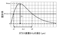
- FIG. 2 is a diagram for explaining the maximum refractive index Nmax, the refractive index N, the refractive index difference ⁇ n, and the core thickness ⁇ d.
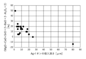
- FIG. 3 is a graph showing the relationship between the value represented by (MgO+CaO+SrO ⁇ 2+BaO ⁇ 2 ⁇ Al 2 O 3 ⁇ 2) in the glass composition of the cladding portion of a glass substrate and the penetration depth of Ag ions when ion exchange treatment is performed.
- FIG. 1 is a schematic diagram for explaining a core portion and a cladding portion in a glass substrate.
- FIG. 2 is a diagram for explaining the maximum refractive index Nmax, the refractive index N, the refractive index difference ⁇ n, and the core thickness ⁇ d.
- FIG. 3 is a graph showing the relationship between the value represented by (MgO+CaO+SrO ⁇
- FIG. 4 is a graph showing the relationship between the value represented by (MgO+CaO ⁇ 2+SrO ⁇ 3+BaO ⁇ 4 ⁇ Al 2 O 3 ⁇ 2) in the glass composition of the cladding portion of a glass substrate and the penetration depth of Ag ions when ion exchange treatment is performed.
- FIG. 5 is a graph showing the relationship between the value represented by ⁇ Na 2 O/(MgO+CaO ⁇ 2+SrO ⁇ 3+BaO ⁇ 4) ⁇ in the glass composition of the cladding portion of a glass substrate and the penetration depth of Ag ions when an ion exchange process is performed.
- FIG. 5 is a graph showing the relationship between the value represented by ⁇ Na 2 O/(MgO+CaO ⁇ 2+SrO ⁇ 3+BaO ⁇ 4) ⁇ in the glass composition of the cladding portion of a glass substrate and the penetration depth of Ag ions when an ion exchange process is performed.
- FIG. 6 is a graph showing the relationship between the value expressed by ⁇ Na 2 O/(MgO+CaO ⁇ 2+SrO ⁇ 3+BaO ⁇ 4 ⁇ Al 2 O 3 ) ⁇ in the glass composition of the cladding portion of a glass substrate and the penetration depth of Ag ions when ion exchange treatment is performed.
- the glass substrate according to this embodiment has a core portion that serves as an optical waveguide, and a clad portion, both of which are made of glass.
- the core has a higher Ag concentration than the cladding, and there is an Ag concentration gradient from the boundary between the core and cladding toward the region of the core where the Ag concentration is maximum. If the refractive index difference expressed by (Nmax-N) is ⁇ n, where Nmax is the maximum value of the refractive index in the core portion and N is the refractive index of the cladding portion, then the core portion is a region where the refractive index is equal to or greater than the value expressed by ⁇ N+( ⁇ n/2) ⁇ . The refractive index difference ⁇ n is 0.005 or more.
- the core thickness ⁇ d of the core portion in the thickness direction of the glass substrate is 2.5 to 10 ⁇ m.
- the core portion that serves as the optical waveguide is formed by ion-exchanging Na ions in the desired region of the glass substrate with Ag ions. Therefore, the composition of the glass in the portion of the cladding that is not affected by ion exchange is the same as the base composition of the glass substrate.
- the portion that is not affected by ion exchange is a portion that is sufficiently far from the core portion; for example, if it is 50 ⁇ m or more away from the boundary between the core portion and the cladding portion, it can be said that there is no influence of ion exchange.
- the composition of the glass that serves as the core portion, with respect to components that are not involved in ion exchange is the same as the base composition of the glass substrate.
- the refractive index of the core is higher than that of the cladding, and it functions as an optical waveguide.
- the Ag concentration in the core is not uniform, but there is an Ag concentration gradient from the boundary between the core and clad to the area of the core where the Ag concentration is maximum. In other words, the Ag concentration changes continuously from the clad to the center of the core. However, this does not mean that there is no tolerance for the Ag concentration remaining unchanged near the center of the core.
- the core is preferably substantially circular in a cross-sectional view perpendicular to the path of the optical waveguide.
- substantially circular we mean a shape with an aspect ratio of 0.33 to 1.25 calculated from the maximum horizontal width and maximum vertical height in the cross-sectional view.
- the aspect ratio is preferably 0.4 or more, more preferably 0.6 or more, and is preferably 1.2 or less, more preferably 1.0 or less. Note that an aspect ratio of 1 is a perfect circle.
- the core may be in a sector shape including a semicircle in the cross-sectional view, and preferably in a semicircle shape.
- the sector shape is formed by two radii and an arc between them, and it is preferable that the arc portion is located vertically downward in the cross-sectional view.
- the Ag concentration is high in the area close to the intersection of the two radii, and decreases with increasing distance from the intersection.
- a low refractive index layer is separately provided on top of the core, so that the core functions as an optical waveguide.
- the low refractive index layer is not particularly limited, and the low refractive index layer functions as the cladding.
- Conventional methods for forming the core section include, for example, forming a film of a component with a high refractive index on part of the substrate surface by sputtering or the like, and then forming another film of a component with a low refractive index, such as the same component as the substrate. Another method is to join different materials with different refractive indices.
- the concentration of the component exhibiting a high refractive index at the boundary between the core and clad portions and the concentration of the component exhibiting a high refractive index in the core portion will change discontinuously.
- the manner in which the concentration of Ag, a component exhibiting a high refractive index from the clad portion to the core portion in this embodiment, changes can be clearly distinguished from the manner in which the concentration of a component exhibiting a high refractive index from the clad portion to the core portion in the conventional clad portion and core portion changes.
- the core portion is formed by ion exchange, so the Ag concentration in the core portion is not constant, and there are differences in the refractive index.
- the area of the cladding portion close to the boundary with the core portion does not have a constant Ag concentration, and there are differences in the refractive index.
- the core portion is defined as follows.
- Fig. 1 is a schematic diagram for explaining the core portion and the cladding portion.
- Fig. 2 is a diagram for explaining the maximum refractive index Nmax, the refractive index N, the refractive index difference ⁇ n, and the core thickness ⁇ d, and is a graph showing the relationship between the depth from the glass substrate surface and the refractive index for a region including the core portion of the glass substrate.
- Fig. 1 nor Fig. 2 relates to an actually obtained glass substrate.
- the refractive index refers to the refractive index of light with a wavelength of 589 nm.
- the maximum value of the refractive index is defined as Nmax in a cross-sectional view perpendicular to the path of the optical waveguide of the core portion 1 in the glass substrate 10 as shown in Fig. 1.
- the refractive index is shown diagrammatically by shades of color, with a darker color indicating a higher refractive index and a lighter color indicating a lower refractive index.
- the relationship between the depth from the surface layer of the glass substrate 10 and the refractive index at each depth is as shown in the graph of Fig. 2.
- the highest refractive index measured in the depth direction from the surface of the glass substrate 10 may be taken as the maximum value Nmax of the refractive index in the core portion 1.
- the refractive index of the cladding portion 2 is set to N.
- the refractive index N of the cladding portion 2 is the refractive index of glass having the same composition as the matrix composition of the glass before ion exchange, i.e., the matrix glass. Note that, in the cladding portion 2 of the glass substrate 10 according to this embodiment, if the refractive index of the cladding portion 1 in a region sufficiently far from the core portion 1 is the same as the refractive index of the matrix composition. Therefore, although it varies depending on the thickness of the glass substrate 10, for example, the refractive index of the glass at the center of the plate thickness of the glass substrate 10 may be set to the refractive index N of the cladding portion 2.
- the refractive index difference expressed by the difference between Nmax and N (Nmax-N) as described above is ⁇ n, and the region where the refractive index is equal to or greater than the value expressed by ⁇ N+( ⁇ n/2) ⁇ , i.e., the region surrounded by the dotted line in Figure 1, is defined as core portion 1.
- the maximum depth in the thickness direction of the core portion 1 at which the refractive index is equal to or greater than ⁇ N+( ⁇ n/2) ⁇ is defined as the core thickness ⁇ d of the core portion 1 in the thickness direction of the glass substrate 10 .
- the refractive index difference ⁇ n between the refractive index N of the cladding portion and the maximum refractive index Nma of the core portion is 0.005 or more, and the core thickness ⁇ d at which the refractive index is equal to or greater than ⁇ N+( ⁇ n/2) ⁇ is 2.5 to 10 ⁇ m, making it possible to create an optical waveguide that can also accommodate light propagated in a single mode.
- ⁇ n may be 0.005 or more, but ⁇ n is preferably 0.005 to 0.05, more preferably 0.007 to 0.04, and may be 0.009 to 0.03, 0.01 to 0.02, or 0.012 to 0.018. From the viewpoint of controlling the bending of the incident light, ⁇ n is 0.005 or more, preferably 0.007 or more, and may be 0.009 or more, 0.01 or more, or 0.012 or more. There is no particular upper limit to ⁇ n, but the refractive index difference that can be generated by ion exchange is usually 0.05 or less, preferably 0.04 or less, and may be 0.03 or less, 0.02 or less, or 0.018 or less.
- the core thickness ⁇ d in the thickness direction of the glass substrate of the core portion is 2.5 to 10 ⁇ m, preferably 3 to 9 ⁇ m, and may be 3.5 to 8 ⁇ m, 4 to 7 ⁇ m, 4.25 to 6 ⁇ m, or 4.5 to 5.5 ⁇ m. It may also be 3 to 8 ⁇ m, 3 to 7 ⁇ m, 3 to 6 ⁇ m, or 3 to 5.5 ⁇ m.
- the smaller the core thickness the greater the refractive index difference between the core portion and the cladding portion must be, but then even a slight change in the refractive index changes the mode field diameter, making it difficult to strictly control the core thickness. Also, if there is a curved region as an optical waveguide, it is difficult to confine the light.
- ⁇ d is set to 2.5 ⁇ m or more, preferably 3 ⁇ m or more, and may be 3.5 ⁇ m or more, 4 ⁇ m or more, 4.25 ⁇ m or more, or 4.5 ⁇ m or more. Furthermore, if the optical waveguide path has a curved region, from the viewpoint of suppressing bending loss, ⁇ d is set to 10 ⁇ m or less, preferably 9 ⁇ m or less, and may be 8 ⁇ m or less, 7 ⁇ m or less, 6 ⁇ m or less, or 5.5 ⁇ m or less.
- Nmax of the refractive index in the core portion is not particularly limited, but in consideration of the refractive index of the matrix composition of the glass substrate normally used in the optical waveguide, Nmax is, for example, preferably 1.50 to 2.0, more preferably 1.51 to 1.9, even more preferably 1.52 to 1.8, even more preferably 1.525 to 1.7, and particularly preferably 1.53 to 1.6.
- Nmax is preferably 1.50 or more, more preferably 1.51 or more, even more preferably 1.52 or more, even more preferably 1.525 or more, and particularly preferably 1.53 or more.
- Nmax is preferably 2.0 or less, more preferably 1.9 or less, even more preferably 1.8 or less, even more preferably 1.7 or less, and particularly preferably 1.6 or less.
- the refractive index N in the cladding portion is not particularly limited, but in consideration of the refractive index of the base composition of a glass substrate normally used in an optical waveguide, N is, for example, preferably 1.50 to 1.59, more preferably 1.51 to 1.58, even more preferably 1.52 to 1.57, even more preferably 1.525 to 1.56, and particularly preferably 1.53 to 1.555.
- N is preferably 1.50 or more, more preferably 1.51 or more, even more preferably 1.52 or more, even more preferably 1.525 or more, and particularly preferably 1.53 or more.
- N is preferably 1.59 or less, more preferably 1.58 or less, even more preferably 1.57 or less, even more preferably 1.56 or less, and particularly preferably 1.555 or less.
- the base composition of the glass substrate according to this embodiment i.e., the composition of the glass in the cladding portion, is not particularly limited as long as the Na ions in the glass are appropriately ion-exchanged with Ag ions to form a core portion with the desired conditions.
- the desired conditions for the core are, for example, ⁇ n of 0.005 or more and ⁇ d of 2.5 to 10 ⁇ m, as described above.
- ⁇ n of 0.005 or more and ⁇ d of 2.5 to 10 ⁇ m, as described above.
- ⁇ d of 2.5 to 10 ⁇ m
- the glass contains a sufficient amount of Na.
- the inventors have found that if the ion exchange that has been conventionally performed to improve glass strength is used to form a core portion, the ion exchange rate is too fast, making it difficult to control the ion exchange depth. As a result, the core thickness ⁇ d exceeds 10 ⁇ m, making it difficult to handle light propagated in a single mode.
- the time that the glass is in contact with the molten salt must also be short, but this results in uneven heating of the glass and reduced homogeneity of the core portion.
- the ion exchange rate is such that a core thickness ⁇ d of 2.5 to 10 ⁇ m can be achieved with an ion exchange process lasting for 20 minutes or more, the ion exchange depth can be appropriately controlled and the homogeneity of the core portion can be maintained.
- the ion exchange process time is preferably 6 hours or less.
- the base composition of the glass substrate according to this embodiment i.e., the glass of the cladding portion
- the content of Al 2 O 3 is preferably 0 to 15%
- the total content of MgO, CaO, SrO and BaO is preferably 10 to 30%, expressed in mole percentage based on oxides.
- the glass of the cladding portion in this embodiment preferably has a content expressed in mole percentage based on oxide of 45-80% SiO 2 and 0-15% Al 2 O 3 . It is also preferable that the glass contains 45-80% SiO 2 and 10-30% MgO, CaO, SrO and BaO in total, and more preferably 45-80% SiO 2 , 0-15% Al 2 O 3 and 10-30% MgO, CaO, SrO and BaO in total. In the above, it is even more preferable that the glass contains 4.5-25% Na 2 O .
- the glass of the cladding portion in this embodiment satisfies the following content, expressed as a mole percentage based on oxides: SiO 2 45-80%, Al 2 O 3 0-15%, B 2 O 3 0-20%, A total of 10 to 30% of MgO, CaO, SrO, and BaO; and Na 2 O 4.5-25%.
- the content of SiO 2 is preferably 40 to 80%, more preferably 45 to 80%, even more preferably 45 to 75%, even more preferably 50 to 70%, even more preferably 52.5 to 67.5%, and particularly preferably 55 to 65%.
- the content of SiO 2 is preferably 40% or more, more preferably 45% or more, even more preferably 50% or more, even more preferably 52.5% or more, and particularly preferably 55% or more.
- the content of SiO 2 is preferably 80% or less, more preferably 75% or less, even more preferably 70% or less, even more preferably 67.5% or less, and particularly preferably 65% or less.
- the content of Al 2 O 3 is preferably 0 to 15%, more preferably 1 to 12.5%, even more preferably 1.5 to 10%, even more preferably 2 to 8%, and particularly preferably 2.5 to 7.5%.
- the content of Al 2 O 3 is preferably 1% or more, more preferably 1.5% or more, even more preferably 2% or more, and even more preferably 2.5% or more.
- the content of Al 2 O 3 is preferably 15% or less, more preferably 12.5% or less, even more preferably 10% or less, even more preferably 8% or less, and particularly preferably 7.5% or less.
- the content of B 2 O 3 is preferably 0 to 20%, more preferably 2 to 17.5%, even more preferably 4 to 15%, even more preferably 6 to 12.5%, and particularly preferably 8 to 11%.
- the content of B 2 O 3 is preferably 2% or more, more preferably 4% or more, even more preferably 6% or more, and even more preferably 8% or more.
- the content of B 2 O 3 is preferably 20% or less, more preferably 17.5% or less, even more preferably 15% or less, even more preferably 12.5% or less, and particularly preferably 11% or less. In order to increase acid resistance, it is preferable not to contain B 2 O 3 .
- the total content of alkaline earth metal oxides represented by the sum of MgO, CaO, SrO and BaO is preferably 10 to 30%, more preferably 11 to 27.5%, even more preferably 12 to 25%, even more preferably 13 to 22.5%, and particularly preferably 14 to 20%.
- the total content is preferably 10% or more, more preferably 11% or more, even more preferably 12% or more, even more preferably 13% or more, and particularly preferably 14% or more.
- the total content is preferably 30% or less, more preferably 27.5% or less, even more preferably 25% or less, even more preferably 22.5% or less, and particularly preferably 20% or less.
- the MgO content is preferably 0-20%, more preferably 1-18%, even more preferably 2-16%, even more preferably 3-14%, and particularly preferably 4-12%.
- MgO is not necessary, but from the viewpoint of improving the meltability of the glass and controlling the ion exchange rate, the MgO content is preferably 1% or more, more preferably 2% or more, even more preferably 3% or more, and particularly preferably 4% or more.
- the MgO content is preferably 20% or less, more preferably 18% or less, even more preferably 16% or less, even more preferably 14% or less, and particularly preferably 12% or less.
- the CaO content is preferably 0-20%, more preferably 1-18%, even more preferably 2-16%, even more preferably 3-14%, even more preferably 4-12%, and particularly preferably 4.5-12%.
- CaO is not necessary, but from the viewpoint of improving the meltability of the glass and controlling the ion exchange rate, the CaO content is preferably 1% or more, more preferably 2% or more, even more preferably 3% or more, even more preferably 4% or more, and particularly preferably 4.5% or more.
- the CaO content is preferably 20% or less, more preferably 18% or less, even more preferably 16% or less, even more preferably 14% or less, and particularly preferably 12% or less.
- the SrO content is preferably 0-20%, more preferably 1-18%, even more preferably 2-16%, even more preferably 3-14%, even more preferably 4-12%, and particularly preferably 4.5-12%.
- SrO is not necessary, but from the viewpoint of improving the meltability of the glass and controlling the ion exchange rate, the SrO content is preferably 1% or more, more preferably 2% or more, even more preferably 3% or more, even more preferably 4% or more, and particularly preferably 4.5% or more.
- the SrO content is preferably 20% or less, more preferably 18% or less, even more preferably 16% or less, even more preferably 14% or less, and particularly preferably 12% or less.
- the BaO content is preferably 0-20%, more preferably 1-18%, even more preferably 2-16%, even more preferably 3-14%, even more preferably 4-12%, and particularly preferably 4.5-12%.
- BaO is not necessary, but from the viewpoint of improving the meltability of the glass and controlling the ion exchange rate, the BaO content is preferably 1% or more, more preferably 2% or more, even more preferably 3% or more, even more preferably 4% or more, and particularly preferably 4.5% or more.
- the BaO content is preferably 20% or less, more preferably 18% or less, even more preferably 16% or less, even more preferably 14% or less, and particularly preferably 12% or less.
- the content of Al 2 O 3 and the total content of alkaline earth metal oxides represented by the total of MgO, CaO, SrO and BaO are both components that reduce the ion exchange rate from Na ions to Ag ions in the glass.
- the penetration depth of Ag ions in FIG. 3 was the depth from the glass surface where the refractive index coincides with the refractive index of the glass before ion exchange treatment when the refractive index distribution from the glass surface was measured using an optical waveguide surface stress meter manufactured by Orihara Seisakusho.
- the value represented by formula (1) is preferably 0 to 30%, more preferably 2.5 to 27.5%, even more preferably 5 to 25%, even more preferably 7.5 to 22.5%, and particularly preferably 10 to 20%.
- the value represented by formula (1) is preferably 0% or more, more preferably 2.5% or more, even more preferably 5% or more, even more preferably 7.5% or more, and particularly preferably 10% or more.
- the value represented by formula (1) is preferably 30% or less, more preferably 27.5% or less, even more preferably 25% or less, even more preferably 22.5% or less, and particularly preferably 20% or less.
- one of the above relational expressions is the expression (2) expressed by (MgO+CaO ⁇ 2+SrO ⁇ 3+BaO ⁇ 4 ⁇ Al 2 O 3 ⁇ 2) using the contents expressed in mole percentage based on oxides.
- 4 shows the relationship between the value represented by formula (2) (MgO+CaO ⁇ 2+SrO ⁇ 3+BaO ⁇ 4 ⁇ Al 2 O 3 ⁇ 2) in the glass composition of the cladding portion of an actually obtained glass substrate and the penetration depth of Ag ions when ion exchange treatment was performed.
- the ion exchange treatment and the method for measuring the penetration depth of Ag ions were the same as those used in the study of formula (1) above.
- the value represented by formula (2) is preferably 0 to 60%, more preferably 5 to 55%, even more preferably 10 to 50%, even more preferably 15 to 45%, and particularly preferably 20 to 40%.
- the value represented by formula (2) is preferably 0% or more, more preferably 5% or more, even more preferably 10% or more, even more preferably 15% or more, and particularly preferably 20% or more.
- the value represented by formula (2) is preferably 60% or less, more preferably 55% or less, even more preferably 50% or less, even more preferably 45% or less, and particularly preferably 40% or less.
- the content of Na 2 O is preferably 4.5 to 25%, more preferably 6 to 22.5%, even more preferably 7 to 20%, even more preferably 8 to 17.5%, and particularly preferably 9 to 16%.
- Na 2 O is a component that imparts a high refractive index so that the core part becomes an optical waveguide by ion exchange with Ag ions, and also improves the melting property of the glass. From the above viewpoint, the content of Na 2 O is preferably 4.5% or more, more preferably 6% or more, even more preferably 7% or more, even more preferably 8% or more, and particularly preferably 9% or more.
- the content of Na 2 O is preferably 25% or less, more preferably 22.5% or less, even more preferably 20% or less, even more preferably 17.5% or less, and particularly preferably 16% or less.
- the content of Na2O and the total content of alkaline earth metal oxides represented by the sum of MgO, CaO, SrO and BaO also have a good correlation with the ion exchange rate.
- formula (3) represented by ⁇ Na 2 O/(MgO+CaO ⁇ 2+SrO ⁇ 3+BaO ⁇ 4) ⁇ using the content expressed in mole percentage based on oxides.
- 5 shows the relationship between the value of the glass composition of the cladding portion of the actually obtained glass substrate, expressed by formula (3); ⁇ Na2O /(MgO+CaOx2+SrOx3+BaOx4) ⁇ , and the penetration depth of Ag ions when ion exchange treatment is performed.
- the ion exchange treatment and the method for measuring the penetration depth of Ag ions are the same as those used in the study of formula (1) above.
- the value represented by formula (3) is preferably 0.1 to 0.7, more preferably 0.125 to 0.6, even more preferably 0.15 to 0.5, even more preferably 0.175 to 0.45, and particularly preferably 0.2 to 0.4.
- the value represented by formula (3) is preferably 0.1 or more, more preferably 0.125 or more, even more preferably 0.15 or more, even more preferably 0.175 or more, and particularly preferably 0.2 or more.
- the value represented by formula (3) is preferably 0.7 or less, more preferably 0.6 or less, even more preferably 0.5 or less, even more preferably 0.45 or less, and particularly preferably 0.4 or less.
- the Al 2 O 3 content also has a good correlation with the ion exchange rate.
- the value represented by formula (4) is preferably 0.1 to 2, more preferably 0.125 to 1.5, even more preferably 0.15 to 1, even more preferably 0.175 to 0.8, and particularly preferably 0.2 to 0.5.
- the value represented by formula (4) is preferably 0.1 or more, more preferably 0.125 or more, even more preferably 0.15 or more, even more preferably 0.175 or more, and particularly preferably 0.2 or more.
- the value represented by formula (4) is preferably 2 or less, more preferably 1.5 or less, even more preferably 1 or less, even more preferably 0.8 or less, and particularly preferably 0.5 or less.
- the content of Li 2 O is preferably 0 to 10%, more preferably 0.1 to 5%, even more preferably 0.3 to 4%, even more preferably 0.4 to 3%, and particularly preferably 0.5 to 2.5%.
- Li 2 O may not be contained, but from the viewpoint of improving the melting property, the content of Li 2 O is preferably 0.1% or more, more preferably 0.3% or more, even more preferably 0.4% or more, and particularly preferably 0.5% or more.
- the content of Li 2 O is preferably 10% or less, more preferably 5% or less, even more preferably 4% or less, even more preferably 3% or less, and particularly preferably 2.5% or less.
- the content of K 2 O is preferably 0 to 10%, more preferably 0.1 to 5%, even more preferably 0.3 to 4%, even more preferably 0.4 to 3%, and particularly preferably 0.5 to 2.5%.
- K 2 O may not be contained, but from the viewpoint of improving the melting property, the content of K 2 O is preferably 0.1% or more, more preferably 0.3% or more, even more preferably 0.4% or more, and even more preferably 0.5% or more.
- the content of K 2 O is preferably 10% or less, more preferably 5% or less, even more preferably 4% or less, even more preferably 3% or less, and particularly preferably 2.5% or less.
- the content of P 2 O 5 is preferably 0 to 4%, more preferably 0.5 to 3%, and even more preferably 1 to 2%.
- P 2 O 5 may not be contained, but from the viewpoint of ion exchange performance and chipping resistance, the content of P 2 O 5 is preferably 0.5% or more, more preferably 1% or more, and even more preferably 2% or more.
- the content of P 2 O 5 is preferably 4% or less, more preferably 3% or less, even more preferably 2% or less, and even more preferably 1% or less. From the viewpoint of acid resistance, it is preferable that P 2 O 5 is not substantially contained.
- the term "substantially free” means that the glass composition contains no impurities other than those contained in the raw materials, i.e., that the glass composition does not contain the impurities intentionally. Specifically, the content of the impurities in the glass composition is less than 0.1 mol%.
- the ZnO content is preferably 0-10%, more preferably 0.25-7%, even more preferably 0.25-5%, even more preferably 0.5-2%, and particularly preferably 0.5-1%.
- ZnO is not necessary, but from the viewpoint of meltability, the ZnO content is preferably 0.25% or more, and more preferably 0.5% or more.
- the ZnO content is preferably 10% or less, more preferably 7% or less, even more preferably 5% or less, even more preferably 2% or less, and particularly preferably 1% or less.
- the content of TiO2 is preferably 0 to 1%, more preferably 0.1 to 0.5%, even more preferably 0.15 to 0.5%, and even more preferably 0.2 to 0.25%.
- TiO2 may not be contained, but from the viewpoint of crushability, the content of TiO2 is preferably 0.1% or more, more preferably 0.15% or more, and even more preferably 0.2% or more.
- the content of TiO2 is preferably 1% or less, more preferably 0.5% or less, and even more preferably 0.25% or less.
- the content of ZrO2 is preferably 0 to 8%, more preferably 0.5 to 6%, even more preferably 0.5 to 4%, even more preferably 1 to 2%, and particularly preferably 1 to 1.2%.
- ZrO2 may not be contained, but from the viewpoint of improving weather resistance, the content of ZrO2 is preferably 0.5% or more, and more preferably 1% or more.
- the content of ZrO2 is preferably 8% or less, more preferably 6% or less, even more preferably 4% or less, even more preferably 2% or less, and particularly preferably 1.2% or less.
- the contents of Y 2 O 3 , La 2 O 3 , and Nb 2 O 5 are each preferably 0 to 8%, more preferably 0.5 to 6%, even more preferably 1 to 5%, even more preferably 1.5 to 4%, even more preferably 2 to 3%, and particularly preferably 2.5 to 3%.
- Y 2 O 3 , La 2 O 3 , and Nb 2 O 5 may not be included, but from the viewpoint of improving weather resistance, the contents of Y 2 O 3 , La 2 O 3 , and Nb 2 O 5 are each preferably 0.5% or more, more preferably 1% or more, even more preferably 1.5% or more, even more preferably 2% or more, and particularly preferably 2.5% or more.
- the content of each of Y 2 O 3 , La 2 O 3 , and Nb 2 O 5 is preferably 8% or less, more preferably 6% or less, even more preferably 5% or less, even more preferably 4% or less, and particularly preferably 3% or less.
- the contents of Ta 2 O 5 and Gd 2 O 3 are each preferably 0 to 1%, and more preferably 0 to 0.5%.
- Ta 2 O 5 and Gd 2 O 3 may not be contained, but may be contained in small amounts from the viewpoint of improving weather resistance.
- the contents of Ta 2 O 5 and Gd 2 O 3 are each preferably 1% or less, more preferably 0.5% or less, and even more preferably substantially absent.
- a coloring component may be added within a range that does not impair the desired effect .
- the coloring component include Co3O4 , MnO2 , Fe2O3 , NiO, CuO, Cr2O3 , V2O5 , Bi2O3 , SeO2 , TiO2 , CeO2 , Er2O3 , and Nd2O3 .
- the total content of the coloring components is preferably 0-7%, more preferably 0-5%, even more preferably 0-3%, and even more preferably 0-1%. From the viewpoint of suppressing devitrification, the total content of the coloring components is preferably 7% or less, more preferably 5% or less, even more preferably 3% or less, even more preferably 1% or less, and it is particularly preferable that the coloring components are substantially not contained.
- SO 3 As a fining agent for melting the glass, SO 3 , chlorides, fluorides, etc. may be appropriately contained. It is also preferable that As 2 O 3 is not substantially contained. When Sb 2 O 3 is contained, the content is preferably 0.3% or less, more preferably 0.1% or less, and even more preferably substantially not contained.
- Ag 2 O may be contained from the viewpoint of improving ion exchangeability, since it is a component used to increase the refractive index of the core portion, even if Ag 2 O is contained, its content is preferably less than 0.01%, more preferably 0.005% or less, and even more preferably 0.001% or less. Moreover, from the viewpoint of increasing the refractive index of the core portion, it is even more preferable that Ag 2 O is not substantially contained. Note that with regard to Ag 2 O, "substantially not contained” means that it is less than the detection limit of the device.
- the glass of the core portion of the glass substrate according to this embodiment is formed by ion-exchanging Na ions with Ag ions in the region of the glass substrate to be used as an optical waveguide, and therefore the contents of components other than Na 2 O and Ag 2 O are the same as those of the base composition of the glass substrate, i.e., the composition of the glass of the cladding portion.
- the content of Al 2 O 3 is preferably 0 to 15%, and the total content of MgO, CaO, SrO and BaO is preferably 10 to 30%, expressed as mole percentage based on oxides.
- the content of Na 2 O is preferably 4 to 20%, and the content of Ag 2 O is preferably 0.01% or more.
- the glass of the core portion in this embodiment preferably has a content expressed in mole percentage based on oxides of 45 to 80% SiO 2 , 0 to 15% Al 2 O 3 , 0 to 20% Na 2 O , and 0.01% or more Ag 2 O .
- the glass has a content of 45 to 80% SiO 2 , 10 to 30% in total of MgO, CaO, SrO, and BaO, 0 to 20% Na 2 O , and 0.01% or more Ag 2 O , and more preferably the glass has a content of 45 to 80% SiO 2 , 0 to 15% Al 2 O 3 , 10 to 30% in total of MgO, CaO, SrO, and BaO, 0 to 20% Na 2 O , and 0.01% or more Ag 2 O .
- the content of the glass of the core portion in this embodiment satisfies the following: SiO 2 45-80%, Al 2 O 3 0-15%, B 2 O 3 0-20%, MgO, CaO, SrO and BaO in total 10 to 30%, Na 2 O 0-20%, and Ag2O not less than 0.01%.
- the Na 2 O content in the glass of the core portion is lower than the Na 2 O content in the glass of the cladding portion, and cannot be generally defined because it varies depending on the Na 2 O content in the cladding portion, but for example, it is preferably 0 to 20%, more preferably 1 to 17.5%, even more preferably 2 to 15%, even more preferably 3 to 12.5%, and particularly preferably 4 to 10%.
- the Na 2 O content in the core portion is preferably 0% or more, more preferably 1% or more, even more preferably 2% or more, even more preferably 3% or more, and particularly preferably 4% or more.
- the Na 2 O content is preferably 20% or less, more preferably 17.5% or less, even more preferably 15% or less, even more preferably 12.5% or less, and particularly preferably 10% or less.
- the difference in Na 2 O content between the glass of the core part and the glass of the clad part is related to the amount of ion exchange between Na ions and Ag ions, and is preferably 1 to 15%, more preferably 1.5 to 14%, even more preferably 2 to 13%, even more preferably 2.5 to 12%, and particularly preferably 3 to 11%.
- the difference in Na 2 O content is preferably 1% or more, more preferably 1.5% or more, even more preferably 2% or more, even more preferably 2.5% or more, and particularly preferably 3% or more, from the viewpoint of increasing the refractive index of the core part by ion exchange with Ag ions and more suitably handling light propagated in single mode as an optical waveguide even when the core thickness ⁇ d is small.
- the difference in Na 2 O content is preferably 15% or less, more preferably 14% or less, even more preferably 13% or less, even more preferably 12% or less, and particularly preferably 11% or less.
- the Ag 2 O content in the glass of the core part is, for example, preferably 0.01% or more, more preferably 0.01 to 10%, even more preferably 0.5 to 8%, even more preferably 1 to 6%, and particularly preferably 1.5 to 5%.
- the Ag 2 O content of the core part is preferably 0.01% or more, more preferably 0.5% or more, even more preferably 1% or more, and even more preferably 1.5% or more.
- the Ag 2 O content is preferably 10% or less, more preferably 8% or less, even more preferably 6% or less, and particularly preferably 5% or less.
- the thickness of the glass substrate according to this embodiment varies depending on the device to be mounted, but is preferably 0.1 to 2.0 mm (100 to 2000 ⁇ m), more preferably 0.15 to 1.5 mm, even more preferably 0.2 to 1.25 mm, even more preferably 0.25 to 1.0 mm, and particularly preferably 0.3 to 0.8 mm. From the viewpoint of ease of handling of the components, the thickness of the glass substrate is preferably 0.1 mm or more, more preferably 0.15 mm or more, even more preferably 0.2 mm or more, even more preferably 0.25 mm or more, and particularly preferably 0.3 mm or more.
- the thickness of the glass substrate is preferably 2.0 mm or less, more preferably 1.5 mm or less, even more preferably 1.25 mm or less, even more preferably 1.0 mm or less, and particularly preferably 0.8 mm or less.
- the propagation loss of light with a wavelength of 1200 to 1600 nm in the core portion is preferably a maximum of 5.0 dB/cm or less, more preferably 4.0 dB/cm or less, even more preferably 3.0 dB/cm or less, even more preferably 2.0 dB/cm or less, and particularly preferably 1.5 dB/cm or less.
- the glass substrate according to the present embodiment can be mounted on, for example, an optical integrated device.
- a glass substrate and a semiconductor substrate are connected, and single-mode propagated light is introduced into the semiconductor substrate through a core portion of the glass substrate.
- the semiconductor substrate is preferably, for example, a silicon semiconductor substrate.
- the glass substrate according to this embodiment is not limited to the above, and can also be mounted on a pluggable device.
- the glass substrate according to this embodiment can be used not only for optical transmission lines as described above, but also in interposers and other locations.
- the method for producing the glass substrate according to the present embodiment is not particularly limited as long as the above-described ⁇ Glass Substrate> can be obtained, but may include, for example, the following steps. (i) providing a glass plate comprising Na2O ; (ii) A step of contacting a region of the glass plate to be used as an optical waveguide with a molten salt containing Ag ions to exchange the Na ions of the glass with Ag ions.
- glass may be produced or commercially available glass may be used as is.
- a conventionally known method can be used to manufacture glass. For example, the raw materials of the glass components are mixed and heated and melted in a glass melting furnace. The glass is then homogenized by a known method, formed into a desired shape, and slowly cooled to obtain a glass plate.
- glass forming methods include the float method, the press method, the fusion method, and the down-draw method.
- the float method which is suitable for mass production, is preferred.
- Continuous forming methods other than the float method, that is, the fusion method and the down-draw method, are also preferred.
- the formed glass is then optionally ground and polished to form a glass plate.
- the ion exchange step (ii) in which the ion exchange is performed by immersing the glass plate in a molten salt, it is preferable to mask the area other than the area to be the optical waveguide.
- the masking material may be any material that does not react with the molten salt and inhibits ion exchange between the components constituting the glass and the components of the molten salt even when the glass comes into contact with the molten salt, such as Al 2 O 3 , SiO 2 , SiN, TiO 2 , ITO, or the like.
- the width of the gap for forming the core portion is preferably 4 to 12 ⁇ m, more preferably 5 to 11 ⁇ m, and even more preferably 6 to 10 ⁇ m.
- the width is preferably 4 ⁇ m or more, more preferably 5 ⁇ m or more, and even more preferably 6 ⁇ m or more.
- the width is preferably 12 ⁇ m or less, more preferably 11 ⁇ m or less, and even more preferably 10 ⁇ m or less.
- the method for contacting the masked glass plate with the molten salt containing Ag ions is not particularly limited, but includes immersing the glass plate in the molten salt, coating the plate with the molten salt, spraying the plate with the molten salt, etc.
- immersion in the molten salt is preferred from the viewpoint of being able to treat the plate at high temperatures for a long period of time.
- the molten salt may be any salt containing Ag ions, and examples of salts containing Ag ions include AgNO 3 , Ag 2 SO 4 , Ag 2 CO 3 , AgCl, etc. Among these, AgNO 3 is preferred in terms of melting temperature.
- the salts containing Ag ions may be used alone or in combination.
- a mixed molten salt in which a salt containing Ag ions is mixed with another salt.
- Other salts include nitrates, sulfates, carbonates, chlorides, etc.
- nitrates include lithium nitrate, sodium nitrate, potassium nitrate, cesium nitrate, etc.
- Sulfates include lithium sulfate, sodium sulfate, potassium sulfate, cesium sulfate, etc.
- Carbonates include lithium carbonate, sodium carbonate, potassium carbonate, etc.
- Chlorides include lithium chloride, sodium chloride, potassium chloride, cesium chloride, etc.
- sodium nitrate, sodium sulfate, sodium carbonate, or sodium chloride it is preferable to contain sodium nitrate, sodium sulfate, sodium carbonate, or sodium chloride, and sodium nitrate or sodium sulfate is more preferable.
- the above other salts may be used alone or in combination of two or more kinds.
- the content of Ag ions relative to the total amount of cations in the molten salt is preferably 0.5 to 20% by mass, more preferably 1.0 to 19%, even more preferably 1.5 to 18%, even more preferably 2.0 to 17%, and particularly preferably 2.5 to 16%. From the viewpoint of achieving a large refractive index difference, the content of Ag ions is preferably 0.5% or more, more preferably 1.0% or more, even more preferably 1.5% or more, even more preferably 2.0% or more, and particularly preferably 2.5% or more.
- the content of Ag ions is preferably 20% or less, more preferably 19% or less, even more preferably 18% or less, even more preferably 17% or less, and particularly preferably 16% or less.
- the content of Ag ions relative to the total amount of cations in the molten salt is preferably 0.1 to 20%, more preferably 0.5 to 17.5%, even more preferably 1.0 to 15%, even more preferably 2.0 to 12.5%, and particularly preferably 2.5 to 11% in terms of cation %.
- the content of Ag ions is preferably 0.1% or more, more preferably 0.5% or more, even more preferably 1.0% or more, even more preferably 2.0% or more, and particularly preferably 2.5% or more.
- the content of Ag ions is preferably 20% or less, more preferably 17.5% or less, even more preferably 15% or less, even more preferably 12.5% or less, and particularly preferably 11% or less.
- the temperature of the molten salt is not particularly limited as long as it is equal to or higher than the melting point of the salt, but is preferably 350 to 490°C, more preferably 360 to 480°C, even more preferably 370 to 470°C, even more preferably 375 to 460°C, and particularly preferably 380 to 450°C. From the viewpoint of productivity, the temperature of the molten salt is preferably 350°C or higher, more preferably 360°C or higher, even more preferably 370°C or higher, even more preferably 375°C or higher, and particularly preferably 380°C or higher.
- the temperature of the molten salt is preferably 490°C or lower, more preferably 480°C or lower, even more preferably 470°C or lower, even more preferably 460°C or lower, and particularly preferably 450°C or lower.
- the time for contacting with the molten salt varies depending on the contact method, but when immersing the glass plate in the molten salt, the immersion time is preferably 20 minutes to 6 hours, more preferably 30 minutes to 4 hours, even more preferably 35 minutes to 3 hours, even more preferably 40 minutes to 2.5 hours, and particularly preferably 45 minutes to 2 hours.
- the immersion time is preferably 20 minutes or more, more preferably 30 minutes or more, even more preferably 35 minutes or more, even more preferably 40 minutes or more, and particularly preferably 45 minutes or more.
- the immersion time is preferably 6 hours or less, more preferably 4 hours or less, even more preferably 3 hours or less, even more preferably 2.5 hours or less, and particularly preferably 2 hours or less.
- step (iii) a step of contacting the glass sheet obtained in the step (ii) with a molten salt containing Na ions to again exchange a part of the Ag ions in the glass ion-exchanged in the step (ii) with Na ions.
- step (iii) Ag ions in the region of the glass plate surface having a high Ag ion concentration are again exchanged with Na ions, resulting in a lower refractive index at the glass plate surface, which becomes a clad portion, thereby forming a core portion in the glass substrate.
- the masked glass sheet may be brought into contact with a molten salt containing Na ions to exchange Ag ions near the surface of the unmasked portion with Na ions.
- the masking may be removed and the entire glass sheet may be brought into contact with a molten salt containing Na ions.
- a layer having a low refractive index may be separately provided above the core portion so that the core portion functions as an optical waveguide.
- the molten salt used in step (iii) may be any salt containing Na ions, and examples of salts containing Na ions include NaNO 3 , Na 2 SO 4 , Na 2 CO 3 , and NaCl. Among these, NaNO 3 and Na 2 SO 4 are preferred from the viewpoint of melting temperature.
- the salts containing Na ions may be used alone or in combination.
- the molten salt may be a mixed molten salt in which a salt containing Na ions is mixed with another salt.
- Other salts include nitrates, sulfates, carbonates, chlorides, etc.
- nitrates include lithium nitrate, potassium nitrate, cesium nitrate, etc.
- Sulfates include lithium sulfate, potassium sulfate, cesium sulfate, etc.
- Carbonates include lithium carbonate, potassium carbonate, etc.
- Chlorides include lithium chloride, potassium chloride, cesium chloride, etc. Among these, it is preferable to contain a nitrate from the viewpoint of chemical stability.
- the above other salts may be used alone or in combination of two or more kinds.
- the content of Na ions relative to the total amount of cations in the molten salt is preferably 60 to 100% expressed as mass %, more preferably 70 to 99.9%, even more preferably 80 to 99.8%, even more preferably 90 to 99.7%, and particularly preferably 95 to 99.5%.
- the content of Na ions is preferably 60% or more, more preferably 70% or more, even more preferably 80% or more, even more preferably 90% or more, and particularly preferably 95% or more, with the higher the content being preferable, and even 100% may be acceptable.
- the content of Na ions is preferably 100% or less, more preferably 99.9% or less, even more preferably 99.8% or less, even more preferably 99.7% or less, and particularly preferably 99.5% or less.
- the content of Na ions relative to the total amount of cations in the molten salt is preferably 40 to 99.9%, more preferably 50 to 99%, even more preferably 60 to 98%, even more preferably 70 to 97%, and particularly preferably 80 to 96% in terms of cation %.
- the content of Na ions is preferably 40% or more, more preferably 50% or more, even more preferably 60% or more, even more preferably 70% or more, and particularly preferably 80% or more.
- the content of Na ions is preferably 99.9% or less, more preferably 99% or less, even more preferably 98% or less, even more preferably 97% or less, and particularly preferably 96% or less.
- the temperature of the molten salt is not particularly limited as long as it is equal to or higher than the melting point of the salt, but is preferably 350 to 490°C, more preferably 360 to 480°C, even more preferably 370 to 470°C, even more preferably 375 to 460°C, and particularly preferably 380 to 450°C. From the viewpoint of productivity, the temperature of the molten salt is preferably 350°C or higher, more preferably 360°C or higher, even more preferably 370°C or higher, even more preferably 375°C or higher, and particularly preferably 380°C or higher.
- the temperature of the molten salt is preferably 490°C or lower, more preferably 480°C or lower, even more preferably 470°C or lower, even more preferably 460°C or lower, and particularly preferably 450°C or lower.
- the time for contacting with the molten salt varies depending on the contact method, but when immersing the glass plate in the molten salt, the immersion time is preferably 20 minutes to 6 hours, more preferably 30 minutes to 4 hours, even more preferably 35 minutes to 3 hours, even more preferably 40 minutes to 2.5 hours, and particularly preferably 45 minutes to 2 hours.
- the immersion time is preferably 20 minutes or more, more preferably 30 minutes or more, even more preferably 35 minutes or more, even more preferably 40 minutes or more, and particularly preferably 45 minutes or more.
- the immersion time is preferably 6 hours or less, more preferably 4 hours or less, even more preferably 3 hours or less, even more preferably 2.5 hours or less, and particularly preferably 2 hours or less.
- the glass plate When carrying out step (ii) or step (iii), the glass plate may be preheated.
- the preheating temperature varies depending on the temperature of the molten salt, but is preferably 100°C or higher, for example.
- a washing step or a drying step may be carried out between step (ii) and step (iii), or after step (ii), or after step (iii).
- washing step industrial water, ion-exchanged water, etc. are used to wash the glass.
- Industrial water is used after treatment as necessary.
- ion-exchanged water is preferred.
- the washing conditions vary depending on the washing liquid used. When ion-exchanged water is used, washing is preferably carried out at 0 to 100° C. from the viewpoint of completely removing the adhering salt.
- various methods can be used, such as immersing the glass plate in a water tank containing ion-exchanged water or the like, exposing the glass plate surface to running water, or spraying a cleaning solution onto the glass plate surface with a shower.
- Examples 1 to 36 were subjected to ion exchange without masking the glass substrate, they were not glass substrates having a core portion and a clad portion that would become an optical waveguide.
- the refractive index of the mother glass before ion exchange and the change in the refractive index after ion exchange can be regarded as the same as that in the case where ion exchange is performed after masking to form a core portion that would become an optical waveguide.
- the core thickness ⁇ d formed by ion exchange can be regarded as the same as that in the case where ion exchange is performed after masking to form a core portion that would become an optical waveguide. Therefore, the results of Examples 1 to 36 can be regarded as the same as that of a glass substrate having a core portion and a clad portion that would become an optical waveguide, and can be treated as practical examples or comparative examples. Therefore, Examples 1 to 31 are examples, and Examples 32 to 36 are comparative examples.
- the molten glass obtained above was poured into a metal mold and kept at a temperature about 10° C. higher than the glass transition point for 1 hour, and then cooled to room temperature at a rate of 0.5° C./min to obtain a glass block.
- the obtained glass block was cut, ground, and finally mirror-polished on both sides to obtain glass plates G1 to G20 having dimensions of 20 mm ⁇ 20 mm ⁇ 0.7 mm.
- the penetration depth of Ag ions from the surface of the glass plate was measured by energy dispersive X-ray spectroscopy (SEM-EDX). The depth at which the Ag ion concentration became substantially 0 was taken as the penetration depth of Ag ions.
- the results are shown in Tables 1 and 2 under "Ag ion penetration depth ( ⁇ m)".
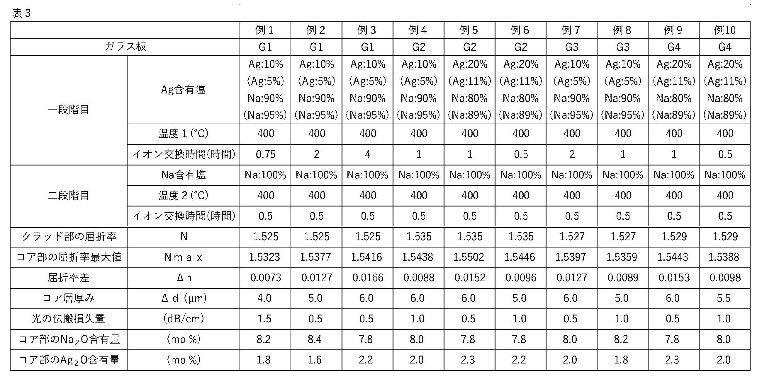
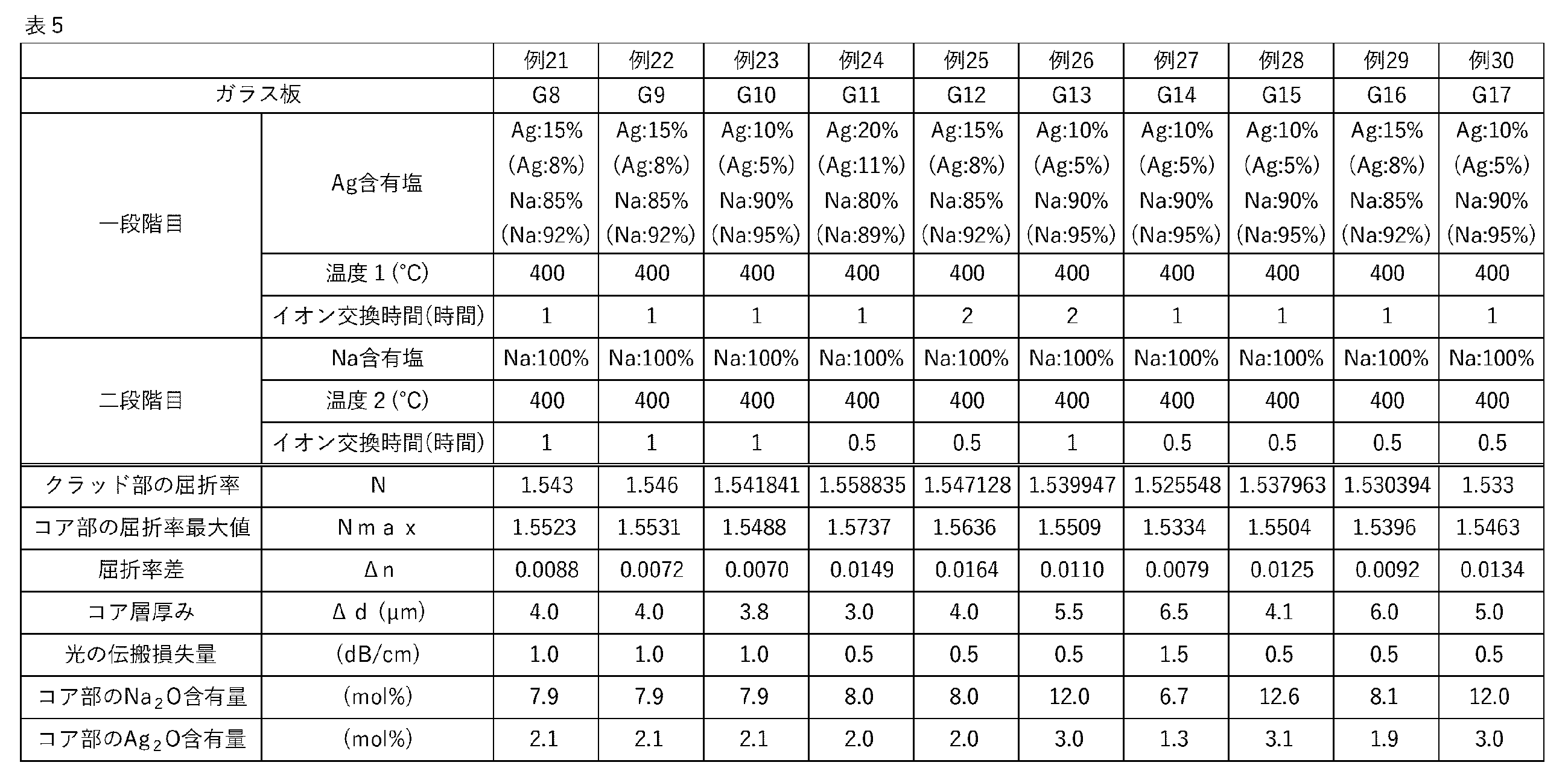
- Examples 1 to 36 The glass plates G1 to G20 obtained above were subjected to a two-stage ion exchange treatment under the conditions shown in Tables 3 to 6 to prepare glass substrates of Examples 1 to 36.
- a mixed molten salt of AgNO3 and NaNO3 was used as the Ag-containing salt.
- the ratio of Ag and Na to the total amount of cations in the mixed molten salt was as shown in "Ag-containing salt" in the table. The ratio is shown in mass % and in parentheses as cation %.
- a glass plate preheated to 200°C was immersed in the molten salt of each of the above Ag-containing salts.
- the temperature and immersion time of the molten salt are as shown in "Temperature 1 (°C)” and “Ion exchange time (hours)” in Tables 3 to 6.
- the glass plate was washed with warm water at about 60° C. and dried, and then the second stage of ion exchange treatment was carried out.
- a molten salt of NaNO3 was used as the Na-containing salt. Therefore, the ratio of Na to the total amount of cations in the molten salt was 100% in all cases.
- a glass plate preheated to 200°C was immersed in the molten salt of NaNO3 .
- the temperature of the molten salt and the immersion time are as shown in "Temperature 2 (°C)" and "Ion exchange time (hours)” in Tables 3 to 6.
- the glass plate was washed with warm water at about 60° C. and dried to obtain a glass substrate.
- the ion distribution of the obtained glass substrate after ion exchange treatment was measured from the surface to a depth of 100 ⁇ m by an electron beam microanalyzer method.
- the amount of Ag and the amount of Na at the point where the amount of Ag ions in the glass is maximum can be regarded as the Ag 2 O content and the Na 2 O content in the glass of the core part that becomes the optical waveguide, respectively, and are shown in Tables 3 to 6 as "Ag 2 O content in core part" and "Na 2 O content in core part". Note that other elements such as Si are not listed in the tables because there was no change in composition from the glass before ion exchange treatment, i.e., the glass that becomes the clad part.
- the refractive index of the glass plate before ion exchange was measured as the refractive index N of the cladding portion.
- the refractive index of light with a wavelength of 589 nm was measured using an automatic refractive index measuring instrument (KPR3000, manufactured by Shimadzu Corporation).
- the refractive index of the highest refractive index point of the glass substrate obtained through the two-stage ion exchange treatment was measured as the maximum refractive index Nmax using a two-beam interferometer (TD-10020, manufactured by Mizojiri Optical Co., Ltd.).
- the highest refractive index point means the point where the refractive index was measured every 0.5 ⁇ m in the depth direction from the glass substrate surface and the maximum refractive index was observed. It was also confirmed that the refractive index decreased as the thickness from the glass substrate surface increased. From the Nmax and N measured above, the refractive index difference ⁇ n expressed as (Nmax ⁇ N) was calculated.
- the core portion is a region where the refractive index is equal to or greater than the value expressed by ⁇ N+( ⁇ n/2) ⁇ , and the core layer thickness ⁇ d in the thickness direction of the glass substrate in the core portion was calculated from the results of measuring the refractive index in the depth direction using the two-beam interferometer (TD-10020, Mizojiri Optical Co., Ltd.) mentioned above.
- the refractive index N of the cladding, the maximum refractive index Nmax of the core, the refractive index difference ⁇ n, and the core layer thickness ⁇ d are summarized in Tables 3 to 6.
- the glass substrate obtained through the two-stage ion exchange process was used to determine the amount of propagation loss of light with a wavelength of 1550 nm in the core portion. Specifically, an optical waveguide with a waveguide length of 10 mm and an optical waveguide with a waveguide length of 22 mm were used to determine the amount of insertion loss of each. Then, the insertion loss at a length of 10 mm was defined as IL10, the insertion loss at a length of 22 mm was defined as IL22, and the propagation loss per unit length was determined by the so-called cutback method using the formula (IL22-IL10)/(2.2-1.0) (dB/cm). From the obtained results, the maximum value of the propagation loss of light was determined. The results are summarized in Tables 3 to 6.
- the glass substrates of Examples 1 to 31 produced using the glass plates G1 to G18 have a refractive index difference ⁇ n of 0.005 or more and a core layer thickness ⁇ d within the range of 2.5 to 10 ⁇ m, and therefore can transmit light propagated in a single mode.
- the glass substrates of Examples 32 and 33 have a core layer thickness ⁇ d of less than 2.5 ⁇ m, and cannot confine light when there is a curved region as an optical waveguide.
- the glass substrates of Examples 34 and 35 have a core layer thickness ⁇ d of more than 10 ⁇ m, and cannot transmit light propagated in a single mode.
- the glass substrate of Example 36 has a low refractive index difference ⁇ n of 0.0044, and the light confinement is weak, so the light cannot be propagated sufficiently.
Landscapes
- Chemical & Material Sciences (AREA)
- Engineering & Computer Science (AREA)
- Materials Engineering (AREA)
- Chemical Kinetics & Catalysis (AREA)
- General Chemical & Material Sciences (AREA)
- Geochemistry & Mineralogy (AREA)
- Life Sciences & Earth Sciences (AREA)
- Organic Chemistry (AREA)
- Physics & Mathematics (AREA)
- Optics & Photonics (AREA)
- Microelectronics & Electronic Packaging (AREA)
- General Physics & Mathematics (AREA)
- Glass Compositions (AREA)
- Optical Integrated Circuits (AREA)
Abstract
Description
電気信号に代えて光信号を用いることにより、低消費電力、大容量通信及び低遅延伝送といった点が期待される。
例えば特許文献1では、ガラス中のNaイオンをAgイオンにイオン交換することで光導波路とし得ることが開示されている。
[1] 光導波路となるコア部と、クラッド部と、を有するガラス基板であって、
前記コア部及び前記クラッド部は、共にガラスからなり、
前記コア部は前記クラッド部よりもAg濃度が高く、
前記コア部と前記クラッド部との境界から、前記コア部のうちAg濃度が最大となる領域に向けて、Agの濃度勾配があり、
前記コア部における屈折率の最大値Nmaxと、前記クラッド部の屈折率Nとを用いて、(Nmax-N)で表される屈折率差をΔnとすると、
前記コア部は、屈折率が{N+(Δn/2)}で表される値以上となる領域であり、
前記屈折率差Δnは0.005以上であり、
前記コア部の、前記ガラス基板の厚み方向におけるコア厚みΔdは2.5~10μmである、ガラス基板。
[2] 前記クラッド部のガラスは、酸化物基準のモル百分率表示での含有量が、
SiO2 45~80%、
Al2O3 0~15%、
B2O3 0~20%、
MgO、CaO、SrO及びBaOの合計 10~30%、並びに、
Na2O 4.5~25%、を満たし、
前記コア部のガラスは、酸化物基準のモル百分率表示での含有量が、
SiO2 45~80%、
Al2O3 0~15%、
B2O3 0~20%、
MgO、CaO、SrO及びBaOの合計 10~30%、
Na2O 0~20%、並びに、
Ag2O 0.01%以上、を満たす、前記[1]に記載のガラス基板。
[3] 前記クラッド部のガラスは、酸化物基準のモル百分率表示での含有量を用いて、(MgO+CaO+SrO×2+BaO×2-Al2O3×2)で表される値が0~30%である、前記[1]又は[2]に記載のガラス基板。
[4] 前記クラッド部のガラスは、酸化物基準のモル百分率表示での含有量を用いて、(MgO+CaO×2+SrO×3+BaO×4-Al2O3×2)で表される値が0~60%である、前記[1]~[3]のいずれか1に記載のガラス基板。
[5] 前記クラッド部のガラスは、酸化物基準のモル百分率表示での含有量を用いて、{Na2O/(MgO+CaO×2+SrO×3+BaO×4)}で表される値が0.1~0.7である、前記[1]~[4]のいずれか1に記載のガラス基板。
[6] 前記クラッド部のガラスは、酸化物基準のモル百分率表示での含有量を用いて、{Na2O/(MgO+CaO×2+SrO×3+BaO×4-Al2O3)}で表される値が0.1~2である、前記[1]~[5]のいずれか1に記載のガラス基板。
[7] 厚みが100~2000μmである、前記[1]~[6]のいずれか1に記載のガラス基板。
[8] 前記コア部における波長1200~1600nmの光の伝搬損失量が、最大で5.0dB/cm以下である、前記[1]~[7]のいずれか1に記載のガラス基板。
[9] 前記屈折率差Δnが0.007以上である、前記[1]~[8]のいずれか1に記載のガラス基板。
[10] 前記コア厚みΔdが3~6μmである、前記[1]~[9]のいずれか1に記載のガラス基板。
[11] 前記[1]~[10]のいずれか1に記載のガラス基板と、半導体基板と、が接続され、
シングルモード伝搬された光が、前記ガラス基板の前記コア部を介して、前記半導体基板に導入される、光集積デバイス。
本実施形態に係るガラス基板は、光導波路となるコア部と、クラッド部とを有し、コア部及びクラッド部は、共にガラスからなる。
コア部はクラッド部よりもAg濃度が高く、コア部とクラッド部との境界から、コア部のうちAg濃度が最大となる領域に向けて、Agの濃度勾配がある。
コア部における屈折率の最大値Nmaxと、クラッド部の屈折率Nとを用いて、(Nmax-N)で表される屈折率差をΔnとすると、コア部は、屈折率が{N+(Δn/2)}で表される値以上となる領域である。
上記屈折率差Δnは0.005以上である。また、ガラス基板の厚み方向におけるコア部のコア厚みΔdは2.5~10μmである。
コア部が同断面視において略円形である場合には、略円形の中心に近い領域のAg濃度が高く、中心から離れるにつれてAg濃度が低くなる。
コア部が同断面視において扇形である場合には、2本の半径の交点に近い領域のAg濃度が高く、交点から離れるにつれてAg濃度が低くなる。なお、扇形の弧となる部分が、同断面視において、鉛直方向下側に位置する形状である場合であって、上記交点がガラス基板の最表面やそれに近い場所に位置する場合には、コア部の上部に、屈折率の低い層を別途設けることにより、コア部が光導波路として機能する。上記屈折率の低い層は特に限定されず、当該屈折率の低い層がクラッド部として機能する。
なお本明細書における屈折率とは、波長589nmの光の屈折率である。
ここで、ガラス基板10の表層からの深さと、各深さにおける屈折率とは、図2のグラフに示したような関係となる。そして、光導波路となるコア部1の屈折率の方がクラッド部2の屈折率よりも高いことから、ガラス基板10表面からの深さ方向に屈折率を測定した際に最も高い屈折率を、コア部1における屈折率の最大値Nmaxとしてよい。
そして、屈折率が{N+(Δn/2)}以上となるコア部1の板厚方向の深さの最大値を、コア部1のガラス基板10の厚み方向におけるコア厚みΔdとする。
SiO2 45~80%、
Al2O3 0~15%、
B2O3 0~20%、
MgO、CaO、SrO及びBaOの合計 10~30%、並びに、
Na2O 4.5~25%。
図3に、実際に得られたガラス基板におけるクラッド部のガラス組成における式(1);(MgO+CaO+SrO×2+BaO×2-Al2O3×2)で表される値と、イオン交換処理をした際のAgイオンの侵入深さとの関係を示す。なお、上記イオン交換処理は、NaNO3:AgNO3=99:1(質量比)の混合溶融塩を用い、400℃の上記混合溶融塩に1時間ガラス基板を浸漬させることにより行った。また、図3におけるAgイオンの侵入深さは、折原製作所製の光導波表面応力計を用いてガラス表面からの屈折率分布を測定した際に、屈折率がイオン交換処理前のガラスの屈折率と一致する、ガラス表面からの深さを採用した。
式(1)で表される値は、0~30%が好ましく、2.5~27.5%がより好ましく、5~25%がさらに好ましく、7.5~22.5%がよりさらに好ましく、10~20%が特に好ましい。ここで、コア部のコア厚みΔdの制御性の観点から、式(1)で表される値は0%以上が好ましく、2.5%以上がより好ましく、5%以上がさらに好ましく、7.5%以上がよりさらに好ましく、10%以上が特に好ましい。また、生産性の観点から、式(1)で表される値は30%以下が好ましく、27.5%以下がより好ましく、25%以下がさらに好ましく、22.5%以下がよりさらに好ましく、20%以下が特に好ましい。
図4に、実際に得られたガラス基板におけるクラッド部のガラス組成における式(2);(MgO+CaO×2+SrO×3+BaO×4-Al2O3×2)で表される値と、イオン交換処理をした際のAgイオンの侵入深さとの関係を示す。なお、イオン交換処理やAgイオンの侵入深さの測定方法は、上記式(1)の検討で用いたイオン交換処理及びAgイオンの侵入深さの測定方法と同様である。
式(2)で表される値は、0~60%が好ましく、5~55%がより好ましく、10~50%がさらに好ましく、15~45%がよりさらに好ましく、20~40%が特に好ましい。ここで、コア部のコア厚みΔdの制御性の観点から、式(2)で表される値は0%以上が好ましく、5%以上がより好ましく、10%以上がさらに好ましく、15%以上がよりさらに好ましく、20%以上が特に好ましい。また、生産性の観点から、式(2)で表される値は60%以下が好ましく、55%以下がより好ましく、50%以下がさらに好ましく、45%以下がよりさらに好ましく、40%以下が特に好ましい。
図5に、実際に得られたガラス基板におけるクラッド部のガラス組成における式(3);{Na2O/(MgO+CaO×2+SrO×3+BaO×4)}で表される値と、イオン交換処理をした際のAgイオンの侵入深さとの関係を示す。なお、イオン交換処理やAgイオンの侵入深さの測定方法は、上記式(1)の検討で用いたイオン交換処理及びAgイオンの侵入深さの測定方法と同様である。
式(3)で表される値は、0.1~0.7が好ましく、0.125~0.6がより好ましく、0.15~0.5がさらに好ましく、0.175~0.45がよりさらに好ましく、0.2~0.4が特に好ましい。ここで、生産性の観点から、式(3)で表される値は0.1以上が好ましく、0.125以上がより好ましく、0.15以上がさらに好ましく、0.175以上がよりさらに好ましく、0.2以上が特に好ましい。また、コア部のコア厚みΔdの制御性の観点から、式(3)で表される値は0.7以下が好ましく、0.6以下がより好ましく、0.5以下がさらに好ましく、0.45以下がよりさらに好ましく、0.4以下が特に好ましい。
図6に、実際に得られたガラス基板におけるクラッド部のガラス組成における式(4);{Na2O/(MgO+CaO×2+SrO×3+BaO×4-Al2O3)}で表される値と、イオン交換処理をした際のAgイオンの侵入深さとの関係を示す。なお、イオン交換処理やAgイオンの侵入深さの測定方法は、上記式(1)の検討で用いたイオン交換処理及びAgイオンの侵入深さの測定方法と同様である。
式(4)で表される値は、0.1~2が好ましく、0.125~1.5がより好ましく、0.15~1がさらに好ましく、0.175~0.8がよりさらに好ましく、0.2~0.5が特に好ましい。ここで、生産性の観点から、式(4)で表される値は0.1以上が好ましく、0.125以上がより好ましく、0.15以上がさらに好ましく、0.175以上がよりさらに好ましく、0.2以上が特に好ましい。また、コア部のコア厚みΔdの制御性の観点から、式(4)で表される値は2以下が好ましく、1.5以下がより好ましく、1以下がさらに好ましく、0.8以下がよりさらに好ましく、0.5以下が特に好ましい。
なお、本明細書において「実質的に含有しない」とは、原材料等に含まれる不可避の不純物を除いて含有しない、すなわち、意図的に含有させたものではないことを意味する。具体的には、ガラス組成中の含有量が、0.1モル%未満であることを指す。
また、As2O3は実質的に含有しないことが好ましい。Sb2O3を含有する場合は、0.3%以下が好ましく、0.1%以下がより好ましく、実質的に含有しないことがよりさらに好ましい。
SiO2 45~80%、
Al2O3 0~15%、
B2O3 0~20%、
MgO、CaO、SrO及びBaOの合計 10~30%、
Na2O 0~20%、並びに、
Ag2O 0.01%以上。
また、本実施形態に係るガラス基板は上記に限らず、プラガブルデバイスにも搭載できる。
本実施形態に係るガラス基板の製造方法は、上記<ガラス基板>に記載したものが得られれば特に限定されないが、例えば、下記工程を含む。
(i)Na2Oを含むガラス板を用意する工程、
(ii)上記ガラス板の光導波路とする領域をAgイオンを含む溶融塩に接触させ、ガラスのNaイオンをAgイオンにイオン交換する工程。
ガラスを製造する際は従来公知の方法を採用できる。例えば、ガラスの各成分の原料を調合し、ガラス溶融窯で加熱溶融する。その後、公知の方法によりガラスを均質化し、所望の形状に成形し、徐冷することでガラス板を得る。
その後、成形したガラスを必要に応じて研削および研磨処理して、ガラス板を形成する。
マスキングは、溶融塩に反応せず、溶融塩と接触してもガラスを構成する成分と溶融塩の成分とのイオン交換を阻害するものであればよい。例えば、Al2O3、SiO2、SiN、TiO2、ITO等を用いてマスキングを行う。
他の塩としては、硝酸塩、硫酸塩、炭酸塩、塩化物などが挙げられる。このうち硝酸塩としては、硝酸リチウム、硝酸ナトリウム、硝酸カリウム、硝酸セシウム等が挙げられる。硫酸塩としては、硫酸リチウム、硫酸ナトリウム、硫酸カリウム、硫酸セシウム等が挙げられる。炭酸塩としては、炭酸リチウム、炭酸ナトリウム、炭酸カリウム等が挙げられる。塩化物としては、塩化リチウム、塩化ナトリウム、塩化カリウム、塩化セシウム等が挙げられる。
中でも、ガラスに不用意に応力を入れない観点から、硝酸ナトリウム、硫酸ナトリウム、炭酸ナトリウム、塩化ナトリウムを含むことが好ましく、硝酸ナトリウム、硫酸ナトリウムがより好ましい。
上記他の塩は単独で用いてもよいし、複数種を組み合わせて用いてもよい。
(iii)工程(ii)で得られたガラス板をNaイオンを含む溶融塩に接触させ、工程(ii)でイオン交換されたガラス中のAgイオンの一部を再度Naイオンにイオン交換する工程。
工程(ii)においてマスキングを行った場合、工程(iii)では、マスキングされたままのガラス板をNaイオンを含む溶融塩に接触させて、非マスキング部の表面付近のAgイオンをNaイオンにイオン交換してもよい。また、マスキングを除去して、ガラス板全体をNaイオンを含む溶融塩に接触させてもよい。
なお、工程(iii)を経ない場合には、先述したように、コア部が光導波路として機能するように、コア部の上部に屈折率の低い層を別途設ければよい。
他の塩としては、硝酸塩、硫酸塩、炭酸塩、塩化物などが挙げられる。このうち硝酸塩としては、硝酸リチウム、硝酸カリウム、硝酸セシウム等が挙げられる。硫酸塩としては、硫酸リチウム、硫酸カリウム、硫酸セシウム等が挙げられる。炭酸塩としては、炭酸リチウム、炭酸カリウム等が挙げられる。塩化物としては、塩化リチウム、塩化カリウム、塩化セシウム等が挙げられる。
中でも、化学的安定性の観点から、硝酸塩を含むことが好ましい。
上記他の塩は単独で用いてもよいし、複数種を組み合わせて用いてもよい。
洗浄の条件は用いる洗浄液によっても異なるが、イオン交換水を用いる場合には、付着した塩を完全に除去させる観点から、0~100℃で洗浄することが好ましい。
洗浄する工程では、イオン交換水等が入っている水槽にガラス板を浸漬する方法、ガラス板表面を流水にさらす方法、シャワーにより洗浄液をガラス板表面に向けて噴射する方法等、様々な方法を採用できる。
なお、例1~例36はいずれも、ガラス基板に対してマスキングを行うことなくイオン交換を行ったため、光導波路となるコア部とクラッド部とを有するガラス基板ではない。しかしながら、イオン交換前の母ガラスの屈折率と、イオン交換後の屈折率の変化は、マスキングを行ってイオン交換を行い、光導波路となるコア部を形成した場合と同じと見做せる。また、イオン交換により形成されるコア厚みΔdも、マスキングを行ってイオン交換を行い、光導波路となるコア部を形成した場合と同じと見做せる。そのため、例1~例36の結果は、光導波路となるコア部とクラッド部とを有するガラス基板の結果と同視でき、実質的に実施例又は比較例として扱える。したがって、例1~例31が実施例であり、例32~例36は比較例である。
表1及び表2に記載の、酸化物基準のモル百分率表示で示した組成、かつ、ガラス重量が400gとなるようにガラス原料を秤量し、混合した。混合した原料を白金るつぼに入れ、1500~1700℃の電気炉にて3時間程度溶融し、脱泡及び均質化を行った。なお、表中の空欄である成分は意図的に添加していないことを意味する。
得られたガラスブロックを切断、研削し、最後に両面を鏡面研磨して、20mm×20mm×0.7mmであるG1~G20のガラス板を得た。


上記で得られたG1~G20のガラス板に対し、表3~表6に記載した条件で二段階のイオン交換処理を施し、例1~例36のガラス基板を作製した。
一段階目のイオン交換処理は、Ag含有塩として、AgNO3とNaNO3の混合溶融塩を用いた。混合溶融塩中のカチオン総量に対するAgとNaとの割合は表中の「Ag含有塩」に記載のとおりとした。なお、上記割合は質量%表示と、括弧書きでカチオン%表示とを並記している。上記各Ag含有塩の溶融塩に、200℃に予熱したガラス板を浸漬させた。溶融塩の温度及び浸漬時間は、表3~表6の「温度1(℃)」及び「イオン交換時間(時間)」に記載のとおりである。
一段階目のイオン交換処理を行った後、60℃程度の温水でガラス板の洗浄を行い、乾燥させてから、次の二段階目のイオン交換処理を行った。
NaNO3の溶融塩に、200℃に予熱したガラス板を浸漬させた。溶融塩の温度及び浸漬時間は、表3~表6の「温度2(℃)」及び「イオン交換時間(時間)」に記載のとおりである。
二段階目のイオン交換処理を行った後、60℃程度の温水でガラス板の洗浄を行い、乾燥させ、ガラス基板を得た。


イオン交換前のガラス板の屈折率を、クラッド部の屈折率Nとして測定した。測定は、自動屈折率測定器(KPR3000、島津製作所社製)を用いて、波長589nmの光の屈折率を測定した。
二段階のイオン交換処理を経て得られたガラス基板に対し、最も屈折率が高い場所の屈折率を、屈折率の最大値Nmaxとして、二光束干渉計(TD-10020、溝尻光学社製)を用いて測定した。最も屈折率が高い場所とは、ガラス基板表面から、深さ方向に0.5μmごとに屈折率を測定していき、屈折率の極大が観測された箇所を意味する。なお、その後、ガラス基板表面からの厚さが深くなるにつれて屈折率が減少していくことも確認した。
上記で測定されたNmaxとNより、(Nmax-N)で表される屈折率差Δnを求めた。
二段階のイオン交換処理を経て得られたガラス基板を用いて、コア部における波長1550nmの光の伝搬損失量を求めた。具体的には、導波路長が10mmの光導波路と、導波路長が22mmの光導波路を用いて、それぞれの挿入損失量を求めた。そして、長さ10mmの時の挿入損失をIL10とし、長さ22mmの時の挿入損失をIL22とし、(IL22-IL10)/(2.2-1.0)(dB/cm)の式を用いる、いわゆるカットバック法によって、単位長さ当たりの伝搬損失量を求めた。得られた結果から、光の伝搬損失量の最大値を求めた。結果を表3~表6にまとめた。
一方、例32、例33のガラス基板はコア層厚みΔdが2.5μm未満となり、光導波路として曲がった領域があった場合に光を閉じ込めておけない。また、例34、例35のガラス基板はコア層厚みΔdが10μm超となりシングルモード伝搬された光を伝導できない。また、例36のガラス基板は屈折率差Δnが0.0044と低く、光の閉じ込めが弱いために、光を十分に伝搬できない。
Claims (11)
- 光導波路となるコア部と、クラッド部と、を有するガラス基板であって、
前記コア部及び前記クラッド部は、共にガラスからなり、
前記コア部は前記クラッド部よりもAg濃度が高く、
前記コア部と前記クラッド部との境界から、前記コア部のうちAg濃度が最大となる領域に向けて、Agの濃度勾配があり、
前記コア部における屈折率の最大値Nmaxと、前記クラッド部の屈折率Nとを用いて、(Nmax-N)で表される屈折率差をΔnとすると、
前記コア部は、屈折率が{N+(Δn/2)}で表される値以上となる領域であり、
前記屈折率差Δnは0.005以上であり、
前記コア部の、前記ガラス基板の厚み方向におけるコア厚みΔdは2.5~10μmである、ガラス基板。 - 前記クラッド部のガラスは、酸化物基準のモル百分率表示での含有量が、
SiO2 45~80%、
Al2O3 0~15%、
B2O3 0~20%、
MgO、CaO、SrO及びBaOの合計 10~30%、並びに、
Na2O 4.5~25%、を満たし、
前記コア部のガラスは、酸化物基準のモル百分率表示での含有量が、
SiO2 45~80%、
Al2O3 0~15%、
B2O3 0~20%、
MgO、CaO、SrO及びBaOの合計 10~30%、
Na2O 0~20%、並びに、
Ag2O 0.01%以上、を満たす、請求項1に記載のガラス基板。 - 前記クラッド部のガラスは、酸化物基準のモル百分率表示での含有量を用いて、(MgO+CaO+SrO×2+BaO×2-Al2O3×2)で表される値が0~30%である、請求項1に記載のガラス基板。
- 前記クラッド部のガラスは、酸化物基準のモル百分率表示での含有量を用いて、(MgO+CaO×2+SrO×3+BaO×4-Al2O3×2)で表される値が0~60%である、請求項1に記載のガラス基板。
- 前記クラッド部のガラスは、酸化物基準のモル百分率表示での含有量を用いて、{Na2O/(MgO+CaO×2+SrO×3+BaO×4)}で表される値が0.1~0.7である、請求項1に記載のガラス基板。
- 前記クラッド部のガラスは、酸化物基準のモル百分率表示での含有量を用いて、{Na2O/(MgO+CaO×2+SrO×3+BaO×4-Al2O3)}で表される値が0.1~2である、請求項1に記載のガラス基板。
- 厚みが100~2000μmである、請求項1に記載のガラス基板。
- 前記コア部における波長1200~1600nmの光の伝搬損失量が、最大で5.0dB/cm以下である、請求項1に記載のガラス基板。
- 前記屈折率差Δnが0.007以上である、請求項1に記載のガラス基板。
- 前記コア厚みΔdが3~6μmである、請求項1に記載のガラス基板。
- 請求項1~10のいずれか1項に記載のガラス基板と、半導体基板と、が接続され、
シングルモード伝搬された光が、前記ガラス基板の前記コア部を介して、前記半導体基板に導入される、光集積デバイス。
Priority Applications (4)
| Application Number | Priority Date | Filing Date | Title |
|---|---|---|---|
| DE112024000303.6T DE112024000303T5 (de) | 2023-01-31 | 2024-01-24 | Glassubstrat und integrierte photonikvorrichtung |
| JP2024574498A JPWO2024162147A1 (ja) | 2023-01-31 | 2024-01-24 | |
| CN202480009793.5A CN120603795A (zh) | 2023-01-31 | 2024-01-24 | 玻璃基板和光集成器件 |
| US19/285,414 US20250355178A1 (en) | 2023-01-31 | 2025-07-30 | Glass substrate and optical integrated device |
Applications Claiming Priority (2)
| Application Number | Priority Date | Filing Date | Title |
|---|---|---|---|
| JP2023-013069 | 2023-01-31 | ||
| JP2023013069 | 2023-01-31 |
Related Child Applications (1)
| Application Number | Title | Priority Date | Filing Date |
|---|---|---|---|
| US19/285,414 Continuation US20250355178A1 (en) | 2023-01-31 | 2025-07-30 | Glass substrate and optical integrated device |
Publications (1)
| Publication Number | Publication Date |
|---|---|
| WO2024162147A1 true WO2024162147A1 (ja) | 2024-08-08 |
Family
ID=92146625
Family Applications (1)
| Application Number | Title | Priority Date | Filing Date |
|---|---|---|---|
| PCT/JP2024/002112 Ceased WO2024162147A1 (ja) | 2023-01-31 | 2024-01-24 | ガラス基板及び光集積デバイス |
Country Status (6)
| Country | Link |
|---|---|
| US (1) | US20250355178A1 (ja) |
| JP (1) | JPWO2024162147A1 (ja) |
| CN (1) | CN120603795A (ja) |
| DE (1) | DE112024000303T5 (ja) |
| TW (1) | TW202432487A (ja) |
| WO (1) | WO2024162147A1 (ja) |
Citations (5)
| Publication number | Priority date | Publication date | Assignee | Title |
|---|---|---|---|---|
| JP2004067404A (ja) * | 2002-08-01 | 2004-03-04 | Ohara Inc | アモルファスガラス組成物 |
| JP2005075706A (ja) * | 2003-09-03 | 2005-03-24 | Fdk Corp | イオン交換型光導波路およびその製造方法 |
| WO2005080284A1 (ja) * | 2004-02-20 | 2005-09-01 | Isuzu Glass Co., Ltd. | 光学素子の製造方法 |
| JP2019522821A (ja) * | 2016-07-15 | 2019-08-15 | コーニング インコーポレイテッド | 積層構造を有する光導波路物品およびそれを形成する方法 |
| JP2021511538A (ja) * | 2018-01-18 | 2021-05-06 | コーニング インコーポレイテッド | Ag−Naイオン交換を用いて高透過ガラスに形成された低損失導波路 |
-
2024
- 2024-01-24 JP JP2024574498A patent/JPWO2024162147A1/ja active Pending
- 2024-01-24 DE DE112024000303.6T patent/DE112024000303T5/de active Pending
- 2024-01-24 CN CN202480009793.5A patent/CN120603795A/zh active Pending
- 2024-01-24 WO PCT/JP2024/002112 patent/WO2024162147A1/ja not_active Ceased
- 2024-01-29 TW TW113103290A patent/TW202432487A/zh unknown
-
2025
- 2025-07-30 US US19/285,414 patent/US20250355178A1/en active Pending
Patent Citations (5)
| Publication number | Priority date | Publication date | Assignee | Title |
|---|---|---|---|---|
| JP2004067404A (ja) * | 2002-08-01 | 2004-03-04 | Ohara Inc | アモルファスガラス組成物 |
| JP2005075706A (ja) * | 2003-09-03 | 2005-03-24 | Fdk Corp | イオン交換型光導波路およびその製造方法 |
| WO2005080284A1 (ja) * | 2004-02-20 | 2005-09-01 | Isuzu Glass Co., Ltd. | 光学素子の製造方法 |
| JP2019522821A (ja) * | 2016-07-15 | 2019-08-15 | コーニング インコーポレイテッド | 積層構造を有する光導波路物品およびそれを形成する方法 |
| JP2021511538A (ja) * | 2018-01-18 | 2021-05-06 | コーニング インコーポレイテッド | Ag−Naイオン交換を用いて高透過ガラスに形成された低損失導波路 |
Also Published As
| Publication number | Publication date |
|---|---|
| JPWO2024162147A1 (ja) | 2024-08-08 |
| TW202432487A (zh) | 2024-08-16 |
| DE112024000303T5 (de) | 2025-09-25 |
| US20250355178A1 (en) | 2025-11-20 |
| CN120603795A (zh) | 2025-09-05 |
Similar Documents
| Publication | Publication Date | Title |
|---|---|---|
| TWI789464B (zh) | 黑色矽酸鋰玻璃陶瓷 | |
| CN109608047A (zh) | 一种高结晶度钠霞石透明微晶玻璃及其制备方法 | |
| JP7248020B2 (ja) | 化学強化用ガラス | |
| KR20090027259A (ko) | 강화 유리 기판 | |
| JP7722372B2 (ja) | ガラスおよび化学強化ガラス | |
| CN105008297A (zh) | 假想化的玻璃及其制备方法 | |
| WO2022181812A1 (ja) | 化学強化ガラスの製造方法及び化学強化ガラス | |
| CN111253087B (zh) | 一种局部增强型玻璃制品及其加工方法 | |
| JP3899825B2 (ja) | 光導波路素子及びその製造方法 | |
| CN112110646B (zh) | 玻璃材料、梯度折射率玻璃及其制造方法 | |
| CN112110645B (zh) | 一种玻璃、玻璃制品及其制造方法 | |
| US20250355178A1 (en) | Glass substrate and optical integrated device | |
| WO2025020782A1 (zh) | 一种化学强化玻璃及其制备方法 | |
| WO2025142451A1 (ja) | 光導波路基板及び光学装置 | |
| US20060083474A1 (en) | Potassium free zinc silicate glasses for ion-exchange processes | |
| JP2025101491A (ja) | ガラス及びその製造方法 | |
| TW202344485A (zh) | 玻璃、化學強化玻璃及覆蓋玻璃 | |
| JP2002211947A (ja) | 屈折率分布型レンズ用母材ガラス組成物 | |
| CN112110644A (zh) | 玻璃组合物和化学强化玻璃 | |
| CN112079565A (zh) | 玻璃组合物、梯度折射率玻璃及其制造方法 | |
| TW202028139A (zh) | 具有三維形狀之玻璃物品及其製造方法、化學強化玻璃物品及其製造方法 | |
| US20260078051A1 (en) | Chemically strengthened glass, method for producing chemically strengthened glass, cover glass, and solar cell module | |
| JP4179821B2 (ja) | アモルファスガラス組成物 | |
| HK40097667A (zh) | 锂铝硅酸盐玻璃组合物、锂铝硅酸盐玻璃及其制备方法 | |
| HK40097667B (zh) | 锂铝硅酸盐玻璃组合物、锂铝硅酸盐玻璃及其制备方法 |
Legal Events
| Date | Code | Title | Description |
|---|---|---|---|
| 121 | Ep: the epo has been informed by wipo that ep was designated in this application |
Ref document number: 24750096 Country of ref document: EP Kind code of ref document: A1 |
|
| ENP | Entry into the national phase |
Ref document number: 2024574498 Country of ref document: JP Kind code of ref document: A |
|
| WWE | Wipo information: entry into national phase |
Ref document number: 2024574498 Country of ref document: JP |
|
| WWE | Wipo information: entry into national phase |
Ref document number: 112024000303 Country of ref document: DE |
|
| WWE | Wipo information: entry into national phase |
Ref document number: 202480009793.5 Country of ref document: CN |
|
| WWP | Wipo information: published in national office |
Ref document number: 202480009793.5 Country of ref document: CN |
|
| WWP | Wipo information: published in national office |
Ref document number: 112024000303 Country of ref document: DE |
|
| 122 | Ep: pct application non-entry in european phase |
Ref document number: 24750096 Country of ref document: EP Kind code of ref document: A1 |