WO2024157956A1 - 液滴吐出ヘッドおよび液滴吐出装置 - Google Patents
液滴吐出ヘッドおよび液滴吐出装置 Download PDFInfo
- Publication number
- WO2024157956A1 WO2024157956A1 PCT/JP2024/001771 JP2024001771W WO2024157956A1 WO 2024157956 A1 WO2024157956 A1 WO 2024157956A1 JP 2024001771 W JP2024001771 W JP 2024001771W WO 2024157956 A1 WO2024157956 A1 WO 2024157956A1
- Authority
- WO
- WIPO (PCT)
- Prior art keywords
- flow path
- droplet ejection
- branch flow
- ejection head
- path member
- Prior art date
- Legal status (The legal status is an assumption and is not a legal conclusion. Google has not performed a legal analysis and makes no representation as to the accuracy of the status listed.)
- Ceased
Links
Images






Classifications
-
- B—PERFORMING OPERATIONS; TRANSPORTING
- B41—PRINTING; LINING MACHINES; TYPEWRITERS; STAMPS
- B41J—TYPEWRITERS; SELECTIVE PRINTING MECHANISMS, i.e. MECHANISMS PRINTING OTHERWISE THAN FROM A FORME; CORRECTION OF TYPOGRAPHICAL ERRORS
- B41J2/00—Typewriters or selective printing mechanisms characterised by the printing or marking process for which they are designed
- B41J2/005—Typewriters or selective printing mechanisms characterised by the printing or marking process for which they are designed characterised by bringing liquid or particles selectively into contact with a printing material
- B41J2/01—Ink jet
-
- B—PERFORMING OPERATIONS; TRANSPORTING
- B41—PRINTING; LINING MACHINES; TYPEWRITERS; STAMPS
- B41J—TYPEWRITERS; SELECTIVE PRINTING MECHANISMS, i.e. MECHANISMS PRINTING OTHERWISE THAN FROM A FORME; CORRECTION OF TYPOGRAPHICAL ERRORS
- B41J2/00—Typewriters or selective printing mechanisms characterised by the printing or marking process for which they are designed
- B41J2/005—Typewriters or selective printing mechanisms characterised by the printing or marking process for which they are designed characterised by bringing liquid or particles selectively into contact with a printing material
- B41J2/01—Ink jet
- B41J2/135—Nozzles
- B41J2/14—Structure thereof only for on-demand ink jet heads
Definitions
- This disclosure relates to a droplet ejection head and a droplet ejection device.
- Patent Document 1 discloses a technology that reduces heat transferred from the driver IC to the head body via the heat sink by providing a heat insulating section between the head body, in which the ink flow paths and ejection holes are formed, and a heat sink located above the head body and dissipating heat from the driver IC.
- a droplet ejection head has a head body, a driver IC, a heat sink, and a heat insulating member.
- the head body has a plurality of ejection holes from which droplets are ejected.
- the driver IC controls the driving of the head body.
- the heat sink dissipates heat generated by the driver IC.
- the heat insulating member is located between the head body and the heat sink. Furthermore, the droplet ejection head has a gap formed between the heat sink and the heat insulating member.
- FIG. 1 is a schematic side view of a printer according to a first embodiment.
- FIG. 2 is a schematic plan view of the printer according to the first embodiment.
- FIG. 3 is an exploded perspective view showing a schematic configuration of the droplet ejection head according to the first embodiment.
- FIG. 4 is a cross-sectional view taken along line IV-IV shown in FIG.
- FIG. 5 is an enlarged cross-sectional view of the droplet ejection head according to the first embodiment.
- FIG. 6 is a perspective view for explaining the structure of the heat insulating member according to the first embodiment.
- FIG. 7 is a perspective view for explaining the structure of the heat insulating member according to the first embodiment.
- FIG. 8 is a schematic front view of the droplet ejection head according to the first embodiment.
- FIG. 9 is a schematic front view of the droplet ejection head according to the first embodiment.
- FIG. 10 is an enlarged perspective view of the droplet ejection head according to the first embodiment.
- FIG. 11 is an exploded perspective view showing a schematic configuration of a droplet ejection head according to the second embodiment.
- FIG. 12 is a schematic perspective view showing the configuration of a wiring board, a first support member, and a second support member according to the second embodiment.
- FIG. 13 is a schematic perspective view showing the configuration of a pressing member according to the second embodiment.
- FIG. 14 is a cross-sectional view taken along line XIV-XIV in FIG.
- FIG. 15 is a schematic cross-sectional view showing the configuration of one end of a droplet ejection head according to a modified example of the second embodiment.
- drawings referred to below may show an orthogonal coordinate system in which the X-axis, Y-axis, and Z-axis directions are defined as being perpendicular to each other, and the positive direction of the Z-axis is the vertically upward direction. Also, the direction of rotation about the vertical axis may be referred to as the ⁇ direction.
- Patent Document 1 discloses a technology that reduces heat transferred from the driver IC to the head body via the heat sink by providing an insulating section between the head body, in which the ink flow paths and ejection holes are formed, and a heat sink located above the head body and dissipating heat from the driver IC. This reduces the heat transfer from the heat sink to the ejection holes of the head body, and reduces the possibility of an increase in temperature of the ejected liquid affecting the viscosity of the liquid, etc.
- Figure 1 is a schematic side view of the printer 1 according to the first embodiment
- Figure 2 is a schematic plan view of the printer 1 according to the first embodiment.
- the printer 1 according to the first embodiment is, for example, a color inkjet printer.
- the printer 1 includes a feed roller 2, a guide roller 3, an applicator 4, a head case 5, a plurality of transport rollers 6, a plurality of frames 7, a plurality of droplet ejection heads 8, a transport roller 9, a dryer 10, a transport roller 11, a sensor unit 12, and a recovery roller 13.
- the printer 1 further includes a control unit 14 that controls the feed roller 2, guide roller 3, coater 4, head case 5, multiple transport rollers 6, multiple frames 7, multiple droplet ejection heads 8, transport roller 9, dryer 10, transport roller 11, sensor unit 12, and recovery roller 13.
- the printer 1 records images or characters on the printing paper P by causing droplets to land on the printing paper P.
- the printing paper P is an example of a recording medium. Before use, the printing paper P is wound around the paper feed roller 2. The printer 1 then transports the printing paper P from the paper feed roller 2 through the guide roller 3 and the coater 4 into the inside of the head case 5.
- the applicator 4 applies the coating agent evenly to the printing paper P. This allows the printing paper P to be surface-treated, improving the printing quality of the printer 1.
- the head case 5 houses multiple transport rollers 6, multiple frames 7, and multiple droplet ejection heads 8. Inside the head case 5, a space is formed that is isolated from the outside, except for some parts that are connected to the outside, such as the part where the printing paper P enters and exits.
- At least one of the control factors such as temperature, humidity, and air pressure in the internal space of the head case 5 is controlled by the control unit 14 as necessary.
- the transport rollers 6 transport the printing paper P inside the head case 5 to the vicinity of the droplet ejection head 8.
- the frame 7 is a rectangular flat plate, and is positioned close to and above the print paper P being transported by the transport rollers 6. As shown in FIG. 2, the frame 7 is positioned so that its longitudinal direction is perpendicular to the transport direction of the print paper P. Inside the head case 5, multiple (e.g., four) frames 7 are positioned along the transport direction of the print paper P.
- the transport direction of the printing paper P is also referred to as the "sub-scanning direction,” and the direction perpendicular to the sub-scanning direction and parallel to the printing paper P is also referred to as the "main scanning direction.”
- the droplet ejection head 8 is supplied with liquid, such as ink, from a liquid tank (not shown).
- the droplet ejection head 8 ejects the droplets supplied from the liquid tank.
- the control unit 14 controls the droplet ejection head 8 based on data such as images or characters, and ejects droplets toward the printing paper P.
- the distance between the droplet ejection head 8 and the printing paper P is, for example, about 0.5 to 20 mm.
- the droplet ejection head 8 is fixed to the frame 7.
- the droplet ejection head 8 is fixed to the frame 7, for example, at both ends in the longitudinal direction.
- the droplet ejection head 8 is positioned so that its longitudinal direction is perpendicular to the transport direction of the printing paper P.
- the printer 1 according to the first embodiment is a so-called line printer in which the droplet ejection head 8 is fixed inside the printer 1.
- the printer 1 according to the first embodiment is not limited to a line printer, and may be a so-called serial printer.
- a serial printer is a printer that alternates between the operation of recording while moving the droplet ejection head 8 back and forth in a direction intersecting the transport direction of the print paper P, for example, in a direction that is approximately perpendicular, and the transport of the print paper P.
- FIG. 2 shows an example in which three droplet ejection heads 8 are positioned in the front and two in the rear in the transport direction of the print paper P, and the droplet ejection heads 8 are positioned in the transport direction of the print paper P such that the centers of the droplet ejection heads 8 do not overlap.
- the head group 8A is made up of multiple droplet ejection heads 8 positioned on one frame 7.
- the four head groups 8A are positioned along the transport direction of the print paper P.
- the same color ink is supplied to droplet ejection heads 8 belonging to the same head group 8A. This allows the printer 1 to print with four colors of ink using the four head groups 8A.
- the colors of ink ejected from each head group 8A are, for example, magenta (M), yellow (Y), cyan (C) and black (K).
- the control unit 14 controls each head group 8A to eject multiple colors of ink onto the printing paper P, thereby printing a color image on the printing paper P.
- a coating agent may be ejected onto the printing paper P from the droplet ejection head 8.
- the number of droplet ejection heads 8 included in one head group 8A, or the number of head groups 8A mounted on the printer 1, can be changed as appropriate depending on the object to be printed or the printing conditions. For example, if the color printed on the printing paper P is a single color and the area printable by one droplet ejection head 8 is printed, the number of droplet ejection heads 8 mounted on the printer 1 may be one.
- the print paper P that has been printed inside the head case 5 is transported to the outside of the head case 5 by transport rollers 9 and passes through the inside of the dryer 10.
- the dryer 10 dries the print paper P that has been printed.
- the print paper P that has been dried in the dryer 10 is transported by transport rollers 11 and collected by collection rollers 13.
- the printer 1 by drying the printing paper P with the dryer 10, it is possible to reduce adhesion between overlapping sheets of printing paper P wound up on the recovery roller 13 and rubbing of undried liquid.
- the sensor unit 12 is composed of a position sensor, a speed sensor, a temperature sensor, etc.
- the control unit 14 can determine the state of each part of the printer 1 based on information from the sensor unit 12 and control each part of the printer 1.
- the printer 1 described so far has been described as using printing paper P as the printing target (i.e., recording medium), but the printing target in the printer 1 is not limited to printing paper P.
- the printing target may be a roll of cloth, etc.
- the printer 1 may transport the print paper P on a transport belt instead of directly transporting the paper.
- the printer 1 can print on paper sheets, cut pieces of cloth, wood, tiles, etc.
- the printer 1 may also print wiring patterns for electronic devices by ejecting droplets containing conductive particles from the droplet ejection head 8.
- the printer 1 may also produce chemicals by ejecting a predetermined amount of liquid chemicals or droplets containing chemicals from the droplet ejection head 8 toward a reaction vessel or the like.
- the printer 1 may also include a cleaning unit that cleans the droplet ejection head 8.
- the cleaning unit cleans the droplet ejection head 8, for example, by wiping or capping.
- the wiping process is a process in which liquid adhering to the droplet ejection head 8 is removed, for example, by using a flexible wiper to wipe the surface from which the droplets are ejected.
- the capping process is carried out, for example, as follows: First, a cap is placed over the surface of the area where the droplets are to be ejected (this is called capping). This creates a nearly sealed space between the surface of the area where the droplets are to be ejected and the cap.
- Fig. 3 is an exploded perspective view showing a schematic configuration of the droplet ejection head 8 according to the first embodiment.
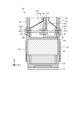
- Fig. 4 is a cross-sectional view taken along line IV-IV shown in Fig. 3.
- Fig. 5 is an enlarged cross-sectional view of the droplet ejection head 8 according to the first embodiment.
- the droplet ejection head 8 includes a head body 20, a wiring section 30, a head cover 40, two heat sinks 45, and two heat insulating members 50.
- the head body 20 includes a flow path member 21, a piezoelectric actuator substrate 22 (see FIG. 4), a branch flow path member 23, and a reservoir 24.
- the direction in which the head body 20 is provided in the droplet ejection head 8 may be referred to as “down” and the direction in which the head cover 40 is provided relative to the head body 20 may be referred to as "up.”
- the flow path member 21 of the head body 20 is generally flat and has one main surface, a first surface 21a (see FIG. 4), and a second surface 21b (see FIG. 4) located on the opposite side of the first surface.
- the first surface 21a has an opening (not shown), and liquid is supplied from the reservoir 24 to the inside of the flow path member 21 through this opening.
- the second surface 21b has a plurality of ejection holes (not shown) that eject droplets onto the printing paper P.
- the flow path member 21 has an internal flow path that allows liquid to flow from the first surface 21a to the second surface 21b.
- the piezoelectric actuator substrate 22 is located on the first surface 21a of the flow path member 21.
- the piezoelectric actuator substrate 22 has a plurality of displacement elements (not shown).
- the flexible substrate 31 of the wiring section 30 is electrically connected to the piezoelectric actuator substrate 22.
- the branch flow path member 23 is located on the flow path member 21.
- the branch flow path member 23 has a branch flow path (not shown) inside that is connected to the flow path of the flow path member 21.
- the branch flow path member 23 is made of a metal such as stainless steel (SUS430).
- the thermal conductivity of the branch flow path member 23 is, for example, 26 (W/m°C).
- the branch flow path member 23 is a box-shaped member that extends long in the main scanning direction (Y-axis direction) and has an open top.
- the branch flow path member 23 has a bottom 233, a peripheral wall portion 234 that stands up from the bottom 233, and two slit portions 235 (see FIG. 4).
- the bottom 233 is located on the flow path member 21.
- the peripheral wall portion 234 further has an eaves portion 234a that protrudes outward from the branch flow path member 23. This makes it possible to prevent the droplets discharged from the discharge holes of the flow path member 21 from scattering onto the heat sink 45 or the waterproof members 70a to 70e described below.
- the slit portion 235 is a groove-shaped gap that extends along the longitudinal direction (Y-axis direction) of the branch flow path member 23.
- the two slit portions 235 are arranged to sandwich the bottom portion 233 in a plan view.
- the flexible substrate 31 connected to the piezoelectric actuator substrate 22 is inserted into the slit portion 235.
- the reservoir 24 is located on the branch flow path member 23.
- the reservoir 24 has openings 24a at both ends in the main scanning direction (Y-axis direction). That is, the reservoir 24 has two openings 24a.
- the reservoir 24 has an internal flow path, and liquid is supplied from the outside through the openings 24a.
- the reservoir 24 supplies liquid to the branch flow path member 23.
- the reservoir 24 also stores the liquid supplied to the branch flow path member 23.
- liquid When printing, liquid may be supplied from one opening 24a while the other opening 24a is closed. Alternatively, liquid may be supplied from both openings 24a.
- liquid When initially introducing liquid into the droplet ejection head 8, if liquid is supplied from one opening 24a and collected from the other opening 24a, air and storage liquid that were in the flow path inside the reservoir 24 can easily escape from the flow path, making it easier to introduce liquid into the droplet ejection head 8.
- liquid may be supplied from one opening 24a and collected from the other opening 24a. In this way, air bubbles are less likely to accumulate in the flow path inside the reservoir 24. Furthermore, by supplying liquid adjusted to a constant temperature, the temperature of the droplet ejection head 8 can be stabilized.
- the collected liquid may be passed through a filter or the like and then supplied again to the droplet ejection head 8. In other words, the liquid may be circulated.
- the supply and collection of liquid to the droplet ejection head 8, or the circulation of the liquid may be controlled by the control unit 14.
- liquid may be supplied from the reservoir 24 to the flow path member 21, and liquid may be recovered from the flow path member 21 to the reservoir 24. Furthermore, liquid may be supplied to and recovered from the flow path facing the nozzle (ejection hole) within the flow path member 21, so that liquid is less likely to stagnate within the nozzle and its surroundings.
- liquid is supplied from the outside to the droplet ejection head 8 as a whole, some of the liquid is ejected from the ejection hole, and the liquid that is not ejected is recovered to the outside.
- the reservoir 24 may further include a heater substrate 24c and a heating resistor 24d.
- the heater substrate 24c brings the liquid flowing through the head body 20 closer to a predetermined temperature.
- a hole 24b that accommodates a fixing member 80 is formed on the side of the reservoir 24 that faces the heat sink 45.
- the wiring section 30 has a flexible substrate 31, a wiring substrate 32, a plurality of driver ICs 33, and a pressing member 34.
- the flexible substrate 31 is a flexible wiring substrate, and transmits a predetermined signal sent from the outside to the head body 20.
- the droplet ejection head 8 according to the first embodiment has two flexible substrates 31.
- One end of the flexible substrate 31 is electrically connected to the piezoelectric actuator substrate 22 of the head body 20 (see FIG. 4).
- the other end of the flexible substrate 31 is pulled out above the reservoir 24 and is electrically connected to the wiring substrate 32. This allows the piezoelectric actuator substrate 22 of the head body 20 to be electrically connected to the outside.
- the wiring board 32 is located above the head body 20.
- the wiring board 32 distributes signals to multiple driver ICs 33.
- the multiple driver ICs 33 are located on one of the main surfaces of the flexible substrate 31. As shown in FIG. 3, in the droplet ejection head 8 according to the first embodiment, two driver ICs 33 are provided on each flexible substrate 31. Note that the number of driver ICs 33 provided on each flexible substrate 31 is not limited to two.
- the driver IC 33 drives each displacement element in the piezoelectric actuator substrate 22 of the head body 20 based on the drive signal sent from the control unit 14 (see FIG. 1). In this way, the driver IC 33 drives the droplet ejection head 8.
- the pressing member 34 is, for example, a leaf spring having a roughly U-shape in cross section.
- the pressing member 34 is located between the two flexible substrates 31, and presses the driver IC 33 on the flexible substrate 31 towards the heat sink 45. This brings the driver IC into close contact with the heat sink 45, allowing the heat generated when the driver IC 33 is driven to be efficiently dissipated to the heat sink 45.
- the head cover 40 is attached to the head body 20 and is arranged so as to cover the wiring section 30 located on the head body 20, such as the flexible substrate 31, the wiring substrate 32, and the pressing member 34. This allows the head cover 40 to seal the wiring section 30.
- the head cover 40 is made of, for example, resin or metal.
- the head cover 40 is box-shaped and extends long in the main scanning direction, and has a first opening 40a and a second opening 40b on two opposing side surfaces along the sub-scanning direction.
- the first opening 40a is provided on the side surface located on the positive side of the X-axis
- the second opening 40b is provided on the side surface located on the negative side of the X-axis.
- the head cover 40 also has a third opening 40c on the bottom surface and a fourth opening 40d on the top surface.
- Two heat sinks 45 are attached to the head cover 40.
- One of the two heat sinks 45 is positioned to cover the first opening 40a, and the other is positioned to cover the second opening 40b.
- the heat sink 45 is, for example, a plate-like member that is long in the longitudinal direction of the droplet ejection head 8, and is made of a metal or alloy such as aluminum that has high heat dissipation properties.
- the thermal conductivity of the heat sink 45 is, for example, 236 (W/m°C).
- the heat sink 45 is provided so as to be in contact with the driver IC 33, and dissipates heat generated by the driver IC 33.
- Each of the two heat sinks 45 has a plurality of first through holes 46 that accommodate fixing members 80 (see FIG. 9).
- the head cover 40 has a plurality of through holes 41 that accommodate such fixing members 80.
- the two heat sinks 45 are each fixed to the head cover 40 by fixing members 80 (see FIG. 9).
- the head cover 40 with the heat sinks 45 attached has a box shape with the first opening 40a and the second opening 40b blocked and the third opening 40c and the fourth opening 40d open.
- the third opening 40c is positioned to face the reservoir 24.
- the flexible substrate 31 and the pressing member 34 are inserted into the third opening 40c.
- the fourth opening 40d is provided for inserting a connector (not shown) provided on the wiring board 32. If the space between the connector and the fourth opening 40d is sealed with resin or the like, it becomes difficult for liquid or dust to enter the inside of the head cover 40.
- the heat sink 45 also has second through holes 48a-48c at the center and both ends in the longitudinal direction of the head body 20.
- the second through holes 48a-48c accommodate the protrusions 54 of the heat insulating member 50, which will be described later.
- the heat insulating member 50 is located between the heat sink 45 and the head body 20.
- the width of the heat insulating member 50 in the longitudinal direction is wider than the width of the heat sink 45 in the longitudinal direction.
- the heat insulating member 50 is made of, for example, an epoxy-based resin.
- the thermal conductivity of the heat insulating member 50 may be lower than the thermal conductivity of the heat sink 45.
- the thermal conductivity of the heat insulating member 50 is, for example, 0.19 (W/m°C).
- FIG. 3 shows an example of the configuration of the droplet ejection head 8, and may further include components other than those shown in FIG. 3.
- the heat insulating member 50 has a lower thermal conductivity than the heat sink 45, and that the thermal conductivity is preferably about 1/1000 of that of the heat insulating member 50.
- FIGS. 6 and 7 are perspective views for explaining the structure of the insulating member 50 according to the first embodiment.
- the insulating member 50 is a member that extends long in the main scanning direction (Y-axis direction).
- the insulating member 50 has a first portion 51, a second portion 52, and a third portion 53 that connects the first portion 51 and the second portion 52.
- the insulating member 50 has a generally S-shaped cross section.
- the first portion 51 and the second portion 52 are positioned offset in the X-axis direction, with the first portion 51 being the portion that is closer to the reservoir 24 and the second portion 52 being the portion that is farther away from the reservoir 24.
- the third portion 53 connects the lower portion of the first portion 51 and the upper portion of the second portion 52.
- a gap is formed between the heat sink 45 and the insulating member 50.
- a first gap S1 is formed between the lower end surface of the heat sink 45 and the upper end surface of the second portion 52 of the insulating member 50.
- the second portion 52 of the insulating member 50 is located below the heat sink 45 with the first gap S1 interposed between them.
- a second gap S2 is also formed between the branch flow path member 23 and the heat insulating member 50. Specifically, as shown in Figs. 4 and 5, the second gap S2 is formed between the upper end surface of the peripheral wall portion 234 of the branch flow path member 23 and the lower end surface of the first portion 51 of the heat insulating member 50. In other words, the first portion 51 of the heat insulating member 50 is located above the peripheral wall portion 234 with the second gap S2 interposed between them.
- the first portion 51 has a first bonding surface 51a (see FIG. 5) facing the plate surface (side surface) of the heat sink 45.
- the heat insulating member 50 and the heat sink 45 are bonded to each other at the first bonding surface 51a and the plate surface of the heat sink 45.
- the second portion 52 has a second bonding surface 52a (see FIG. 5) facing the wall surface of the peripheral wall portion 234 of the branch flow path member 23.
- the heat insulating member 50 and the branch flow path member 23 are bonded to each other at the second bonding surface 52a and the wall surface of the peripheral wall portion 234.
- the first bonding surface 51a and the second bonding surface 52a face in opposite directions. Specifically, the first bonding surface 51a faces outward from the droplet discharge head 8, and the second bonding surface 52a faces inward from the droplet discharge head 8.
- the heat transfer path from the driver IC 33 to the flow path member 21 meanders in the insulating member 50.
- the heat transfer path becomes longer compared to a case where the heat transfer path is not meandering. Since the longer the heat transfer path, the greater the heat transfer loss, the more difficult it is to transfer the heat generated in the driver IC 33 to the flow path member 21.
- the bonding area between the heat sink 45 and the heat insulating member 50 is increased compared to, for example, when the heat insulating member 50 is bonded to the lower end surface of the heat sink 45, and the sealing ability of the droplet ejection head 8 can be improved.
- the bonding area between the branch flow path member 23 and the heat insulating member 50 is increased compared to, for example, when the heat insulating member 50 is bonded to the upper end surface of the peripheral wall portion 234, and the sealing ability of the droplet ejection head 8 can be improved.
- the surface 51b of the first portion 51 opposite the first bonding surface 51a faces the inside of the droplet ejection head 8 and may be inclined downward from the outside to the inside of the droplet ejection head 8. This allows a large space to be secured for passing the flexible substrate 31.
- the droplet ejection head 8 may have a waterproof member 70e between the insulating member 50 and the heat sink 45. This can prevent liquid from leaking out of the droplet ejection head 8. Details of the waterproof member 70e will be described later.
- the droplet ejection head 8 may have a waterproof member 70d between the heat insulating member 50 and the branch flow path member 23. This can prevent liquid from leaking out of the droplet ejection head 8. Details of the waterproof member 70d will be described later.
- the heat insulating member 50 has multiple (three in this example) protrusions 54 that fit into the second through holes 48a-48c at positions corresponding to the second through holes 48a-48c of the heat sink 45.
- the multiple protrusions 54 are located on the surface 51b of the first portion 51 of the heat insulating member 50 (see FIG. 5).
- the bonding area between the insulating member 50 and the heat sink 45 may be larger than the bonding area between the insulating member 50 and the branch flow path member 23. As shown in Figures 4 and 5, the bonding area between the insulating member 50 and the heat sink 45 is closer to the driver IC 33 than the bonding area between the insulating member 50 and the branch flow path member 23, and is more likely to become hot. Therefore, by increasing the bonding area between the insulating member 50 and the heat sink 45, more heat can be dissipated.
- the area of the waterproof member 70e located between the insulating member 50 and the heat sink 45 may also be larger than the area of the waterproof member 70d located between the insulating member 50 and the branch flow path member 23.
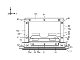
- Figs. 8 and 9 are schematic front views of the droplet ejection head 8 according to the first embodiment.
- Fig. 10 is an enlarged perspective view of the droplet ejection head 8 according to the first embodiment. Note that, for ease of understanding, Fig. 8 omits the illustration of the heat sink 45 and the fixing member 80. Fig. 10 also omits the illustration of the recess 47 of the heat sink 45, the recess 56 of the heat insulating member 50, and the fixing member 80.
- the heat sink 45 and the heat insulating member 50 are fitted together by fitting the protrusions 54 of the heat insulating member 50 into the second through holes 48a to 48c of the heat sink 45.
- the second through holes 48a, 48c located at both ends in the longitudinal direction are larger than the second through hole 48b located in the center in the longitudinal direction.
- the waterproof member 70e located between the insulating member 50 and the heat sink 45 may have adhesive properties.
- the insulating member 50 and the heat sink 45 may be bonded by the waterproof member 70e.
- the waterproof member 70e may be, for example, a double-sided tape, gel, or sealing resin.
- the waterproof member 70e is a double-sided tape, one adhesive surface of the waterproof member 70e is located on the wall surface of the heat sink 45, and the other adhesive surface is located on the first bonding surface 51a of the first part 51 of the insulating member 50. This can further improve the sealing performance of the droplet ejection head 8, making it less likely for liquid to leak.
- the waterproof member 70d (an example of a first waterproof member) located between the insulating member 50 and the branch flow path member 23 may have adhesive properties.
- the insulating member 50 may be bonded to the branch flow path member 23 and the reservoir 24 by the waterproof member 70d.
- double-sided tape, gel, or sealing resin may be used as the waterproof member 70d.
- the waterproof member 70d is double-sided tape, one adhesive surface of the waterproof member 70d is positioned so as to straddle the branch flow path member 23 and the reservoir 24, and the other adhesive surface is positioned on the insulating member 50. This can further improve the sealing performance of the droplet discharge head 8, making it less likely for liquid to leak.
- the head cover 40 and the heat sink 45 may be adhered by adhesive waterproof members 70a-70c (an example of a second waterproof member).
- the waterproof members 70a-70c may be made of double-sided tape, gel, or sealing resin, just like the waterproof member 70c.
- the waterproof members 70a-70c are double-sided tape, one adhesive surface of the waterproof members 70a-70c is located on the flange portion (the portion where the through hole 41 is provided) located on the periphery of the first opening 40a and the second opening 40b (FIG. 3) of the head cover 40, and the other adhesive surface is located on the heat sink 45. This can further improve the sealing of the droplet ejection head 8.
- the branch flow path member 23 and the reservoir 24 may be bonded by an adhesive waterproof member.
- the branch flow path member 23 and the reservoir 24 may be bonded at one end in the longitudinal direction by an adhesive waterproof member 90a (an example of a third waterproof member).
- the waterproof member 90a is, for example, double-sided tape. However, this is not limited, and the waterproof member 90a may be made of gel, sealing resin, or the like. This can improve the sealing ability of the branch flow path member 23 and the reservoir 24 and prevent the liquid from leaking out.
- the reservoir 24 and head cover 40, the heat sink 45 and the heat insulating member 50 are partially sealed with a caulking material.
- the droplet ejection head 8 has an area P1 in which neither the waterproof member 70c nor the waterproof member 70d is present in a part of the gap between the reservoir 24 and head cover 40 and the heat sink 45 and the heat insulating member 50.
- the caulking material is located in this area P1. That is, the caulking material is located across the reservoir 24 and the heat sink 45 and the heat insulating member 50 so as to close the gap between the reservoir 24 and the heat sink 45 and the heat insulating member 50 in which neither the waterproof member 70c nor the waterproof member 70d is present.
- the caulking material may be, for example, a resin. This allows the reservoir 24 and the heat sink 45 and the heat insulating member 50 to be fixed even between adjacent waterproof members, thereby further improving the sealing of the droplet ejection head 8.
- the insulating member 50 protrudes further in the longitudinal direction (Y-axis direction) of the head body 20 than the heat sink 45.
- the upper surface 50a of the insulating member 50 is located below the above-mentioned region P1.
- the branch flow path member 23, the reservoir 24, and the heat insulating member 50 are partially sealed with a caulking material.
- the droplet discharge head 8 has an area P2 where the waterproof member 90a and the waterproof member 70d contact each other in a part of the gap between the branch flow path member 23, the reservoir 24, and the heat insulating member 50.
- the caulking material is located in this area P2.
- the side surface (non-adhesive surface) of the waterproof member 90a contacts the waterproof member 70d, so sealing may be insufficient. Therefore, by sealing between the waterproof member 90a and the waterproof member 70d with a caulking material, the sealing property of the droplet discharge head 8 can be further improved.
- the branch flow path member 23, the reservoir 24, and the heat insulating member 50 can be fixed, and the sealing property of the droplet discharge head 8 can be further improved.
- the upper surface 23a of the eaves portion 234a of the branch flow path member 23 is located below the above-mentioned region P2. As a result, even if the pre-hardened caulking material applied to region P2 drips due to gravity during the manufacture of the droplet ejection head 8, the caulking material can be received by the upper surface 23a, making it possible to more reliably seal region P2 with the caulking material.
- the branch flow path member 23 and the reservoir 24, and the heat insulating member 50 are fixed by the fixing member 80.
- the branch flow path member 23, the reservoir 24, and the heat insulating member 50 are fixed by the fixing member 80 at both ends of the droplet ejection head 8 in the longitudinal direction.
- the fixing member 80 has a shaft portion having a spiral groove on the outer periphery, and a head portion located at the end of the shaft portion.
- a screw, a bolt, or a screw may be used as the fixing member 80. This makes it possible to fix the periphery of the portion fixed by the waterproof member 70d or the caulking material, and to further improve the sealing performance of the droplet ejection head 8.
- the heat insulating member 50 has multiple recesses 56 that accommodate the heads of the fixing members 80. This allows the amount of protrusion of the fixing members 80 to be reduced compared to when the recesses 56 are not present, and allows the droplet ejection head 8 to be made smaller in size in the short direction.
- FIG. 11 is an exploded perspective view showing a schematic configuration of the droplet discharge head 8a according to the second embodiment.
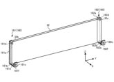
- FIG. 12 is a schematic perspective view showing the configuration of the wiring board 32, the first support member 161, and the second support member 162 according to the second embodiment.
- FIG. 13 is a schematic perspective view showing the configuration of the pressing member 163 according to the second embodiment.
- FIG. 14 is a cross-sectional view taken along line XIV-XIV in FIG. 11. In other words, FIG. 14 is a cross-sectional view of one end of the head main body 20 in the longitudinal direction.
- the support member 160 is omitted in FIG. 12.
- the same parts as those in the first embodiment are given the same symbols to omit redundant explanations.
- the droplet ejection head 8a shown in FIG. 11 differs from the droplet ejection head 8 according to the first embodiment shown in FIG. 3 mainly in the configuration of the wiring section 30.
- the droplet ejection head 8a according to the second embodiment includes a head body 20a, a wiring section 30a, a head cover 40, and two heat sinks 45, similar to the droplet ejection head 8 according to the first embodiment shown in FIG. 3.
- the head body 20a has a flow path member 21, a piezoelectric actuator substrate (not shown), a branch flow path member 23, and a reservoir 24.
- the wiring section 30a has a flexible substrate 31, a wiring substrate 32, a number of support members 160, a number of driver ICs 33, and a pressing member 163.
- the multiple support members 160 support the wiring board 32.
- the multiple support members 160 include a first support member 161 and a second support member 162.
- the first support member 161 is located at one end of the wiring board 32 in the longitudinal direction of the head body 20a.
- the first support member 161 has a base 161b, a support portion 161a extending vertically from one longitudinal end of the base 161b, and a fixed portion 161c extending vertically from the other longitudinal end of the base 161b.
- the wiring board 32 is located so that its bottom surface is located on the base 161b and one main surface is in contact with the support portion 161a.
- a through hole 161d is formed in the support portion 161a.
- the wiring board 32 has a through hole 32b penetrating both main surfaces at a position corresponding to the through hole 161d.
- Fixing members such as bolts or screws are inserted into the through holes 161d and 32b and screwed together, thereby fixing the wiring board 32 and the first support member 161.
- a through hole 161e is formed in the base portion 161b. Details of the fixing portion 161c will be described later.
- the second support member 162 is located at the other end of the wiring board 32 in the longitudinal direction of the head body 20a.
- the second support member 162 has a base 162b, a support portion 162a extending vertically from one longitudinal end of the base 162b, and a fixing portion 162c extending vertically from the other longitudinal end of the base 162b.
- the wiring board 32 is located so that its bottom surface is located on the base 162b and one main surface is in contact with the support portion 162a.
- a through hole 162d is formed in the support portion 162a.
- the wiring board 32 has a through hole 32b penetrating both main surfaces at a position corresponding to the through hole 161d.
- Fixing members such as bolts or screws are inserted into the through holes 161d and 32b and screwed together, thereby fixing the wiring board 32 and the second support member 162.
- a through hole 162e is formed in the base portion 162b. Details of the fixing portion 162c will be described later.
- the pressing member 163 has two side walls 163a and 163b, a bottom 163c, and two fixing parts 163d.
- the bottom 163c connects the lower ends of the two side wall portions 163a, 163b.
- the bottom 163c has a plurality of through holes 165 at both ends in the longitudinal direction of the head body 20.
- the reservoir 24 has a through hole (not shown) located at a position corresponding to the through hole 165.
- the branch flow path member 23 has a screw hole (not shown) located at a position corresponding to the through hole 165.
- a fixing member (not shown) such as a bolt or a screw is inserted through the through hole 165 of the bottom 163c of the pressing member 163 and the through hole of the reservoir 24.
- the fixing member (not shown) is screwed into the screw hole of the branch flow path member 23.
- the pressing member 163 is fixed to the branch flow path member 23, which is a highly rigid material, via the reservoir 24.
- the bottom 163c has a through hole 166a formed at a position corresponding to the through hole 161e (see FIG. 11) in the base 161b of the first support member 161.
- a fixing member such as a bolt or a screw is inserted through the through hole 166a and the through hole 161e.
- the fixing member (not shown) is screwed into a thread groove formed in the through hole 161e, for example. This fixes the first support member 161 to the pressing member 163.
- the bottom 163c has a through hole 166b formed at a position corresponding to the through hole 162e in the base 162b of the second support member 162.
- a fixing member such as a bolt or a screw is inserted through the through hole 166b and the through hole 162e.
- the fixing member (not shown) is screwed into a thread groove formed in the through hole 162e, for example. This fixes the second support member 162 to the pressing member 163.
- the first support member 161 is fixed to the pressing member 163, and is fixed to the branch flow path member 23 made of a highly rigid material via the pressing member 163 and the reservoir 24.
- the two fixing parts 163d are provided at both ends of one of the two side walls 163a, 163b (here, side wall 163b). In other words, the two fixing parts 163d are provided at both ends of the pressing member 163 in the longitudinal direction of the head body 20. The details of the fixing parts 163d will be described later.
- the pressing member 163 and the multiple support members 160 according to the second embodiment are fixed to the branch flow path member 23 made of a highly rigid material.
- the heat sink 45 according to the second embodiment is fixed to these pressing members 163 and the multiple support members 160 at both longitudinal ends of the head body 20. In the droplet ejection head 8a having such a configuration, the head cover 40 is unlikely to fall over even when an external force is applied to the heat sink 45.
- Figure 14 shows the configuration of the fixing point at one end of the droplet ejection head 8a in the longitudinal direction, and the configuration of the fixing point at the other end is omitted, but the fixing point at the other end has the same configuration as the fixing point at one end.
- a through hole 163e is formed in the fixing portion 163d of the pressing member 163.
- the head cover 40 has a through hole 41 located at a position corresponding to the through hole 163e.
- One of the two heat sinks 45 has a through hole 46 located at a position corresponding to the through hole 163e.
- the fixing member 180 is inserted through the through holes 163e, 41, and 46 and screwed together, whereby the pressing member 163, head cover 40, and heat sink 45 are fixed at one end in the longitudinal direction of the head body 20.
- a through hole 161f is formed in the fixing portion 161c of the first support member 161.
- the head cover 40 has a through hole 41 located at a position corresponding to the through hole 161f.
- the other of the two heat sinks 45 has a through hole 46 located at a position corresponding to the through hole 161f.
- a fixing member 181 is inserted and screwed through the through holes 161f, 41, and 46, and the first support member 161, head cover 40, and heat sink 45 are fixed at one end of the head body 20 in the longitudinal direction.
- the pressing member 163 or the second support member 162, the head cover 40, and the heat sink 45 are fixed by a fixing member.
- the heat sink 45 and the head cover 40 according to the second embodiment are fixed to members (here, the pressing member 163, the first support member 161, and the second support member 162) that are directly or indirectly fixed to the branch flow path member 23 at both ends of the head body 20 in the longitudinal direction.
- the droplet ejection head 8a according to the second embodiment may further include two plate members 170 that join the heat sink 45 and the head body 20.
- the plate member 170 is made of resin and joins the heat sink 45 and the branch flow path member 23 of the head body 20.
- the plate member 170 is a member that extends long in the main scanning direction (Y-axis direction).
- the width of the plate member 170 in the longitudinal direction is approximately the same as the width of the heat sink 45 in the longitudinal direction.
- the thermal conductivity of the plate member 170 may be lower than the thermal conductivity of the heat sink 45.
- the plate member 170 may be attached to the heat sink 45 and the branch flow path member 23 of the head body 20 using double-sided tape or adhesive.
- the droplet ejection head 8a is fixed at both longitudinal ends of the head body 20 to a member directly or indirectly fixed to the branch flow path member 23 and the heat sink 45. This increases the rigidity of the droplet ejection head 8a.
- the members fixed to the heat sink 45 and both ends of the head body 20 in the longitudinal direction are the pressing member 163 and the support member 160, but such members need only be members fixed directly or indirectly to at least the branch flow path member 23, and do not necessarily have to be the pressing member 163 and the support member 160.
- the member fixed to the heat sink 45 and both ends of the head body 20 in the longitudinal direction may be only the pressing member 163.
- the fixing portion 163d may be provided on both of the two side wall portions 163a, 163b (see FIG. 12) of the pressing member 163.
- the member fixed to the heat sink 45 and both ends of the head body 20 in the longitudinal direction may be only the support member 160, or may be another member.
- Fig. 15 is a schematic cross-sectional view showing the configuration of one end of the droplet ejection head 8a according to the modified example of the second embodiment. Note that in the following modified examples, the same parts as those in the second embodiment are designated by the same reference symbols, and duplicated explanations will be omitted.
- the fixing member for fixing the heat sink 45 to the pressing member 163 and the fixing member for fixing the heat sink 45 to the support member 160 may be fastened to the same member.
- the first support member 161 may have a tubular portion 167 with a screw groove formed on the inner circumferential surface.
- the tubular portion 167 is, for example, cylindrical.
- the tubular portion 167 may be inserted into a notch 161g provided in the support portion 161a of the first support member 161.
- the tubular portion 167 may also be formed integrally with the first support member 161.
- a first male screw 190 is inserted into the through hole 46 of one of the two heat sinks 45, the through hole 41 of the head cover 40, and the through hole 163e of the fixing portion 163d of the pressing member 163.
- the first male screw 190 is screwed into the tubular portion 167.
- one of the two heat sinks 45, the head cover 40, and the pressing member 163 are fixed at one end of the head body 20 in the longitudinal direction.
- a second male screw 191 is inserted through the through hole 46 of the other of the two heat sinks 45, the through hole 41 of the head cover 40, and the through hole 161e of the fixing portion 161c of the first support member 161.
- the second male screw 191 is screwed into the cylindrical portion 167, whereby the other of the two heat sinks 45, the head cover 40, and the first support member 161 are fixed at one end of the head body 20 in the longitudinal direction.
- the second support member 162 may have a cylindrical portion (not shown) with a threaded groove formed on its inner circumferential surface, and a first male screw (not shown) that fastens one of the two heat sinks 45 and the pressing member 163, and a second male screw (not shown) that fastens the other of the two heat sinks 45 and the second support member 162 may be fastened to the same cylindrical portion.
- the droplet ejection head 8a according to the second embodiment can further increase the rigidity of the droplet ejection head 8a by fastening the first male screw 190 and the second male screw 191 to the same cylindrical portion 167.
- the droplet ejection head (for example, the droplet ejection head 8) has a head body (for example, the head body 20), a driver IC (for example, the driver IC 33), a heat sink (for example, the heat sink 45), and an insulating member (for example, the insulating member 50).
- the head body has a plurality of ejection holes from which droplets are ejected.
- the driver IC controls the driving of the head body.
- the heat sink dissipates heat generated by the driver IC.
- the insulating member is located between the head body and the heat sink.
- the droplet ejection head has a gap (for example, a first gap S1) formed between the heat sink and the insulating member.
- the insulating member may have a first bonding surface (for example, first bonding surface 51a) at a position facing the plate surface of the heat sink, and the insulating member and the heat sink may be bonded at the first bonding surface and the plate surface.
- the heat sink has through holes (for example, second through holes 48a to 48c) at the center and both ends in the longitudinal direction of the head body, and the heat insulating member has protrusions (for example, protrusion 54) that fit into the through holes at positions corresponding to each through hole, and the through holes located at both ends in the longitudinal direction may be formed larger than the through hole located in the longitudinal center.
- through holes for example, second through holes 48a to 48c
- the heat insulating member has protrusions (for example, protrusion 54) that fit into the through holes at positions corresponding to each through hole, and the through holes located at both ends in the longitudinal direction may be formed larger than the through hole located in the longitudinal center.
- any one of the droplet ejection heads described above in (1) to (3) may have a waterproof member (for example, waterproof member 70e) between the insulating member and the heat sink.
- a waterproof member for example, waterproof member 70e
- the waterproof member may have adhesive properties, and the insulating member and the heat sink may be bonded by the waterproof member.
- the head body may have a flow path member (for example, flow path member 21) having an ejection hole, and a branch flow path member (for example, branch flow path member 23) located above the flow path member and having a branch flow path connected to the flow path member, and a gap (for example, second gap S2) may be formed between the branch flow path member and the insulating member.
- a flow path member for example, flow path member 21
- branch flow path member 23 located above the flow path member and having a branch flow path connected to the flow path member
- a gap for example, second gap S2
- the branch flow path member has a bottom portion (for example, bottom portion 233) located on the flow path member and a peripheral wall portion (for example, peripheral wall portion 234) standing up from the bottom portion, and the heat insulating member has a second bonding surface (for example, second bonding surface 52a) at a position facing the wall surface of the peripheral wall portion, and the heat insulating member and the branch flow path member may be bonded at the second bonding surface and the wall surface.
- the droplet ejection head of (6) or (7) above may have a waterproof member (for example, waterproof member 70d) between the heat insulating member and the branch flow path member.
- a waterproof member for example, waterproof member 70d
- the waterproof member may have adhesive properties, and the insulating member and the branch flow path member may be bonded by the waterproof member.
- the heat insulating member has a first portion (for example, first portion 51) having a first bonding surface that is bonded to the plate surface of the heat sink, a second portion (for example, second portion 52) having a second bonding surface, and a third portion (for example, third portion 53) connecting the first portion and the second portion, and the first portion may be located above the peripheral wall portion with a gap therebetween, and the second portion may be located below the heat sink with a gap therebetween.
- first portion for example, first portion 51
- second portion 52 having a second bonding surface
- third portion for example, third portion 53
- the surface opposite the first bonding surface of the first portion may face the inside of the droplet ejection head and slope downward from the outside to the inside of the droplet ejection head.
- the second portion may be located outside the droplet ejection head beyond the heat sink in a cross-sectional view of the droplet ejection head cut along a plane perpendicular to the longitudinal direction of the head body.
- the head body may have a flow path member having an ejection hole, and a branch flow path member located above the flow path member and having a branch flow path connected to the flow path member, and the bonding area between the heat insulating member and the heat sink may be larger than the bonding area between the heat insulating member and the branch flow path member.
- any one of the droplet ejection heads (1) to (13) above has a head cover (head cover 40, for example) attached to the head body, the head body has a flow path member having an ejection hole, a branch flow path member located on the flow path member and having a branch flow path connected to the flow path member, and a reservoir (reservoir 24, for example) located on the branch flow path member and supplying liquid to the branch flow path member, the heat insulating member, the branch flow path member, and the reservoir are bonded with a first waterproof member having adhesive properties (waterproof member 70d, for example), the head cover and the heat sink are bonded with a second waterproof member having adhesive properties (waterproof members 70a to 70c, for example), and the area (area P1, for example) where neither the first waterproof member nor the second waterproof member is present in the gap between the reservoir and head cover and the heat sink and the heat insulating member may be sealed with a caulking material.
- a first waterproof member having adhesive properties waterproof member 70d, for example
- the head body has a flow path member having an ejection hole, a branch flow path member located above the flow path member and having a branch flow path connected to the flow path member, and a reservoir located above the branch flow path member and supplying liquid to the branch flow path member, the heat insulating member, the branch flow path member, and the reservoir are bonded with a first waterproof member having adhesive properties, the branch flow path member and the reservoir are bonded with a third waterproof member having adhesive properties (for example, waterproof member 90a), and the area (for example, area P2) in the gap between the branch flow path member and the reservoir and the heat insulating member where the first waterproof member and the third waterproof member come into contact may be sealed with a caulking material.
- a droplet ejection device (for example, printer 1) may have any one of the droplet ejection heads (1) to (15) above and a control unit that controls the droplet ejection head.
Landscapes
- Ink Jet (AREA)
Priority Applications (1)
| Application Number | Priority Date | Filing Date | Title |
|---|---|---|---|
| JP2024552318A JP7649927B2 (ja) | 2023-01-23 | 2024-01-23 | 液滴吐出ヘッドおよび液滴吐出装置 |
Applications Claiming Priority (2)
| Application Number | Priority Date | Filing Date | Title |
|---|---|---|---|
| JP2023-008377 | 2023-01-23 | ||
| JP2023008377 | 2023-01-23 |
Publications (1)
| Publication Number | Publication Date |
|---|---|
| WO2024157956A1 true WO2024157956A1 (ja) | 2024-08-02 |
Family
ID=91970624
Family Applications (1)
| Application Number | Title | Priority Date | Filing Date |
|---|---|---|---|
| PCT/JP2024/001771 Ceased WO2024157956A1 (ja) | 2023-01-23 | 2024-01-23 | 液滴吐出ヘッドおよび液滴吐出装置 |
Country Status (2)
| Country | Link |
|---|---|
| JP (1) | JP7649927B2 (https=) |
| WO (1) | WO2024157956A1 (https=) |
Citations (3)
| Publication number | Priority date | Publication date | Assignee | Title |
|---|---|---|---|---|
| JP2000343690A (ja) * | 1999-03-29 | 2000-12-12 | Seiko Epson Corp | インクジェット記録装置 |
| JP2008018555A (ja) * | 2006-07-11 | 2008-01-31 | Brother Ind Ltd | 記録装置 |
| JP2013067145A (ja) * | 2011-09-26 | 2013-04-18 | Toshiba Tec Corp | インクジェットヘッド |
Family Cites Families (4)
| Publication number | Priority date | Publication date | Assignee | Title |
|---|---|---|---|---|
| JP3797137B2 (ja) | 2001-05-31 | 2006-07-12 | ブラザー工業株式会社 | インクジェット記録ヘッド |
| JP6253460B2 (ja) | 2014-03-12 | 2017-12-27 | エスアイアイ・プリンテック株式会社 | 液体噴射ヘッド及び液体噴射装置 |
| WO2016190413A1 (ja) | 2015-05-27 | 2016-12-01 | 京セラ株式会社 | 液体吐出ヘッド、および記録装置 |
| JP7366586B2 (ja) | 2019-05-17 | 2023-10-23 | 東芝テック株式会社 | 液体吐出ヘッド及び液体吐出装置 |
-
2024
- 2024-01-23 JP JP2024552318A patent/JP7649927B2/ja active Active
- 2024-01-23 WO PCT/JP2024/001771 patent/WO2024157956A1/ja not_active Ceased
Patent Citations (3)
| Publication number | Priority date | Publication date | Assignee | Title |
|---|---|---|---|---|
| JP2000343690A (ja) * | 1999-03-29 | 2000-12-12 | Seiko Epson Corp | インクジェット記録装置 |
| JP2008018555A (ja) * | 2006-07-11 | 2008-01-31 | Brother Ind Ltd | 記録装置 |
| JP2013067145A (ja) * | 2011-09-26 | 2013-04-18 | Toshiba Tec Corp | インクジェットヘッド |
Also Published As
| Publication number | Publication date |
|---|---|
| JP7649927B2 (ja) | 2025-03-21 |
| JPWO2024157956A1 (https=) | 2024-08-02 |
Similar Documents
| Publication | Publication Date | Title |
|---|---|---|
| JP7670890B2 (ja) | 液体吐出装置および液体吐出装置の組み立て方法 | |
| JP7640677B2 (ja) | 液体吐出ヘッド、吐出ヘッド構造体および記録装置 | |
| JP7649927B2 (ja) | 液滴吐出ヘッドおよび液滴吐出装置 | |
| JP2025089526A (ja) | 液体吐出ヘッドおよび記録装置 | |
| JP7570585B1 (ja) | 液滴吐出ヘッド | |
| JP2020019149A (ja) | 液体吐出ヘッド保護部材、液体吐出ヘッド及び液体を吐出する装置 | |
| WO2024157971A1 (ja) | 液滴吐出ヘッドおよび液滴吐出装置 | |
| WO2026004645A1 (ja) | 液滴吐出ヘッドおよび液滴吐出装置 | |
| JP7587090B1 (ja) | 液滴吐出ヘッド、記録装置および液滴吐出ヘッドの製造方法 | |
| JP7730416B2 (ja) | 液体吐出ヘッドおよび記録装置 | |
| JP2025059971A (ja) | 液滴吐出ヘッドおよび液滴吐出装置 | |
| WO2024225322A1 (ja) | 液滴吐出ヘッドおよび記録装置 | |
| JP7310335B2 (ja) | ヘッドモジュール、ヘッドユニット、液体を吐出する装置 | |
| WO2025047809A1 (ja) | 液滴吐出ヘッドおよび液滴吐出装置 | |
| WO2025028218A1 (ja) | 液滴吐出ヘッド | |
| JP7794992B2 (ja) | 液体吐出ヘッドおよび液体吐出装置 | |
| US20260034790A1 (en) | Liquid supply member, liquid discharge head, and recording device | |
| JP2025129960A (ja) | 液滴吐出ヘッドおよび液滴吐出装置 | |
| JP7753517B2 (ja) | 液体吐出ヘッドおよび記録装置 | |
| JP7803821B2 (ja) | 液体吐出ヘッドおよび記録装置 | |
| JP7615417B1 (ja) | 液滴吐出ヘッドおよび記録装置 | |
| JP7764439B2 (ja) | 液体吐出ヘッド及びその製造方法 | |
| JP2023128813A (ja) | 液体吐出ヘッドおよび記録装置 | |
| JP2023147123A (ja) | 液体吐出ヘッド及び記録装置 | |
| WO2024080101A1 (ja) | 液滴吐出ユニット、液滴吐出装置及び液滴吐出システム |
Legal Events
| Date | Code | Title | Description |
|---|---|---|---|
| WWE | Wipo information: entry into national phase |
Ref document number: 2024552318 Country of ref document: JP |
|
| 121 | Ep: the epo has been informed by wipo that ep was designated in this application |
Ref document number: 24747283 Country of ref document: EP Kind code of ref document: A1 |
|
| NENP | Non-entry into the national phase |
Ref country code: DE |
|
| 122 | Ep: pct application non-entry in european phase |
Ref document number: 24747283 Country of ref document: EP Kind code of ref document: A1 |