WO2024157740A1 - 回転電気機械 - Google Patents
回転電気機械 Download PDFInfo
- Publication number
- WO2024157740A1 WO2024157740A1 PCT/JP2023/047197 JP2023047197W WO2024157740A1 WO 2024157740 A1 WO2024157740 A1 WO 2024157740A1 JP 2023047197 W JP2023047197 W JP 2023047197W WO 2024157740 A1 WO2024157740 A1 WO 2024157740A1
- Authority
- WO
- WIPO (PCT)
- Prior art keywords
- magnetic
- tooth
- protrusion amount
- main body
- rotor
- Prior art date
- Legal status (The legal status is an assumption and is not a legal conclusion. Google has not performed a legal analysis and makes no representation as to the accuracy of the status listed.)
- Ceased
Links
Images


Classifications
-
- H—ELECTRICITY
- H02—GENERATION; CONVERSION OR DISTRIBUTION OF ELECTRIC POWER
- H02K—DYNAMO-ELECTRIC MACHINES
- H02K21/00—Synchronous motors having permanent magnets; Synchronous generators having permanent magnets
- H02K21/12—Synchronous motors having permanent magnets; Synchronous generators having permanent magnets with stationary armatures and rotating magnets
- H02K21/14—Synchronous motors having permanent magnets; Synchronous generators having permanent magnets with stationary armatures and rotating magnets with magnets rotating within the armatures
- H02K21/16—Synchronous motors having permanent magnets; Synchronous generators having permanent magnets with stationary armatures and rotating magnets with magnets rotating within the armatures having annular armature cores with salient poles
-
- H—ELECTRICITY
- H02—GENERATION; CONVERSION OR DISTRIBUTION OF ELECTRIC POWER
- H02K—DYNAMO-ELECTRIC MACHINES
- H02K1/00—Details of the magnetic circuit
- H02K1/06—Details of the magnetic circuit characterised by the shape, form or construction
- H02K1/12—Stationary parts of the magnetic circuit
- H02K1/14—Stator cores with salient poles
- H02K1/146—Stator cores with salient poles consisting of a generally annular yoke with salient poles
-
- H—ELECTRICITY
- H02—GENERATION; CONVERSION OR DISTRIBUTION OF ELECTRIC POWER
- H02K—DYNAMO-ELECTRIC MACHINES
- H02K1/00—Details of the magnetic circuit
- H02K1/06—Details of the magnetic circuit characterised by the shape, form or construction
- H02K1/22—Rotating parts of the magnetic circuit
- H02K1/27—Rotor cores with permanent magnets
- H02K1/2706—Inner rotors
- H02K1/272—Inner rotors the magnetisation axis of the magnets being perpendicular to the rotor axis
- H02K1/2726—Inner rotors the magnetisation axis of the magnets being perpendicular to the rotor axis the rotor consisting of a single magnet or two or more axially juxtaposed single magnets
- H02K1/2733—Annular magnets
-
- H—ELECTRICITY
- H02—GENERATION; CONVERSION OR DISTRIBUTION OF ELECTRIC POWER
- H02K—DYNAMO-ELECTRIC MACHINES
- H02K2201/00—Specific aspects not provided for in the other groups of this subclass relating to the magnetic circuits
- H02K2201/03—Machines characterised by aspects of the air-gap between rotor and stator
-
- H—ELECTRICITY
- H02—GENERATION; CONVERSION OR DISTRIBUTION OF ELECTRIC POWER
- H02K—DYNAMO-ELECTRIC MACHINES
- H02K2213/00—Specific aspects, not otherwise provided for and not covered by codes H02K2201/00 - H02K2211/00
- H02K2213/03—Machines characterised by numerical values, ranges, mathematical expressions or similar information
Definitions
- the present invention relates to rotating electrical machines.
- a known example of an invention relating to a conventional rotating electric machine is the motor described in Patent Document 1.
- the motor described in Patent Document 1 comprises a shaft that serves as the center of rotation when rotating a rotor relative to a stator, a magnet attached to the rotor and magnetized with alternating different poles in the circumferential direction around the axis, an iron core attached to the stator and facing the magnet in the radial direction around the axis, a coil wound around the iron core, and a magnetic shielding member.
- the magnetic shielding member blocks leakage magnetic flux from the magnet to the coil.
- the object of the present invention is to provide a rotating electric machine that can increase the back electromotive force constant while reducing the number of magnetic shielding members.
- a rotating electric machine comprises: A rotating electric machine including a rotor including a magnetized hard magnetic material and a magnetic core including a teeth portion,
- the teeth portion includes: a teeth main body portion around which a coil is wound, the teeth main body portion extending inward toward a rotation shaft of the rotor or outward in the opposite direction; a tooth tip portion formed at a tip of the tooth main body portion and facing the hard magnetic body; having the tooth tip portion includes a first protrusion protruding from the tooth body portion in an axial direction along the rotation axis, The amount of protrusion of the first protrusion from the tooth body is less than three times the width of a gap between the hard magnetic body and the tooth tip.
- the present invention provides a rotating electric machine that can increase the back electromotive force constant while reducing the number of magnetic shielding members.
- FIG. 1 is a perspective view of the appearance of a brushless motor 100.
- FIG. FIG. 2 is a schematic exploded perspective view of brushless motor 100.
- FIG. 3 is a perspective view of the magnetic core 1.
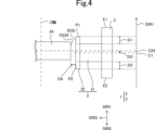
- FIG. 4 is a cross-sectional view of the hard magnetic body 24 and one magnetic core 1 viewed in a direction perpendicular to the first direction DIR1 and the third direction DIR3.
- FIG. 5 is a cross-sectional view of the hard magnetic body 24 and a magnetic core 6 according to one comparative example, viewed in a direction perpendicular to the first direction DIR1 and the third direction DIR3.
- FIG. 6 is a diagram showing the locations where the magnetic flux density is calculated.
- FIG. 7 is a diagram showing an example of the change in magnetic flux density when the first protrusion amount D1 and the second protrusion amount D2 are changed when the offset amount DO is 0.1 mm and the gap width DA is 0.5 mm.
- FIG. 8 is a diagram showing an example of the change in magnetic flux density when the first protrusion amount D1 and the second protrusion amount D2 are changed when the offset amount DO is 0.2 mm and the gap width DA is 0.5 mm.
- FIG. 9 is a diagram showing an example of the change in the counter electromotive force constant KE when the first protrusion amount D1 and the second protrusion amount D2 are changed when the offset amount DO is 0.2 mm and the gap width DA is 0.5 mm.
- FIG. 10 is a diagram showing an example of the change in the counter electromotive force constant KE when the first protrusion amount D1 and the second protrusion amount D2 are changed when the offset amount DO is 0.2 mm and the gap width DA is 0.3 mm.
- Fig. 1 is an external perspective view of the brushless motor 100.
- Fig. 2 is an exploded perspective schematic view of the brushless motor 100.
- Fig. 3 is a perspective view of a magnetic core 1.
- directions are defined as follows.
- first direction DIR1 The opposite direction of the first direction DIR1 is defined as a second direction DIR2.
- second direction DIR2 One of the radial directions centered on the rotation axis of the rotor 20, which is a direction from the geometric center of the teeth tip portion 32 toward the rotation axis of the rotor 20 as viewed in the first direction DIR1, is defined as a third direction DIR3.
- the counterclockwise direction with respect to the rotation axis of the rotor 20 as viewed in the second direction DIR2 is defined as a fourth direction DIR4. Note that the definitions of directions in this specification are merely examples.
- the brushless motor 100 includes a rotor 20 and a stator assembly 10.
- the stator assembly 10 is disposed around the rotor 20 when viewed in the first direction DIR1.
- the brushless motor 100 is an inner rotor type.
- the brushless motor 100 is an example of a rotating electric machine of the present invention.
- the rotor 20 includes a shaft 21 and a rotor member 22.
- the shaft 21 is cylindrical and extends in the first direction DIR1.
- the rotor member 22 is cylindrical and extends in the first direction DIR1.
- the central axes of the shaft 21 and the rotor member 22 are the Z-axis. In other words, the rotation axis of the brushless motor 100 is the Z-axis. Therefore, the first direction DIR1 and the second direction DIR2 are each a direction along the Z-axis.
- the rotor member 22 has a soft magnetic body 23 and a hard magnetic body 24.
- the rotor member 22 is attached to the outer peripheral surface of the shaft 21 in the radial direction centered on the Z axis. More specifically, the soft magnetic body 23 is attached to the outer peripheral surface of the shaft 21 in the radial direction centered on the Z axis.
- the hard magnetic body 24 is attached to the outer peripheral surface of the soft magnetic body 23 in the radial direction centered on the Z axis.
- the soft magnetic material 23 is a soft magnetic material.
- the hard magnetic material 24 is a magnetized hard magnetic material. The hard magnetic material becomes magnetized when a magnetic field is applied from the outside. Even if the application of the magnetic field is then stopped, the hard magnetic material does not lose its magnetization.
- the stator assembly 10 includes a bearing 11, a housing 12, a coil 13, and a magnetic core 1.
- the bearing 11 supports the shaft 21 so that it can rotate in the circumferential direction around the Z-axis. More specifically, as shown in FIG. 2, the bearing 11 has a first bearing 11a and a second bearing 11b. Each of the first bearing 11a and the second bearing 11b is, for example, a ball bearing. Each of the first bearing 11a and the second bearing 11b is cylindrical and extends in the first direction DIR1. The central axis of each of the first bearing 11a and the second bearing 11b is the Z-axis. In other words, the central axis of each of the first bearing 11a and the second bearing 11b coincides with the central axis of the shaft 21.
- the second bearing 11b is located further in the second direction DIR2 than the first bearing 11a.
- the first bearing 11a is located further in the first direction DIR1 than the rotor member 22.
- the second bearing 11b is located further in the second direction DIR2 than the rotor member 22.
- the second bearing 11b supports the end of the shaft 21 in the second direction DIR2.
- the housing 12 has a first housing 12a and a second housing 12b.
- the first housing 12a is cylindrical.
- the central axis of the first housing 12a is the Z-axis.
- the first housing 12a is located further in the first direction DIR1 than the second housing 12b.
- the first housing 12a also has an opening OP.
- the shaft 21 protrudes from the opening OP in the first direction DIR1.
- the brushless motor 100 is a single-shaft type.
- the first housing 12a supports the first bearing 11a, the multiple magnetic cores 1, and the multiple coils 13.
- the second housing 12b supports the second bearing 11b.
- the materials of the first housing 12a and the second housing 12b are, for example, a highly rigid material such as SUS.
- the number of coils 13 and the number of magnetic cores 1 are each nine.
- the nine coils 13 and the nine magnetic cores 1 are arranged in the circumferential direction centered on the Z-axis.
- the nine magnetic cores 1 are arranged around the hard magnetic material 24 with a gap between them.
- the magnetic core 1 has a core back portion 2 and teeth portion 3.
- the teeth portion 3 has a shape extending from the core back portion 2 in the third direction DIR3. More specifically, the teeth portion 3 has a teeth main body portion 31 extending from the core back portion 2 in the third direction DIR3, and a teeth tip portion 32 formed at the tip of the teeth main body portion 31.
- the coil 13 is wound around the teeth main body portion 31.
- the magnetic core 1 is a soft magnetic material. When an external magnetic field is applied to the soft magnetic material, it becomes magnetized. When the application of the magnetic field is then stopped, the soft magnetic material loses its magnetization.
- An example of the material of such a soft magnetic material is iron.
- the magnetic core 1 is a molded body made of soft magnetic powder. That is, each of the core back portion 2 and the teeth portion 3 is a molded body made of soft magnetic powder.
- the material of the soft magnetic powder includes, for example, iron and a binder.
- the binder is, for example, resin.
- the soft magnetic powder is, for example, a mixture of iron powder and epoxy resin, which is an example of a binder.
- Such a magnetic core 1 is produced, for example, by press molding. In addition, an insulating treatment is applied to the outer surface of the magnetic core 1 that comes into contact with another member.
- the core back portion 2 has a first end face E1 and a second end face E2 aligned in a first direction DIR1, an inner main surface and an outer main surface aligned in a third direction DIR3, and two side surfaces aligned in a fourth direction DIR4.
- the first end face E1 is located further in the first direction DIR1 than the second end face E2.
- the inner main surface is located further in the third direction DIR3 than the outer main surface.
- the first end face E1, the second end face E2, and the inner main surface are each flat.
- the outer main surface and the two side surfaces are each curved.
- Figure 4 is a cross-sectional view of the hard magnetic material 24 and one magnetic core 1 viewed in a direction perpendicular to the first direction DIR1 and the third direction DIR3.
- the tooth tip portion 32 includes a first protrusion P1 and a second protrusion P2.
- the first protrusion P1 protrudes from the tooth main body portion 31 in the first direction DIR1.
- the amount of protrusion of the first protrusion P1 from the tooth main body portion 31 in the first direction DIR1 is defined as a first protrusion amount D1.
- the second protrusion P2 protrudes from the tooth main body portion 31 in the second direction DIR2.
- the amount of protrusion of the second protrusion P2 from the tooth main body portion 31 in the second direction DIR2 is defined as a second protrusion amount D2.
- the first protrusion P1 is located in the second direction DIR2 further than the first end face E1.
- the second protrusion P2 is located in the first direction DIR1 from the second end face E2. That is, the first protrusion P1 and the second protrusion P2 are each located between the first end face E1 and the second end face E2 in the first direction DIR1.
- the tooth tip portion 32 faces the hard magnetic body 24 as shown in Figures 2 and 4. More specifically, the inner main surface IS32 of the tooth tip portion 32 in the third direction DIR3 faces the outer peripheral surface OS24 of the hard magnetic body 24 in the third direction DIR3 as shown in Figure 4. Also, as shown in Figure 2, there is an air gap between the magnetic core 1 and the rotor member 22. More specifically, as shown in Figure 4, there is an air gap between the inner main surface IS32 of the tooth tip portion 32 and the outer peripheral surface OS24 of the hard magnetic body 24. The distance between the tooth tip portion 32 and the hard magnetic body 24 is defined as the gap width DA. In this embodiment, the gap width DA is the distance in the third direction DIR3 between the inner main surface IS32 and the outer peripheral surface OS24.
- the magnetic center C24 of the hard magnetic body 24 and the magnetic center C1 of the magnetic core 1 are offset in the first direction DIR1. More specifically, the magnetic center C24 of the hard magnetic body 24 is located further in the first direction DIR1 than the magnetic center C1 of the magnetic core 1. The distance in the first direction DIR1 between the magnetic center C24 of the hard magnetic body 24 and the magnetic center C1 of the magnetic core 1 is defined as the offset amount DO.
- the coil 13 is made of a conductive material such as copper.
- the coil 13 has a structure in which the surface of the copper wire is covered with an insulating coating. Since the surface of the copper wire is covered with an insulating coating, the coil 13 and the magnetic core 1 are electrically insulated.
- the coil 13 is supplied with current from a power source (not shown). When current flows through the coil 13, the coil 13 generates a magnetic field.
- the magnetic core 1 is magnetized by both the magnetic field generated by the hard magnetic material 24 and the magnetic field generated by the coil 13.
- the rotation of the rotor 20 is controlled by controlling the current supplied from the power source (not shown).
- FIG. 5 is a cross-sectional view of the hard magnetic body 24 and the magnetic core 6 according to one comparative example, viewed in a direction perpendicular to the first direction DIR1 and the third direction DIR3.
- FIG. 6 is a diagram showing the calculation points of the magnetic flux density.
- FIG. 7 is a diagram showing an example of the change in magnetic flux density when the first protrusion amount D1 and the second protrusion amount D2 are changed when the offset amount DO is 0.1 mm and the gap width DA is 0.5 mm.
- FIG. 5 is a cross-sectional view of the hard magnetic body 24 and the magnetic core 6 according to one comparative example, viewed in a direction perpendicular to the first direction DIR1 and the third direction DIR3.
- FIG. 6 is a diagram showing the calculation points of the magnetic flux density.
- FIG. 7 is a diagram showing an example of the change in magnetic flux density when the first protrusion amount D1 and the second protrusion amount D2 are changed when the offset amount DO is 0.1
- FIG. 8 is a diagram showing an example of the change in magnetic flux density when the first protrusion amount D1 and the second protrusion amount D2 are changed when the offset amount DO is 0.2 mm and the gap width DA is 0.5 mm.
- FIG. 9 is a diagram showing an example of the change in the back electromotive force constant KE when the first protrusion amount D1 and the second protrusion amount D2 are changed when the offset amount DO is 0.2 mm and the gap width DA is 0.5 mm.
- Figure 10 shows an example of the change in the back electromotive force constant KE when the first protrusion amount D1 and the second protrusion amount D2 are changed when the offset amount DO is 0.2 mm and the gap width DA is 0.3 mm. Note that Figures 7 to 10 are the results of computer simulations. Also, for the magnetic core 6 according to the comparative example, only the parts that are different from the magnetic core 1 will be explained, and the rest will be omitted.
- the magnetic core 6 according to the comparative example differs from the magnetic core 1 in that the tooth tip 32 does not include the first protrusion P1 and the second protrusion P2, as shown in FIG. 5. That is, the tooth tip 32 does not protrude from the tooth main body 31 in the first direction DIR1. Moreover, the tooth tip 32 does not protrude from the tooth main body 31 in the second direction DIR2.
- the magnetic center C24 of the hard magnetic body 24 is located in the first direction DIR1 from the magnetic center C1 of the magnetic core 1. Therefore, the leakage flux B1 from the hard magnetic body 24 to the region located in the first direction DIR1 from the tooth main body 31 is greater than the leakage flux B2 from the hard magnetic body 24 to the region located in the second direction DIR2 from the tooth main body 31. Due to the difference between the leakage flux B1 and the leakage flux B2, the hard magnetic body 24 receives a force in the axial direction along the Z axis. This force causes noise and vibration in a brushless motor equipped with the magnetic core 6 of the comparative example.
- the inventors of the present application therefore discovered that when the tooth tip portion 32 includes the first protrusion P1 and the second protrusion P2, the difference between the leakage magnetic flux B1 and the leakage magnetic flux B2 becomes smaller, and the noise and vibration generated by the brushless motor 100 can be reduced.
- the inventors of the present application performed the following computer simulation.
- the first protrusion amount D1 is the protrusion amount of the first protrusion P1 from the tooth main body portion 31 in the first direction DIR1.
- the second protrusion amount D2 is the protrusion amount of the second protrusion P2 from the tooth main body portion 31 in the second direction DIR2.
- the gap width DA is the distance in the third direction DIR3 between the inner main surface IS32 and the outer peripheral surface OS24.
- the inventors of the present application calculated the change in magnetic flux density when the first protrusion amount D1 and the second protrusion amount D2 are changed.
- the average value of the magnetic flux density in the first region A1 is defined as the first direction magnetic flux density B1AVE.
- the average value of the magnetic flux density in the second region A2 is defined as the second direction magnetic flux density B2AVE.
- the first region A1 and the second region A2 are imaginary regions that are perpendicular to the first direction DIR1 and symmetrical with respect to a plane that includes the center of the magnetic core 1. As shown in FIG. 6, the first region A1 is located further in the first direction DIR1 than the teeth main body portion 31.
- the second region A2 is located further in the second direction DIR2 than the teeth main body portion 31.
- the magnetic core is magnetic core 6 according to the comparative example. Also, when the first protrusion amount D1 and the second protrusion amount D2 are greater than 0 mm, the magnetic core is magnetic core 1.
- the brushless motor 100 can reduce the noise and vibration generated by the brushless motor.
- the brushless motor 100 can reduce the noise and vibration generated by the brushless motor.
- the brushless motor 100 can reduce noise and vibration generated by the brushless motor without requiring a magnetic shielding member to block leakage magnetic flux from the hard magnetic body 24 to the coil 13.
- the inventors of the present application also discovered that when the tooth tip portion 32 includes the first protrusion portion P1 and the second protrusion portion P2, the back electromotive force constant KE changes in response to changes in the first protrusion amount D1 and the second protrusion amount D2.
- the inventors of the present application calculated the change in the back electromotive force constant KE when the first protrusion amount D1 and the second protrusion amount D2 are changed.
- the back electromotive force constant KE is a constant obtained by dividing the back electromotive force generated between both ends of the coil 13 by the angular velocity of the rotor 20.
- the back electromotive force constant KE is larger than the back electromotive force constant KE when the first protrusion amount D1 and second protrusion amount D2 are 0 mm (in the case of a brushless motor having a magnetic core 6 according to the comparative example). Therefore, if the first protrusion amount D1 and the second protrusion amount D2 are smaller than three times the gap width DA, the back electromotive force constant KE can be increased.
- the back electromotive force constant KE is larger than the back electromotive force constant KE when the first protrusion amount D1 and second protrusion amount D2 are 0 mm (in the case of a brushless motor having a magnetic core 6 according to the comparative example). Therefore, if the first protrusion amount D1 and the second protrusion amount D2 are smaller than three times the gap width DA, the back electromotive force constant KE can be increased.
- the magnetic flux generated by the hard magnetic body 24 is increased in the magnetic flux that is taken into the magnetic core 1 from the tooth tip portion 32.
- the first protrusion amount D1 and the second protrusion amount D2 ⁇ the gap width DA, most of the increased magnetic flux passes through the tooth main body portion 31, and the back electromotive force constant KE increases.
- the rotating electric machine according to the present invention is not limited to the brushless motor 100, and can be modified within the scope of the present invention.
- the rotating electric machine may have a structure in which the rotor is rotated by electricity, or a structure in which electricity is generated by the rotation of the rotor.
- Rotating electric machines include brushless motors, permanent magnet synchronous motors, permanent magnet synchronous generators, etc. In this case, the rotating electric machine may be equipped with brushes.
- the brushless motor 100 may be of an outer rotor type.
- the teeth main body 31 extends from the core back portion 2 in the opposite direction to the third direction DIR3.
- the teeth tip portion 32 is formed at the tip of the teeth main body 31.
- the back electromotive force constant KE is a constant obtained by dividing the back electromotive force generated between both ends of the coil 13 by the angular velocity of the rotor 20, it can be inferred that even when the brushless motor 100 is of an outer rotor type, the back electromotive force constant KE can be increased by making the first protrusion amount D1 and the second protrusion amount D2 smaller than three times the gap width DA, as in the above-mentioned embodiment. Therefore, even when the brushless motor 100 is of an outer rotor type, the same effect as when the brushless motor 100 is of an inner rotor type is achieved.
- the gap width DA may be the distance in the third direction DIR3 between the outer main surface of the tooth tip portion 32 and the outer peripheral surface OS24 of the hard magnetic body 24.
- the teeth main body 31 does not have to extend from the core back portion 2 in the third direction DIR3. In this case, the teeth main body 31 only needs to extend inward toward the rotation axis of the rotor 20.
- the back electromotive force constant KE is a constant obtained by dividing the back electromotive force generated between both ends of the coil 13 by the angular velocity of the rotor 20, when the brushless motor 100 is an inner rotor type, if the teeth main body 31 extends inward toward the rotation axis of the rotor 20, it can be inferred that the back electromotive force constant KE can be increased by making the first protrusion amount D1 and the second protrusion amount D2 smaller than three times the gap width DA, as in the above-mentioned embodiment.
- the teeth main body portion 31 does not have to extend from the core back portion 2 in the opposite direction to the third direction DIR3. In this case, the teeth main body portion 31 only needs to extend outward (opposite the inward direction toward the rotation axis of the rotor 20).
- the back electromotive force constant KE is a constant obtained by dividing the back electromotive force generated between both ends of the coil 13 by the angular velocity of the rotor 20, when the brushless motor 100 is an outer rotor type, it can be inferred that if the teeth main body portion 31 extends outward, the back electromotive force constant KE can be increased by making the first protrusion amount D1 and the second protrusion amount D2 smaller than three times the gap width DA, as in the above-mentioned embodiment.
- the brushless motor 100 is not limited to a single-shaft type.
- the brushless motor 100 may be, for example, a double-shaft type.
- first bearing 11a and the second bearing 11b are not limited to ball bearings.
- the materials for the first housing 12a and the second housing 12b may be any material that has high rigidity.
- the number of coils 13 and the number of magnetic cores 1 are not limited to nine.
- the magnetic core 1 may also be made by laminating electromagnetic steel sheets.
- the two end faces and the inner main surface of the core back portion 2 may each be curved.
- the outer main surface and the two side surfaces of the core back portion 2 may each be flat.
- the magnetic center C24 of the hard magnetic material 24 and the magnetic center C1 of the magnetic core 1 may coincide in the first direction DIR1.
- the offset amount DO is zero. Even in this case, the same effect as the brushless motor 100 is achieved.
- the tooth tip 32 may include at least one of the first protrusion P1 and the second protrusion P2.
- the back electromotive force constant KE may be an induced voltage constant, a power generation constant, or a torque constant.
- the present invention has the following configuration.
- a rotating electric machine including a rotor including a magnetized hard magnetic material and a magnetic core including a teeth portion
- the teeth portion includes: a teeth main body portion around which a coil is wound, the teeth main body portion extending inward toward a rotation shaft of the rotor or outward in the opposite direction; a tooth tip portion formed at a tip of the tooth main body portion and facing the hard magnetic body; having the tooth tip portion includes a first protrusion protruding from the tooth body portion in an axial direction along the rotation axis, a protruding amount of the first protruding portion from the tooth main body portion is smaller than three times a gap width when the hard magnetic body and the tooth tip portion face each other; Rotating electrical machines.
- the tooth tip portion includes a second protruding portion protruding from the tooth body portion in an axial direction opposite to the first protruding portion, A protruding amount of the second protruding portion from the tooth main body is less than three times the gap width.
- the magnetic core is a compact formed from soft magnetic powder.
- a rotating electric machine according to any one of (1) to (4).
- Magnetic core 2 Core back portion 3: Teeth portion 6: Magnetic core 10: Stator assembly 11: Bearing 11a: First bearing 11b: Second bearing 12: Housing 12a: First housing 12b: Second housing 13: Coil 20: Rotor 21: Shaft 22: Rotor member 23: Soft magnetic material 24: Hard magnetic material 31: Teeth main body portion 32: Teeth tip portion 100: Brushless motor A1: First region A2: Second region B1, B2: Magnetic flux B1AVE: First direction side magnetic flux density B2AVE: Second direction side magnetic flux density C1, C24: Magnetic center D1: First protrusion amount D2: Second protrusion amount DA: Gap width DIR1: First direction DIR2: Second direction DIR3: Third direction DIR4: Fourth direction DO: Offset amount E1: First end face E2: Second end face IS32: Inner main surface KE: Back electromotive force constant
Landscapes
- Engineering & Computer Science (AREA)
- Power Engineering (AREA)
- Iron Core Of Rotating Electric Machines (AREA)
Priority Applications (4)
| Application Number | Priority Date | Filing Date | Title |
|---|---|---|---|
| JP2024572930A JPWO2024157740A1 (https=) | 2023-01-23 | 2023-12-28 | |
| DE112023002909.1T DE112023002909T5 (de) | 2023-01-23 | 2023-12-28 | Drehende elektrische maschine |
| CN202380062044.4A CN119768996A (zh) | 2023-01-23 | 2023-12-28 | 旋转电气机械 |
| US19/081,197 US20250219476A1 (en) | 2023-01-23 | 2025-03-17 | Rotating electric machine |
Applications Claiming Priority (2)
| Application Number | Priority Date | Filing Date | Title |
|---|---|---|---|
| JP2023-007813 | 2023-01-23 | ||
| JP2023007813 | 2023-01-23 |
Related Child Applications (1)
| Application Number | Title | Priority Date | Filing Date |
|---|---|---|---|
| US19/081,197 Continuation US20250219476A1 (en) | 2023-01-23 | 2025-03-17 | Rotating electric machine |
Publications (1)
| Publication Number | Publication Date |
|---|---|
| WO2024157740A1 true WO2024157740A1 (ja) | 2024-08-02 |
Family
ID=91970505
Family Applications (1)
| Application Number | Title | Priority Date | Filing Date |
|---|---|---|---|
| PCT/JP2023/047197 Ceased WO2024157740A1 (ja) | 2023-01-23 | 2023-12-28 | 回転電気機械 |
Country Status (5)
| Country | Link |
|---|---|
| US (1) | US20250219476A1 (https=) |
| JP (1) | JPWO2024157740A1 (https=) |
| CN (1) | CN119768996A (https=) |
| DE (1) | DE112023002909T5 (https=) |
| WO (1) | WO2024157740A1 (https=) |
Citations (4)
| Publication number | Priority date | Publication date | Assignee | Title |
|---|---|---|---|---|
| JP2008245427A (ja) * | 2007-03-27 | 2008-10-09 | Sony Corp | モータ |
| JP2014147176A (ja) * | 2013-01-28 | 2014-08-14 | Asmo Co Ltd | モータ |
| JP2016129450A (ja) * | 2015-01-09 | 2016-07-14 | 株式会社東芝 | 回転電機 |
| WO2019106751A1 (ja) * | 2017-11-29 | 2019-06-06 | 三菱電機株式会社 | 電動機、圧縮機、空気調和機、及び電動機の製造方法 |
Family Cites Families (2)
| Publication number | Priority date | Publication date | Assignee | Title |
|---|---|---|---|---|
| JP2009516497A (ja) * | 2005-11-23 | 2009-04-16 | デーウー・エレクトロニクス・コーポレイション | ステータのエンドターンの磁束を利用する誘導電動機 |
| JP2008022592A (ja) * | 2006-07-10 | 2008-01-31 | Jtekt Corp | 電動モータ |
-
2023
- 2023-12-28 WO PCT/JP2023/047197 patent/WO2024157740A1/ja not_active Ceased
- 2023-12-28 DE DE112023002909.1T patent/DE112023002909T5/de not_active Withdrawn
- 2023-12-28 CN CN202380062044.4A patent/CN119768996A/zh active Pending
- 2023-12-28 JP JP2024572930A patent/JPWO2024157740A1/ja active Pending
-
2025
- 2025-03-17 US US19/081,197 patent/US20250219476A1/en active Pending
Patent Citations (4)
| Publication number | Priority date | Publication date | Assignee | Title |
|---|---|---|---|---|
| JP2008245427A (ja) * | 2007-03-27 | 2008-10-09 | Sony Corp | モータ |
| JP2014147176A (ja) * | 2013-01-28 | 2014-08-14 | Asmo Co Ltd | モータ |
| JP2016129450A (ja) * | 2015-01-09 | 2016-07-14 | 株式会社東芝 | 回転電機 |
| WO2019106751A1 (ja) * | 2017-11-29 | 2019-06-06 | 三菱電機株式会社 | 電動機、圧縮機、空気調和機、及び電動機の製造方法 |
Also Published As
| Publication number | Publication date |
|---|---|
| DE112023002909T5 (de) | 2025-04-24 |
| US20250219476A1 (en) | 2025-07-03 |
| JPWO2024157740A1 (https=) | 2024-08-02 |
| CN119768996A (zh) | 2025-04-04 |
Similar Documents
| Publication | Publication Date | Title |
|---|---|---|
| US9071118B2 (en) | Axial motor | |
| CN100477446C (zh) | 旋转电机 | |
| JP7400521B2 (ja) | モータの製造方法 | |
| JP2009153305A (ja) | ブラシレスモータ | |
| US20250219477A1 (en) | Magnetic core, coil-equipped magnetic core, and rotary electric machine | |
| WO2023276680A1 (ja) | 回転電機 | |
| WO2024157740A1 (ja) | 回転電気機械 | |
| JP2018160956A (ja) | ブラシレスモータ | |
| JP7622588B2 (ja) | ラジアルギャップモータ | |
| JP7852742B2 (ja) | 磁性体コア、ステータアッシー、回転電気機械及びブラシレスモータ | |
| WO2024122406A1 (ja) | 磁性体コア、回転電気機械及びブラシレスモータ | |
| WO2021229954A1 (ja) | 回転子及び電動機 | |
| US20230187984A1 (en) | Rotary electrical device | |
| JP2024121489A (ja) | ステータ及び回転電気機械 | |
| JPWO2024122405A5 (https=) | ||
| WO2024181096A1 (ja) | ステータ及び回転電気機械 | |
| JP6892219B2 (ja) | 回転電機 | |
| JP7599164B2 (ja) | モータ | |
| WO2024122408A1 (ja) | 磁性体コア、コイル付き磁性体コア、回転電気機械及びブラシレスモータ | |
| JP7653339B2 (ja) | 回転電機 | |
| JPH11289698A (ja) | 永久磁石電動機の回転子鉄心 | |
| JP2002078252A (ja) | 直流機及びその製造方法 | |
| WO2024171937A1 (ja) | ステータ部材、回転電気機械及びステータ部材の製造方法 | |
| JP2003047223A (ja) | 回転電機 | |
| JP2024112185A (ja) | 回転電機 |
Legal Events
| Date | Code | Title | Description |
|---|---|---|---|
| 121 | Ep: the epo has been informed by wipo that ep was designated in this application |
Ref document number: 23918694 Country of ref document: EP Kind code of ref document: A1 |
|
| WWE | Wipo information: entry into national phase |
Ref document number: 202380062044.4 Country of ref document: CN |
|
| WWE | Wipo information: entry into national phase |
Ref document number: 112023002909 Country of ref document: DE |
|
| WWE | Wipo information: entry into national phase |
Ref document number: 2024572930 Country of ref document: JP |
|
| WWP | Wipo information: published in national office |
Ref document number: 202380062044.4 Country of ref document: CN |
|
| WWP | Wipo information: published in national office |
Ref document number: 112023002909 Country of ref document: DE |
|
| 122 | Ep: pct application non-entry in european phase |
Ref document number: 23918694 Country of ref document: EP Kind code of ref document: A1 |