WO2024157674A1 - 化粧シート - Google Patents
化粧シート Download PDFInfo
- Publication number
- WO2024157674A1 WO2024157674A1 PCT/JP2023/045696 JP2023045696W WO2024157674A1 WO 2024157674 A1 WO2024157674 A1 WO 2024157674A1 JP 2023045696 W JP2023045696 W JP 2023045696W WO 2024157674 A1 WO2024157674 A1 WO 2024157674A1
- Authority
- WO
- WIPO (PCT)
- Prior art keywords
- decorative sheet
- layer
- protective layer
- surface protective
- resin
- Prior art date
- Legal status (The legal status is an assumption and is not a legal conclusion. Google has not performed a legal analysis and makes no representation as to the accuracy of the status listed.)
- Ceased
Links
Images


Classifications
-
- B—PERFORMING OPERATIONS; TRANSPORTING
- B32—LAYERED PRODUCTS
- B32B—LAYERED PRODUCTS, i.e. PRODUCTS BUILT-UP OF STRATA OF FLAT OR NON-FLAT, e.g. CELLULAR OR HONEYCOMB, FORM
- B32B27/00—Layered products comprising a layer of synthetic resin
-
- B—PERFORMING OPERATIONS; TRANSPORTING
- B32—LAYERED PRODUCTS
- B32B—LAYERED PRODUCTS, i.e. PRODUCTS BUILT-UP OF STRATA OF FLAT OR NON-FLAT, e.g. CELLULAR OR HONEYCOMB, FORM
- B32B27/00—Layered products comprising a layer of synthetic resin
- B32B27/16—Layered products comprising a layer of synthetic resin specially treated, e.g. irradiated
-
- B—PERFORMING OPERATIONS; TRANSPORTING
- B32—LAYERED PRODUCTS
- B32B—LAYERED PRODUCTS, i.e. PRODUCTS BUILT-UP OF STRATA OF FLAT OR NON-FLAT, e.g. CELLULAR OR HONEYCOMB, FORM
- B32B15/00—Layered products comprising a layer of metal
- B32B15/20—Layered products comprising a layer of metal comprising aluminium or copper
-
- B—PERFORMING OPERATIONS; TRANSPORTING
- B32—LAYERED PRODUCTS
- B32B—LAYERED PRODUCTS, i.e. PRODUCTS BUILT-UP OF STRATA OF FLAT OR NON-FLAT, e.g. CELLULAR OR HONEYCOMB, FORM
- B32B27/00—Layered products comprising a layer of synthetic resin
- B32B27/06—Layered products comprising a layer of synthetic resin as the main or only constituent of a layer, which is next to another layer of the same or of a different material
- B32B27/065—Layered products comprising a layer of synthetic resin as the main or only constituent of a layer, which is next to another layer of the same or of a different material of foam
-
- B—PERFORMING OPERATIONS; TRANSPORTING
- B32—LAYERED PRODUCTS
- B32B—LAYERED PRODUCTS, i.e. PRODUCTS BUILT-UP OF STRATA OF FLAT OR NON-FLAT, e.g. CELLULAR OR HONEYCOMB, FORM
- B32B27/00—Layered products comprising a layer of synthetic resin
- B32B27/06—Layered products comprising a layer of synthetic resin as the main or only constituent of a layer, which is next to another layer of the same or of a different material
- B32B27/08—Layered products comprising a layer of synthetic resin as the main or only constituent of a layer, which is next to another layer of the same or of a different material of synthetic resin
-
- B—PERFORMING OPERATIONS; TRANSPORTING
- B32—LAYERED PRODUCTS
- B32B—LAYERED PRODUCTS, i.e. PRODUCTS BUILT-UP OF STRATA OF FLAT OR NON-FLAT, e.g. CELLULAR OR HONEYCOMB, FORM
- B32B27/00—Layered products comprising a layer of synthetic resin
- B32B27/06—Layered products comprising a layer of synthetic resin as the main or only constituent of a layer, which is next to another layer of the same or of a different material
- B32B27/10—Layered products comprising a layer of synthetic resin as the main or only constituent of a layer, which is next to another layer of the same or of a different material of paper or cardboard
-
- B—PERFORMING OPERATIONS; TRANSPORTING
- B32—LAYERED PRODUCTS
- B32B—LAYERED PRODUCTS, i.e. PRODUCTS BUILT-UP OF STRATA OF FLAT OR NON-FLAT, e.g. CELLULAR OR HONEYCOMB, FORM
- B32B27/00—Layered products comprising a layer of synthetic resin
- B32B27/12—Layered products comprising a layer of synthetic resin next to a fibrous or filamentary layer
-
- B—PERFORMING OPERATIONS; TRANSPORTING
- B32—LAYERED PRODUCTS
- B32B—LAYERED PRODUCTS, i.e. PRODUCTS BUILT-UP OF STRATA OF FLAT OR NON-FLAT, e.g. CELLULAR OR HONEYCOMB, FORM
- B32B27/00—Layered products comprising a layer of synthetic resin
- B32B27/18—Layered products comprising a layer of synthetic resin characterised by the use of special additives
- B32B27/20—Layered products comprising a layer of synthetic resin characterised by the use of special additives using fillers, pigments, thixotroping agents
-
- B—PERFORMING OPERATIONS; TRANSPORTING
- B32—LAYERED PRODUCTS
- B32B—LAYERED PRODUCTS, i.e. PRODUCTS BUILT-UP OF STRATA OF FLAT OR NON-FLAT, e.g. CELLULAR OR HONEYCOMB, FORM
- B32B27/00—Layered products comprising a layer of synthetic resin
- B32B27/30—Layered products comprising a layer of synthetic resin comprising vinyl (co)polymers; comprising acrylic (co)polymers
- B32B27/302—Layered products comprising a layer of synthetic resin comprising vinyl (co)polymers; comprising acrylic (co)polymers comprising aromatic vinyl (co)polymers, e.g. styrenic (co)polymers
-
- B—PERFORMING OPERATIONS; TRANSPORTING
- B32—LAYERED PRODUCTS
- B32B—LAYERED PRODUCTS, i.e. PRODUCTS BUILT-UP OF STRATA OF FLAT OR NON-FLAT, e.g. CELLULAR OR HONEYCOMB, FORM
- B32B27/00—Layered products comprising a layer of synthetic resin
- B32B27/30—Layered products comprising a layer of synthetic resin comprising vinyl (co)polymers; comprising acrylic (co)polymers
- B32B27/304—Layered products comprising a layer of synthetic resin comprising vinyl (co)polymers; comprising acrylic (co)polymers comprising vinyl halide (co)polymers, e.g. PVC, PVDC, PVF, PVDF
-
- B—PERFORMING OPERATIONS; TRANSPORTING
- B32—LAYERED PRODUCTS
- B32B—LAYERED PRODUCTS, i.e. PRODUCTS BUILT-UP OF STRATA OF FLAT OR NON-FLAT, e.g. CELLULAR OR HONEYCOMB, FORM
- B32B27/00—Layered products comprising a layer of synthetic resin
- B32B27/30—Layered products comprising a layer of synthetic resin comprising vinyl (co)polymers; comprising acrylic (co)polymers
- B32B27/308—Layered products comprising a layer of synthetic resin comprising vinyl (co)polymers; comprising acrylic (co)polymers comprising acrylic (co)polymers
-
- B—PERFORMING OPERATIONS; TRANSPORTING
- B32—LAYERED PRODUCTS
- B32B—LAYERED PRODUCTS, i.e. PRODUCTS BUILT-UP OF STRATA OF FLAT OR NON-FLAT, e.g. CELLULAR OR HONEYCOMB, FORM
- B32B27/00—Layered products comprising a layer of synthetic resin
- B32B27/32—Layered products comprising a layer of synthetic resin comprising polyolefins
-
- B—PERFORMING OPERATIONS; TRANSPORTING
- B32—LAYERED PRODUCTS
- B32B—LAYERED PRODUCTS, i.e. PRODUCTS BUILT-UP OF STRATA OF FLAT OR NON-FLAT, e.g. CELLULAR OR HONEYCOMB, FORM
- B32B27/00—Layered products comprising a layer of synthetic resin
- B32B27/36—Layered products comprising a layer of synthetic resin comprising polyesters
-
- B—PERFORMING OPERATIONS; TRANSPORTING
- B32—LAYERED PRODUCTS
- B32B—LAYERED PRODUCTS, i.e. PRODUCTS BUILT-UP OF STRATA OF FLAT OR NON-FLAT, e.g. CELLULAR OR HONEYCOMB, FORM
- B32B3/00—Layered products comprising a layer with external or internal discontinuities or unevennesses, or a layer of non-planar shape; Layered products comprising a layer having particular features of form
- B32B3/26—Layered products comprising a layer with external or internal discontinuities or unevennesses, or a layer of non-planar shape; Layered products comprising a layer having particular features of form characterised by a particular shape of the outline of the cross-section of a continuous layer; characterised by a layer with cavities or internal voids ; characterised by an apertured layer
- B32B3/30—Layered products comprising a layer with external or internal discontinuities or unevennesses, or a layer of non-planar shape; Layered products comprising a layer having particular features of form characterised by a particular shape of the outline of the cross-section of a continuous layer; characterised by a layer with cavities or internal voids ; characterised by an apertured layer characterised by a layer formed with recesses or projections, e.g. hollows, grooves, protuberances, ribs
-
- B—PERFORMING OPERATIONS; TRANSPORTING
- B32—LAYERED PRODUCTS
- B32B—LAYERED PRODUCTS, i.e. PRODUCTS BUILT-UP OF STRATA OF FLAT OR NON-FLAT, e.g. CELLULAR OR HONEYCOMB, FORM
- B32B7/00—Layered products characterised by the relation between layers; Layered products characterised by the relative orientation of features between layers, or by the relative values of a measurable parameter between layers, i.e. products comprising layers having different physical, chemical or physicochemical properties; Layered products characterised by the interconnection of layers
- B32B7/02—Physical, chemical or physicochemical properties
- B32B7/023—Optical properties
-
- B—PERFORMING OPERATIONS; TRANSPORTING
- B32—LAYERED PRODUCTS
- B32B—LAYERED PRODUCTS, i.e. PRODUCTS BUILT-UP OF STRATA OF FLAT OR NON-FLAT, e.g. CELLULAR OR HONEYCOMB, FORM
- B32B7/00—Layered products characterised by the relation between layers; Layered products characterised by the relative orientation of features between layers, or by the relative values of a measurable parameter between layers, i.e. products comprising layers having different physical, chemical or physicochemical properties; Layered products characterised by the interconnection of layers
- B32B7/04—Interconnection of layers
- B32B7/12—Interconnection of layers using interposed adhesives or interposed materials with bonding properties
-
- C—CHEMISTRY; METALLURGY
- C08—ORGANIC MACROMOLECULAR COMPOUNDS; THEIR PREPARATION OR CHEMICAL WORKING-UP; COMPOSITIONS BASED THEREON
- C08J—WORKING-UP; GENERAL PROCESSES OF COMPOUNDING; AFTER-TREATMENT NOT COVERED BY SUBCLASSES C08B, C08C, C08F, C08G or C08H
- C08J7/00—Chemical treatment or coating of shaped articles made of macromolecular substances
- C08J7/04—Coating
- C08J7/042—Coating with two or more layers, where at least one layer of a composition contains a polymer binder
-
- C—CHEMISTRY; METALLURGY
- C08—ORGANIC MACROMOLECULAR COMPOUNDS; THEIR PREPARATION OR CHEMICAL WORKING-UP; COMPOSITIONS BASED THEREON
- C08J—WORKING-UP; GENERAL PROCESSES OF COMPOUNDING; AFTER-TREATMENT NOT COVERED BY SUBCLASSES C08B, C08C, C08F, C08G or C08H
- C08J7/00—Chemical treatment or coating of shaped articles made of macromolecular substances
- C08J7/04—Coating
- C08J7/06—Coating with compositions not containing macromolecular substances
- C08J7/065—Low-molecular-weight organic substances, e.g. absorption of additives in the surface of the article
-
- C—CHEMISTRY; METALLURGY
- C08—ORGANIC MACROMOLECULAR COMPOUNDS; THEIR PREPARATION OR CHEMICAL WORKING-UP; COMPOSITIONS BASED THEREON
- C08J—WORKING-UP; GENERAL PROCESSES OF COMPOUNDING; AFTER-TREATMENT NOT COVERED BY SUBCLASSES C08B, C08C, C08F, C08G or C08H
- C08J7/00—Chemical treatment or coating of shaped articles made of macromolecular substances
- C08J7/12—Chemical modification
- C08J7/16—Chemical modification with polymerisable compounds
- C08J7/18—Chemical modification with polymerisable compounds using wave energy or particle radiation
-
- C—CHEMISTRY; METALLURGY
- C09—DYES; PAINTS; POLISHES; NATURAL RESINS; ADHESIVES; COMPOSITIONS NOT OTHERWISE PROVIDED FOR; APPLICATIONS OF MATERIALS NOT OTHERWISE PROVIDED FOR
- C09D—COATING COMPOSITIONS, e.g. PAINTS, VARNISHES OR LACQUERS; FILLING PASTES; CHEMICAL PAINT OR INK REMOVERS; INKS; CORRECTING FLUIDS; WOODSTAINS; PASTES OR SOLIDS FOR COLOURING OR PRINTING; USE OF MATERIALS THEREFOR
- C09D135/00—Coating compositions based on homopolymers or copolymers of compounds having one or more unsaturated aliphatic radicals, each having only one carbon-to-carbon double bond, and at least one being terminated by a carboxyl radical, and containing at least another carboxyl radical in the molecule, or of salts, anhydrides, esters, amides, imides or nitriles thereof; Coating compositions based on derivatives of such polymers
- C09D135/02—Homopolymers or copolymers of esters
-
- D—TEXTILES; PAPER
- D21—PAPER-MAKING; PRODUCTION OF CELLULOSE
- D21H—PULP COMPOSITIONS; PREPARATION THEREOF NOT COVERED BY SUBCLASSES D21C OR D21D; IMPREGNATING OR COATING OF PAPER; TREATMENT OF FINISHED PAPER NOT COVERED BY CLASS B31 OR SUBCLASS D21G; PAPER NOT OTHERWISE PROVIDED FOR
- D21H19/00—Coated paper; Coating material
- D21H19/10—Coatings without pigments
- D21H19/14—Coatings without pigments applied in a form other than the aqueous solution defined in group D21H19/12
- D21H19/16—Coatings without pigments applied in a form other than the aqueous solution defined in group D21H19/12 comprising curable or polymerisable compounds
-
- D—TEXTILES; PAPER
- D21—PAPER-MAKING; PRODUCTION OF CELLULOSE
- D21H—PULP COMPOSITIONS; PREPARATION THEREOF NOT COVERED BY SUBCLASSES D21C OR D21D; IMPREGNATING OR COATING OF PAPER; TREATMENT OF FINISHED PAPER NOT COVERED BY CLASS B31 OR SUBCLASS D21G; PAPER NOT OTHERWISE PROVIDED FOR
- D21H19/00—Coated paper; Coating material
- D21H19/66—Coatings characterised by a special visual effect, e.g. patterned, textured
- D21H19/68—Coatings characterised by a special visual effect, e.g. patterned, textured uneven, broken, discontinuous
-
- D—TEXTILES; PAPER
- D21—PAPER-MAKING; PRODUCTION OF CELLULOSE
- D21H—PULP COMPOSITIONS; PREPARATION THEREOF NOT COVERED BY SUBCLASSES D21C OR D21D; IMPREGNATING OR COATING OF PAPER; TREATMENT OF FINISHED PAPER NOT COVERED BY CLASS B31 OR SUBCLASS D21G; PAPER NOT OTHERWISE PROVIDED FOR
- D21H27/00—Special paper not otherwise provided for, e.g. made by multi-step processes
- D21H27/18—Paper- or board-based structures for surface covering
- D21H27/20—Flexible structures being applied by the user, e.g. wallpaper
-
- B—PERFORMING OPERATIONS; TRANSPORTING
- B32—LAYERED PRODUCTS
- B32B—LAYERED PRODUCTS, i.e. PRODUCTS BUILT-UP OF STRATA OF FLAT OR NON-FLAT, e.g. CELLULAR OR HONEYCOMB, FORM
- B32B2255/00—Coating on the layer surface
- B32B2255/10—Coating on the layer surface on synthetic resin layer or on natural or synthetic rubber layer
-
- B—PERFORMING OPERATIONS; TRANSPORTING
- B32—LAYERED PRODUCTS
- B32B—LAYERED PRODUCTS, i.e. PRODUCTS BUILT-UP OF STRATA OF FLAT OR NON-FLAT, e.g. CELLULAR OR HONEYCOMB, FORM
- B32B2255/00—Coating on the layer surface
- B32B2255/26—Polymeric coating
-
- B—PERFORMING OPERATIONS; TRANSPORTING
- B32—LAYERED PRODUCTS
- B32B—LAYERED PRODUCTS, i.e. PRODUCTS BUILT-UP OF STRATA OF FLAT OR NON-FLAT, e.g. CELLULAR OR HONEYCOMB, FORM
- B32B2255/00—Coating on the layer surface
- B32B2255/28—Multiple coating on one surface
-
- B—PERFORMING OPERATIONS; TRANSPORTING
- B32—LAYERED PRODUCTS
- B32B—LAYERED PRODUCTS, i.e. PRODUCTS BUILT-UP OF STRATA OF FLAT OR NON-FLAT, e.g. CELLULAR OR HONEYCOMB, FORM
- B32B2266/00—Composition of foam
- B32B2266/02—Organic
- B32B2266/0214—Materials belonging to B32B27/00
- B32B2266/0242—Acrylic resin
-
- B—PERFORMING OPERATIONS; TRANSPORTING
- B32—LAYERED PRODUCTS
- B32B—LAYERED PRODUCTS, i.e. PRODUCTS BUILT-UP OF STRATA OF FLAT OR NON-FLAT, e.g. CELLULAR OR HONEYCOMB, FORM
- B32B2307/00—Properties of the layers or laminate
- B32B2307/40—Properties of the layers or laminate having particular optical properties
- B32B2307/406—Bright, glossy, shiny surface
-
- B—PERFORMING OPERATIONS; TRANSPORTING
- B32—LAYERED PRODUCTS
- B32B—LAYERED PRODUCTS, i.e. PRODUCTS BUILT-UP OF STRATA OF FLAT OR NON-FLAT, e.g. CELLULAR OR HONEYCOMB, FORM
- B32B2307/00—Properties of the layers or laminate
- B32B2307/40—Properties of the layers or laminate having particular optical properties
- B32B2307/408—Matt, dull surface
-
- B—PERFORMING OPERATIONS; TRANSPORTING
- B32—LAYERED PRODUCTS
- B32B—LAYERED PRODUCTS, i.e. PRODUCTS BUILT-UP OF STRATA OF FLAT OR NON-FLAT, e.g. CELLULAR OR HONEYCOMB, FORM
- B32B2307/00—Properties of the layers or laminate
- B32B2307/40—Properties of the layers or laminate having particular optical properties
- B32B2307/412—Transparent
-
- B—PERFORMING OPERATIONS; TRANSPORTING
- B32—LAYERED PRODUCTS
- B32B—LAYERED PRODUCTS, i.e. PRODUCTS BUILT-UP OF STRATA OF FLAT OR NON-FLAT, e.g. CELLULAR OR HONEYCOMB, FORM
- B32B2307/00—Properties of the layers or laminate
- B32B2307/50—Properties of the layers or laminate having particular mechanical properties
- B32B2307/538—Roughness
-
- B—PERFORMING OPERATIONS; TRANSPORTING
- B32—LAYERED PRODUCTS
- B32B—LAYERED PRODUCTS, i.e. PRODUCTS BUILT-UP OF STRATA OF FLAT OR NON-FLAT, e.g. CELLULAR OR HONEYCOMB, FORM
- B32B2307/00—Properties of the layers or laminate
- B32B2307/50—Properties of the layers or laminate having particular mechanical properties
- B32B2307/584—Scratch resistance
-
- B—PERFORMING OPERATIONS; TRANSPORTING
- B32—LAYERED PRODUCTS
- B32B—LAYERED PRODUCTS, i.e. PRODUCTS BUILT-UP OF STRATA OF FLAT OR NON-FLAT, e.g. CELLULAR OR HONEYCOMB, FORM
- B32B2307/00—Properties of the layers or laminate
- B32B2307/70—Other properties
- B32B2307/732—Dimensional properties
-
- B—PERFORMING OPERATIONS; TRANSPORTING
- B32—LAYERED PRODUCTS
- B32B—LAYERED PRODUCTS, i.e. PRODUCTS BUILT-UP OF STRATA OF FLAT OR NON-FLAT, e.g. CELLULAR OR HONEYCOMB, FORM
- B32B2307/00—Properties of the layers or laminate
- B32B2307/70—Other properties
- B32B2307/732—Dimensional properties
- B32B2307/737—Dimensions, e.g. volume or area
- B32B2307/7375—Linear, e.g. length, distance or width
- B32B2307/7376—Thickness
-
- B—PERFORMING OPERATIONS; TRANSPORTING
- B32—LAYERED PRODUCTS
- B32B—LAYERED PRODUCTS, i.e. PRODUCTS BUILT-UP OF STRATA OF FLAT OR NON-FLAT, e.g. CELLULAR OR HONEYCOMB, FORM
- B32B2307/00—Properties of the layers or laminate
- B32B2307/70—Other properties
- B32B2307/748—Releasability
-
- B—PERFORMING OPERATIONS; TRANSPORTING
- B32—LAYERED PRODUCTS
- B32B—LAYERED PRODUCTS, i.e. PRODUCTS BUILT-UP OF STRATA OF FLAT OR NON-FLAT, e.g. CELLULAR OR HONEYCOMB, FORM
- B32B2451/00—Decorative or ornamental articles
-
- C—CHEMISTRY; METALLURGY
- C08—ORGANIC MACROMOLECULAR COMPOUNDS; THEIR PREPARATION OR CHEMICAL WORKING-UP; COMPOSITIONS BASED THEREON
- C08F—MACROMOLECULAR COMPOUNDS OBTAINED BY REACTIONS ONLY INVOLVING CARBON-TO-CARBON UNSATURATED BONDS
- C08F222/00—Copolymers of compounds having one or more unsaturated aliphatic radicals, each having only one carbon-to-carbon double bond, and at least one being terminated by a carboxyl radical and containing at least one other carboxyl radical in the molecule; Salts, anhydrides, esters, amides, imides, or nitriles thereof
- C08F222/10—Esters
- C08F222/1006—Esters of polyhydric alcohols or polyhydric phenols
- C08F222/103—Esters of polyhydric alcohols or polyhydric phenols of trialcohols, e.g. trimethylolpropane tri(meth)acrylate
-
- C—CHEMISTRY; METALLURGY
- C08—ORGANIC MACROMOLECULAR COMPOUNDS; THEIR PREPARATION OR CHEMICAL WORKING-UP; COMPOSITIONS BASED THEREON
- C08J—WORKING-UP; GENERAL PROCESSES OF COMPOUNDING; AFTER-TREATMENT NOT COVERED BY SUBCLASSES C08B, C08C, C08F, C08G or C08H
- C08J2323/00—Characterised by the use of homopolymers or copolymers of unsaturated aliphatic hydrocarbons having only one carbon-to-carbon double bond; Derivatives of such polymers
- C08J2323/02—Characterised by the use of homopolymers or copolymers of unsaturated aliphatic hydrocarbons having only one carbon-to-carbon double bond; Derivatives of such polymers not modified by chemical after treatment
-
- C—CHEMISTRY; METALLURGY
- C08—ORGANIC MACROMOLECULAR COMPOUNDS; THEIR PREPARATION OR CHEMICAL WORKING-UP; COMPOSITIONS BASED THEREON
- C08J—WORKING-UP; GENERAL PROCESSES OF COMPOUNDING; AFTER-TREATMENT NOT COVERED BY SUBCLASSES C08B, C08C, C08F, C08G or C08H
- C08J2323/00—Characterised by the use of homopolymers or copolymers of unsaturated aliphatic hydrocarbons having only one carbon-to-carbon double bond; Derivatives of such polymers
- C08J2323/26—Characterised by the use of homopolymers or copolymers of unsaturated aliphatic hydrocarbons having only one carbon-to-carbon double bond; Derivatives of such polymers modified by chemical after-treatment
-
- C—CHEMISTRY; METALLURGY
- C08—ORGANIC MACROMOLECULAR COMPOUNDS; THEIR PREPARATION OR CHEMICAL WORKING-UP; COMPOSITIONS BASED THEREON
- C08J—WORKING-UP; GENERAL PROCESSES OF COMPOUNDING; AFTER-TREATMENT NOT COVERED BY SUBCLASSES C08B, C08C, C08F, C08G or C08H
- C08J2433/00—Characterised by the use of homopolymers or copolymers of compounds having one or more unsaturated aliphatic radicals, each having only one carbon-to-carbon double bond, and only one being terminated by only one carboxyl radical, or of salts, anhydrides, esters, amides, imides, or nitriles thereof; Derivatives of such polymers
- C08J2433/04—Characterised by the use of homopolymers or copolymers of compounds having one or more unsaturated aliphatic radicals, each having only one carbon-to-carbon double bond, and only one being terminated by only one carboxyl radical, or of salts, anhydrides, esters, amides, imides, or nitriles thereof; Derivatives of such polymers esters
- C08J2433/06—Characterised by the use of homopolymers or copolymers of compounds having one or more unsaturated aliphatic radicals, each having only one carbon-to-carbon double bond, and only one being terminated by only one carboxyl radical, or of salts, anhydrides, esters, amides, imides, or nitriles thereof; Derivatives of such polymers esters of esters containing only carbon, hydrogen, and oxygen, the oxygen atom being present only as part of the carboxyl radical
- C08J2433/08—Homopolymers or copolymers of acrylic acid esters
Definitions
- the present invention relates to a decorative sheet.
- the decorative sheet can be used, for example, for the interior and exterior decoration of buildings, and for the surface decoration of fixtures, furniture, construction materials, flooring materials, etc.
- Patent Document 1 many decorative sheets using olefin resins (e.g., polypropylene sheets) have been proposed as alternatives to decorative sheets made of polyvinyl chloride, which are of concern in terms of environmental protection. By not using vinyl chloride resin, these decorative sheets suppress the generation of toxic gases and the like when incinerated.
- olefin resins e.g., polypropylene sheets
- decorative sheets are widely used to give design and durability to the surface of wood, wood boards, metal sheets, non-flammable boards, paper substrates, or resin substrates by bonding them with adhesives to make decorative sheets. Designs can be selected according to requirements and applications, from patterns such as wood grain or stone grain formed using various printing methods to plain surfaces without any patterns. Similarly, the gloss of the surface is also an important item in terms of design, and can be selected according to requirements and applications, from a high gloss like a mirror to a low gloss with no reflections at all. In addition to design, durability is also an important function of decorative sheets. Durability is a comprehensive evaluation of scratch resistance, stain resistance, and whether these can be guaranteed continuously for a long period of time. Decorative sheets are used for architectural interior materials in houses and public facilities, architectural exterior materials such as entrance doors, surface materials for building fixtures, and surface materials for home appliances. For this reason, they are exposed to direct sunlight and wind and rain every day, and extremely high weather resistance is required.
- a surface protective layer on the outermost surface of the decorative sheet. It is also common to add a gloss regulator (matt additive) to the surface protective layer to adjust the aforementioned gloss, particularly to achieve a low gloss.
- a gloss regulator matt additive
- An example of a decorative sheet that takes into consideration design (low gloss), scratch resistance, and stain resistance is the decorative sheet described in Patent Document 2.
- Patent Documents 3 to 7 propose a method for producing a low-gloss decorative sheet by forming wrinkles using excimer light with a wavelength of less than 200 nm.
- the objective of the present invention is to provide a decorative sheet that has low gloss and a moist feel.
- a decorative sheet comprising an original fabric layer and a surface protective layer provided on one surface of the original fabric layer, the surface of the surface protective layer being provided with an uneven structure including a plurality of ridge-like portions each protruding in a ridge shape, the uneven structure of the surface protective layer having a ratio Rdc/t of a cut level difference Rdc to a thickness t of the surface protective layer of 0.15 or more and 0.44 or less, the thickness t of the surface protective layer being 2 ⁇ m or more and 18 ⁇ m or less, and an absorption spectrum obtained by Fourier type infrared spectroscopy measurement of the surface protective layer has a ratio I 1095 /I 1725 of a maximum value I 1095 in a wave number range of 1085 to 1105 cm -1 to a maximum value I 1725 in a wave number range of 1715 to 1735 cm -1 of 0.65 or more.
- a decorative sheet according to the above aspect in which the gloss of the surface protective layer is less than 10.0.
- a decorative sheet according to any of the above aspects, in which the ratio Rdc/t is 0.15 or more and 0.31 or less.
- a decorative sheet according to any of the above aspects, in which the ratio Rdc/t is 0.15 or more and 0.25 or less.
- a decorative sheet according to any of the above aspects, wherein said ratio I 1095 /I 1725 is 3.5 or less.
- a decorative sheet according to any of the above aspects wherein said ratio I 1095 /I 1725 is 0.7 or greater. According to yet another aspect of the present invention, there is provided a decorative sheet according to any of the above aspects, wherein said ratio I 1095 /I 1725 is 0.85 or greater.
- a decorative sheet according to any of the above aspects wherein said ratio I 1095 /I 1725 is 2.2 or less. According to yet another aspect of the present invention, there is provided a decorative sheet according to any of the above aspects, wherein said ratio I 1095 /I 1725 is 1.3 or less.
- the surface protective layer includes a cured resin and particles
- the particles have an average particle size of 3 ⁇ m or more and 11 ⁇ m or less
- the particles are contained in the surface protective layer in an amount of 3 parts by mass or more and 11 parts by mass or less per 100 parts by mass of the resin.
- a decorative sheet according to any of the above aspects, in which the resin is an ionizing radiation curable resin.
- a decorative sheet according to any of the above aspects, in which the resin is an acrylate.
- a decorative sheet according to any of the above aspects, in which the resin is a trifunctional acrylate containing a repeating structure, and the number of repetitions of the repeating structure is 3 or more and 20 or less.
- a decorative sheet according to any of the above aspects, in which the resin is a tetrafunctional acrylate containing a repeating structure, and the number of repetitions of the repeating structure is 20 or more and 35 or less.
- a decorative sheet according to any of the above aspects, further comprising a pattern layer between the base layer and the surface protective layer.
- a decorative material comprising a decorative sheet according to any of the above aspects and a substrate to which the decorative sheet is attached.
- the present invention makes it possible to provide a decorative sheet that has low gloss and a moist feel.
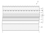
- FIG. 1 is a cross-sectional view of a decorative material including a decorative sheet according to one embodiment of the present invention.
- FIG. 2 is a cross-sectional view of a decorative material including a decorative sheet according to another embodiment of the present invention.
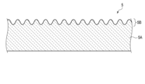
- FIG. 3 is a cross-sectional view of the surface protective layer of the decorative sheet of FIG. 1 and
- FIG. 4 is a microscope image of the surface protective layer of a decorative sheet according to one example of the present invention.
- Decorative material and decorative sheet Fig. 1 is a cross-sectional view of a decorative material including a decorative sheet according to one embodiment of the present invention.
- Fig. 2 is a cross-sectional view of a decorative material including a decorative sheet according to another embodiment of the present invention.
- Fig. 3 is a cross-sectional view of the surface protective layer of the decorative sheet of Figs. 1 and 2.
- Fig. 4 is a micrograph of the surface protective layer of a decorative sheet according to one example of the present invention.
- the cross section shown in Figure 3 is a cross section along the thickness direction of the surface protection layer.
- the micrograph in Figure 4 is a plan view taken with a laser microscope (OLS-4000, manufactured by Olympus Corporation).
- the decorative material 11 shown in Figures 1 and 2 includes a substrate B and a decorative sheet 1 attached thereto.
- the decorative material 11 is a decorative board.
- the decorative board may be a flat plate, or may be curved or folded.
- the decorative material 11 may have a shape other than a plate.
- the substrate B is a plate material.
- the plate material is, for example, a wood board, an inorganic board, a metal plate, or a composite board made of multiple materials.
- the substrate B may have a shape other than a plate.
- the decorative sheet 1 shown in FIG. 1 has a pattern layer 3 and a surface protection layer 5 provided in this order from the original fabric layer 2 side on one surface, which is the front side, of the original fabric layer 2, and a primer layer 6 provided on the other surface of the original fabric layer 2 (i.e., the surface facing the substrate B).
- a pattern layer 3 and the primer layer 6 may be omitted.
- the decorative sheet 1 shown in FIG. 2 has a pattern layer 3, an adhesive resin layer 4b, a transparent resin layer 4, and a surface protection layer 5 provided in this order from the original fabric layer 2 on one surface, i.e., the front side, of the original fabric layer 2, and a primer layer 6 provided on the other surface of the original fabric layer 2 (i.e., the surface facing the substrate B).
- the transparent resin layer 4 is provided with an embossed uneven pattern (embossed pattern 4a).
- one or more of the pattern layer 3, adhesive resin layer 4b, transparent resin layer 4, and primer layer 6 may be omitted. Also, the embossed pattern 4a does not have to be provided.
- At least one of the transparent resin layer 4 and the surface protective layer 5 may be laminated in multiple layers. Also, taking into consideration the adhesion between each layer, other known layers may be arranged. Also, a concealing layer (not shown) or the like may be provided between the base layer 2 and the primer layer 6 as appropriate.
- raw fabric layer 2 for example, any material selected from paper, synthetic resin, synthetic resin foam, rubber, nonwoven fabric, synthetic paper, metal foil, etc. can be used.
- paper include tissue paper, titanium paper, resin-impregnated paper, etc.
- synthetic resin include polyethylene, polypropylene, polybutylene, polystyrene, polycarbonate, polyester, polyamide, ethylene-vinyl acetate copolymer, polyvinyl alcohol, acrylic, etc.
- Examples of rubber include ethylene-propylene copolymer rubber, ethylene-propylene-diene copolymer rubber, styrene-butadiene copolymer rubber, styrene-isoprene-styrene block copolymer rubber, styrene-butadiene-styrene block copolymer rubber, polyurethane, etc.
- Examples of nonwoven fabric include organic and inorganic nonwoven fabrics.
- Examples of metals for the metal foil include aluminum, iron, gold, silver, etc.
- the raw fabric layer 2 may be a sheet made of the same resin composition as the transparent resin layer 4. In this case, the raw fabric layer 2 is obtained by forming a resin material or a resin composition into a film shape. Examples of the forming method include calendar molding and extrusion molding.
- the base fabric layer 2 preferably has a colored layer made of a synthetic resin mixed with an inorganic pigment, and a skin layer made of synthetic resin.
- the thickness of the skin layer is preferably 3 ⁇ m to 20 ⁇ m, and the ratio of the thickness of the skin layer to the colored layer is preferably 1:6 to 1:50.
- the outermost layer is a skin layer that does not contain pigment. It is preferable to provide a skin layer on both sides of the colored layer. If the skin layer is made thicker and its ratio to the colored layer is increased, the ratio of the colored layer will decrease, and the hiding power will decrease, which is not preferable.
- the thickness of the original fabric layer 2 is preferably 50 ⁇ m or more and 150 ⁇ m or less. If the original fabric layer 2 is less than 50 ⁇ m, the performance of covering the unevenness of the base (unevenness) decreases. On the other hand, if the thickness of the original fabric layer 2 exceeds 150 ⁇ m, there is a risk of defects such as whitening and cracks occurring during bending.
- the inorganic pigment may be a known inorganic pigment, such as titanium oxide, which is used to provide hiding properties.
- the raw cloth layer 2 plays a role in hiding the pattern of the substrate B.
- the light transmittance is preferably 40% or less. If the hiding properties are low, the pattern of the design layer 3 and the pattern of the substrate B will be mixed, which is not preferable.
- the mixed amount of the inorganic pigment is preferably 5 parts by mass or more and 50 parts by mass or less, based on 100 parts by mass of the resin material.
- the inorganic pigment contained is not particularly limited, but examples thereof include natural inorganic pigments and synthetic inorganic pigments.
- natural inorganic pigments include earth pigments, calcined earth, and mineral pigments.
- synthetic inorganic pigments include oxide pigments, hydroxide pigments, sulfide pigments, silicate pigments, phosphate pigments, carbonate pigments, metal powder pigments, carbon pigments, etc.
- synthetic inorganic pigment a mixed pigment of one or more of natural inorganic pigments and synthetic inorganic pigments may be used.
- an organic pigment such as carbon black may be used in combination.
- additives such as fatty acid metal salts may be added to inorganic pigments to improve dispersibility and extrusion suitability.
- a substrate with an inactive surface such as an olefin-based substrate
- Pattern Layer A pattern layer 3 for adding a pattern to the decorative sheet 1 can be provided on the surface of the base fabric layer 2.
- the pattern may be a wood grain pattern, a stone grain pattern, a sand grain pattern, a tiled pattern, a brickwork pattern, a cloth grain pattern, a leather-striped pattern, a geometric figure, or the like.
- a base solid ink layer (not shown) may be provided between the base layer 2 and the pattern layer 3 depending on the level of the desired design.
- the base solid ink layer is provided so as to cover the entire surface of the base layer 2.
- the base solid ink layer may also be multi-layered, with two or more layers, as necessary for hiding properties, etc.
- the pattern layer 3 may be formed by laminating as many plates as necessary to express the desired design. In this way, the pattern layer 3 and the base solid ink layer can be combined in various ways depending on the desired design, that is, the design to be expressed, but there are no particular limitations.
- the constituent materials of the base solid ink layer and the design layer 3 are not particularly limited.
- printing inks or coating agents obtained by dissolving or dispersing a matrix and a colorant such as a dye or pigment in a solvent can be used as the constituent materials of the base solid ink layer and the design layer 3.
- a colorant such as a dye or pigment in a solvent
- various synthetic resins such as oil-based nitrocellulose resin, two-liquid urethane resin, acrylic resin, styrene resin, polyester resin, urethane resin, polyvinyl resin, alkyd resin, epoxy resin, melamine resin, fluorine resin, silicone resin, and rubber resin, or mixtures or copolymers thereof can be used.
- inorganic pigments such as carbon black, titanium white, zinc oxide, red oxide, yellow lead, Prussian blue, and cadmium red
- organic pigments such as azo pigments, lake pigments, anthraquinone pigments, phthalocyanine pigments, isoindolinone pigments, and dioxazine pigments, or mixtures thereof can be used.
- toluene, xylene, ethyl acetate, butyl acetate, methyl alcohol, ethyl alcohol, isopropyl alcohol, acetone, methyl ethyl ketone, methyl isobutyl ketone, cyclohexanone, water, etc., or mixtures thereof, etc. can be used.
- functional additives such as extender pigments, plasticizers, dispersants, surfactants, tackifiers, adhesive aids, drying agents, hardeners, hardening accelerators, and hardening retarders may be added to the base solid ink layer and the pattern layer 3 to impart various functions.
- the base solid ink layer and the design layer 3 can be formed by various printing methods such as gravure printing, offset printing, screen printing, electrostatic printing, and inkjet printing.
- the base solid ink layer covers the entire surface of the base layer 2, it can also be formed by various coating methods such as roll coating, knife coating, microgravure coating, and die coating. These printing and coating methods may be selected separately depending on the layer to be formed, but it is more efficient to select the same method and process them all at once.
- the thickness of the pattern layer 3 is preferably 3 ⁇ m or more and 20 ⁇ m or less. When the thickness of the pattern layer 3 is within this range, the printing can be made clear, the printing workability when manufacturing the decorative sheet 1 is improved, and manufacturing costs can be reduced.
- the resin material used as the main component of the transparent resin layer 4 is preferably made of an olefin-based resin, and in addition to polypropylene, polyethylene, polybutene, etc., ⁇ -olefins (e.g., propylene, 1-butene, 1-pentene, 1-hexene, 1-heptene, 1-octene, 1-nonene, 1-decene, 1-undecene, 1-dodecene, tridecene, 1-tetradecene, 1-pentadecene, 1-hexadecene, 1-heptadecene, 1-octadecene, 1-nonadecene, 1-eicosene, 3-methyl-1-butene, 3-methyl-1-pentene, 3-ethyl-1-pentene, 4-methyl-1-pentene, 4-methyl-1-hexene, 4,4-dimethyl-1-pent ...
- copolymers examples include those obtained by homopolymerizing or copolymerizing two or more of ⁇ -olefins (such as ethylene-vinyl acetate copolymer, ethylene-vinyl alcohol copolymer, ethylene-methyl methacrylate copolymer, ethylene-ethyl methacrylate copolymer, ethylene-butyl methacrylate copolymer, ethylene-methyl acrylate copolymer, ethylene-ethyl acrylate copolymer, ethylene-butyl acrylate copolymer, etc.) with ethylene or an ⁇ -olefin and a monomer other than ⁇ -olefin.
- ⁇ -olefins such as ethylene-vinyl acetate copolymer, ethylene-vinyl alcohol copolymer, ethylene-methyl methacrylate copolymer, ethylene-ethyl methacrylate copolymer, ethylene-butyl methacrylate cop
- main component refers to 90% or more by mass of the target material.
- the thickness of the transparent resin layer 4 is preferably 50 ⁇ m or more and 100 ⁇ m or less. If it is less than 50 ⁇ m, the effect of improving the scratch resistance of the surface of the transparent resin layer 4 is low, and there is little point in providing the transparent resin layer 4. If the thickness of the transparent resin layer 4 exceeds 100 ⁇ m, the rigidity of the decorative sheet 1 is too high, and there is a risk of problems such as whitening and cracking occurring during bending.
- the thickness of the transparent resin layer 4 may be less than 50 ⁇ m.
- the resin composition constituting the transparent resin layer 4 may contain various functional additives such as heat stabilizers, light stabilizers, ultraviolet absorbers, antiblocking agents, catalyst scatterers, colorants, light scattering agents, and gloss adjusters, as necessary. These various functional additives can be appropriately selected from well-known additives.
- the adhesive used to bond the pattern layer 3 and the transparent resin layer 4 can be any material selected depending on the bonding method.
- bonding methods include lamination methods using heat lamination, extrusion lamination, dry lamination, etc., and the adhesive can be selected from acrylic, polyester, polyurethane, etc. Due to its cohesive strength, a two-liquid curing type urethane material that utilizes the reaction between isocyanate and polyol is usually desirable.
- lamination method for the transparent resin layer 4 but methods using heat and pressure, extrusion lamination, dry lamination, etc. are commonly used.
- the transparent resin layer 4 may also be provided with an embossed pattern (embossed pattern 4a).
- Ink can be embedded in the embossed pattern 4a to further improve the design.
- the embossed pattern 4a can be provided by a method in which a sheet that has been laminated using various methods is first embossed using heat and pressure, or by providing a pattern on a cooling roll and embossing the sheet at the same time as extrusion lamination.
- embossed pattern layer 3 and the transparent resin layer 4 are bonded together by heat or dry lamination at the same time as extrusion.
- an adhesive resin layer 4b may be provided between the pattern layer 3 and the transparent resin layer 4.
- an adhesive resin layer 4b may be provided between the transparent resin layer 4 and the adhesive.
- lamination can be performed by co-extrusion of the transparent resin layer 4 and the adhesive resin layer 4b.
- the adhesive resin layer 4b can be an acid-modified resin such as polypropylene, polyethylene, or acrylic resin.
- the thickness of the adhesive resin layer 4b is desirably 2 ⁇ m or more in order to improve adhesion.
- the uneven structure can be expressed by the cut level difference Rdc.
- the "cut level difference Rdc” is a surface property parameter defined in JIS B0601:2013.
- the cut level difference Rdc indicates the cut level difference of the roughness curve and expresses the steepness of the uneven shape.
- the position of the highest peak of the roughness curve is the reference for the cut level c.
- c (Rmr1) is the cut level when the load length ratio Rmr of the roughness curve is 10%
- c (Rmr2) is the cut level when the load length ratio Rmr of the roughness curve is 25%.
- the cut level difference Rdc ( ⁇ m) of the roughness curve is the difference between the cut level c (Rmr1) and the cut level c (Rmr2).
- the Rdc of the transparent resin layer 4 is preferably 0.2 ⁇ m or more and 2.9 ⁇ m or less. If the Rdc is less than 0.2 ⁇ m, the effect of embedding the ink is weakened, and if it is more than 2.9 ⁇ m, when the surface protection layer 5 is formed on the transparent resin layer 4, the touch becomes rougher than the moist touch of the present invention, which is not preferable.
- the Rdc of the transparent resin layer 4 is preferably 0.2 ⁇ m or more and 1.0 ⁇ m or less.
- the surface protection layer 5 has a core portion 5A and a ridge portion 5B that protrudes in a ridge shape from one surface of the core portion 5A. This forms an uneven shape in the surface protection layer 5.
- the "ridge shape” refers to a shape that is elongated and raised and linearly connected in a plan view.
- the ridge portion 5B may be curved or linear in a plan view, but is preferably curved from the viewpoint of the fingerprint resistance of the decorative sheet 1.
- the ridge portion 5B refers to, for example, the portion from the lowest part to the highest part of the uneven shape of the surface protection layer 5
- the core portion 5A refers to the portion of the surface protection layer 5 excluding the ridge portion 5B.
- the cross-sectional shape of the ridge portion 5B in the thickness direction of the surface protection layer 5 may be a sine wave shape.
- the sine wave shape referred to here means a shape in which the line extending from the lowest point to the highest point of the ridge portion 5B can be expressed as a sine wave.
- Fig. 3 is a cross-sectional view showing a schematic cross-section of the ridge portion 5B of the surface protective layer 5 (cross-section in the thickness direction of the surface protective layer 5), and Fig. 4 is a planar photograph showing the surface structure of the surface protective layer 5.
- Fig. 4 is a planar photograph obtained using a laser microscope (OLS-4000, manufactured by Olympus Corporation).
- the ridged portion 5B is elongated and raised, and is connected linearly in plan view. As described below, the ridged portion 5B is formed by irradiating the surface of the ionizing radiation curable resin with light of a specific wavelength, causing the cured film of the ionizing radiation curable resin to buckle.
- the shape of such ridged portion 5B can be expressed by the ratio RSm/Ra of the surface roughness index RSm ( ⁇ m) in the horizontal direction (the planar direction of surface protective layer 5, the left-right direction in FIG. 3) to the surface roughness index Ra ( ⁇ m) in the vertical direction (the depth direction of ridged portion 5B, the thickness direction of transparent molding layer 5, the up-down direction in FIG. 3).
- the ratio RSm/Ra is preferably 10 or more and 300 or less. More preferably, RSm/Ra is 10 or more and 250 or less.
- the surface roughness indices Ra and RSm are measured using a line roughness gauge and are measurements made in accordance with JIS B0601.
- the uneven structure of the surface protective layer 5 has a ratio Rdc/t (hereinafter simply referred to as "ratio Rdc/t") of the cut level difference Rdc to the thickness t of the surface protective layer 5 of 0.15 to 0.44.
- the ratio Rdc/t is preferably 0.15 to 0.31, and more preferably 0.15 to 0.25.
- the "cut level difference Rdc” is a surface property parameter defined in JIS B0601:2013.
- the cut level difference Rdc indicates the cut level difference of the roughness curve and expresses the steepness of the uneven shape.
- the position of the highest peak of the roughness curve is the reference for the cut level c.
- c (Rmr1) is the cut level when the load length ratio Rmr of the roughness curve is 10%
- c (Rmr2) is the cut level when the load length ratio Rmr of the roughness curve is 25%.
- the cut level difference Rdc ( ⁇ m) of the roughness curve is the difference between the cut level c (Rmr1) and the cut level c (Rmr2).
- the ratio Rdc/t is obtained by dividing the cut level difference Rdc by the thickness t of the surface protective layer 5, and the steepness of the uneven shape per unit thickness of the surface protective layer 5 can be expressed.
- the region of the surface of the surface protective layer corresponding to the portion where the load length ratio Rmr of the roughness curve is less than 10% is the region where the fingertip first comes into contact when the surface protective layer is pressed with the fingertip.
- the moist tactile sensation is not greatly influenced by the region of the surface of the surface protective layer where the fingertip first comes into contact when the pressure applied from the fingertip to the surface protective layer is extremely large.
- the moist tactile sensation is greatly influenced by the slope of the region of the surface of the surface protective layer where the fingertip first comes into contact when the pressure applied from the fingertip to the surface protective layer is increased to a certain degree.
- This region corresponds to the region where the load length ratio Rmr of the roughness curve is in the range of 10% to 25%.
- the slope of the uneven shape is relatively gentle.
- the resistance to pressure caused by contact between the finger and the surface is small, and the contact area between the finger and the convex surface gradually increases, resulting in a tactile sensation as if the surface of the decorative sheet is sticking to the finger.
- This tactile sensation can be associated with a "moist tactile sensation.”
- the slope of the uneven shape is quite gentle.
- the surface of the decorative sheet when the surface of the decorative sheet is pressed with a finger and slid across the surface with the finger, the pressing resistance due to contact between the finger and the surface is small, the contact area between the finger and the convex surface is large from the start of the pressing action, and the increase in this contact area accompanying the pressing action is quite gradual.
- the surface of the decorative sheet feels as if it is sticking to the finger, while, because the slope of the uneven shape is quite gentle, a smooth feel is obtained compared to the "moist feel" mentioned above, and the overall impression of a smooth feel is stronger. This feel can be associated with a "smooth feel.”
- the thickness t of the surface protective layer 5 is 2 ⁇ m or more and 18 ⁇ m or less.
- the thickness t of the surface protective layer 5 is preferably 3 ⁇ m or more and 10 ⁇ m or less.
- the surface protective layer 5 is too thick or too thin, it becomes difficult to achieve a "moist touch." Furthermore, when the surface protective layer 5 is made thin, it becomes difficult to achieve a low glossiness, and when it is made thicker, the processability decreases and whitening occurs when bending.
- the thickness of the surface protective layer 5 is the thickness of a layer that has the same apparent area and volume as the surface protective layer 5 and has a flat surface.
- the thickness of the surface protective layer 5 is determined, for example, by the following method. First, a cross section parallel to the thickness direction of the surface protective layer 5 and perpendicular to the length direction of the ridge portion 5B is imaged. Next, from this cross-sectional image, the dimension of the surface protective layer 5 in the width direction of the ridge portion 5B and the area of the cross section of the surface protective layer 5 are determined. The thickness of the surface protective layer 5 is a value obtained by dividing this area by the above dimension. The thickness of the surface protective layer 5 is determined by observing the cross section with a scanning electron microscope and averaging 25 points.
- the thickness of the surface protective layer 5 can be determined as described in the examples described later. Note that when the coating liquid for the surface protective layer described later does not contain a solvent, the thickness of the coating film made of the coating liquid for the surface protective layer is equal to the thickness of the surface protective layer 5.
- the surface protective layer 5 can be formed by various printing methods such as gravure printing, offset printing, screen printing, electrostatic printing, inkjet printing, etc.
- the surface protective layer 5 covers the entire surface of the front side of the raw fabric layer 2, it can also be formed by various coating methods such as roll coating, knife coating, microgravure coating, die coating, etc. These printing or coating methods may be selected separately depending on the layer to be formed, or the same method may be selected and processed all at once.
- the pattern layer 3 and the surface protective layer 5 may be synchronized from the viewpoint of design. In such a case, it is necessary to form the surface protective layer 5 all at once after forming the pattern layer 3, so it is preferable to use a gravure printing method. In addition, the gravure printing method allows for relatively high speed processing, which is advantageous in terms of cost and is preferable.
- synchronization means that 50% or more, preferably 70% or more, and most preferably 90% or more of the portion where the surface protective layer 5 is formed overlaps with the pattern portion of the pattern layer 3 in a planar view.
- the thickness of the surface protective layer 5 can be adjusted by adjusting the amount of coating in the printing and coating methods described above.
- the amount of coating can be calculated from the mass difference between a base sheet (including the base layer) with the surface protective layer 5 formed and one without it, produced using various printing and coating methods.
- the main material of the surface protective layer 5 is preferably an ionizing radiation curable resin.
- the main material means that the main material contains 60 parts by mass or more, more preferably 70 parts by mass or more, and most preferably 80 parts by mass or more per 100 parts by mass of the surface protective layer 5.
- ionizing radiation refers to a charged particle beam such as an electron beam.
- the ionizing radiation curable resin is cured by irradiation with ionizing radiation.
- the ionizing radiation curable resin can also be cured by ultraviolet irradiation.
- the ionizing radiation curable resin used here is cured by irradiation with light having a wavelength of 200 nm or less, and has a large absorption coefficient for this light.
- the ionizing radiation curable resin constituting the surface protective layer 5 known materials such as various monomers and commercially available oligomers can be used, for example, (meth)acrylic resins, silicone resins, polyester resins, urethane resins, amide resins, and epoxy resins can be used.
- the ionizing radiation curable resin may be either an aqueous resin or a non-aqueous (organic solvent-based) resin, and may be used alone or in combination of multiple types.
- the main component of the ionizing radiation curable resin is preferably an acrylate.
- the main component of the ionizing radiation curable resin means a component that accounts for 60% by mass or more of the ionizing radiation curable resin.
- the ionizing radiation curable resin preferably contains 70 parts by mass or more of acrylate, and more preferably contains 80 parts by mass or more.
- the acrylate is preferably an acrylate having two or more functional groups, and more preferably an acrylate having three or more functional groups.
- the acrylate is preferably an acrylate having three or more functional groups. There is no upper limit to the number of functional groups of the acrylate, but in one example, it is six or less functional groups.
- the acrylate preferably contains a repeating structure.
- This repeating structure is, for example, any one of an ethylene oxide (EO) structure, a propylene oxide (PO) structure, and an ⁇ -caprolactone (CL) structure.
- the repeating structure is preferably ethylene oxide or propylene oxide.
- the repeating structure may be present between the acryloyl group and the methylol group in an open ring state.
- the number of repetitions of the repeating structure is preferably 3 or more. If an acrylate with a large number of repetitions is used, the cured film is more likely to expand in the in-plane direction in the first irradiation step described below, and therefore wrinkles corresponding to the ridged portions 5B are more likely to appear on the coating film surface. In addition, if an acrylate with a large number of repetitions is used, there is a tendency for the ratio Rdc/t to be larger. However, if the number of repetitions is increased, the crosslink density decreases, and the scratch resistance of the surface protective layer decreases.
- the ionizing radiation curable resin is a trifunctional acrylate containing a repeating structure.
- EO-modified, PO-modified, or CL-modified trimethylolpropane triacrylate, glycerin triacrylate, isocyanurate triacrylate, or pentaerythritol triacrylate can be used as the trifunctional acrylate containing a repeating structure.
- the optimum viscosity range of the ionizing radiation curable resin is 10 to 500 mPa ⁇ s.
- trimethylolpropane triacrylate or glycerin triacrylate as the trifunctional acrylate resin, since it is possible to keep the viscosity within the optimum range.
- Resins having a skeleton that causes hydrogen bonding or ⁇ - ⁇ stacking often have a high viscosity of 500 mPa ⁇ s or more, which is not preferable.
- organic solvents or low-viscosity bifunctional acrylate resins can be added to adjust the viscosity. However, it is preferable not to use organic solvents from the viewpoint of environmental load. If a large amount of bifunctional acrylate resin is added, scratch resistance decreases, which is not preferable. Therefore, the amount of bifunctional acrylate resin added is preferably within the range of 10% by mass to 30% by mass of the content (mass) of the trifunctional acrylate resin.
- the number of repetitions of the repeating structure is preferably 3 or more, more preferably 3 to 30, and even more preferably 3 to 20. If the number of repetitions is small, the cured film of the ionizing radiation curable resin that constitutes the surface protective layer 5 is less likely to swell in the in-plane direction when irradiated with vacuum ultraviolet light (VUV light), and therefore wrinkles are not sufficiently formed, making it difficult for the surface protective layer 5 to have a low gloss. If the number of repetitions is large, the crosslinking density decreases, and the scratch resistance of the surface protective layer 5 tends to decrease.
- VUV light vacuum ultraviolet light
- the ionizing radiation curable resin is a tetrafunctional acrylate containing a repeating structure.
- EO-modified, PO-modified, or CL-modified pentaerythritol tetraacrylate can be used as the tetrafunctional acrylate containing a repeating structure.
- the number of repeats of the repeating structure is preferably 12 or more, more preferably 12 to 50, even more preferably 20 to 50, and even more preferably 20 to 35.
- the number of repeats is small, when irradiated with VUV light, the cured film of the ionizing radiation curable resin constituting the surface protective layer 5 is unlikely to swell in the in-plane direction, and therefore wrinkles are not sufficiently formed, making it difficult for the surface protective layer 5 to have a low gloss. If the number of repeats is large, the crosslinking density decreases, and the scratch resistance of the surface protective layer 5 tends to decrease.
- the number of repetitions of the repeating structure can be analyzed by using MALDI-TOF-MS.
- the ionizing radiation curable resin may have a molecular weight distribution. When the molecular weight distribution is present, the number of repetitions is set to the number of repetitions corresponding to the molecular weight having the strongest peak in the mass spectrum of MALDI-TOF-MS.
- the number of repetitions of the repeating structure may be calculated based on the ratio I 1095 /I 1725 calculated by Fourier infrared spectrometry, as described below.
- the ratio I 1095 /I 1725 between the maximum value I 1095 in the wave number range of 1085 to 1105 cm -1 and the maximum value I 1725 in the wave number range of 1715 to 1735 cm -1 is 0.65 or more. If the ratio I 1095 /I 1725 value is less than 0.65, the number of repetitions is small, so that when irradiated with VUV light, the cured film of the ionizing radiation curable resin constituting the surface protective layer 5 is unlikely to swell in the in-plane direction, and therefore wrinkles are not sufficiently formed, and the surface protective layer 5 does not have a low gloss.
- the ratio I 1095 /I 1725 value is preferably 0.7 or more, more preferably 0.85 or more.
- the ratio I 1095 /I 1725 is desirably 3.5 or less.
- the ratio I 1095 /I 1725 is more preferably 2.2 or less, and even more preferably 1.3 or less.
- Infrared light with wavelengths in the range of 2.5 to 25 ⁇ m can change the vibrational and rotational states of molecules.
- the energy required to change the vibrational and rotational states varies depending on the structure of the molecule.
- Infrared spectroscopy is a measurement method that utilizes this to obtain information about the chemical structure and state of a substance.
- measurements are performed as follows. First, light from a light source is incident on a semi-transparent mirror at an angle and split into two beams of light: transmitted light and reflected light. The beam that passes through the semi-transparent mirror is reflected by a fixed mirror and re-enters the semi-transparent mirror at an angle. The beam reflected by the semi-transparent mirror is reflected by a movable mirror and re-enters the semi-transparent mirror at an angle. The beam reflected from the fixed mirror and reflected by the semi-transparent mirror and transmitted through the semi-transparent mirror are combined to generate an interference wave.
- this interference wave is irradiated onto the sample and the intensity of the light that passes through the sample is measured.
- the intensity data obtained in this way is separated by calculation into the intensities of each wave number component (Fourier transform) to obtain a transmittance spectrum.
- the reflected light intensity is measured using the total reflectance method (ATR method) described below.
- the interference wave is incident on a measurement prism that is in contact with the surface of the sample.
- the interference wave is incident on the measurement prism so that it is totally reflected at the interface between the prism and the sample.
- evanescent waves seep into the area of the sample near the interface, and light of a specific wavenumber component is absorbed by molecules in this area.
- the intensity of reflected light is measured. The intensity data obtained in this way is then separated by calculation into the intensities of each wavenumber component (Fourier transform) to obtain the ATR spectrum.
- the penetration depth (depth of penetration) of evanescent waves increases as the wavelength becomes longer. Therefore, the baseline of an ATR spectrum, with the horizontal axis representing wavelength and the vertical axis representing reflected light intensity (or reflectance), slopes downward to the right.
- the penetration depth of evanescent waves is also affected by the angle of incidence of the interference wave at the interface and the refractive index of the prism and sample. Therefore, the ATR spectrum is corrected by the inverse of the wavelength, etc. By performing such correction, a spectrum with a peak intensity ratio similar to that of the transmittance spectrum can be obtained. Then, by converting this spectrum, an absorption spectrum can be obtained with the horizontal axis representing wavenumber and the vertical axis representing absorbance.
- the penetration depth of the evanescent wave is small, and can be adjusted by the angle of incidence of the interference wave and the refractive index of the prism. Therefore, Fourier transform infrared spectroscopy using the ATR method can prevent the underlying layer from becoming noise, even if the object to be measured is a thin layer. Furthermore, Fourier transform infrared spectroscopy using the ATR method allows non-destructive measurement as long as the object to be measured is exposed on the surface of the sample.
- the absorption spectrum obtained by Fourier infrared spectroscopy of the surface protective layer 5 has a ratio I 1095 /I 1725 within a predetermined range.
- the maximum value I 1095 in the wave number range of 1085 to 1105 cm -1 is a value related to the number of ether bonds contained in the surface protective layer 5.
- the maximum value I 1725 in the wave number range of 1715 to 1735 cm -1 is a value related to the number of ester bonds. Therefore, the ratio I 1095 /I 1725 corresponds to the ratio between the number of ether bonds and the number of functional groups of the acrylate contained in the ionizing radioactive resin of the coating liquid for surface protective layer described below.
- the surface protection layer 5 may contain particles. By adding particles of an optimal particle size and optimal content, a uniform surface can be formed.
- organic materials such as polyethylene (PE) wax, polypropylene (PP) wax, and resin beads, or inorganic materials such as silica, glass, alumina, titania, zirconia, calcium carbonate, and barium sulfate can be used as particles.
- the average particle size (D50) of the particles is preferably 3 ⁇ m or more and 11 ⁇ m or less, and more preferably 4 ⁇ m or more and 10 ⁇ m or less.
- the surface protective layer 5 contains particles, wrinkles can be more uniformly generated on the coating surface in the first irradiation step described below.
- the average particle size (D50) of the particles increases, the value of the ratio Rdc/t tends to decrease. For this reason, if the average particle size (D50) is too small or too large, it becomes difficult to achieve a "moist tactile feel.” Furthermore, when large particles are used, the particles are likely to fall off from the surface protective layer 5, making it difficult to achieve high scratch resistance. Small particles are less effective at generating uniform wrinkles.
- the "average particle size (D50)" is the median size (D50) measured by a laser diffraction/scattering type particle size distribution measuring device. If the coating liquid for the surface protective layer contains particles, the surface protective layer 5 obtained from this coating liquid will also contain particles. The average particle size of the particles contained in the surface protective layer 5 can be determined by observing the cross section of the layer and averaging the particle sizes of multiple particles. The value obtained in this manner is substantially the same as the median size (D50) measured by a laser diffraction/scattering type particle size distribution measuring device. Therefore, the above-mentioned range of average particle sizes can also be interpreted as the range of average particle sizes of the particles contained in the surface protective layer 5.
- the particles are preferably contained in the surface protection layer 5 in an amount of 3 to 11 parts by weight per 100 parts by weight of the ionizing radiation curable resin. It is more preferable that the amount of particles added is 4 to 10 parts by weight per 100 parts by weight of the resin. Note that "100 parts by weight of resin” refers to the parts by weight of the solid content of the resin.
- the effect of creating uniform wrinkles is particularly large.
- the value of the ratio Rdc/t tends to decrease.
- the amount of particles added is too little or too much, it becomes difficult to achieve a "moist feel."
- the particles are likely to fall off from the surface protective layer 5, making it difficult to achieve high scratch resistance. If a small amount of particles is added, the effect of creating uniform wrinkles is small.
- photopolymerization initiator there are no particular limitations on the photopolymerization initiator, but examples include benzaphenone-based, acetophenone-based, benzoin ether-based, and thioxanthone-based initiators.
- the surface protective layer 5 may further contain additives such as antibacterial agents and antifungal agents to impart the required functions.
- additives such as antibacterial agents and antifungal agents to impart the required functions.
- it may further contain ultraviolet absorbers and light stabilizers as necessary. It is common to add any combination of ultraviolet absorbers such as benzotriazoles, benzoates, benzophenones, and triazines, and light stabilizers such as hindered amines.
- Hindered amine light stabilizers that can be used include, for example, bis(1,2,2,6,6-pentamethyl-4-piperidyl)[[3,5-bis(1,1-dimethylethyl)-4-hydroxyphenyl]methyl]butyl malonate (a representative example is BASF's product name "Tinuvin 144"), BASF's product name "Tinuvin 123”, and the reaction product of decanedioic acid bis(2,2,6,6-tetramethyl-1-(octyloxy)-4-piperidinyl) ester (1,1-dimethylethyl hydroperoxide) and octane.
- the hindered amine light stabilizer When the hindered amine light stabilizer is added to the surface protective layer 5, it is preferable to add it in the range of 0.05 parts by mass to 5 parts by mass to 100 parts by mass of the ionizing radiation curable resin.
- the amount of the hindered amine light stabilizer added is more preferably in the range of 0.2 parts by mass to 3 parts by mass. If the amount of the hindered amine light stabilizer added is less than 0.05 parts by mass, the effect of stabilizing the resin against ultraviolet rays may be low. On the other hand, if it is more than 5 parts by mass, there is a high possibility that bleed-out may occur.
- the surface protective layer 5 can be formed by irradiating light of 200 nm or less to cure and shrink the vicinity of the surface to form a fine uneven shape.
- the hindered amine light stabilizer is contained in an amount of more than 3 parts by mass, it may inhibit the curing of the vicinity of the surface.
- the glossiness of the surface protective layer 5 is preferably less than 10.0. It is more preferable that the glossiness of the surface protective layer 5 is 5.0 or less.
- glossiness is the measured value when measured at an incidence angle of 60 degrees using a glossmeter conforming to JIS Z8741:1997.
- Primer layer 6 can be made of the same material as the pattern layer 3. Considering that the primer layer 6 is applied to the back surface of the decorative sheet 1 and is wound in a web form, inorganic fillers such as silica, alumina, magnesia, titanium oxide, barium sulfate, etc. may be added to avoid blocking and improve adhesion with the adhesive.
- the coating thickness of the primer layer 6 is preferably 0.1 ⁇ m or more and 3.0 ⁇ m or less, since the purpose is to ensure adhesion with the substrate B.
- the primer layer 6 is necessary when the surface of the raw fabric layer 2 is inactive, such as an olefin-based material, but is not particularly necessary when the surface is active.
- the decorative sheet 1 is manufactured, for example, by the following method.
- explanations regarding the design layer 3, transparent resin layer 4, adhesive resin layer 4b, and primer layer 6 are omitted here.
- a coating film made of a coating liquid for the surface protective layer is formed on one surface of the base layer 2.
- the coating liquid for the surface protective layer contains an ionizing radiation curable resin, and, if necessary, particles and additives.
- the coating film made of the coating liquid for the surface protective layer can be formed, for example, by printing.
- the first irradiation step is carried out.
- the coating film is irradiated with light having a wavelength of 200 nm or less (hereinafter referred to as the first radiation).
- the ionizing radiation curable resin contained in the coating liquid for the surface protective layer has a large absorption coefficient for the first radiation. Therefore, the first radiation incident on the coating film can only reach a position several tens to several hundreds of nm away from the outermost surface. Therefore, in the first irradiation step, the crosslinking reaction proceeds in the surface region of the coating film to form an extremely thin cured film, while in other regions, the crosslinking reaction does not proceed and the coating film remains uncured.
- the coating film After the first irradiation process, the coating film has wrinkles on its surface that correspond to the ridged portion 5B.
- the inventor believes that the reason wrinkles form on the coating film surface as a result of the first irradiation process is as follows.
- the first radiation can only reach a position that is tens to hundreds of nanometers away from the outermost surface of the coating film.
- the crosslinking reaction of the ionizing radiation curable resin occurs only on the surface of the coating film, and areas that are more than tens to hundreds of nanometers away from the outermost surface are uncured and contain highly fluid molecules. These highly fluid molecules swell the cured film, thereby increasing its volume. The increase in volume in the in-plane direction causes the cured film to buckle, resulting in wrinkles on the surface of the coating film.
- the first radiation can be extracted from excimer VUV light.
- Excimer VUV light can be produced from a lamp that uses a rare gas or a rare gas halide compound.
- a lamp that contains a rare gas or a rare gas halide compound gas When high-energy electrons are provided from the outside to a lamp that contains a rare gas or a rare gas halide compound gas, a large number of discharge plasmas (dielectric barrier discharges) are generated. This plasma discharge excites the atoms of the discharge gas (rare gas), which momentarily enters an excimer state. When returning from this excimer state to the ground state, light is emitted in a wavelength range specific to that excimer.
- the gas used in the excimer lamp may be any conventional gas that emits light of 200 nm or less.
- the gas may be a rare gas such as Xe, Ar, or Kr, or a mixture of a rare gas such as ArBr or ArF with a halogen gas.
- the central wavelength of the excimer lamp varies depending on the gas, and may be, for example, about 172 nm (Xe), about 126 nm (Ar), about 146 nm (Kr), about 165 nm (ArBr), or about 193 nm (ArF).
- a xenon lamp that emits excimer light with a central wavelength of 172 nm as the light source. Also, considering the cost of maintaining the equipment and the availability of materials, it is preferable to use a xenon lamp as the light source.
- the first irradiation step is carried out in an atmosphere with a low oxygen concentration.
- Oxygen has a large absorption coefficient for light of 200 nm or less. Therefore, the first irradiation step is preferably carried out in, for example, a nitrogen gas atmosphere.
- the oxygen concentration in the gas phase in the first irradiation step i.e., the residual oxygen concentration in the reaction atmosphere, is preferably 2000 ppm or less, and more preferably 1000 ppm or less.
- oxygen in the atmosphere inhibits radical polymerization. Therefore, the residual oxygen concentration in the reaction atmosphere affects the formation of wrinkles on the coating surface. Therefore, changing the residual oxygen concentration in the reaction atmosphere can also change the surface properties of the surface protective layer 5.
- the integrated light amount of the first radiation is preferably 0.5 mJ/ cm2 to 200 mJ/cm2, more preferably 1 mJ/cm2 to 100 mJ/ cm2 , even more preferably 3 mJ/cm2 to 50 mJ/ cm2 , and most preferably 5 mJ/ cm2 to 30 mJ/ cm2 . If the integrated light amount is reduced, the cured film expands less in the in-plane direction. If the integrated light amount is increased, the surface condition of the coating film deteriorates.
- the second irradiation step is carried out.
- the coating film is irradiated with a second radiation to harden the entire coating film. This results in the surface protection layer 5.
- the second radiation is ionizing radiation such as an electron beam, or ultraviolet light having a longer wavelength than the first radiation.
- ultraviolet light When ultraviolet light is used as the second radiation, the ultraviolet light has a wavelength at which the ionizing radiation curable resin exhibits a small absorption coefficient.
- the accumulated light amount of the second radiation is preferably 10 mJ/ cm2 or more and 500 mJ/ cm2 or less, more preferably 50 mJ/cm2 or more and 400 mJ/ cm2 or less, and even more preferably 100 mJ/ cm2 or more and 300 mJ/ cm2 or less.
- the decorative sheet 1 can be manufactured by, for example, the above-mentioned method.
- the decorative sheet 1 may also be manufactured by other methods. For example, a plate may be formed using the method described above for the surface protective layer 5, and the surface protective layer 5 having a concave-convex structure on its surface may be formed by transfer using this plate.
- the decorative sheet 1 described with reference to Figures 1 to 4 has the surface properties of the surface protective layer 5 described above.
- Such a decorative sheet 1 gives the user a moist tactile sensation when the user slides a finger over the surface while pressing the surface of the surface protective layer 5 with the skin, for example, when the user slides a finger over the surface while pressing the surface of the surface protective layer 5 with the finger. That is, since the slope of the uneven shape on the surface of the surface protective layer 5 of this decorative sheet 1 is relatively gentle, when the user touches the surface by the above action, the contact area between the finger and the convex surface can be gradually increased while keeping the pressing resistance caused by the contact between the finger and the surface small. This gives a tactile sensation of the surface of the decorative sheet sticking to the finger.
- the moist feel gives a sense of comfort and warmth to those who touch the decorative sheet 1.
- the moist feel also gives the decorative sheet 1 a sense of luxury. Therefore, the decorative sheet 1 that gives the user a moist feel is suitable for use in applications where the user's skin comes into contact with it frequently or where the user's skin comes into contact with it for long periods of time, such as table tops, chair armrests, handrails on stairs or in corridors, etc.
- the surface protective layer 5 of the decorative sheet 1 has the above-mentioned surface properties, and therefore can achieve a low gloss even without the inclusion of a gloss regulator (matt additive).
- the gloss regulator reduces the oil repellency of the layer formed from the resin material, so the surface protective layer 5 containing the gloss regulator is prone to fingerprints.
- the surface protective layer 5 without the gloss regulator is less likely to absorb oil, so fingerprints are less likely to adhere to it.
- the surface protective layer 5 with excellent oil repellency is less likely to cause oil stains or adsorb contaminants.
- the surface protective layer 5 without the gloss regulator does not lose the particles of the gloss regulator when its surface is scratched, and therefore the decorative sheet 1 containing such a surface protective layer 5 is less likely to cause gloss changes or scratches.
- the decorative sheet 1 is excellent in fingerprint resistance, contamination resistance, and scratch resistance, as well as weather resistance and processability.
- Oxygen in the gas phase not only absorbs short-wavelength ultraviolet light, but also inhibits radical polymerization.
- the effect of oxygen contained in the gas phase on radical polymerization is greatest in the portion of the coating film made of ionizing radiation curable resin adjacent to the gas phase, and decreases as the distance from the coating film surface increases. Therefore, by changing the oxygen concentration in the gas phase in the first irradiation step, it is possible to change the relationship between the distance from the coating film surface and the progress of the crosslinking reaction.
- the thickness of the cured film formed on the surface of the coating by the first irradiation process and the degree of expansion of the cured film in the in-plane direction according to the progress of the crosslinking reaction change.
- the integrated light amount in the first irradiation process also affects the thickness of the cured film and the degree of expansion of the cured film in the in-plane direction.
- the thickness of the cured film and the degree of expansion of the cured film in the in-plane direction also affect the surface properties of the surface protective layer.
- the particle size and amount of particles added in the coating film, as well as the thickness of the coating film also affect the formation of wrinkles.
- Example 1 An olefin film (manufactured by RIKEN TECHNOS CORPORATION) having a thickness of 55 ⁇ m was used as the original layer 2, one side of the original layer 2 was subjected to corona treatment, and the other side was subjected to pattern printing to form a pattern layer 3.
- the pattern layer 3 was formed using a two-liquid urethane ink (V180; manufactured by Toyo Ink Co., Ltd.) to which 0.5 parts by mass of a hindered amine-based light stabilizer (Chimasorb 944; manufactured by BASF) was added relative to the binder resin content of the ink.
- the cut level difference Rdc of the surface of the pattern layer 3 was 0.4 ⁇ m.
- the cut level difference Rdc was measured using a surface roughness meter (manufactured by Mitutoyo Corporation, SJ-310) under the measurement conditions of a cutoff value ⁇ c of 2.5 mm, a cutoff value ⁇ s of 8 ⁇ m, and an evaluation length of 12.5 mm. Measurements were performed at any five points along a direction perpendicular to the film formation direction, and the average value was taken as the measured value.
- a primer layer 6 was formed on the back surface of the base layer 2.
- the primer layer 6 was formed by printing with the same two-component urethane ink as the design layer 3.
- the coating liquid for a surface protective layer was applied onto the design layer 3.
- the thickness of the coating liquid for a surface protective layer was 5 ⁇ m.
- the coating liquid for a surface protective layer was a mixture of the following ionizing radiation curable resin and the following additives (particles, photopolymerization initiator).
- the first irradiation step was carried out. Specifically, under atmospheric pressure and in a nitrogen gas atmosphere with an oxygen concentration of 100 ppm, the surface of the coating film made of the coating liquid for surface protection layer was irradiated with ultraviolet light having a wavelength of 172 nm using a Xe excimer lamp so that the cumulative light amount was 30 mJ/ cm2 . This caused wrinkles to form on the surface of the coating film.
- a second irradiation step was carried out. Specifically, the coating film was irradiated with ultraviolet light using a high-pressure mercury lamp at 200 mJ/cm 2 to cure the entire coating film, thereby forming a surface protective layer 5. In this manner, a decorative sheet 1 having a total thickness of 60 ⁇ m was obtained.
- Example 2 A decorative sheet having a total thickness of 60 ⁇ m was obtained in the same manner as in Example 1, except that the ionizing radiation curable resin in Example 1 was replaced with the following: - Ionizing radiation curable resin Type: Trimethylolpropane EO modified triacrylate (EO 15 moles added) Product name: SR9035 (manufactured by Sartomer) Blend amount: 75 parts by weight Type: Dipentaerythritol hexaacrylate Blend amount: 25 parts by weight.
- Example 3 A decorative sheet having a total thickness of 60 ⁇ m was obtained in the same manner as in Example 1, except that the ionizing radiation curable resin in Example 1 was replaced with the following: - Ionizing radiation curable resin Type: Trimethylolpropane EO modified triacrylate (EO 15 moles added) Product name: SR9035 (manufactured by Sartomer) Compounding amount: 50 parts by weight Type: Dipentaerythritol hexaacrylate Compounding amount: 50 parts by weight.
- Example 1 A decorative sheet having a total thickness of 60 ⁇ m was obtained in the same manner as in Example 1, except that the ionizing radiation curable resin in Example 1 was replaced with the following: - Ionizing radiation curable resin Type: Trimethylolpropane EO modified triacrylate (EO 15 moles added) Product name: SR9035 (manufactured by Sartomer) Blend amount: 25 parts by weight Type: Dipentaerythritol hexaacrylate Blend amount: 75 parts by weight.
- Example 2 A decorative sheet having a total thickness of 60 ⁇ m was obtained in the same manner as in Example 1, except that the ionizing radiation curable resin in Example 1 was replaced with the following: Ionizing radiation curable resin Type: dipentaerythritol hexaacrylate Content: 100 parts by mass
- Example 4 As in Example 1, a sheet consisting of a primer layer 6, a raw material layer 2, and a pattern layer 3 was prepared. Next, a mixture of 100 parts by mass of crystalline polypropylene resin (pentad fraction 97.8%, molecular weight distribution 2.3, MFR 18g/10min), 0.5 parts by mass of a hindered amine-based light stabilizer (BASF's "Chimassorb 944"), and 0.5 parts by mass of a benzotriazole-based ultraviolet absorber (BASF's "Tinuvin 328”) was co-extruded with a polyethylene-based easy-adhesive resin using a melt extruder to form a transparent resin layer 4 with a thickness of 60 ⁇ m and an adhesive resin layer 4b with a thickness of 10 ⁇ m.
- crystalline polypropylene resin penentad fraction 97.8%, molecular weight distribution 2.3, MFR 18g/10min
- BASF's "Chimassorb 944" hindered
- a dry lamination adhesive (Takelac A540; Mitsui Chemicals, Inc.; coating amount 2 g/m 2 ) was applied to the surface of the pattern layer 3.
- the pattern layer 3 surface of the sheet coated with the adhesive and the transparent resin layer 4 were bonded together by extrusion lamination via the adhesive resin layer 4b formed.
- the surface of the laminated sheet facing the transparent resin layer 4 was pressed with a mold roll for embossing to form an embossed pattern 4a.
- the cut level difference Rdc on the surface of the transparent resin layer 4 was 0.5 ⁇ m.
- the coating liquid for a surface protective layer was applied onto the transparent resin layer 4.
- the thickness of the coating liquid for a surface protective layer was set to 5 ⁇ m.
- the coating liquid for a surface protective layer was prepared by blending the following ionizing radiation curable resin with the following additives (particles, photopolymerization initiator).
- the first irradiation step was carried out. Specifically, under atmospheric pressure and in a nitrogen gas atmosphere with an oxygen concentration of 100 ppm, the surface of the coating film made of the coating liquid for surface protection layer was irradiated with ultraviolet light having a wavelength of 172 nm using a Xe excimer lamp so that the cumulative light amount was 30 mJ/ cm2 . This caused wrinkles to form on the surface of the coating film.
- a second irradiation step was carried out. Specifically, the coating film was irradiated with ultraviolet light using a high-pressure mercury lamp at 200 mJ/cm 2 to cure the entire coating film, thereby forming a surface protective layer 5. In this manner, a decorative sheet having a total thickness of 130 ⁇ m was obtained.
- Example 5 A decorative sheet having a total thickness of 130 ⁇ m was obtained in the same manner as in Example 4, except that when the embossed pattern 4a was imparted to the transparent resin layer 4 of Example 4, a mold roll different from that used in Example 4 was used for pressing to change the cut level difference Rdc of the surface of the transparent resin layer 4.
- the cut level difference Rdc of the surface of the transparent resin layer 4 was 2.6 ⁇ m.
- Example 6 A decorative sheet having a total thickness of 130 ⁇ m was obtained in the same manner as in Example 4, except that when the embossed pattern 4a was imparted to the transparent resin layer 4 of Example 4, a mold roll different from that used in Example 4 was used for pressing to change the cut level difference Rdc of the surface of the transparent resin layer 4.
- the cut level difference Rdc of the surface of the transparent resin layer 4 was 3.2 ⁇ m.
- Example 3 A decorative sheet having a total thickness of 130 ⁇ m was obtained in the same manner as in Example 4, except that when the embossed pattern 4a was imparted to the transparent resin layer 4 in Example 4, a mold roll different from that used in Example 4 was used for pressing to change the cut level difference Rdc of the surface of the transparent resin layer 4.
- the cut level difference Rdc of the surface of the transparent resin layer 4 was 3.5 ⁇ m.
- Example 4 A decorative sheet having a total thickness of 130 ⁇ m was obtained in the same manner as in Example 4, except that the first irradiation step in Example 4 was not carried out and the second irradiation step was carried out.
- Example 7 A decorative sheet having a total thickness of 130 ⁇ m was obtained in the same manner as in Example 4, except that the ionizing radiation curable resin in Example 4 was replaced with the following: - Ionizing radiation curable resin Type: Trimethylolpropane EO modified triacrylate (EO 20 moles added) Product name: NK Ester AT-20E (manufactured by Shin-Nakamura Chemical Co., Ltd.) Blend: 100 parts by mass.
- Example 8> A decorative sheet having a total thickness of 130 ⁇ m was obtained in the same manner as in Example 4, except that the ionizing radiation curable resin in Example 4 was replaced with the following: - Ionizing radiation curable resin Type: Trimethylolpropane EO modified triacrylate (EO 9 moles added) Product name: SR502 (manufactured by Sartomer) Blend: 100 parts by mass.
- Example 9 A decorative sheet having a total thickness of 130 ⁇ m was obtained in the same manner as in Example 4, except that the ionizing radiation curable resin in Example 4 was replaced with the following: - Ionizing radiation curable resin Type: Trimethylolpropane EO modified triacrylate (EO 6 moles added) Product name: Miramer M3160 (Miwon) Blend: 100 parts by mass.
- Example 10 A decorative sheet having a total thickness of 130 ⁇ m was obtained in the same manner as in Example 4, except that the ionizing radiation curable resin in Example 4 was replaced with the following: - Ionizing radiation curable resin Type: Trimethylolpropane EO modified triacrylate (EO 3 moles added) Product name: Miramer M3130 (manufactured by Miwon) Blend: 100 parts by mass.
- - Ionizing radiation curable resin Type Trimethylolpropane EO modified triacrylate (EO 3 moles added)
- Example 5 A decorative sheet having a total thickness of 130 ⁇ m was obtained in the same manner as in Example 4, except that the ionizing radiation curable resin in Example 4 was replaced with the following: - Ionizing radiation curable resin Type: Trimethylolpropane triacrylate Product name: NK Ester A-TMPT (manufactured by Shin-Nakamura Chemical Co., Ltd.) Blend: 100 parts by mass.
- Example 11 A decorative sheet having a total thickness of 130 ⁇ m was obtained in the same manner as in Example 4, except that the particles of Example 4 (product name: Sylysia 250N) were not added.
- Example 6 A decorative sheet having a total thickness of 130 ⁇ m was obtained in the same manner as in Example 5, except that the particles of Example 5 (product name: Sylysia 250N) were not added.
- Comparative Example 7 A decorative sheet having a total thickness of 130 ⁇ m was obtained in the same manner as in Example 6, except that the particles of Example 6 (product name: Sylysia 250N) were not added.
- Example 8 A decorative sheet having a total thickness of 130 ⁇ m was obtained in the same manner as in Example 7, except that the particles of Example 7 (product name: Sylysia 250N) were not added.
- Example 12 A decorative sheet having a total thickness of 130 ⁇ m was obtained in the same manner as in Example 8, except that the particles of Example 8 (product name: Sylysia 250N) were not added.
- Example 13> A decorative sheet having a total thickness of 130 ⁇ m was obtained in the same manner as in Example 9, except that the particles of Example 9 (product name: Sylysia 250N) were not added.
- Example 14> A decorative sheet having a total thickness of 130 ⁇ m was obtained in the same manner as in Example 10, except that the particles of Example 10 (product name: Sylysia 250N) were not added.
- Example 9 A decorative sheet having a total thickness of 130 ⁇ m was obtained in the same manner as in Example 4, except that the layer thickness of the coating liquid for surface protective layer was changed to 1 ⁇ m.
- Example 15 A decorative sheet having a total thickness of 130 ⁇ m was obtained in the same manner as in Example 4, except that the layer thickness of the coating liquid for surface protective layer in Example 4 was changed to 2 ⁇ m.
- Example 16> A decorative sheet having a total thickness of 130 ⁇ m was obtained in the same manner as in Example 4, except that the layer thickness of the coating liquid for surface protective layer in Example 4 was changed to 10 ⁇ m.
- Example 17 A decorative sheet having a total thickness of 130 ⁇ m was obtained in the same manner as in Example 4, except that the layer thickness of the coating liquid for surface protective layer in Example 4 was changed to 18 ⁇ m.
- Example 10 A decorative sheet having a total thickness of 130 ⁇ m was obtained in the same manner as in Example 4, except that the layer thickness of the coating liquid for surface protective layer in Example 4 was changed to 20 ⁇ m.
- Example 18 A decorative sheet having a total thickness of 130 ⁇ m was obtained in the same manner as in Example 4, except that the particles in Example 4 were changed as follows.
- Example 19 A decorative sheet having a total thickness of 130 ⁇ m was obtained in the same manner as in Example 4, except that the particles in Example 4 were changed as follows.
- Example 20 A decorative sheet having a total thickness of 130 ⁇ m was obtained in the same manner as in Example 4, except that the particles in Example 4 were changed as follows.
- Example 21 A decorative sheet having a total thickness of 130 ⁇ m was obtained in the same manner as in Example 4, except that the particles in Example 4 were changed as follows.
- Example 22 A decorative sheet having a total thickness of 130 ⁇ m was obtained in the same manner as in Example 4, except that the particles in Example 4 were changed as follows.
- Example 23 A decorative sheet having a total thickness of 130 ⁇ m was obtained in the same manner as in Example 4, except that the blending amount of the particles in Example 4 was changed as follows.
- Example 24 A decorative sheet having a total thickness of 130 ⁇ m was obtained in the same manner as in Example 4, except that the blending amount of the particles in Example 4 was changed as follows.
- Example 25 A decorative sheet having a total thickness of 130 ⁇ m was obtained in the same manner as in Example 4, except that the blending amount of the particles in Example 4 was changed as follows.
- Example 26> A decorative sheet having a total thickness of 130 ⁇ m was obtained in the same manner as in Example 4, except that the blending amount of the particles in Example 4 was changed as follows.
- Example 27 A decorative sheet having a total thickness of 130 ⁇ m was obtained in the same manner as in Example 4, except that the ionizing radiation curable resin in Example 4 was replaced with the following: Ionizing radiation curable resin Type: Ethoxylated pentaerythritol tetraacrylate (20 moles of EO added).
- Example 28 A decorative sheet having a total thickness of 130 ⁇ m was obtained in the same manner as in Example 4, except that the ionizing radiation curable resin in Example 4 was replaced with the following: - Ionizing radiation curable resin Type: Ethoxylated pentaerythritol tetraacrylate (EO 35 moles added) Product name: NK Ester ATM-35E (manufactured by Shin-Nakamura Chemical Co., Ltd.).
- Example 11 A decorative sheet having a total thickness of 130 ⁇ m was obtained in the same manner as in Example 4, except that the ionizing radiation curable resin in Example 4 was replaced with the following: - Ionizing radiation curable resin Type: Ethylene glycol diacrylate (EO 9 moles added) Product name: Light Acrylate 9EG-A (manufactured by Kyoeisha Chemical Co., Ltd.).
- Example 12 A decorative sheet having a total thickness of 130 ⁇ m was obtained in the same manner as in Example 4, except that the ionizing radiation curable resin in Example 4 was replaced with the following: - Ionizing radiation curable resin Type: Ethoxylated dipentaerythritol hexaacrylate (EO 12 moles added) Product name: NK Ester A-DPH-12E (manufactured by Shin-Nakamura Chemical Co., Ltd.).
- Example 13 A decorative sheet having a total thickness of 130 ⁇ m was obtained in the same manner as in Example 4, except that the ionizing radiation curable resin in Example 4 was replaced with the following: - Ionizing radiation curable resin Type: Pentaerythritol tetraacrylate Product name: NK Ester A-TMMT (manufactured by Shin-Nakamura Chemical Co., Ltd.).
- Example 29> A decorative sheet having a total thickness of 130 ⁇ m was obtained in the same manner as in Example 4, except that the ionizing radiation curable resin in Example 4 was replaced with the following: - Ionizing radiation curable resin Type: Trimethylolpropane PO modified triacrylate (PO 6 moles added) Product name: NK Ester A-TMPT-6PO (manufactured by Shin-Nakamura Chemical Co., Ltd.).
- Example 30 A decorative sheet having a total thickness of 130 ⁇ m was obtained in the same manner as in Example 4, except that the ionizing radiation curable resin in Example 4 was replaced with the following: ⁇ Ionizing radiation curable resin Type: Caprolactone modified tris-(2-acryloxyethyl) isocyanurate (3 moles of caprolactone added) Product name: NK Ester A-9300-3CL (manufactured by Shin-Nakamura Chemical Co., Ltd.).
- Example 31 No photopolymerization initiator was added to the ionizing radiation curable resin of Example 4.
- the coating film was irradiated with ionizing radiation and cured in its entirety to form a surface protective layer 5. All other aspects were the same as in Example 4 to obtain a decorative sheet having a total thickness of 130 ⁇ m.
- Example 32> A decorative sheet having a total thickness of 130 ⁇ m was obtained in the same manner as in Example 4, except that the following light stabilizer was added to the ionizing radiation curable resin of Example 4.
- Example 33 A decorative sheet having a total thickness of 130 ⁇ m was obtained in the same manner as in Example 4, except that the following light stabilizer was added to the ionizing radiation curable resin of Example 4.
- Example 34 A decorative sheet having a total thickness of 130 ⁇ m was obtained in the same manner as in Example 4, except that the following light stabilizer was added to the ionizing radiation curable resin of Example 4.
- Thickness of the surface protective layer 5 was measured as follows. The decorative sheet was embedded in a resin such as a cold-curing epoxy resin or a UV-curable resin and fully cured, then cut so that the cross section of the decorative sheet appeared, and mechanically polished to obtain a measurement surface. The thickness of the surface protective layer 5 was then measured using a scanning electron microscope SIGMA500 manufactured by Carl Zeiss Microscopy. The length was measured at any 25 points, and the average length measurement value of the 25 points was defined as the "thickness t of the surface protective layer".
- the measurement conditions were an acceleration voltage of 0.5 keV (low acceleration voltage), a shooting mode of SE2 mode, and a magnification of 2000 times. No sputtering was performed on the measurement sample.
- the "thickness t of the surface protective layer" was equal to the thickness of the coating film made of the coating liquid for the surface protective layer.
- the total thickness of the decorative sheets in Examples 1 to 3 and Comparative Examples 1 to 2 was equal to the sum of the thickness of the surface protective layer 5 and the thickness of the original layer 2.
- the total thickness of the decorative sheets in Examples 4 to 34 and Comparative Examples 3 to 13 was equal to the sum of the thickness of the surface protective layer 5 , the thickness of the transparent resin layer 4 , the thickness of the adhesive resin layer 4 b and the thickness of the base fabric layer 2 .
- FT/IR-6300 Fourier infrared spectrometer
- ATR PRO470-H single reflection type (incident angle 45°) ATR unit using a diamond prism with a sample contact area of 2 mm ⁇ were used.
- the measurement conditions were as follows: Measurement wave number range: 4000 cm -1 to 400 cm -1 Resolution: 4.0cm -1
- Light source Standard light source Detector: TGS
- Sample chamber Standard Sensitivity (gain): 32x
- Aperture diameter 7.1mm
- Beam splitter Ge/KBr
- Apodization function Cosine Zero filling: The optical system was purged with a nitrogen atmosphere, and an absorption spectrum was obtained by integrating 160 times. Before measuring the absorption spectrum of the sample, background measurement was performed under the same conditions as the sample, except that nothing was brought into contact with the diamond prism and the measurement was performed by integrating 320 times.
- I 1095 refers to the maximum absorbance of the peak detected in the wave number range of 1095 ⁇ 10 cm -1
- I 1725 refers to the maximum absorbance of the peak detected in the wave number range of 1725 ⁇ 10 cm -1 .
- Fingerprint resistance To evaluate fingerprint resistance, a fingerprint wiping evaluation was performed. The 60° gloss of the surface of each decorative sheet was measured and recorded as "initial gloss”. Next, a fingerprint resistance evaluation liquid was applied to the outermost layer, and then the fingerprint resistance evaluation liquid applied to the surface of the decorative sheet was wiped off. Thereafter, the 60° gloss of the portion from which the fingerprint resistance evaluation liquid was wiped off was measured and recorded as "gloss after wiping". Here, a higher fatty acid was used as the fingerprint resistance evaluation liquid.
- Fingerprint wiping rate (%) (glossiness after wiping/initial glossiness) x 100
- the evaluation criteria were as follows. AA: 70% or more and less than 250% A: 50% or more and less than 70%, or 250% or more and less than 300% B: Less than 50%, or 300% or more.
- Stain resistance To evaluate stain resistance, the stain A test specified in the Japanese Agricultural Standards (JAS) was carried out. That is, on the surface protective layer of each decorative sheet, lines of 10 mm width were drawn with blue ink, black quick-drying ink, and red crayon, and left for 4 hours. After that, the blue ink, black quick-drying ink, and red crayon lines were wiped off with a cloth soaked in ethanol, and the stain resistance by ink was evaluated.
- JS Japanese Agricultural Standards
- the evaluation criteria were as follows. AA: The lines of each color could be easily wiped off. A: Part of the lines of each color could be wiped off, but some stains remained. B: The lines of each color could not be wiped off.
- the evaluation criteria were as follows. AA: No scratches or changes in gloss occurred on the surface. A: Minor scratches or changes in gloss occurred on the surface. B: Significant scratches or changes in gloss occurred on the surface.
- the evaluation criteria were as follows: If the evaluation was "A" or higher, it was deemed that there was no problem in practical use. AA: No whitening or cracks are observed. A: Whitening is observed in some areas. B: Whitening is observed over the entire surface, or cracks are observed in some areas.
- the evaluation criteria were as follows. AA: No change in appearance of the decorative sheet. A: Whitening was observed on the decorative sheet. B: Cracks were observed on the decorative sheet.
- each of the evaluators was blindfolded and pressed the surface of the surface protective layer with a finger while sliding the finger over the surface, and then classified the tactile sensation into the above three groups. This procedure was repeated until the evaluations by each evaluator were consistent three or more times in a row, and the evaluation results between the evaluators were consistent three times in a row. From the results, the skin sensation was evaluated according to the following criteria. A (smooth): Group 1 B (moist): Group 2 C (rough): Group 3. The evaluation results are shown in the following table.
- the decorative sheets of Examples 1 to 34 provided the evaluators with a moist feel.
- the decorative sheets of Examples 1 to 34 had low gloss and were excellent in fingerprint resistance, stain resistance, scratch resistance, processability, and weather resistance.
- the decorative sheets of Examples 4 to 34 which included a transparent resin layer, were able to further improve scratch resistance and weather resistance.
- Comparative Examples 1, 2, 4, 5, 9, 12 and 13 did not give the evaluators a moist feel, but rather a smooth feel.
- Comparative Examples 3, 6, 7, 8, 10 and 11 did not give the evaluators a moist feel, but rather a rough feel.
Landscapes
- Chemical & Material Sciences (AREA)
- Health & Medical Sciences (AREA)
- Organic Chemistry (AREA)
- Chemical Kinetics & Catalysis (AREA)
- Medicinal Chemistry (AREA)
- Polymers & Plastics (AREA)
- Toxicology (AREA)
- General Chemical & Material Sciences (AREA)
- Life Sciences & Earth Sciences (AREA)
- Engineering & Computer Science (AREA)
- Materials Engineering (AREA)
- Wood Science & Technology (AREA)
- Laminated Bodies (AREA)
- Floor Finish (AREA)
Priority Applications (6)
| Application Number | Priority Date | Filing Date | Title |
|---|---|---|---|
| JP2024522412A JP7582560B1 (ja) | 2023-01-25 | 2023-12-20 | 化粧シート |
| KR1020257022446A KR20250140514A (ko) | 2023-01-25 | 2023-12-20 | 화장 시트 |
| CN202380092386.0A CN120584033A (zh) | 2023-01-25 | 2023-12-20 | 装饰片 |
| EP23918628.1A EP4656373A4 (en) | 2023-01-25 | 2023-12-20 | DECORATIVE LEAF |
| JP2024192154A JP2025013431A (ja) | 2023-01-25 | 2024-10-31 | 化粧シート |
| US19/274,477 US20250346729A1 (en) | 2023-01-25 | 2025-07-18 | Decorative sheet |
Applications Claiming Priority (4)
| Application Number | Priority Date | Filing Date | Title |
|---|---|---|---|
| JP2023-009515 | 2023-01-25 | ||
| JP2023009515 | 2023-01-25 | ||
| JP2023-191666 | 2023-11-09 | ||
| JP2023191666 | 2023-11-09 |
Related Child Applications (1)
| Application Number | Title | Priority Date | Filing Date |
|---|---|---|---|
| US19/274,477 Continuation US20250346729A1 (en) | 2023-01-25 | 2025-07-18 | Decorative sheet |
Publications (1)
| Publication Number | Publication Date |
|---|---|
| WO2024157674A1 true WO2024157674A1 (ja) | 2024-08-02 |
Family
ID=91970532
Family Applications (1)
| Application Number | Title | Priority Date | Filing Date |
|---|---|---|---|
| PCT/JP2023/045696 Ceased WO2024157674A1 (ja) | 2023-01-25 | 2023-12-20 | 化粧シート |
Country Status (6)
| Country | Link |
|---|---|
| US (1) | US20250346729A1 (https=) |
| EP (1) | EP4656373A4 (https=) |
| JP (2) | JP7582560B1 (https=) |
| KR (1) | KR20250140514A (https=) |
| CN (1) | CN120584033A (https=) |
| WO (1) | WO2024157674A1 (https=) |
Citations (6)
| Publication number | Priority date | Publication date | Assignee | Title |
|---|---|---|---|---|
| JP2007185606A (ja) * | 2006-01-13 | 2007-07-26 | Nippon Paint Co Ltd | 意匠性塗膜の形成方法、建材用ボード及び水性塗料組成物 |
| WO2017033972A1 (ja) * | 2015-08-24 | 2017-03-02 | 凸版印刷株式会社 | 化粧シート |
| JP2018144437A (ja) * | 2017-03-08 | 2018-09-20 | 凸版印刷株式会社 | 化粧シートおよび化粧シートの製造方法 |
| JP2020075420A (ja) * | 2018-11-08 | 2020-05-21 | 凸版印刷株式会社 | 化粧シート及びその製造方法 |
| JP2021137990A (ja) * | 2020-03-03 | 2021-09-16 | 凸版印刷株式会社 | 化粧シート、化粧板及び化粧シートの製造方法 |
| WO2022239270A1 (ja) * | 2021-05-12 | 2022-11-17 | 凸版印刷株式会社 | 化粧シート、及び化粧シートの製造方法 |
Family Cites Families (7)
| Publication number | Priority date | Publication date | Assignee | Title |
|---|---|---|---|---|
| JP3271022B2 (ja) | 1993-01-06 | 2002-04-02 | 大日本印刷株式会社 | 化粧シート |
| JP2000117925A (ja) * | 1998-10-13 | 2000-04-25 | Toppan Printing Co Ltd | 化粧シート |
| JP7003667B2 (ja) | 2018-01-05 | 2022-02-10 | 凸版印刷株式会社 | 化粧材 |
| JP2022008024A (ja) | 2020-03-31 | 2022-01-13 | 大日本印刷株式会社 | 艶消物品及び艶消物品の製造方法 |
| WO2022054644A1 (ja) | 2020-09-14 | 2022-03-17 | 大日本印刷株式会社 | 艶消物品 |
| US20230364640A1 (en) | 2020-09-14 | 2023-11-16 | Dai Nippon Printing Co., Ltd. | Matte article |
| WO2022054646A1 (ja) | 2020-09-14 | 2022-03-17 | 大日本印刷株式会社 | 艶消物品 |
-
2023
- 2023-12-20 WO PCT/JP2023/045696 patent/WO2024157674A1/ja not_active Ceased
- 2023-12-20 CN CN202380092386.0A patent/CN120584033A/zh active Pending
- 2023-12-20 KR KR1020257022446A patent/KR20250140514A/ko active Pending
- 2023-12-20 EP EP23918628.1A patent/EP4656373A4/en active Pending
- 2023-12-20 JP JP2024522412A patent/JP7582560B1/ja active Active
-
2024
- 2024-10-31 JP JP2024192154A patent/JP2025013431A/ja active Pending
-
2025
- 2025-07-18 US US19/274,477 patent/US20250346729A1/en active Pending
Patent Citations (6)
| Publication number | Priority date | Publication date | Assignee | Title |
|---|---|---|---|---|
| JP2007185606A (ja) * | 2006-01-13 | 2007-07-26 | Nippon Paint Co Ltd | 意匠性塗膜の形成方法、建材用ボード及び水性塗料組成物 |
| WO2017033972A1 (ja) * | 2015-08-24 | 2017-03-02 | 凸版印刷株式会社 | 化粧シート |
| JP2018144437A (ja) * | 2017-03-08 | 2018-09-20 | 凸版印刷株式会社 | 化粧シートおよび化粧シートの製造方法 |
| JP2020075420A (ja) * | 2018-11-08 | 2020-05-21 | 凸版印刷株式会社 | 化粧シート及びその製造方法 |
| JP2021137990A (ja) * | 2020-03-03 | 2021-09-16 | 凸版印刷株式会社 | 化粧シート、化粧板及び化粧シートの製造方法 |
| WO2022239270A1 (ja) * | 2021-05-12 | 2022-11-17 | 凸版印刷株式会社 | 化粧シート、及び化粧シートの製造方法 |
Non-Patent Citations (1)
| Title |
|---|
| See also references of EP4656373A1 * |
Also Published As
| Publication number | Publication date |
|---|---|
| CN120584033A (zh) | 2025-09-02 |
| US20250346729A1 (en) | 2025-11-13 |
| JP7582560B1 (ja) | 2024-11-13 |
| EP4656373A1 (en) | 2025-12-03 |
| EP4656373A4 (en) | 2026-04-01 |
| JP2025013431A (ja) | 2025-01-24 |
| JPWO2024157674A1 (https=) | 2024-08-02 |
| KR20250140514A (ko) | 2025-09-25 |
Similar Documents
| Publication | Publication Date | Title |
|---|---|---|
| EP4116095A1 (en) | Decorative sheet and production method for decorative sheet | |
| KR20230127867A (ko) | 화장 시트 및 화장 시트의 제조 방법 | |
| US12594741B2 (en) | Decorative sheet, and method for producing decorative sheet | |
| US20240359210A1 (en) | Decorative sheet and method for producing decorative sheet | |
| US20250205991A1 (en) | Decorative sheet and method for manufacturing decorative sheet | |
| KR20240121221A (ko) | 화장 시트 및 화장 시트의 제조 방법 | |
| US20240425717A1 (en) | Decorative sheet and method for manufacturing decorative sheet | |
| US20250346771A1 (en) | Decorative sheet | |
| WO2023191052A1 (ja) | 化粧シート、及び化粧シートの製造方法 | |
| WO2023249080A1 (ja) | 化粧シート | |
| JP7601294B1 (ja) | 化粧シート | |
| JP7582560B1 (ja) | 化粧シート | |
| WO2024204214A1 (ja) | 化粧シート | |
| WO2025028233A1 (ja) | 化粧シート | |
| US20250092282A1 (en) | Decorative sheet and method for manufacturing decorative sheet | |
| WO2025150419A1 (ja) | 化粧シート | |
| WO2025115759A1 (ja) | 化粧シート及びその製造方法 | |
| JP2026018317A (ja) | 化粧シート | |
| KR20250016097A (ko) | 화장 시트 및 화장 시트의 제조 방법 | |
| JP2025177900A (ja) | 化粧シート |
Legal Events
| Date | Code | Title | Description |
|---|---|---|---|
| WWE | Wipo information: entry into national phase |
Ref document number: 2024522412 Country of ref document: JP |
|
| 121 | Ep: the epo has been informed by wipo that ep was designated in this application |
Ref document number: 23918628 Country of ref document: EP Kind code of ref document: A1 |
|
| ENP | Entry into the national phase |
Ref document number: 1020257022446 Country of ref document: KR Free format text: ST27 STATUS EVENT CODE: A-0-1-A10-A15-NAP-PA0105 (AS PROVIDED BY THE NATIONAL OFFICE) |
|
| WWE | Wipo information: entry into national phase |
Ref document number: 202380092386.0 Country of ref document: CN |
|
| NENP | Non-entry into the national phase |
Ref country code: DE |
|
| WWP | Wipo information: published in national office |
Ref document number: 202380092386.0 Country of ref document: CN |
|
| WWP | Wipo information: published in national office |
Ref document number: 2023918628 Country of ref document: EP |