WO2024157609A1 - 生成装置及び生成方法 - Google Patents
生成装置及び生成方法 Download PDFInfo
- Publication number
- WO2024157609A1 WO2024157609A1 PCT/JP2023/043277 JP2023043277W WO2024157609A1 WO 2024157609 A1 WO2024157609 A1 WO 2024157609A1 JP 2023043277 W JP2023043277 W JP 2023043277W WO 2024157609 A1 WO2024157609 A1 WO 2024157609A1
- Authority
- WO
- WIPO (PCT)
- Prior art keywords
- gas
- flow rate
- raw material
- carbon dioxide
- hydrogen
- Prior art date
- Legal status (The legal status is an assumption and is not a legal conclusion. Google has not performed a legal analysis and makes no representation as to the accuracy of the status listed.)
- Ceased
Links
Images



Classifications
-
- C—CHEMISTRY; METALLURGY
- C07—ORGANIC CHEMISTRY
- C07C—ACYCLIC OR CARBOCYCLIC COMPOUNDS
- C07C1/00—Preparation of hydrocarbons from one or more compounds, none of them being a hydrocarbon
- C07C1/02—Preparation of hydrocarbons from one or more compounds, none of them being a hydrocarbon from oxides of a carbon
- C07C1/12—Preparation of hydrocarbons from one or more compounds, none of them being a hydrocarbon from oxides of a carbon from carbon dioxide with hydrogen
-
- C—CHEMISTRY; METALLURGY
- C07—ORGANIC CHEMISTRY
- C07C—ACYCLIC OR CARBOCYCLIC COMPOUNDS
- C07C9/00—Aliphatic saturated hydrocarbons
- C07C9/02—Aliphatic saturated hydrocarbons with one to four carbon atoms
- C07C9/04—Methane
Definitions
- the present invention relates to a generation device and a generation method.
- Patent Document 1 discloses a technology relating to a generation device and generation method for generating a product gas by an exothermic reaction of gaseous reactants.
- a raw gas containing carbon dioxide and hydrogen is supplied into the reactor, and a product gas is generated from the raw gas through an exothermic reaction of the raw gas.
- the raw gas is a mixed gas or a gas whose composition fluctuates, it is difficult to adjust the ratio of carbon dioxide and hydrogen contained in the raw gas because the flow rate of the raw gas cannot be measured accurately. As a result, unreacted gas may remain in the product gas generated in the reactor.
- the present invention was made in consideration of the above situation, and its purpose is to reduce the amount of unreacted gas remaining in the product gas generated in the reaction tower.
- the present invention which aims to solve the above problem, is a generating device comprising: a reaction tower that generates a product gas by a catalytic reaction between carbon dioxide and hydrogen; a first acquisition unit that acquires the density of a first feed gas that contains at least carbon dioxide gas and is supplied to the reaction tower; a first measurement unit that measures the flow rate of the first feed gas and outputs a first measurement value; a first calculation unit that acquires the carbon dioxide concentration in the first feed gas and calculates the flow rate of the carbon dioxide gas contained in the first feed gas based on the density of the first feed gas, the first measurement value, and the carbon dioxide concentration in the first feed gas; a second acquisition unit that acquires the density of a second feed gas that contains at least hydrogen gas and is supplied to the reaction tower; a second measurement unit that measures the flow rate of the second feed gas and outputs a second measurement value; a second calculation unit that acquires the hydrogen concentration in the second feed gas and calculates the flow rate of the hydrogen gas contained in the second feed gas based on the density of the
- the flow rate of carbon dioxide gas contained in the first raw material gas is calculated based on the density of the first raw material gas, the first measurement value, and the carbon dioxide concentration in the first raw material gas
- the flow rate of hydrogen gas contained in the second raw material gas is calculated based on the density of the second raw material gas, the second measurement value, and the hydrogen concentration in the second raw material gas.
- At least one of the flow rate of the first raw material gas supplied to the reaction tower and the flow rate of the second raw material gas supplied to the reaction tower is controlled based on the flow rate of carbon dioxide gas contained in the first raw material gas supplied to the reaction tower and the flow rate of hydrogen gas contained in the second raw material gas supplied to the reaction tower. This makes it possible to reduce the amount of unreacted gas remaining in the product gas generated in the reaction tower.
- the control unit may control at least one of the flow rates of the first and second raw material gases so that the ratio between the flow rate of the carbon dioxide gas contained in the first raw material gas and the flow rate of the hydrogen gas contained in the second raw material gas is a predetermined ratio. This prevents unreacted carbon dioxide gas and hydrogen gas from remaining in the product gas generated in the reaction tower.
- the predetermined ratio is, for example, 1.0:4.0, but is not limited to this ratio, and may be a value close to 1.0:4.0.
- the control unit may determine a first control value for the flow rate of the first raw material gas based on the flow rate of carbon dioxide gas contained in the first raw material gas, the flow rate of hydrogen gas contained in the second raw material gas, and the predetermined ratio, and control the flow rate of the first raw material gas based on the first control value.
- the control unit may set the flow rate of the second raw material gas supplied to the reaction tower to a natural flow rate or a set flow rate. This type of control is suitable for a system that utilizes hydrogen gas generated by renewable energy as effectively as possible, for example.
- the control unit may determine a second control value for the flow rate of the second raw material gas based on the flow rate of carbon dioxide gas contained in the first raw material gas, the flow rate of hydrogen gas contained in the second raw material gas, and the predetermined ratio, and control the flow rate of the second raw material gas based on the second control value.
- the control unit may set the flow rate of the first raw material gas supplied to the reaction tower to a natural flow rate or a set flow rate. This type of control is suitable, for example, for a system that utilizes the separated and recovered carbon dioxide gas as effectively as possible.
- the first raw material gas contains at least carbon dioxide gas and hydrogen gas
- the first calculation unit further acquires a hydrogen concentration in the first raw material gas, and calculates a flow rate of hydrogen gas contained in the first raw material gas based on the density of the first raw material gas, the first measurement value, and the hydrogen concentration in the first raw material gas
- the control unit further calculates a first total flow rate which is the sum of the flow rate of hydrogen gas contained in the first raw material gas and the flow rate of hydrogen gas contained in the second raw material gas, and may control at least one of the flow rate of the first raw material gas and the flow rate of the second raw material gas so that the ratio of the flow rate of carbon dioxide gas contained in the first raw material gas to the first total flow rate is a predetermined ratio.
- the second raw material gas includes at least hydrogen gas and carbon dioxide gas
- the second calculation unit further acquires a carbon dioxide concentration in the second raw material gas, and calculates a flow rate of the carbon dioxide gas contained in the second raw material gas based on the density of the second raw material gas, the second measurement value, and the carbon dioxide concentration in the second raw material gas
- the control unit further calculates a second total flow rate which is the sum of the flow rate of the carbon dioxide gas contained in the first raw material gas and the flow rate of the carbon dioxide gas contained in the second raw material gas, and may control at least one of the flow rate of the first raw material gas and the flow rate of the second raw material gas so that the ratio of the second total flow rate to the flow rate of the hydrogen gas contained in the second raw material gas is a predetermined ratio.
- the first raw material gas contains at least carbon dioxide gas and hydrogen gas
- the second raw material gas contains at least hydrogen gas and carbon dioxide gas
- the first calculation unit further acquires a hydrogen concentration in the first raw material gas and calculates a flow rate of hydrogen gas contained in the first raw material gas based on the density of the first raw material gas, the first measurement value and the hydrogen concentration in the first raw material gas
- the second calculation unit further acquires a carbon dioxide concentration in the second raw material gas and calculates a flow rate of carbon dioxide gas contained in the second raw material gas based on the density of the second raw material gas, the second measurement value and the carbon dioxide concentration in the second raw material gas
- the control unit further calculates a first total flow rate which is the sum of the flow rates of hydrogen gas contained in the first raw material gas and the flow rate of hydrogen gas contained in the second raw material gas, and calculates a second total flow rate which is the sum of the flow rates of carbon dioxide gas contained in the first raw material gas and the flow rate of carbon dioxide gas contained in the second raw material gas, and controls at least one of
- the product gas may contain methane gas and hydrogen gas
- the generation device may include a removal unit that removes hydrogen gas from the product gas by reacting the hydrogen gas contained in the product gas with oxygen to generate water. By removing hydrogen gas from the product gas using the removal unit, it is possible to obtain a product gas containing a high concentration of methane gas.
- the product gas may contain methane gas and carbon dioxide gas
- the generation device may include a removal unit that removes carbon dioxide gas from the product gas by absorbing the carbon dioxide gas contained in the product gas. By removing carbon dioxide gas from the product gas by the removal unit, it is possible to obtain a product gas that contains a high concentration of methane gas.
- the generating device may include a purge section that supplies a purge gas to the removal section to purge the carbon dioxide gas stored in the removal section. Purging the carbon dioxide gas stored in the removal section makes it possible to restore the storage function of the removal section.
- the present invention may also be a method for generating a product gas in a generating device having a reaction tower that generates a product gas by a catalytic reaction between carbon dioxide and hydrogen, the method including the steps of: acquiring the density of a first feed gas containing at least carbon dioxide gas and supplied to the reaction tower; measuring the flow rate of the first feed gas and outputting a first measurement value; acquiring a carbon dioxide concentration in the first feed gas and calculating the flow rate of the carbon dioxide gas contained in the first feed gas based on the density of the first feed gas, the first measurement value, and the carbon dioxide concentration in the first feed gas; acquiring the density of a second feed gas containing at least hydrogen gas and supplied to the reaction tower; measuring the flow rate of the second feed gas and outputting a second measurement value; acquiring a hydrogen concentration in the second feed gas and calculating the flow rate of the hydrogen gas contained in the second feed gas based on the density of the second feed gas, the second measurement value, and the hydrogen concentration in the second feed gas; and controlling at least one of the flow
- the flow rate of carbon dioxide gas contained in the first raw material gas is calculated based on the density of the first raw material gas, the first measurement value, and the carbon dioxide concentration in the first raw material gas
- the flow rate of hydrogen gas contained in the second raw material gas is calculated based on the density of the second raw material gas, the second measurement value, and the hydrogen concentration in the second raw material gas.
- At least one of the flow rate of the first raw material gas supplied to the reaction tower and the flow rate of the second raw material gas supplied to the reaction tower is controlled based on the flow rate of carbon dioxide gas contained in the first raw material gas supplied to the reaction tower and the flow rate of hydrogen gas contained in the second raw material gas supplied to the reaction tower. This makes it possible to reduce the amount of unreacted gas remaining in the product gas generated in the reaction tower.
- the amount of unreacted gas remaining in the product gas generated in the reaction tower can be reduced.
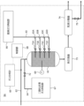
- FIG. 1 is a configuration diagram of a generating device according to an embodiment.
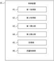
- FIG. 2 is a diagram illustrating an example of a control device.
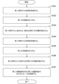
- FIG. 3 is a flow diagram showing the flow of the operating procedure of the generating device.
- FIG. 4 is a diagram showing a first configuration of the removal unit.
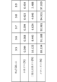
- FIG. 5 is a table showing the ratio of the flow rate of hydrogen gas to the flow rate of carbon dioxide gas and the composition ratio of the product gas.
- FIG. 6 is a diagram showing a second configuration of the removal unit.
- FIG. 7 is a table showing the ratio of the flow rate of hydrogen gas to the flow rate of carbon dioxide gas and the composition ratio of the product gas.
- FIG. 1 is a configuration diagram of a generation device 100 according to an embodiment.
- the generation device 100 shown in FIG. 1 generates methane gas, which is a product gas, and water, by, for example, an exothermic reaction between gaseous hydrogen, which is a raw material gas (reactant gas), and carbon dioxide.
- gaseous hydrogen which is a raw material gas (reactant gas)
- carbon dioxide a raw material gas
- the above chemical reaction is also a reversible reaction.
- the above exothermic reaction is expressed by the following chemical reaction formula.
- the generation device 100 includes a first-stage reaction tower (reactor) 1, a first-stage gas cooling heat exchanger 2, a second-stage reaction tower (reactor) 3, and a second-stage gas cooling heat exchanger 4.
- the heat transfer system includes a heat transfer device 4, a heat medium heater 5, a heat medium heat exchanger 6, gas-liquid separators 7 and 8, a removal section 9, and a storage tank 10.
- the reaction tower 1 generates a product gas by an exothermic reaction of the raw material gas in the catalyst.
- the raw material gas contains, for example, carbon dioxide (CO 2 ) and hydrogen (H 2 ).
- the reaction tower 1 generates a product gas by a catalytic reaction between carbon dioxide and hydrogen.
- the product gas is, for example, methane gas.
- the raw material gas is supplied into the reaction tower 1.
- the reaction tower 1 also generates product water by an exothermic reaction of the raw material gas in the catalyst.
- the reaction tower 1 is connected to a gas cooling heat exchanger 2. Pipes, valves, etc. are provided on a path connecting the reaction tower 1 and the gas cooling heat exchanger 2.
- the gas cooling heat exchanger 2 condenses the product water (water vapor) produced in the reaction tower 1.
- the gas cooling heat exchanger 2 is connected to the gas-liquid separator 7. Pipes, valves, etc. are provided in the path connecting the gas cooling heat exchanger 2 and the gas-liquid separator 7.
- the gas-liquid separator 7 separates the product water (liquid) from the product gas and unreacted raw material gas.
- the reaction tower 3 and the gas-liquid separator 7 are connected.
- the path connecting the reaction tower 3 and the gas-liquid separator 7 is provided with piping, valves, etc.
- the product gas and unreacted raw material gas generated in the reaction tower 1 are sent to the reaction tower 3 via the gas cooling heat exchanger 2 and the gas-liquid separator 7.
- the reaction tower 3 generates the product gas and generated water by the exothermic reaction of the raw material gas in the catalyst. By generating the product gas from the unreacted raw material gas in the reaction tower 3, the generation device 100 is able to generate a highly concentrated product gas.
- the reaction tower 3 and the gas cooling heat exchanger 4 are connected.
- the path connecting the reaction tower 3 and the gas cooling heat exchanger 4 is provided with piping, valves, etc.
- the gas cooling heat exchanger 4 condenses the product water (water vapor) generated in the reaction tower 3.
- the gas cooling heat exchanger 4 and the gas-liquid separator 8 are connected.
- the path connecting the gas cooling heat exchanger 4 and the gas-liquid separator 8 is provided with piping, valves, etc.
- the gas-liquid separator 8 separates the product water (liquid) from the product gas and unreacted raw material gas.
- the product gas is sent from the gas-liquid separator 8 to the removal section 9.
- the removal section 9 removes unreacted raw gas contained in the product gas from the product gas.
- the product gas is sent from the removal section 9 to the storage tank 10.
- the storage tank 10 stores the product gas.
- the gas-liquid separators 7 and 8 are provided with a drain valve 11 for draining the generated water.
- the drain valve 11 may be a valve that opens and closes using the buoyancy of a floating device such as a drain trap, or it may be a valve that electrically detects the water level and opens and closes an electromagnetic valve.
- the generated water is drained from the gas-liquid separators 7 and 8 by the drain valve 11.
- Reaction towers 1 and 3 are filled with a catalyst in advance. Any catalyst that promotes reaction formula (1) may be used.
- the catalyst includes, for example, a stabilized zirconia carrier in which a stabilizing element is dissolved and which has a tetragonal and/or cubic crystal structure, and Ni supported on the stabilized zirconia carrier.
- the stabilizing element may be at least one transition element selected from the group consisting of Mn, Fe, and Co.
- reaction towers 1 and 3 have a jacket structure, and a heat medium can flow in and out of the jacket portion (shell) to exchange heat with the heat generating portion in the reaction tower where the exothermic reaction occurs.
- heat transfer oil is used as the heat medium.
- the heat medium heater 5 and the jacket portion of reaction tower 1 are connected by piping through which the heat medium flows.
- the jacket portion of reaction tower 1 and the jacket portion of reaction tower 3 are connected by piping through which the heat medium flows.
- the piping through which the heat medium flows is provided with a valve or the like.
- the heat medium heater 5 is a heater that heats the heat medium. The heat medium heated by the heat medium heater 5 passes through reaction tower 1 and then through reaction tower 3.
- the jacket portion of the reaction tower 3 and the heat medium heat exchanger 6 are connected by piping through which the heat medium flows.
- the heat medium heat exchanger 6 cools the heat medium that has passed through the reaction towers 1 and 3.
- the heat medium heater 5 and the heat medium heat exchanger 6 are connected by piping through which the heat medium flows.
- the piping connecting the heat medium heater 5 and the heat medium heat exchanger 6 is provided with a heat medium circulation pump 12 that sends the heat medium cooled by the heat medium heat exchanger 6 to the heat medium heater 5.
- the piping through which the heat medium flows is provided with control valves 13 and 14.
- the heat medium that has passed through the reaction towers 1 and 3 can be sent to the heat medium heater 5 via the heat medium heat exchanger 6, or can be sent to the heat medium heater 5 without passing through the heat medium heat exchanger 6.
- the arrangement of the heat medium heat exchanger 6, the heat medium circulation pump 12, and the control valves 13 and 14 may be changed, and the heat medium heated by the heat medium heater 5 may pass through the reaction tower 3 and then through the reaction tower 1.
- the heat medium heat exchanger 6, the heat medium circulation pump 12, and the control valves 13 and 14 are arranged in the path connecting the reaction tower 1 and the heat medium heater 5.
- the generating device 100 includes a cooling tower 15 and a cooling water circulation pump 16.
- the cooling tower 15 cools the cooling water that exchanges heat with the heat medium in the heat medium heat exchanger 6.
- tap water supplied to the cooling tower 15 from outside the system may be used as the cooling water.
- the cooling water circulation pump 16 circulates the cooling water supplied to the cooling tower 15 between the heat medium heat exchanger 6 and the cooling tower 15.
- the generating device 100 includes a cooling tower 17.
- the cooling tower 17 cools the cooling water (refrigerant) for condensing the generated water in the gas cooling heat exchangers 2 and 4.
- the gas cooling heat exchangers 2 and 4 and the cooling tower 17 are interconnected by piping through which the cooling water flows.
- the cooling water cooled by the cooling tower 17 returns to the cooling tower 17 via the gas cooling heat exchangers 2 and 4.
- a chiller may be used instead of the cooling tower 17.
- the generating device 100 includes a first supply device 21 and a second supply device 22.
- the reaction tower 1 and the first supply device 21 are connected by piping, and a first raw material gas containing at least carbon dioxide gas is supplied from the first supply device 21 into the reaction tower 1.
- the reaction tower 1 and the second supply device 22 are connected by piping, and a second raw material gas containing at least hydrogen gas is supplied from the second supply device 22 into the reaction tower 1.
- the first raw material gas may be a mixed gas containing carbon dioxide gas separated and recovered from the exhaust gas and a gas other than carbon dioxide gas.
- the first raw material gas may include a gas whose gas composition varies.
- the second raw material gas may be a mixed gas containing hydrogen gas separated and recovered from the exhaust gas and a gas other than hydrogen gas.
- the second raw material gas may include a gas whose gas composition varies.
- the generating apparatus 100 includes a first measuring device 23, a second measuring device 24, and a control device 25.
- the generating apparatus 100 includes a pipe 31 through which the first raw material gas flows, a pipe 32 through which the second raw material gas flows, and a pipe 33 through which the first raw material gas and the second raw material gas flow.
- the first measuring device 23 measures the flow rate of the first raw material gas supplied to the reaction tower 1 by measuring the flow rate of the first raw material gas flowing through the pipe 31.
- the first measuring device 23 measures the flow rate of the first raw material gas supplied to the reaction tower 1 and outputs a first measurement value.
- the first measuring device 23 is an example of a first measuring unit.
- the second measuring device 24 measures the flow rate of the second raw material gas supplied to the reaction tower 1 by measuring the flow rate of the second raw material gas flowing through the pipe 32.
- the second measuring device 24 measures the flow rate of the second raw material gas supplied to the reaction tower 1 and outputs a second measurement value.
- the second measuring device 24 is an example of a second measuring unit.
- the first measurement value and the second measurement value are sent to the control device 25.
- the first measurement device 23 and the second measurement device 24 are area flow meters, but are not limited to this and may be other flow meters such as a differential pressure flow meter or a Coriolis flow meter.
- Pipe 31 is connected to the first supply device 21, and pipe 32 is connected to the second supply device 22.
- Pipes 31 and 32 are connected to pipe 33, which is connected to the reaction tower 1.
- the first raw material gas flows through pipe 31, the second raw material gas flows through pipe 32, and the first raw material gas and the second raw material gas join at pipe 33.
- the first raw material gas and the second raw material gas are supplied to the reaction tower 1 via pipe 33.
- the generation device 100 includes a flow rate control valve 34 provided in pipe 31, and a flow rate control valve 35 provided in pipe 32.
- Pipe 31 may be connected to the reaction tower 1, and the first raw material gas may be supplied to the reaction tower 1 via pipe 31.
- Pipe 32 may be connected to the reaction tower 1, and the second raw material gas may be supplied to the reaction tower 1 via pipe 32.
- the control device 25 is a controller that controls the overall operation of the generating device 100.
- the control device 25 may also control part of the operation of the generating device 100.
- the control device 25 may be a sequencer such as a PLC (Programmable Logic Controller).
- the control device 25 may be configured with a dedicated device or a general-purpose computer.
- the control device 25 has hardware resources such as a processor (CPU), memory, storage, and a communication I/F.
- the memory may be a RAM.
- the storage may be a non-volatile storage device (e.g., ROM, flash memory, etc.).
- the function of the control device 25 is realized by expanding a program stored in the storage into the memory and executing it with the processor. Note that the configuration of the control device 25 is not limited to these. For example, all or part of the function of the control device 25 may be configured with circuits such as ASIC or FPGA, or all or part of the function of the control device 25 may be executed by a cloud server or other
- the control device 25 includes a first acquisition unit 41, a second acquisition unit 42, a first calculation unit 43, a second calculation unit 44, a memory unit 45, and a flow control unit 46.
- the first acquisition unit 41 acquires the density of the first raw material gas supplied to the reaction tower 1.
- the second acquisition unit 42 acquires the density of the second raw material gas supplied to the reaction tower 1.
- the first calculation unit 43 calculates the flow rate of carbon dioxide gas contained in the first raw material gas supplied to the reaction tower 1.
- the second calculation unit 44 calculates the flow rate of hydrogen gas contained in the second raw material gas supplied to the reaction tower 1.
- the memory unit 45 stores various data.
- the flow control unit 46 controls at least one of the flow rate of the first raw material gas supplied to the reaction tower 1 and the flow rate of the second raw material gas supplied to the reaction tower 1.
- the flow control unit 46 is an example of a control unit.
- the first acquisition unit 41 may acquire the density of the first raw material gas supplied to the reaction tower 1 using analysis data of a first gas analyzer such as an infrared type.
- the first gas analyzer continuously measures the gas composition of the first raw material gas flowing through the pipe 31.
- the first gas analyzer analyzes the first raw material gas flowing through the pipe 31 and measures the concentration (volume %) of at least one type of gas contained in the first raw material gas flowing through the pipe 31.
- the memory unit 45 stores molecular weight data related to the molecular weights of various gases.
- the first acquisition unit 41 calculates the density of the first raw material gas flowing through the pipe 31 based on the analysis data of the first gas analyzer and the molecular weight data stored in the memory unit 45.
- the first acquisition unit 41 acquires the density of the first raw material gas supplied to the reaction tower 1.
- the generation device 100 may be equipped with the first gas analyzer.
- the first measurement device 23 may have the first gas analyzer, or the control device 25 may have the first gas analyzer.
- the analysis data of the first gas analyzer may be sent to the control device 25.
- the density of the first raw material gas supplied to the reaction tower 1 and the analysis data of the first gas analyzer may be stored in the memory unit 45.
- the first acquisition unit 41 may acquire the density of the first raw material gas supplied to the reaction tower 1 using the measurement data of the first gas density meter.
- the first gas density meter measures the density of the first raw material gas flowing through the pipe 31.
- the generation device 100 may be equipped with the first gas density meter.
- the first measurement device 23 may have the first gas density meter, or the control device 25 may have the first gas density meter.
- the measurement data of the first gas density meter may be sent to the control device 25.
- the measurement data of the first gas density meter may be stored in the memory unit 45.
- the second acquisition unit 42 may acquire the density of the second raw material gas supplied to the reaction tower 1 using analysis data of a second gas analyzer such as an infrared type.
- the second gas analyzer continuously measures the gas composition of the second raw material gas flowing through the pipe 32.
- the second gas analyzer analyzes the second raw material gas flowing through the pipe 32 and measures the concentration (volume %) of at least one type of gas contained in the second raw material gas flowing through the pipe 32.
- the memory unit 45 stores molecular weight data related to the molecular weights of various gases.
- the second acquisition unit 42 calculates the density of the second raw material gas flowing through the pipe 32 based on the analysis data of the second gas analyzer and the molecular weight data stored in the memory unit 45.
- the second acquisition unit 42 acquires the density of the second raw material gas supplied to the reaction tower 1.
- the generation device 100 may be equipped with a second gas analyzer.
- the second measurement device 24 may have a second gas analyzer, or the control device 25 may have a second gas analyzer.
- the analysis data of the second gas analyzer may be sent to the control device 25.
- the density of the second raw material gas supplied to the reaction tower 1 and the analysis data of the second gas analyzer may be stored in the memory unit 45.
- the second acquisition unit 42 may acquire the density of the second raw material gas supplied to the reaction tower 1 using the measurement data of the second gas density meter.
- the second gas density meter measures the density of the second raw material gas flowing through the pipe 32.
- the generation device 100 may be equipped with the second gas density meter.
- the second measurement device 24 may have the second gas density meter, or the control device 25 may have the second gas density meter.
- the measurement data of the second gas density meter may be sent to the control device 25.
- the measurement data of the second gas density meter may be stored in the memory unit 45.
- the first calculation unit 43 acquires the carbon dioxide concentration in the first raw material gas supplied to the reaction tower 1.
- the method of acquiring the carbon dioxide concentration in the first calculation unit 43 is not particularly limited.
- An analyzer such as a gas chromatograph may measure the carbon dioxide concentration in the first raw material gas flowing through the pipe 31, and the first calculation unit 43 may acquire the measurement data.
- the first calculation unit 43 may acquire the carbon dioxide concentration by calculating the carbon dioxide concentration in the first raw material gas supplied to the reaction tower 1 using the analysis data of the first gas analyzer.
- the first calculation unit 43 calculates the flow rate of carbon dioxide gas contained in the first raw material gas supplied to the reaction tower 1 based on the density of the first raw material gas supplied to the reaction tower 1, the first measurement value, and the carbon dioxide concentration in the first raw material gas supplied to the reaction tower 1.
- the second calculation unit 44 acquires the hydrogen concentration in the second raw material gas supplied to the reaction tower 1.
- the method of acquiring the hydrogen concentration in the second calculation unit 44 is not particularly limited.
- An analyzer such as a gas chromatograph may measure the hydrogen concentration in the second raw material gas flowing through the pipe 32, and the second calculation unit 44 may acquire the measurement data.
- the second calculation unit 44 may acquire the hydrogen concentration by calculating the hydrogen concentration in the second raw material gas supplied to the reaction tower 1 using the analysis data of the second gas analyzer.
- the second calculation unit 44 calculates the flow rate of hydrogen gas contained in the second raw material gas supplied to the reaction tower 1 based on the density of the second raw material gas supplied to the reaction tower 1, the second measurement value, and the hydrogen concentration in the second raw material gas supplied to the reaction tower 1.
- the flow rate control unit 46 controls at least one of the flow rate of the first raw material gas supplied to the reaction tower 1 and the flow rate of the second raw material gas supplied to the reaction tower 1 based on the flow rate of carbon dioxide gas contained in the first raw material gas supplied to the reaction tower 1 and the flow rate of hydrogen gas contained in the second raw material gas supplied to the reaction tower 1. This makes it possible to reduce the remaining amount of carbon dioxide gas and the remaining amount of hydrogen gas in the product gas generated in the reaction tower 1. Therefore, the remaining amount of unreacted gas in the product gas generated in the reaction tower 1 can be reduced, and high-concentration methane gas can be generated.
- the generator 100 can reduce the amount of unreacted gas remaining in the product gas generated in the reaction tower 1 even when the first feed gas is a mixed gas containing carbon dioxide gas or a gas whose gas composition varies, making it possible to generate high-concentration methane gas. Also, the generator 100 can reduce the amount of unreacted gas remaining in the product gas generated in the reaction tower 1 even when the second feed gas is a mixed gas containing hydrogen gas or a gas whose gas composition varies, making it possible to generate high-concentration methane gas.
- the flow rate control unit 46 controls the flow rate of the first raw material gas supplied to the reaction tower 1 by controlling the flow rate control valve 34.
- the flow rate control valve 34 controls the flow rate of the first raw material gas flowing through the pipe 31.
- the flow rate control unit 46 controls the flow rate of the second raw material gas supplied to the reaction tower 1 by controlling the flow rate control valve 35.
- the flow rate control valve 35 controls the flow rate of the second raw material gas flowing through the pipe 32.
- the flow rate control unit 46 controls the flow rate of the first raw material gas supplied to the reaction tower 1, and may set the flow rate of the second raw material gas supplied to the reaction tower 1 to the natural flow rate.
- the flow rate control unit 46 controls the flow rate of the first raw material gas supplied to the reaction tower 1, and may set the flow rate of the second raw material gas supplied to the reaction tower 1 to a set flow rate.
- the flow rate control unit 46 controls the flow rate of the second raw material gas supplied to the reaction tower 1, and may set the flow rate of the first raw material gas supplied to the reaction tower 1 to the natural flow rate.
- the flow rate control unit 46 may control the flow rate of the second raw material gas supplied to the reaction tower 1, and may set the flow rate of the first raw material gas supplied to the reaction tower 1 to a set flow rate.
- FIG. 3 is a flow diagram showing the flow of the operation procedure of the generator 100.
- the first supply device 21 is started, and the first supply device 21 starts supplying the first raw material gas to the reaction tower 1, and the second supply device 22 is started, and the second supply device 22 starts supplying the second raw material gas to the reaction tower 1.
- the first acquisition unit 41 acquires the density of the first raw material gas supplied to the reaction tower 1.
- the first measurement device 23 measures the flow rate of the first raw material gas supplied to the reaction tower 1 and outputs a first measurement value.
- the first calculation unit 43 calculates the flow rate of carbon dioxide gas contained in the first raw material gas supplied to the reaction tower 1.
- step S104 the second acquisition unit 42 acquires the density of the second raw material gas supplied to the reaction tower 1.
- step S105 the second measurement device 24 measures the flow rate of the second raw material gas supplied to the reaction tower 1 and outputs a second measurement value.
- step S106 the second calculation unit 44 calculates the flow rate of hydrogen gas contained in the second raw material gas supplied to the reaction tower 1.
- the flow rate control unit 46 controls at least one of the flow rate of the first raw material gas supplied to the reaction tower 1 and the flow rate of the second raw material gas supplied to the reaction tower 1 by controlling at least one of the flow rate control valve 34 and the flow rate control valve 35.
- the flow rate control valve 34 is an example of a first flow rate control valve.
- the flow rate control unit 46 controls at least one of the flow rate of the first raw material gas supplied to the reaction tower 1 and the flow rate of the second raw material gas supplied to the reaction tower 1 based on the flow rate of carbon dioxide gas contained in the first raw material gas supplied to the reaction tower 1 and the flow rate of hydrogen gas contained in the second raw material gas supplied to the reaction tower 1.
- the flow rate control unit 46 sends a control signal to the flow rate control valve 34 for controlling the flow rate control valve 34.
- the flow rate control valve 34 controls the flow rate of the first raw material gas flowing through the piping 31 in response to the control signal from the flow rate control unit 46.
- the flow rate control unit 46 sends a control signal to the flow rate control valve 35 for controlling the flow rate control valve 35.
- the flow rate control valve 35 controls the flow rate of the second source gas flowing through the pipe 32 in response to a control signal from the flow rate control unit 46.
- Steps S101 to S107 may be repeated at regular or irregular intervals. The order of steps S101 to S107 may be changed.
- Step S101 may be performed after step S102.
- Step S104 may be performed after step S105.
- Steps S101 to S103 may be performed after steps S104 to S106.
- the flow rate control unit 46 may control at least one of the flow rate of the first raw material gas supplied to the reaction tower 1 and the flow rate of the second raw material gas supplied to the reaction tower 1 so that the ratio between the flow rate of carbon dioxide gas contained in the first raw material gas supplied to the reaction tower 1 and the flow rate of hydrogen gas contained in the second raw material gas supplied to the reaction tower 1 becomes a predetermined ratio.
- the predetermined ratio is, for example, 1.0:4.0, but is not limited to this ratio, and the predetermined ratio may be a value close to 1.0:4.0.
- the predetermined ratio may be 1.0:4.0 or more.
- the predetermined ratio may be 1.0:4.0 or more and 4.2 or less.
- the predetermined ratio may be 1.0:4.0 or more and 4.1 or less.
- the predetermined ratio may be less than 1.0:4.0.
- the predetermined ratio may be 1.0:3.8 or more and 4.0 or less.
- the predetermined ratio may be 1.0:3.9 or more and 4.0 or less.
- the predetermined ratio may be 1.0:3.8 or more and 4.2 or less.
- the predetermined ratio may be 1.0:3.9 or more and 4.1 or less.
- the predetermined ratio may be determined in advance by experiment or simulation, and may be stored in the memory unit 45. The closer the ratio of the flow rate of carbon dioxide gas contained in the first raw material gas supplied to the reaction tower 1 to the flow rate of hydrogen gas contained in the second raw material gas supplied to the reaction tower 1 is to 1.0:4.0, the more the remaining amount of carbon dioxide gas and the remaining amount of hydrogen gas in the product gas generated in the reaction tower 1 are reduced.
- the flow rate control unit 46 may control at least one of the flow rate of the first raw material gas supplied to the reaction tower 1 and the flow rate of the second raw material gas supplied to the reaction tower 1 so that the ratio of the flow rate of the hydrogen gas to the flow rate of the carbon dioxide gas supplied to the reaction tower 1 becomes a predetermined value.
- the predetermined value is, for example, 4.0, but is not limited to this value, and the predetermined value may be a value close to 4.0.
- the predetermined value may be 4.0 or more.
- the predetermined value may be 4.0 or more and 4.2 or less.
- the predetermined value may be 4.0 or more and 4.1 or less.
- the predetermined value may be less than 4.0.
- the predetermined value may be 3.8 or more and less than 4.0.
- the predetermined value may be 3.9 or more and less than 4.0.
- the predetermined value may be 3.8 or more and 4.2 or less.
- the predetermined value may be 3.9 or more and 4.1 or less.
- the predetermined value may be determined in advance by experiment or simulation, and may be stored in the memory unit 45. The closer the ratio of the flow rate of hydrogen gas to the flow rate of carbon dioxide gas supplied to reaction tower 1 is to 4, the more the remaining amount of carbon dioxide gas and hydrogen gas in the product gas generated in reaction tower 1 is reduced.
- the flow rate control unit 46 may determine a first control value for the flow rate of the first raw material gas supplied to the reaction tower 1 based on the flow rate of carbon dioxide gas contained in the first raw material gas supplied to the reaction tower 1, the flow rate of hydrogen gas contained in the second raw material gas supplied to the reaction tower 1, and a predetermined ratio.
- the flow rate control unit 46 may control the flow rate of the first raw material gas supplied to the reaction tower 1 based on the first control value.
- the flow rate control unit 46 may set the flow rate of the second raw material gas supplied to the reaction tower 1 to a natural flow rate or a set flow rate. This type of control is suitable for a system that utilizes hydrogen gas generated by renewable energy as effectively as possible, for example.
- the flow rate control unit 46 may determine a second control value for the flow rate of the second raw material gas supplied to the reaction tower 1 based on the flow rate of carbon dioxide gas contained in the first raw material gas supplied to the reaction tower 1, the flow rate of hydrogen gas contained in the second raw material gas supplied to the reaction tower 1, and a predetermined ratio.
- the flow rate control unit 46 may control the flow rate of the second raw material gas supplied to the reaction tower 1 based on the second control value.
- the flow rate control unit 46 may set the flow rate of the first raw material gas supplied to the reaction tower 1 to a natural flow rate or a set flow rate. This type of control is suitable for a system that utilizes the separated and recovered carbon dioxide gas as effectively as possible, for example.
- the flow rate control unit 46 may control the flow rate of the first raw material gas supplied to the reaction tower 1 based on the first control value, and may also control the flow rate of the second raw material gas supplied to the reaction tower 1 based on the second control value.
- the first supply device 21 may supply a first supply gas containing at least carbon dioxide gas and hydrogen gas into the reaction tower 1.
- the first calculation unit 43 may acquire the hydrogen concentration in the first raw material gas supplied to the reaction tower 1, and calculate the flow rate of hydrogen gas contained in the first raw material gas supplied to the reaction tower 1 based on the density of the first raw material gas supplied to the reaction tower 1, the first measurement value, and the hydrogen concentration in the first raw material gas supplied to the reaction tower 1.
- the flow rate control unit 46 may calculate a first total flow rate which is the sum of the flow rate of hydrogen gas contained in the first raw material gas supplied to the reaction tower 1 and the flow rate of hydrogen gas contained in the second raw material gas supplied to the reaction tower 1.
- the flow rate control unit 46 may control at least one of the flow rate of the first raw material gas supplied to the reaction tower 1 and the flow rate of the second raw material gas supplied to the reaction tower 1 so that the ratio of the flow rate of carbon dioxide gas contained in the first raw material gas supplied to the reaction tower 1 to the first total flow rate is a predetermined ratio. The closer the ratio of the flow rate of the carbon dioxide gas contained in the first raw material gas supplied to the reaction tower 1 to the first total flow rate is to 1.0:4.0, the more the remaining amount of carbon dioxide gas and the remaining amount of hydrogen gas in the product gas generated in the reaction tower 1 are reduced.
- the flow rate control unit 46 may determine a first control value for the flow rate of the first raw material gas supplied to the reaction tower 1 based on the first total flow rate, the flow rate of carbon dioxide gas contained in the first raw material gas supplied to the reaction tower 1, and a predetermined ratio.
- the flow rate control unit 46 may control the flow rate of the first raw material gas supplied to the reaction tower 1 based on the first control value.
- the flow rate control unit 46 may set the flow rate of the second raw material gas supplied to the reaction tower 1 to a natural flow rate or a set flow rate. This type of control is suitable for a system that utilizes hydrogen gas generated by renewable energy as effectively as possible, for example.
- the flow rate control unit 46 may determine a second control value for the flow rate of the second raw material gas supplied to the reaction tower 1 based on the first total flow rate, the flow rate of carbon dioxide gas contained in the first raw material gas supplied to the reaction tower 1, and a predetermined ratio.
- the flow rate control unit 46 may control the flow rate of the second raw material gas supplied to the reaction tower 1 based on the second control value.
- the flow rate control unit 46 may set the flow rate of the first raw material gas supplied to the reaction tower 1 to a natural flow rate or a set flow rate. This type of control is suitable for a system that utilizes the separated and recovered carbon dioxide gas as effectively as possible, for example.
- the flow rate control unit 46 may control the flow rate of the first raw material gas supplied to the reaction tower 1 based on the first control value, and also control the flow rate of the second raw material gas supplied to the reaction tower 1 based on the second control value.
- the second supply device 22 may supply a second supply gas containing at least hydrogen gas and carbon dioxide gas into the reaction tower 1.
- the second calculation unit 44 may acquire the carbon dioxide concentration in the second raw material gas supplied to the reaction tower 1, and calculate the flow rate of carbon dioxide gas contained in the second raw material gas supplied to the reaction tower 1 based on the density of the second raw material gas supplied to the reaction tower 1, the second measurement value, and the carbon dioxide concentration in the second raw material gas supplied to the reaction tower 1.
- the flow rate control unit 46 may calculate a second total flow rate which is the sum of the flow rate of carbon dioxide gas contained in the first raw material gas supplied to the reaction tower 1 and the flow rate of carbon dioxide gas contained in the second raw material gas supplied to the reaction tower 1.
- the flow rate control unit 46 may control at least one of the flow rate of the first raw material gas supplied to the reaction tower 1 and the flow rate of the second raw material gas supplied to the reaction tower 1 so that the ratio of the second total flow rate to the flow rate of hydrogen gas contained in the second raw material gas supplied to the reaction tower 1 is a predetermined ratio. The closer the ratio of the second total flow rate to the flow rate of hydrogen gas contained in the second feed gas supplied to reaction tower 1 is to 1.0:4.0, the more the remaining amount of carbon dioxide gas and the remaining amount of hydrogen gas in the product gas generated in reaction tower 1 are reduced.
- the flow rate control unit 46 may determine a first control value for the flow rate of the first raw material gas supplied to the reaction tower 1 based on the second total flow rate, the flow rate of hydrogen gas contained in the second raw material gas supplied to the reaction tower 1, and a predetermined ratio.
- the flow rate control unit 46 may control the flow rate of the first raw material gas supplied to the reaction tower 1 based on the first control value.
- the flow rate control unit 46 may set the flow rate of the second raw material gas supplied to the reaction tower 1 to a natural flow rate or a set flow rate. This type of control is suitable for a system that utilizes hydrogen gas generated by renewable energy as effectively as possible, for example.
- the flow rate control unit 46 may determine a second control value for the flow rate of the second raw material gas supplied to the reaction tower 1 based on the second total flow rate, the flow rate of hydrogen gas contained in the second raw material gas supplied to the reaction tower 1, and a predetermined ratio.
- the flow rate control unit 46 may control the flow rate of the second raw material gas supplied to the reaction tower 1 based on the second control value.
- the flow rate control unit 46 may set the flow rate of the first raw material gas supplied to the reaction tower 1 to a natural flow rate or a set flow rate. This type of control is suitable for a system that utilizes the separated and recovered carbon dioxide gas as effectively as possible, for example.
- the flow rate control unit 46 may control the flow rate of the first raw material gas supplied to the reaction tower 1 based on the first control value, and also control the flow rate of the second raw material gas supplied to the reaction tower 1 based on the second control value.
- the first supply device 21 may supply a first supply gas containing at least carbon dioxide gas and hydrogen gas into the reaction tower 1, and the second supply device 22 may supply a second supply gas containing at least hydrogen gas and carbon dioxide gas into the reaction tower 1.
- the first calculation unit 43 may acquire the hydrogen concentration in the first raw material gas supplied to the reaction tower 1, and calculate the flow rate of hydrogen gas contained in the first raw material gas supplied to the reaction tower 1 based on the density of the first raw material gas supplied to the reaction tower 1, the first measurement value, and the hydrogen concentration in the first raw material gas supplied to the reaction tower 1.
- the second calculation unit 44 may acquire the carbon dioxide concentration in the second raw material gas supplied to the reaction tower 1, and calculate the flow rate of carbon dioxide gas contained in the second raw material gas supplied to the reaction tower 1 based on the density of the second raw material gas supplied to the reaction tower 1, the second measurement value, and the carbon dioxide concentration in the second raw material gas supplied to the reaction tower 1.
- the flow rate control unit 46 may calculate a first total flow rate by summing the flow rate of hydrogen gas contained in the first raw material gas supplied to the reaction tower 1 and the flow rate of hydrogen gas contained in the second raw material gas supplied to the reaction tower 1.
- the flow rate control unit 46 may calculate a second total flow rate by summing the flow rate of carbon dioxide gas contained in the first raw material gas supplied to the reaction tower 1 and the flow rate of carbon dioxide gas contained in the second raw material gas supplied to the reaction tower 1.
- the flow rate control unit 46 may control at least one of the flow rate of the first raw material gas supplied to the reaction tower 1 and the flow rate of the second raw material gas supplied to the reaction tower 1 so that the ratio of the first total flow rate to the second total flow rate is a predetermined ratio. The closer the ratio of the first total flow rate to the second total flow rate is to 1.0:4.0, the more the remaining amount of carbon dioxide gas and the remaining amount of hydrogen gas in the product gas generated in the reaction tower 1 are reduced.
- the flow rate control unit 46 may determine a first control value for the flow rate of the first raw material gas supplied to the reaction tower 1 based on the first total flow rate, the second total flow rate, and a predetermined ratio. The flow rate control unit 46 may control the flow rate of the first raw material gas supplied to the reaction tower 1 based on the first control value. The flow rate control unit 46 may set the flow rate of the second raw material gas supplied to the reaction tower 1 to a natural flow rate or a set flow rate. This type of control is suitable for a system that utilizes hydrogen gas generated by renewable energy as effectively as possible, for example.
- the flow rate control unit 46 may determine a second control value for the flow rate of the second raw material gas supplied to the reaction tower 1 based on the first total flow rate, the second total flow rate, and a predetermined ratio.
- the flow rate control unit 46 may control the flow rate of the second raw material gas supplied to the reaction tower 1 based on the second control value.
- the flow rate control unit 46 may set the flow rate of the first raw material gas supplied to the reaction tower 1 to a natural flow rate or a set flow rate. This type of control is suitable for a system that utilizes the separated and recovered carbon dioxide gas as effectively as possible, for example.
- a first raw material gas containing carbon dioxide gas ( CO2 gas) and nitrogen gas ( N2 gas) is supplied from a first supply device 21 into the reaction tower 1, and a second raw material gas containing hydrogen gas ( H2 gas) and carbon dioxide gas ( CO2 gas) is supplied from a second supply device 22 into the reaction tower 1.
- the concentration of carbon dioxide gas contained in the first raw material gas is 80%, and the concentration of nitrogen gas contained in the first raw material gas is 20%.
- the concentration of hydrogen gas contained in the second raw material gas is 95%, and the concentration of carbon dioxide gas contained in the second raw material gas is 5%.
- the first raw material gas is a CO2- rich gas
- the second raw material gas is a H2 - rich gas.
- the first measuring device 23 measures the flow rate of the first raw material gas supplied to the reaction tower 1 and outputs a first measured value.
- the first measuring device 23 measures the flow rate (volumetric flow rate) of the first raw material gas at a gas density of design conditions.
- the gas density of design conditions is the density of the first raw material gas (1964 g/m 3 ) when the carbon dioxide concentration in the first raw material gas is 100%.
- the first measured value is 100 Nm 3 /h.
- the first calculation unit 43 acquires the carbon dioxide concentration (80%) in the first raw material gas supplied to the reaction tower 1.
- the first calculation unit 43 calculates the flow rate of carbon dioxide gas contained in the first raw material gas supplied to the reaction tower 1 based on the density of the first raw material gas supplied to the reaction tower 1 (1820 g/m 3 ), the first measured value (100 Nm 3 /h), and the carbon dioxide concentration (80%) in the first raw material gas supplied to the reaction tower 1.
- the first calculation unit 43 corrects the first measured value (100 Nm 3 /h) using the gas density and the density of the first raw material gas of the design condition.
- the first calculation unit 43 multiplies the corrected first measured value (103.8 Nm 3 /h) by the carbon dioxide concentration (80%) in the first raw material gas supplied to the reaction tower 1 to calculate the flow rate (83 Nm 3 /h) of carbon dioxide gas contained in the first raw material gas supplied to the reaction tower 1.
- the second measuring device 24 measures the flow rate of the second raw material gas supplied to the reaction tower 1 and outputs a second measured value.
- the second measuring device 24 measures the flow rate (volumetric flow rate) of the second raw material gas at a gas density of a design condition.
- the gas density of the design condition is the density (89.3 g/m 3 ) of the second raw material gas when the hydrogen concentration in the second raw material gas is 100%.
- the second measured value is 400 Nm 3 /h.
- the second calculation unit 44 acquires the hydrogen concentration (95%) in the second raw material gas supplied to the reaction tower 1.
- the second calculation unit 44 calculates the flow rate of the hydrogen carbon gas contained in the second raw material gas supplied to the reaction tower 1 based on the density (183 g/m 3 ) of the second raw material gas supplied to the reaction tower 1, the second measurement value (400 Nm 3 /h), and the hydrogen concentration (95%) in the second raw material gas supplied to the reaction tower 1.
- the second calculation unit 44 corrects the second measured value (400 Nm3 /h) using the gas density under the design conditions and the density of the second raw material gas.
- the second calculation unit 44 multiplies the corrected second measured value (279 Nm3 /h) by the hydrogen concentration (95%) in the second raw material gas supplied to the reaction tower 1 to calculate the flow rate (265 Nm3 /h) of hydrogen gas contained in the second raw material gas supplied to the reaction tower 1.
- the second calculation unit 44 acquires the carbon dioxide concentration (5%) in the second raw material gas supplied to the reaction tower 1.
- the second calculation unit 44 calculates the flow rate of carbon dioxide gas contained in the second raw material gas supplied to the reaction tower 1 based on the density (183 g/m 3 ) of the second raw material gas supplied to the reaction tower 1, the second measurement value (400 Nm 3 /h), and the carbon dioxide concentration (5%) in the second raw material gas supplied to the reaction tower 1.
- the second calculation unit 44 corrects the second measurement value (400 Nm 3 /h) using the gas density of the design conditions and the density of the second raw material gas.
- the second calculation unit 44 multiplies the corrected second measured value (279 Nm 3 /h) by the carbon dioxide concentration (5%) in the second raw material gas supplied to the reaction tower 1 to calculate the flow rate (14 Nm 3 /h) of carbon dioxide gas contained in the second raw material gas supplied to the reaction tower 1.
- the second calculation unit 44 multiplies the corrected second measured value (279 Nm 3 /h) by the carbon dioxide concentration (5%) in the second raw material gas supplied to the reaction tower 1 to calculate the flow rate (14 Nm 3 /h) of carbon dioxide gas contained in the second raw material gas supplied to the reaction tower 1.
- the flow rate control unit 46 controls at least one of the flow rate of the first raw material gas supplied to the reaction tower 1 and the flow rate of the second raw material gas supplied to the reaction tower 1 based on the flow rate (83 Nm 3 /h) of carbon dioxide gas contained in the first raw material gas supplied to the reaction tower 1 and the flow rate (296.2 Nm 3 /h) of hydrogen gas contained in the second raw material gas supplied to the reaction tower 1.
- the flow rate control unit 46 controls the flow rate of the second raw material gas supplied to the reaction tower 1.
- the flow rate control unit 46 calculates a first total flow rate (97 Nm 3 /h) which is the sum of the flow rate (83 Nm 3 /h) of carbon dioxide gas contained in the first raw material gas supplied to the reaction tower 1 and the flow rate (14 Nm 3 /h) of carbon dioxide gas contained in the second raw material gas supplied to the reaction tower 1 .
- the flow rate control unit 46 controls the flow rate of the second raw material gas supplied to the reaction tower 1 so that the ratio between the first total flow rate and the flow rate of hydrogen gas contained in the second raw material gas supplied to the reaction tower 1 becomes a predetermined ratio (1.0:4.0).
- the ratio between the first total flow rate and the flow rate of hydrogen gas contained in the second raw material gas supplied to the reaction tower 1 is 1.0:2.7.
- the flow rate control unit 46 controls the flow rate of the second raw material gas so that the second measurement value becomes the target measurement value.
- the flow rate control unit 46 sets the flow rate of the first raw material gas supplied to the reaction tower 1 to the natural flow rate or a set flow rate.
- the flow rate control unit 46 calculates the target measurement value based on the following formula (3).
- the density of the first source gas in standard conditions and the density of the second source gas in standard conditions are used, but this is not limiting.
- the pressure and temperature may be measured, and the density of the first source gas and the density of the second source gas may be corrected based on the measured pressure and temperature.
- FIG. 4 is a diagram showing a first configuration of the removal unit 9.
- the removal unit 9A includes a tank 61, pipes 62, 63, and 64 connected to the tank 61, a gas analyzer 65, an oxygen gas supply unit 66, a carbon dioxide gas supply unit 67, a control unit 68, and a temperature sensor 69.
- the removal unit 9A removes hydrogen gas from the product gas containing methane gas and hydrogen gas.
- FIG. 5 is a table showing the ratio of the flow rate of hydrogen gas to the flow rate of carbon dioxide gas supplied to the reaction tower 1 ( H2 / CO2 ratio) and the composition ratio (%) of the product gas discharged from the reaction tower 3.
- N.D. in FIG. 5 means not detectable.
- the H2 / CO2 ratio is 4.05 or more
- the product gas discharged from the reaction tower 3 contains methane gas and hydrogen gas, but does not contain carbon dioxide gas.
- the flow rate control unit 46 may control at least one of the flow rate of the first raw material gas supplied to the reaction tower 1 and the flow rate of the second raw material gas supplied to the reaction tower 1 so that the ratio of the flow rate of the hydrogen gas to the flow rate of the carbon dioxide gas supplied to the reaction tower 1 is 4.0 or more.
- the flow rate control unit 46 may control at least one of the flow rate of the first raw material gas supplied to the reaction tower 1 and the flow rate of the second raw material gas supplied to the reaction tower 1 so that the ratio of the flow rate of the hydrogen gas to the flow rate of the carbon dioxide gas supplied to the reaction tower 1 is 4.0 or more and 4.2 or less (preferably 4.0 or more and 4.1 or less).
- the tank 61 contains a filler.
- the tank 61 has two or more gas supply ports and nozzles.
- a product gas containing methane gas and hydrogen gas is supplied from the gas-liquid separator 8 into the tank 61.
- the product gas flows through the pipe 62 and is sent to the tank 61.
- the gas analyzer 65 analyzes the product gas flowing through the pipe 62 and calculates the concentration of hydrogen gas in the product gas.
- Oxygen gas is supplied into tank 61 from oxygen gas supply unit 66.
- Oxygen gas supply unit 66 may be a solid polymer water electrolysis device or alkaline water electrolysis device capable of supplying oxygen gas, or may be a gas cylinder or storage tank capable of storing oxygen gas.
- Oxygen gas flows through pipe 63 and is sent into tank 61.
- Pipe 63 branches into pipes 63A to 63D, and oxygen gas is sent into tank 61 from multiple locations. Pipe 63A is located closest to the product gas supply port in tank 61, and pipe 63D is located farthest from the product gas supply port in tank 61.
- the piping 63A to 63D are provided with adjustment valves 71A to 71D.
- the control unit 68 controls the oxygen gas supply unit 66 to start and stop the supply of oxygen gas to the tank 61.
- the control unit 68 controls the flow rate of oxygen gas supplied into the tank 61 by controlling the adjustment valves 71A to 71D.
- the adjustment valve 71A controls the flow rate of oxygen gas flowing through the piping 63A.
- the adjustment valve 71B controls the flow rate of oxygen gas flowing through the piping 63B.
- the adjustment valve 71C controls the flow rate of oxygen gas flowing through the piping 63C.
- the adjustment valve 71D controls the flow rate of oxygen gas flowing through the piping 63D.
- the control unit 68 may control the start and stop of the supply of oxygen gas to the tank 61 by controlling the opening and closing of the adjustment valves 71A to 71D.
- Carbon dioxide gas is supplied from the carbon dioxide gas supply unit 67 into the tank 61.
- the carbon dioxide gas supply unit 67 may be a gas cylinder, a storage tank, etc. capable of storing carbon dioxide gas.
- Carbon dioxide gas may be supplied into the tank 61 from the first supply device 21.
- the carbon dioxide gas flows through the piping 64 and is sent into the tank 61.
- the piping 64 is provided with an adjustment valve 72.
- the control unit 68 controls the start and stop of the supply of carbon dioxide gas to the tank 61 by controlling the carbon dioxide gas supply unit 67 or the first supply device 21.
- the control unit 68 controls the flow rate of the carbon dioxide gas supplied into the tank 61 by controlling the adjustment valve 72.
- the adjustment valve 72 controls the flow rate of the carbon dioxide gas flowing through the piping 64.
- the control unit 68 may control the start and stop of the supply of carbon dioxide gas to the tank 61 by controlling the opening and closing of the adjustment valve 72.
- the hydrogen gas contained in the product gas supplied into the tank 61 reacts with the oxygen gas supplied into the tank 61 to generate water (steam), and the hydrogen gas is removed from the product gas.
- the removal unit 9A may include a heater (heating unit) for heating the inside of the tank 61.
- the removal unit 9A may heat the inside of the tank 61 when the hydrogen gas and oxygen gas react with each other in the tank 61 to generate water.
- the control unit 68 controls the flow rate of the oxygen gas supplied into the tank 61 according to the hydrogen concentration in the product gas. When the hydrogen concentration in the product gas is relatively high, the oxygen concentration supplied from the port close to the product gas supply port in the tank 61 is controlled to a level not exceeding the explosion limit.
- the control unit 68 controls the adjustment valves 71A to 71D to control the flow rate of the oxygen gas flowing through the pipes 63A to 63D so that the flow rate of the oxygen gas flowing through the pipes 63A to 63D increases from the pipes 63A to 63D.
- the removal section 9A includes a heat exchanger (condenser) 73 and a gas-liquid separator 74.
- the product gas and water vapor are sent from the tank 61 to the heat exchanger 73.
- the heat exchanger 73 condenses the generated water generated in the tank 61.
- the heat exchanger 73 and the gas-liquid separator 74 are connected.
- the path connecting the heat exchanger 73 and the gas-liquid separator 74 is provided with piping, valves, etc.
- the gas-liquid separator 74 separates the generated water (liquid) from the product gas.
- the gas-liquid separator 74 is provided with a drain valve 75 for discharging the generated water.
- the drain valve 75 may be a valve that opens and closes using the buoyancy of a float such as a drain trap, or it may be a valve that opens and closes an electromagnetic valve by electrically detecting the water level.
- the generated water is discharged from the gas-liquid separator 74 by the drain valve 75.
- the product gas after separation of the generated water from the product gas contains methane gas and water vapor.
- the product gas may be dried by passing Dry- H2 gas supplied from a solid polymer water electrolysis device, an alkaline water electrolysis device, a gas cylinder, a storage tank, or the like through the product gas.
- the Dry- H2 gas becomes Wet- H2 gas after passing through the product gas.
- the Wet- H2 gas may be used as the second raw material gas.
- the Wet- H2 gas may be supplied to at least one of the reaction tower 1 and the reaction tower 3.
- the product gas from which hydrogen gas has been removed is sent from the gas-liquid separator 74 to the storage tank 10.
- the amount of hydrogen gas remaining in the product gas is reduced, making it possible to obtain a product gas containing a high concentration of methane gas.
- the hydrogen gas separated from the product gas as the second feed gas or supplying the hydrogen gas separated from the product gas to at least one of reaction towers 1 and 3, it is possible to reduce energy loss.
- FIG. 6 is a diagram showing a second configuration of the removal unit 9.
- the removal unit 9 having the second configuration is shown as removal unit 9B.
- the removal unit 9B includes tanks 81, 82, pipes 83-86 connected to the tanks 81, 82, and a control unit 87.
- the removal unit 9B removes carbon dioxide gas from the product gas containing methane gas and carbon dioxide gas.
- the removal unit 9A shown in FIG. 6 includes two tanks, but is not limited to this, and the removal unit 9A may include three or more tanks.
- the flow rate control unit 46 may control at least one of the flow rate of the first raw material gas supplied to the reaction tower 1 and the flow rate of the second raw material gas supplied to the reaction tower 1 so that the ratio of the flow rate of hydrogen gas to the flow rate of carbon dioxide gas supplied to the reaction tower 1 is less than 4.0.
- the flow rate control unit 46 may control at least one of the flow rate of the first raw material gas supplied to the reaction tower 1 and the flow rate of the second raw material gas supplied to the reaction tower 1 so that the ratio of the flow rate of hydrogen gas to the flow rate of carbon dioxide gas supplied to the reaction tower 1 is 3.5 or more and less than 4.0.
- the tanks 81 and 82 contain an occlusion material such as calcium oxide.
- a product gas containing methane gas and carbon dioxide gas is supplied from the gas-liquid separator 8 into the tank 81.
- the product gas flows through a pipe 83 and is sent into the tanks 81 and 82.
- the product gas may be dried by passing Dry- H2 gas supplied from a solid polymer water electrolysis device, an alkaline water electrolysis device, a gas cylinder, a storage tank, or the like through the product gas.
- the Dry- H2 gas becomes Wet- H2 gas after passing through the product gas.
- the Wet- H2 gas may be used as a second raw material gas.
- the Wet- H2 gas may be supplied to at least one of the reaction towers 1 and 3.
- Pipe 83 branches into pipes 83A and 83B.
- Pipe 83A is provided with an adjustment valve 91
- pipe 83B is provided with an adjustment valve 92.
- the control unit 87 controls the adjustment valves 91 and 92.
- Adjustment valve 91 controls the flow of product gas in pipe 83A.
- Adjustment valve 92 controls the flow of product gas in pipe 83B.
- Product gas is supplied into tank 81, and the storage material in tank 81 removes the carbon dioxide gas from the product gas by storing the carbon dioxide gas contained in the product gas.
- Storage materials such as calcium oxide hardly adsorb methane gas, so only carbon dioxide gas can be removed from the product gas. Therefore, a product gas containing high-purity methane gas can be obtained.
- Pipe 85 is connected to tank 81. Pipe 85 branches into pipes 85A and 85B. Pipe 85A is provided with an adjustment valve 95, and pipe 85B is provided with an adjustment valve 96. Pipe 86 is connected to tank 82. Pipe 86 branches into pipes 86A and 86B. Pipe 86A is connected to pipe 85A. Pipe 86B is connected to pipe 85B. Pipe 86A is provided with an adjustment valve 97, and pipe 86B is provided with an adjustment valve 98. Control unit 87 controls adjustment valves 95 to 98. Adjustment valve 95 controls the flow of product gas in pipe 85A. Adjustment valve 96 controls the flow of product gas in pipe 85B. Adjustment valve 97 controls the flow of product gas in pipe 86A. Adjustment valve 98 controls the flow of product gas in pipe 86B. By opening control valve 95 and closing control valves 96 to 98, the product gas from which carbon dioxide has been removed flows through pipe 85A and is sent to storage tank 10.
- the storage material filled in tank 81 cannot store more carbon dioxide gas than the allowable amount of adsorption. Therefore, when the storage material filled in tank 81 has adsorbed a predetermined amount of carbon dioxide gas, product gas is supplied into tank 82. Product gas is supplied into tank 82, and the storage material in tank 82 removes carbon dioxide gas from the product gas by storing the carbon dioxide gas contained in the product gas. Storage materials such as calcium oxide hardly adsorb methane gas, so only carbon dioxide gas can be removed from the product gas. Therefore, product gas containing high-purity methane gas can be obtained. By opening control valves 95 and 97 and closing control valves 96 and 98, the product gas from which carbon dioxide gas has been removed flows through pipes 85A and 86A and is sent to storage tank 10.
- the generating device 100 is equipped with a hydrogen gas supply unit 88. Hydrogen gas is supplied from the hydrogen gas supply unit 88 into the tanks 81 and 82 which have absorbed carbon dioxide gas.
- the hydrogen gas supply unit 88 may be a gas cylinder or a storage tank capable of storing hydrogen gas. Hydrogen gas may be supplied into the tanks 81 and 82 from the second supply device 22.
- the hydrogen gas flows through the pipe 84 and is sent into the tanks 81 and 82.
- the pipe 84 branches into pipes 84A and 84B.
- An adjustment valve 93 is provided in the pipe 84A, and an adjustment valve 94 is provided in the pipe 84B.
- the control unit 87 controls the adjustment valves 93 and 94.
- the generating device 100 includes a heating unit 89.
- the heating unit 89 may have a heater.
- the heating unit 89 may heat the inside of the tanks 81 and 82 using heat generated by the heater.
- the heating unit 89 may heat the inside of the tanks 81 and 82 using at least one of the reaction heat in the reaction tower 1 and the reaction heat in the reaction tower 3.
- the heating unit 89 heats the inside of the tanks 81 and 82, causing carbon dioxide gas to desorb from the storage material in the tanks 81 and 82.
- hydrogen gas which is a purge gas, is supplied to the removal unit 9B to purge the carbon dioxide gas stored in the removal unit 9B.
- the hydrogen gas supply unit 88 and the heating unit 89 are examples of a purge unit.
- the desorption of carbon dioxide gas from the storage material in the tanks 81 and 82 restores the storage function of the storage material in the tanks 81 and 82. In this way, by purging the carbon dioxide gas absorbed in the removal unit 9B, it is possible to restore the absorption function of the removal unit 9B. Since it is preferable that the temperature inside the tanks 81 and 82 is low when the absorption material in the tanks 81 and 82 absorbs the carbon dioxide gas contained in the product gas, heating inside the tanks 81 and 82 is stopped after the carbon dioxide gas absorbed in the removal unit 9B is purged.
- the control valve 96 is opened and the control valves 95, 97, and 98 are closed, so that the hydrogen gas supplied to the tank 81 and the carbon dioxide gas released from the storage material in the tank 81 flow through the pipe 85B.
- the control valves 96 and 98 are opened and the control valves 95 and 97 are closed, so that the hydrogen gas supplied to the tank 82 and the carbon dioxide gas released from the storage material in the tank 82 flow through the pipe 85B.
- the control valves 96 and 98 are opened and the control valves 95 and 97 are closed, so that the hydrogen gas supplied to the tanks 81 and 82 and the carbon dioxide gas released from the storage material in the tanks 81 and 82 flow through the pipe 85B.
- the hydrogen gas and the carbon dioxide gas flowing through the pipe 85B may be used as the first raw material gas or the second raw material gas.
- the hydrogen gas and the carbon dioxide gas flowing through the pipe 85B may be supplied to at least one of the reaction tower 1 and the reaction tower 3.
- the hydrogen gas and the carbon dioxide gas flowing through the pipe 85B may be supplied to a gas mixer or a buffer tank.
- a supply unit that supplies other gases other than hydrogen gas into the tanks 81 and 82 may be used.
- the other gases may be gases that can release carbon dioxide gas from the occlusion material in the tanks 81 and 82.
- the hydrogen gas may be separated from the hydrogen gas and carbon dioxide gas flowing through the pipe 85B by a known separation method to highly purify the carbon dioxide gas.
- the other gases may be separated from the other gases and carbon dioxide gas flowing through the pipe 85B by a known separation method to highly purify the carbon dioxide gas.
- the highly purified carbon dioxide gas may be used as the first raw material gas or the second raw material gas.
- the highly purified carbon dioxide gas may be supplied to at least one of the reaction towers 1 and 3.
- the highly purified carbon dioxide gas may be supplied to a gas mixer or a buffer tank.
- the highly purified carbon dioxide gas may be used, for example, as a raw material for carbonated drinks or dry ice.
- the amount of carbon dioxide gas remaining in the product gas is reduced, making it possible to obtain a product gas containing a high concentration of methane gas.
- the carbon dioxide gas separated from the product gas as the second feed gas, or by supplying the carbon dioxide gas separated from the product gas to at least one of reaction towers 1 and 3, it is possible to reduce energy loss.
- the control units 68 and 87 may be configured with dedicated equipment or may be configured with a general-purpose computer.
- the control units 68 and 87 are equipped with hardware resources such as a processor (CPU), memory, storage, and a communication I/F.
- the memory may be a RAM.
- the storage may be a non-volatile storage device (e.g., ROM, flash memory, etc.).
- the functions of the control units 68 and 87 are realized by expanding a program stored in the storage into the memory and executing it with the processor. Note that the configuration of the control units 68 and 87 is not limited to these.
- control units 68 and 87 may be configured with circuits such as ASICs or FPGAs, or all or part of the functions of the control units 68 and 87 may be executed by a cloud server or other device.
- control device 25 may execute all or part of the functions of the control units 68 and 87.
- the removal unit 9 may have the configuration of a removal unit 9A and the configuration of a removal unit 9B.
- the removal unit 9 may supply the product gas to the removal unit 9A or the removal unit 9B depending on the carbon dioxide concentration and hydrogen concentration in the product gas sent from the gas-liquid separator 8.
- the removal unit 9 may switch the supply destination of the product gas from the removal unit 9A to the removal unit 9B depending on the carbon dioxide concentration and hydrogen concentration in the product gas sent from the gas-liquid separator 8.
- the removal unit 9 may switch the supply destination of the product gas from the removal unit 9B to the removal unit 9A depending on the carbon dioxide concentration and hydrogen concentration in the product gas sent from the gas-liquid separator 8.
- the removal unit 9 may supply the product gas to the removal unit 9A.
- the removal unit 9 may supply the product gas to the removal unit 9B.
- each of the processes described above may be understood as a method for generating product gas in the generation device 100 or a method for operating the generation device 100. They may also be understood as a generation system or an operating system having at least some of the processes or functions described above. Note that each of the above means and processes can be combined with each other as much as possible to constitute the present invention.
Landscapes
- Chemical & Material Sciences (AREA)
- Organic Chemistry (AREA)
- Chemical Kinetics & Catalysis (AREA)
- Engineering & Computer Science (AREA)
- Oil, Petroleum & Natural Gas (AREA)
- General Chemical & Material Sciences (AREA)
- Hydrogen, Water And Hydrids (AREA)
- Organic Low-Molecular-Weight Compounds And Preparation Thereof (AREA)
- Devices And Processes Conducted In The Presence Of Fluids And Solid Particles (AREA)
Abstract
反応塔で生成される製品ガス中の未反応ガスの残存量を低減する。生成装置は、二酸化炭素と水素との触媒反応により製品ガスを生成する反応塔に供給される少なくとも二酸化炭素ガスを含む第1原料ガスの密度、第1原料ガスの流量の第1計測値及び第1原料ガス中の二酸化炭素濃度に基づいて、第1原料ガスに含まれる二酸化炭素ガスの流量を算出し、反応塔に供給される少なくとも水素ガスを含む第2原料ガスの密度、第2原料ガスの流量の第2計測値及び第2原料ガス中の水素濃度に基づいて、第2原料ガスに含まれる水素ガスの流量を算出し、第1原料ガスに含まれる二酸化炭素ガスの流量及び第2原料ガスに含まれる水素ガスの流量に基づいて、第1原料ガスの流量及び第2原料ガスの流量の少なくとも一方を制御する。
Description
本発明は、生成装置及び生成方法に関する。
例えば、特許文献1には、気体状態の反応物の発熱反応によって、製品ガスを生成させる生成装置及び生成方法に関する技術が開示されている。
反応塔内に二酸化炭素及び水素を含む原料ガスを供給し、原料ガスの発熱反応によって原料ガスから製品ガスが生成される。例えば、混合ガスやガス組成が変動するガスを原料ガスとする場合、原料ガスの流量を正確に測定できないため、原料ガスに含まれる二酸化炭素と水素との比率の調整が難しい。その結果、反応塔で生成される製品ガス中に未反応ガスが残ってしまう場合がある。
本発明は上記実情に鑑みてなされたものであって、その目的とするところは、反応塔で生成される製品ガス中の未反応ガスの残存量を低減することにある。
上記の課題を解決するための本発明は、二酸化炭素と水素との触媒反応により製品ガスを生成する反応塔と、前記反応塔に供給される少なくとも二酸化炭素ガスを含む第1原料ガスの密度を取得する第1取得部と、前記第1原料ガスの流量を計測して第1計測値を出力する第1計測部と、前記第1原料ガス中の二酸化炭素濃度を取得し、前記第1原料ガスの密度、前記第1計測値及び前記第1原料ガス中の二酸化炭素濃度に基づいて、前記第1原料ガスに含まれる二酸化炭素ガスの流量を算出する第1算出部と、前記反応塔に供給される少なくとも水素ガスを含む第2原料ガスの密度を取得する第2取得部と、前記第2原料ガスの流量を計測して第2計測値を出力する第2計測部と、前記第2原料ガス中の水素濃度を取得し、前記第2原料ガスの密度、前記第2計測値及び前記第2原料ガス中の水素濃度に基づいて、前記第2原料ガスに含まれる水素ガスの流量を算出する第2算出部と、前記第1原料ガスに含まれる二酸化炭素ガスの流量及び前記第2原料ガスに含まれる水素ガスの流量に基づいて、前記第1原料ガスの流量及び前記第2原料ガスの流量の少なくとも一方を制御する制御部と、を備える生成装置である。
上記生成装置によれば、第1原料ガスの密度、第1計測値及び第1原料ガス中の二酸化炭素濃度に基づいて、第1原料ガスに含まれる二酸化炭素ガスの流量を算出し、第2原料ガスの密度、第2計測値及び第2原料ガス中の水素濃度に基づいて、第2原料ガスに含まれる水素ガスの流量を算出する。第1原料ガスに含まれる二酸化炭素ガスの流量と、第2原料ガスに含まれる水素ガスの流量とをそれぞれ算出することで、反応塔に供給される二酸化炭素ガスと水素ガスとの比率を精度よく調整することができる。上記生成装置によれば、反応塔に供給される第1原料ガスに含まれる二酸化炭素ガスの流量及び反応塔に供給される第2原料ガスに含まれる水素ガスの流量に基づいて、反応塔に供給される第1原料ガスの流量及び反応塔に供給される第2原料ガスの流量の少なくとも一方を制御する。これにより、反応塔で生成される製品ガス中の未反応ガスの残存量を低減することができる。
前記制御部は、前記第1原料ガスに含まれる二酸化炭素ガスの流量と前記第2原料ガスに含まれる水素ガスの流量との比が所定比となるように、前記第1原料ガスの流量及び前記第2原料ガスの流量の少なくとも一方を制御してもよい。これにより、反応塔で生成される製品ガス中に未反応ガスである二酸化炭素ガス及び水素ガスが残ることが抑止される。所定比は、例えば1.0:4.0であるが、この比に限定されず、所定比は、1.0:4.0と近似する値であってもよい。反応塔に供給される第1原料ガスに含まれる二酸化炭素ガスの流量と反応塔に供給される第2原料ガスに含まれる水素ガスの流量との比が1.0:4.0に近似するほど、反応塔で生成される製品ガス中の二酸化炭素ガスの残存量及び水素ガスの残存量がより低減される。
前記制御部は、前記第1原料ガスに含まれる二酸化炭素ガスの流量、前記第2原料ガスに含まれる水素ガスの流量及び前記所定比に基づいて、前記第1原料ガスの流量の第1制御値を決定し、前記第1制御値に基づいて、前記第1原料ガスの流量を制御してもよい。制御部は、反応塔に供給される第2原料ガスの流量を成り行き又は設定流量としてもよい。このような制御は、例えば、再生可能エネルギーで発生した水素ガスを可能な限り有効利用するシステムに向いている。
前記制御部は、前記第1原料ガスに含まれる二酸化炭素ガスの流量、前記第2原料ガスに含まれる水素ガスの流量及び前記所定比に基づいて、前記第2原料ガスの流量の第2制御値を決定し、前記第2制御値に基づいて、前記第2原料ガスの流量を制御してもよい。制御部は、反応塔に供給される第1原料ガスの流量を成り行き又は設定流量としてもよい。このような制御は、例えば、分離回収した二酸化炭素ガスを可能な限り有効利用するシステムに向いている。
前記第1原料ガスは、少なくとも二酸化炭素ガス及び水素ガスを含み、前記第1算出部は、更に、前記第1原料ガス中の水素濃度を取得し、前記第1原料ガスの密度、前記第1計測値及び前記第1原料ガス中の水素濃度に基づいて、前記第1原料ガスに含まれる水素ガスの流量を算出し、前記制御部は、更に、前記第1原料ガスに含まれる水素ガスの流量と前記第2原料ガスに含まれる水素ガスの流量とを合計した第1合計流量を算出し、前記第1原料ガスに含まれる二酸化炭素ガスの流量と前記第1合計流量との比が所定比となるように、前記第1原料ガスの流量及び前記第2原料ガスの流量の少なくとも一方を制御してもよい。反応塔に供給される第1原料ガスに含まれる二酸化炭素ガスの流量と第1合計流量との比が1.0:4.0に近似するほど、反応塔で生成される製品ガス中の二酸化炭素ガスの残存量及び水素ガスの残存量がより低減される。
前記第2原料ガスは、少なくとも水素ガス及び二酸化炭素ガスを含み、前記第2算出部は、更に、前記第2原料ガス中の二酸化炭素濃度を取得し、前記第2原料ガスの密度、前記第2計測値及び前記第2原料ガス中の二酸化炭素濃度に基づいて、前記第2原料ガスに含まれる二酸化炭素ガスの流量を算出し、前記制御部は、更に、前記第1原料ガスに含まれる二酸化炭素ガスの流量と前記第2原料ガスに含まれる二酸化炭素ガスの流量とを合計した第2合計流量を算出し、前記第2合計流量と前記第2原料ガスに含まれる水素ガスの流量との比が所定比となるように、前記第1原料ガスの流量及び前記第2原料ガスの流量の少なくとも一方を制御してもよい。第2合計流量と反応塔に供給される第2原料ガスに含まれる水素ガスの流量との比が1.0:4.0に近似するほど、反応塔で生成される製品ガス中の二酸化炭素ガスの残存量及び水素ガスの残存量がより低減される。
前記第1原料ガスは、少なくとも二酸化炭素ガス及び水素ガスを含み、前記第2原料ガスは、少なくとも水素ガス及び二酸化炭素ガスを含み、前記第1算出部は、更に、前記第1原料ガス中の水素濃度を取得し、前記第1原料ガスの密度、前記第1計測値及び前記第1原料ガス中の水素濃度に基づいて、前記第1原料ガスに含まれる水素ガスの流量を算出し、前記第2算出部は、更に、前記第2原料ガス中の二酸化炭素濃度を取得し、前記第2原料ガスの密度、前記第2計測値及び前記第2原料ガス中の二酸化炭素濃度に基づいて、前記第2原料ガスに含まれる二酸化炭素ガスの流量を算出し、前記制御部は、更に、前記第1原料ガスに含まれる水素ガスの流量と前記第2原料ガスに含まれる水素ガスの流量とを合計した第1合計流量を算出し、前記第1原料ガスに含まれる二酸化炭素ガスの流量と前記第2原料ガスに含まれる二酸化炭素ガスの流量とを合計した第2合計流量を算出し、前記第1合計流量と前記第1合計流量との比が所定比となるように、前記第1原料ガスの流量及び前記第2原料ガスの流量の少なくとも一方を制御してもよい。第1合計流量と第2合計流量との比が1.0:4.0に近似するほど、反応塔で生成される製品ガス中の二酸化炭素ガスの残存量及び水素ガスの残存量がより低減される。
前記製品ガスは、メタンガス及び水素ガスを含み、上記生成装置は、前記製品ガスに含まれる水素ガスを酸素と反応させて水を生成することで前記製品ガスから水素ガスを除去する除去部を備えてもよい。除去部により製品ガスから水素ガスを除去することで、高濃度のメタンガスを含む製品ガスを得ることが可能となる。
前記製品ガスは、メタンガス及び二酸化炭素ガスを含み、上記生成装置は、前記製品ガスに含まれる二酸化炭素ガスを吸蔵することで前記製品ガスから二酸化炭素ガスを除去する除去部を備えてもよい。除去部により製品ガスから二酸化炭素ガスが除去されることで、高濃度のメタンガスを含む製品ガスを得ることが可能となる。
上記生成装置は、前記除去部にパージガスを供給して前記除去部に吸蔵された二酸化炭素ガスをパージするパージ部を備えてもよい。除去部に吸蔵された二酸化炭素ガスをパージすることで、除去部の吸蔵機能を回復することが可能となる。
また、本発明は、二酸化炭素と水素との触媒反応により製品ガスを生成する反応塔を備える生成装置における製品ガスの生成方法であって、前記反応塔に供給される少なくとも二酸化炭素ガスを含む第1原料ガスの密度を取得する工程と、前記第1原料ガスの流量を計測して第1計測値を出力する工程と、前記第1原料ガス中の二酸化炭素濃度を取得し、前記第1原料ガスの密度、前記第1計測値及び前記第1原料ガス中の二酸化炭素濃度に基づいて、前記第1原料ガスに含まれる二酸化炭素ガスの流量を算出する工程と、前記反応塔に供給される少なくとも水素ガスを含む第2原料ガスの密度を取得する工程と、前記第2原料ガスの流量を計測して第2計測値を出力する工程と、前記第2原料ガス中の水素濃度を取得し、前記第2原料ガスの密度、前記第2計測値及び前記第2原料ガス中の水素濃度に基づいて、前記第2原料ガスに含まれる水素ガスの流量を算出する工程と、前記第1原料ガスに含まれる二酸化炭素ガスの流量及び前記第2原料ガスに含まれる水素ガスの流量に基づいて、前記第1原料ガスの流量及び前記第2原料ガスの流量の少なくとも一方を制御する工程と、を含む生成方法であってもよい。
上記生成方法によれば、第1原料ガスの密度、第1計測値及び第1原料ガス中の二酸化炭素濃度に基づいて、第1原料ガスに含まれる二酸化炭素ガスの流量を算出し、第2原料ガスの密度、第2計測値及び第2原料ガス中の水素濃度に基づいて、第2原料ガスに含まれる水素ガスの流量を算出する。第1原料ガスに含まれる二酸化炭素ガスの流量と、第2原料ガスに含まれる水素ガスの流量とをそれぞれ算出することで、反応塔に供給される二酸化炭素ガスと水素ガスとの比率を精度よく調整することができる。上記生成方法によれば、反応塔に供給される第1原料ガスに含まれる二酸化炭素ガスの流量及び反応塔に供給される第2原料ガスに含まれる水素ガスの流量に基づいて、反応塔に供給される第1原料ガスの流量及び反応塔に供給される第2原料ガスの流量の少なくとも一方を制御する。これにより、反応塔で生成される製品ガス中の未反応ガスの残存量を低減することができる。
反応塔で生成される製品ガス中の未反応ガスの残存量を低減することができる。
以下、本発明の実施形態について説明する。以下に示す実施形態は、本発明の実施形態の一例であり、本発明の技術的範囲を以下の態様に限定するものではない。
図1は、実施形態に係る生成装置100の構成図である。図1に示す生成装置100は、例えば、原料ガス(反応ガス)である気体状態の水素と二酸化炭素の発熱反応によって、製品ガスであるメタンガスと、水とを生成する。また、上記の化学反応は可逆反応でもある。上記の発熱反応を化学反応式で表すと下記の通りである。
CO2+4H2→CH4+2H2O ・・・(1)
生成装置100は、一段目の反応塔(反応器)1と、一段目のガス冷却用熱交換器2と、二段目の反応塔(反応器)3と、二段目のガス冷却用熱交換器4と、熱媒体ヒーター5と、熱媒体用熱交換器6と、気液分離器7、8と、除去部9と、貯留タンク10とを備える。
生成装置100は、一段目の反応塔(反応器)1と、一段目のガス冷却用熱交換器2と、二段目の反応塔(反応器)3と、二段目のガス冷却用熱交換器4と、熱媒体ヒーター5と、熱媒体用熱交換器6と、気液分離器7、8と、除去部9と、貯留タンク10とを備える。
反応塔1は、触媒における原料ガスの発熱反応によって製品ガスを生成する。原料ガスは、例えば、二酸化炭素(CO2)及び水素(H2)を含む。反応塔1は、二酸化炭素と水素との触媒反応により製品ガスを生成する。製品ガスは、例えば、メタンガスである。原料ガスが反応塔1内に供給される。また、反応塔1は、触媒における原料ガスの発熱反応によって生成水を生成する。反応塔1とガス冷却用熱交換器2とが接続されている。反応塔1とガス冷却用熱交換器2とを接続する経路には、配管やバルブなどが設けられている。
ガス冷却用熱交換器2は、反応塔1において生成された生成水(水蒸気)を凝縮する。ガス冷却用熱交換器2と気液分離器7とが接続されている。ガス冷却用熱交換器2と気液分離器7とを接続する経路には、配管やバルブなどが設けられている。気液分離器7は、製品ガス及び未反応の原料ガスから生成水(液体)を分離する。
反応塔3と気液分離器7とが接続されている。反応塔3と気液分離器7とを接続する経路には、配管やバルブなどが設けられている。反応塔1で生成された製品ガス及び未反応の原料ガスは、ガス冷却用熱交換器2及び気液分離器7を経由して反応塔3へ送られる。反応塔3は、触媒における原料ガスの発熱反応によって製品ガス及び生成水を生成する。反応塔3において未反応の原料ガスから製品ガスが生成されることで、生成装置100は、高濃度の製品ガスを生成することが可能となる。
反応塔3とガス冷却用熱交換器4とが接続されている。反応塔3とガス冷却用熱交換器4とを接続する経路には、配管やバルブなどが設けられている。ガス冷却用熱交換器4は、反応塔3において生成された生成水(水蒸気)を凝縮する。ガス冷却用熱交換器4と気液分離器8とが接続されている。ガス冷却用熱交換器4と気液分離器8とを接続する経路には、配管やバルブなどが設けられている。気液分離器8は、製品ガス及び未反応の原料ガスから生成水(液体)を分離する。
気液分離器8から除去部9に製品ガスが送られる。除去部9は、製品ガスに含まれる未反応の原料ガスを製品ガスから除去する。除去部9から貯留タンク10に製品ガスが送られる。貯留タンク10は、製品ガスを貯留する。気液分離器7及び8には、生成水を排出するための水抜き弁11が設けられている。水抜き弁11は、ドレントラップのような浮き具の浮力を用いて弁を開閉させるものでもよいし、あるいは電気的に水位を探知して電磁弁を開閉するものでもよい。水抜き弁11により、気液分離器7及び8から生成水が排出される。
反応塔1及び3には、予め触媒が充填されている。触媒は、反応式(1)を促進する触媒であれば何でもよい。触媒は、例えば、安定化元素が固溶し、正方晶系及び/又は立方晶系の結晶構造を有する安定化ジルコニア担体と、安定化ジルコニア担体に担持されるNiと、を備える。安定化元素は、Mn、Fe及びCoからなる群から選択される少なくとも1種の遷移元素が挙げられる。
また、反応塔1及び3はジャケット構造になっており、ジャケット部分(シェル)には発熱反応が生じる反応塔内の発熱部分と熱交換する熱媒体が流出入可能となっている。熱媒体には、例えば熱媒油を用いる。熱媒体ヒーター5と反応塔1のジャケット部分とが、熱媒体が流れる配管によって接続されている。また、反応塔1のジャケット部分と反応塔3のジャケット部分とが、熱媒体が流れる配管によって接続されている。熱媒体が流れる配管には、バルブなどが設けられている。熱媒体ヒーター5は、熱媒体を加熱する加熱器である。熱媒体ヒーター5によって加熱された熱媒体は、反応塔1を通った後、反応塔3を通る。
反応塔3のジャケット部分と熱媒体用熱交換器6とが、熱媒体が流れる配管によって接続されている。熱媒体用熱交換器6は、反応塔1及び3を通った熱媒体を冷却する。熱媒体ヒーター5と熱媒体用熱交換器6とが、熱媒体が流れる配管によって接続されている。熱媒体ヒーター5と熱媒体用熱交換器6とを接続する配管には、熱媒体用熱交換器6によって冷却された熱媒体を熱媒体ヒーター5へ送る熱媒体循環ポンプ12が設けられている。また、熱媒体が流れる配管には調節弁13及び14が設けられている。調節弁13及び14を開閉することにより、反応塔1及び3を通った熱媒体を、熱媒体用熱交換器6を経由して熱媒体ヒーター5に送ったり、熱媒体用熱交換器6を経由せずに熱媒体ヒーター5に送ったりすることができる。熱媒体用熱交換器6、熱媒体循環ポンプ12、調節弁13及び14の配置を変更すると共に、熱媒体ヒーター5によって加熱された熱媒体が、反応塔3を通った後、反応塔1を通るようにしてもよい。この場合、反応塔1と熱媒体ヒーター5とを接続する経路に熱媒体用熱交換器6、熱媒体循環ポンプ12、調節弁13及び14が配置される。
生成装置100は、冷却塔15及び冷却水循環ポンプ16を備える。冷却塔15は、熱媒体用熱交換器6において熱媒体と熱交換する冷却水を冷却する。例えば、系外から冷却塔15に供給される水道水を冷却水として用いてもよい。冷却水循環ポンプ16は、冷却塔15内に供給された冷却水を、熱媒体用熱交換器6と冷却塔15との間で循環させる。
生成装置100は、冷却塔17を備える。冷却塔17は、ガス冷却用熱交換器2及び4において生成水を凝縮させるための冷却水(冷媒)を冷却する。ガス冷却用熱交換器2、4及び冷却塔17は、冷却水が流れる配管によって相互に接続されている。冷却塔17によって冷却された冷却水は、ガス冷却用熱交換器2及び4を経由して冷却塔17に戻る。冷却塔17に替えて、チラーを用いてもよい。
生成装置100は、第1供給装置21と、第2供給装置22とを備える。反応塔1と第1供給装置21とが配管によって接続されており、少なくとも二酸化炭素ガスを含む第1原料ガスが第1供給装置21から反応塔1内に供給される。反応塔1と第2供給装置22とが配管によって接続されており、少なくとも水素ガスを含む第2原料ガスが第2供給装置22から反応塔1内に供給される。第1原料ガスは、排ガスから分離回収した二酸化炭素ガスと、二酸化炭素ガス以外のガスとを含む混合ガスであってもよい。第1原料ガスは、ガス組成が変動するガスを含んでもよい。第2原料ガスは、排ガスから分離回収した水素ガスと、水素ガス以外のガスとを含む混合ガスであってもよい。第2原料ガスは、ガス組成が変動するガスを含んでもよい。
生成装置100は、第1計測装置23と、第2計測装置24と、制御装置25とを備える。生成装置100は、第1原料ガスが流れる配管31と、第2原料ガスが流れる配管32と、第1原料ガス及び第2原料ガスが流れる配管33とを備える。第1計測装置23は、配管31を流れる第1原料ガスの流量を計測することにより、反応塔1に供給される第1原料ガスの流量を計測する。第1計測装置23は、反応塔1に供給される第1原料ガスの流量を計測して第1計測値を出力する。第1計測装置23は、第1計測部の一例である。第2計測装置24は、配管32を流れる第2原料ガスの流量を計測することにより、反応塔1に供給される第2原料ガスの流量を計測する。第2計測装置24は、反応塔1に供給される第2原料ガスの流量を計測して第2計測値を出力する。第2計測装置24は、第2計測部の一例である。第1計測値及び第2計測値は、制御装置25に送られる。第1計測装置23及び第2計測装置24は、面積式流量計であるが、これに限定されず、差圧式流量計、コリオリ流量計等の他の流量計であってもよい。
配管31が、第1供給装置21に接続され、配管32が、第2供給装置22に接続されている。配管31及び配管32が、配管33に接続され、配管33が、反応塔1に接続されている。第1原料ガスが配管31を流れ、第2原料ガスが配管32を流れ、第1原料ガス及び第2原料ガスが配管33で合流する。第1原料ガス及び第2原料ガスが配管33を介して反応塔1に供給される。生成装置100は、配管31に設けられた流量調節弁34と、配管32に設けられた流量調節弁35と、を備える。
図1に示す構成例では、第1原料ガス及び第2原料ガスが配管33で合流して反応塔1に供給されているが、この構成例に限定されない。配管31が反応塔1に接続されてもよく、第1原料ガスが配管31を介して反応塔1に供給されてもよい。配管32が反応塔1に接続されてもよく、第2原料ガスが配管32を介して反応塔1に供給されてもよい。
制御装置25は、生成装置100の動作全体を制御するコントローラである。また、制御装置25は、生成装置100の一部の動作を制御してもよい。制御装置25は、PLC(Programmable Logic Controller)等のシーケンサであってもよい。制御装置25は、専用の機器により構成してもよいし、汎用のコンピュータにより構成してもよい。制御装置25は、プロセッサ(CPU)、メモリ、ストレージ、通信I/Fなどのハードウェア資源を備えている。メモリは、RAMであってもよい。ストレージは、不揮発性の記憶装置(例えばROM、フラッシュメモリなど)であってもよい。制御装置25の機能は、ストレージに格納されたプログラムをメモリに展開しプロセッサによって実行することにより実現される。なお、制御装置25の構成はこれらに限られない。例えば、制御装置25の機能の全部又は一部をASICやFPGAなどの回路で構成してもよいし、あるいは、制御装置25の機能の全部又は一部をクラウドサーバや他の装置で実行してもよい。
図2は、制御装置25の一例を示す図である。制御装置25は、第1取得部41と、第2取得部42と、第1算出部43と、第2算出部44と、記憶部45と、流量制御部46とを備える。第1取得部41は、反応塔1に供給される第1原料ガスの密度を取得する。第2取得部42は、反応塔1に供給される第2原料ガスの密度を取得する。第1算出部43は、反応塔1に供給される第1原料ガスに含まれる二酸化炭素ガスの流量を算出する。第2算出部44は、反応塔1に供給される第2原料ガスに含まれる水素ガスの流量を算出する。記憶部45は、種々のデータを記憶する。流量制御部46は、反応塔1に供給される第1原料ガスの流量及び反応塔1に供給される第2原料ガスの流量の少なくとも一方を制御する。流量制御部46は、制御部の一例である。
第1取得部41は、赤外線式等の第1ガス分析計の分析データを用いて、反応塔1に供給される第1原料ガスの密度を取得してもよい。第1ガス分析計は、配管31を流れる第1原料ガスのガス組成を連続計測する。第1ガス分析計は、配管31を流れる第1原料ガスを分析し、配管31を流れる第1原料ガスに含まれる少なくとも1種類のガスの濃度(体積%)を測定する。記憶部45には、種々のガスの分子量に関する分子量データが記憶されている。第1取得部41は、第1ガス分析計の分析データと、記憶部45に記憶された分子量データとに基づいて、配管31を流れる第1原料ガスの密度を算出する。これにより、第1取得部41は、反応塔1に供給される第1原料ガスの密度を取得する。生成装置100が、第1ガス分析計を備えてもよい。第1計測装置23が、第1ガス分析計を有してもよいし、制御装置25が、第1ガス分析計を有してもよい。第1ガス分析計の分析データが制御装置25に送られてもよい。反応塔1に供給される第1原料ガスの密度、及び、第1ガス分析計の分析データを、記憶部45に記憶してもよい。
第1取得部41は、第1ガス密度計の測定データを用いて、反応塔1に供給される第1原料ガスの密度を取得してもよい。第1ガス密度計は、配管31を流れる第1原料ガスの密度を測定する。生成装置100が、第1ガス密度計を備えてもよい。第1計測装置23が、第1ガス密度計を有してもよいし、制御装置25が、第1ガス密度計を有してもよい。第1ガス密度計の測定データが制御装置25に送られてもよい。第1ガス密度計の測定データを、記憶部45に記憶してもよい。
第2取得部42は、赤外線式等の第2ガス分析計の分析データを用いて、反応塔1に供給される第2原料ガスの密度を取得してもよい。第2ガス分析計は、配管32を流れる第2原料ガスのガス組成を連続計測する。第2ガス分析計は、配管32を流れる第2原料ガスを分析し、配管32を流れる第2原料ガスに含まれる少なくとも1種類のガスの濃度(体積%)を測定する。記憶部45には、種々のガスの分子量に関する分子量データが記憶されている。第2取得部42は、第2ガス分析計の分析データと、記憶部45に記憶された分子量データとに基づいて、配管32を流れる第2原料ガスの密度を算出する。これにより、第2取得部42は、反応塔1に供給される第2原料ガスの密度を取得する。生成装置100が、第2ガス分析計を備えてもよい。第2計測装置24が、第2ガス分析計を有してもよいし、制御装置25が、第2ガス分析計を有してもよい。第2ガス分析計の分析データが制御装置25に送られてもよい。反応塔1に供給される第2原料ガスの密度、及び、第2ガス分析計の分析データを、記憶部45に記憶してもよい。
第2取得部42は、第2ガス密度計の測定データを用いて、反応塔1に供給される第2原料ガスの密度を取得してもよい。第2ガス密度計は、配管32を流れる第2原料ガスの密度を測定する。生成装置100が、第2ガス密度計を備えてもよい。第2計測装置24が、第2ガス密度計を有してもよいし、制御装置25が、第2ガス密度計を有してもよい。第2ガス密度計の測定データが制御装置25に送られてもよい。第2ガス密度計の測定データを、記憶部45に記憶してもよい。
第1算出部43は、反応塔1に供給される第1原料ガス中の二酸化炭素濃度を取得する。第1算出部43における二酸化炭素濃度の取得方法は、特に限定されない。ガスクロマトフィー装置等の分析計が、配管31を流れる第1原料ガス中の二酸化炭素濃度を計測し、第1算出部43は、計測データを取得してもよい。第1算出部43は、第1ガス分析計の分析データを用いて、反応塔1に供給される第1原料ガス中の二酸化炭素濃度を算出することで二酸化炭素濃度を取得してもよい。第1算出部43は、反応塔1に供給される第1原料ガスの密度、第1計測値、及び、反応塔1に供給される第1原料ガス中の二酸化炭素濃度、に基づいて、反応塔1に供給される第1原料ガスに含まれる二酸化炭素ガスの流量を算出する。
第2算出部44は、反応塔1に供給される第2原料ガス中の水素濃度を取得する。第2算出部44における水素濃度の取得方法は、特に限定されない。ガスクロマトフィー装置等の分析計が、配管32を流れる第2原料ガス中の水素濃度を計測し、第2算出部44は、計測データを取得してもよい。第2算出部44は、第2ガス分析計の分析データを用いて、反応塔1に供給される第2原料ガス中の水素濃度を算出することで水素濃度を取得してもよい。第2算出部44は、反応塔1に供給される第2原料ガスの密度、第2計測値、及び、反応塔1に供給される第2原料ガス中の水素濃度に基づいて、反応塔1に供給される第2原料ガスに含まれる水素ガスの流量を算出する。
反応塔1に供給される第1原料ガスに含まれる二酸化炭素ガスの流量と、反応塔1に供給される第2原料ガスに含まれる水素ガスの流量とをそれぞれ算出することで、反応塔1に供給される二酸化炭素ガスと水素ガスとの比率を精度よく調整することができる。流量制御部46は、反応塔1に供給される第1原料ガスに含まれる二酸化炭素ガスの流量、及び、反応塔1に供給される第2原料ガスに含まれる水素ガスの流量、に基づいて、反応塔1に供給される第1原料ガスの流量、及び、反応塔1に供給される第2原料ガスの流量の少なくとも一方を制御する。これにより、反応塔1で生成される製品ガス中の二酸化炭素ガスの残存量及び水素ガスの残存量を低減することができる。したがって、反応塔1で生成される製品ガス中の未反応ガスの残存量を低減することができ、高濃度のメタンガスを生成することができる。
生成装置100によれば、第1原料ガスが、二酸化炭素ガスを含む混合ガスである場合やガス組成が変動するガスである場合でも、反応塔1で生成される製品ガス中の未反応ガスの残存量を低減することが可能であるため、高濃度のメタンガスを生成することができる。また、生成装置100によれば、第2原料ガスが、水素ガスを含む混合ガスである場合やガス組成が変動するガスである場合でも、反応塔1で生成される製品ガス中の未反応ガスの残存量を低減することが可能であるため、高濃度のメタンガスを生成することができる。
流量制御部46は、流量調節弁34を制御することにより、反応塔1に供給される第1原料ガスの流量を制御する。流量調節弁34は、配管31を流れる第1原料ガスの流量を制御する。流量制御部46は、流量調節弁35を制御することにより、反応塔1に供給される第2原料ガスの流量を制御する。流量調節弁35は、配管32を流れる第2原料ガスの流量を制御する。流量制御部46は、反応塔1に供給される第1原料ガスの流量を制御し、反応塔1に供給される第2原料ガスの流量を成り行きとしてもよい。流量制御部46は、反応塔1に供給される第1原料ガスの流量を制御し、反応塔1に供給される第2原料ガスの流量を設定流量としてもよい。流量制御部46は、反応塔1に供給される第2原料ガスの流量を制御し、反応塔1に供給される第1原料ガスの流量を成り行きとしてもよい。流量制御部46は、反応塔1に供給される第2原料ガスの流量を制御し、反応塔1に供給される第1原料ガスの流量を設定流量としてもよい。
<運転手順>
生成装置100の運転手順を説明する。図3は、生成装置100の運転手順の流れを示すフロー図である。図3では、第1供給装置21が起動され、第1供給装置21は反応塔1への第1原料ガスの供給を開始しており、第2供給装置22が起動され、第2供給装置22は反応塔1への第2原料ガスの供給を開始している。ステップS101において、第1取得部41は、反応塔1に供給される第1原料ガスの密度を取得する。ステップS102において、第1計測装置23は、反応塔1に供給される第1原料ガスの流量を計測して第1計測値を出力する。ステップS103において、第1算出部43は、反応塔1に供給される第1原料ガスに含まれる二酸化炭素ガスの流量を算出する。
生成装置100の運転手順を説明する。図3は、生成装置100の運転手順の流れを示すフロー図である。図3では、第1供給装置21が起動され、第1供給装置21は反応塔1への第1原料ガスの供給を開始しており、第2供給装置22が起動され、第2供給装置22は反応塔1への第2原料ガスの供給を開始している。ステップS101において、第1取得部41は、反応塔1に供給される第1原料ガスの密度を取得する。ステップS102において、第1計測装置23は、反応塔1に供給される第1原料ガスの流量を計測して第1計測値を出力する。ステップS103において、第1算出部43は、反応塔1に供給される第1原料ガスに含まれる二酸化炭素ガスの流量を算出する。
ステップS104において、第2取得部42は、反応塔1に供給される第2原料ガスの密度を取得する。ステップS105において、第2計測装置24は、反応塔1に供給される第2原料ガスの流量を計測して第2計測値を出力する。ステップS106において、第2算出部44は、反応塔1に供給される第2原料ガスに含まれる水素ガスの流量を算出する。
ステップS107において、流量制御部46は、流量調節弁34及び流量調節弁35の少なくとも一方を制御することにより、反応塔1に供給される第1原料ガスの流量、及び、反応塔1に供給される第2原料ガスの流量の少なくとも一方を制御する。流量調節弁34は、第1流量調節弁の一例である。流量調節弁35は、第2流量調節弁の一例である。流量制御部46は、反応塔1に供給される第1原料ガスに含まれる二酸化炭素ガスの流量、及び、反応塔1に供給される第2原料ガスに含まれる水素ガスの流量、に基づいて、反応塔1に供給される第1原料ガスの流量、及び、反応塔1に供給される第2原料ガスの流量の少なくとも一方を制御する。流量制御部46は、流量調節弁34を制御するための制御信号を流量調節弁34に送る。流量調節弁34は、流量制御部46からの制御信号に応じて、配管31を流れる第1原料ガスの流量を制御する。流量制御部46は、流量調節弁35を制御するための制御信号を流量調節弁35に送る。流量調節弁35は、流量制御部46からの制御信号に応じて、配管32を流れる第2原料ガスの流量を制御する。ステップS101~S107は、規則的又は不規則的な間隔で繰り返し行われてもよい。ステップS101~S107の順番を変更してもよい。ステップS102が行われた後に、ステップS101が行われてもよい。ステップS105が行われた後に、ステップS104が行われてもよい。ステップS104~S106が行われた後に、ステップS101~S103が行われてもよい。
流量制御部46は、反応塔1に供給される第1原料ガスに含まれる二酸化炭素ガスの流量と反応塔1に供給される第2原料ガスに含まれる水素ガスの流量との比が所定比となるように、反応塔1に供給される第1原料ガスの流量及び反応塔1に供給される第2原料ガスの流量の少なくとも一方を制御してもよい。所定比は、例えば1.0:4.0であるが、この比に限定されず、所定比は、1.0:4.0と近似する値であってもよい。所定比は、1.0:4.0以上であってもよい。所定比は、1.0:4.0以上4.2以下であってもよい。所定比は、1.0:4.0以上4.1以下であってもよい。所定比は、1.0:4.0未満であってもよい。所定比は、1.0:3.8以上4.0未満であってもよい。所定比は、1.0:3.9以上4.0未満であってもよい。所定比は、1.0:3.8以上4.2以下であってもよい。所定比は、1.0:3.9以上4.1以下であってもよい。所定比を、実験又はシミュレーションによって予め求めてもよく、記憶部45に記憶してもよい。反応塔1に供給される第1原料ガスに含まれる二酸化炭素ガスの流量と反応塔1に供給される第2原料ガスに含まれる水素ガスの流量との比が1.0:4.0に近似するほど、反応塔1で生成される製品ガス中の二酸化炭素ガスの残存量及び水素ガスの残存量がより低減される。
流量制御部46は、反応塔1に供給される二酸化炭素ガスの流量に対する水素ガスの流量の比が所定値となるように、反応塔1に供給される第1原料ガスの流量及び反応塔1に供給される第2原料ガスの流量の少なくとも一方を制御してもよい。所定値は、例えば4.0であるが、この値に限定されず、所定値は、4.0と近似する値であってもよい。所定値は、4.0以上であってもよい。所定値は、4.0以上4.2以下であってもよい。所定値は、4.0以上4.1以下であってもよい。所定値は、4.0未満であってもよい。所定値は、3.8以上4.0未満であってもよい。所定値は、3.9以上4.0未満であってもよい。所定値は、3.8以上4.2以下であってもよい。所定値は、3.9以上4.1以下であってもよい。所定値を、実験又はシミュレーションによって予め求めてもよく、記憶部45に記憶してもよい。反応塔1に供給される二酸化炭素ガスの流量に対する水素ガスの流量の比が4に近似するほど、反応塔1で生成される製品ガス中の二酸化炭素ガスの残存量及び水素ガスの残存量がより低減される。
流量制御部46は、反応塔1に供給される第1原料ガスに含まれる二酸化炭素ガスの流量、反応塔1に供給される第2原料ガスに含まれる水素ガスの流量、及び、所定比、に基づいて、反応塔1に供給される第1原料ガスの流量の第1制御値を決定してもよい。流量制御部46は、第1制御値に基づいて、反応塔1に供給される第1原料ガスの流量を制御してもよい。流量制御部46は、反応塔1に供給される第2原料ガスの流量を成り行き又は設定流量としてもよい。このような制御は、例えば、再生可能エネルギーで発生した水素ガスを可能な限り有効利用するシステムに向いている。
流量制御部46は、反応塔1に供給される第1原料ガスに含まれる二酸化炭素ガスの流量、反応塔1に供給される第2原料ガスに含まれる水素ガスの流量、及び、所定比、に基づいて、反応塔1に供給される第2原料ガスの流量の第2制御値を決定してもよい。流量制御部46は、第2制御値に基づいて、反応塔1に供給される第2原料ガスの流量を制御してもよい。流量制御部46は、反応塔1に供給される第1原料ガスの流量を成り行き又は設定流量としてもよい。このような制御は、例えば、分離回収した二酸化炭素ガスを可能な限り有効利用するシステムに向いている。また、流量制御部46は、第1制御値に基づいて、反応塔1に供給される第1原料ガスの流量を制御すると共に、第2制御値に基づいて、反応塔1に供給される第2原料ガスの流量を制御してもよい。
第1供給装置21は、少なくとも二酸化炭素ガス及び水素ガスを含む第1供給ガスを反応塔1内に供給してもよい。この場合、第1算出部43は、反応塔1に供給される第1原料ガス中の水素濃度を取得し、反応塔1に供給される第1原料ガスの密度、第1計測値、及び、反応塔1に供給される第1原料ガス中の水素濃度に基づいて、反応塔1に供給される第1原料ガスに含まれる水素ガスの流量を算出してもよい。流量制御部46は、反応塔1に供給される第1原料ガスに含まれる水素ガスの流量と反応塔1に供給される第2原料ガスに含まれる水素ガスの流量とを合計した第1合計流量を算出してもよい。流量制御部46は、反応塔1に供給される第1原料ガスに含まれる二酸化炭素ガスの流量と第1合計流量との比が所定比となるように、反応塔1に供給される第1原料ガスの流量及び反応塔1に供給される第2原料ガスの流量の少なくとも一方を制御してもよい。反応塔1に供給される第1原料ガスに含まれる二酸化炭素ガスの流量と第1合計流量との比が1.0:4.0に近似するほど、反応塔1で生成される製品ガス中の二酸化炭素ガスの残存量及び水素ガスの残存量がより低減される。
流量制御部46は、第1合計流量、反応塔1に供給される第1原料ガスに含まれる二酸化炭素ガスの流量、及び、所定比に基づいて、反応塔1に供給される第1原料ガスの流量の第1制御値を決定してもよい。流量制御部46は、第1制御値に基づいて、反応塔1に供給される第1原料ガスの流量を制御してもよい。流量制御部46は、反応塔1に供給される第2原料ガスの流量を成り行き又は設定流量としてもよい。このような制御は、例えば、再生可能エネルギーで発生した水素ガスを可能な限り有効利用するシステムに向いている。
流量制御部46は、第1合計流量、反応塔1に供給される第1原料ガスに含まれる二酸化炭素ガスの流量、及び、所定比に基づいて、反応塔1に供給される第2原料ガスの流量の第2制御値を決定してもよい。流量制御部46は、第2制御値に基づいて、反応塔1に供給される第2原料ガスの流量を制御してもよい。流量制御部46は、反応塔1に供給される第1原料ガスの流量を成り行き又は設定流量としてもよい。このような制御は、例えば、分離回収した二酸化炭素ガスを可能な限り有効利用するシステムに向いている。また、流量制御部46は、第1制御値に基づいて、反応塔1に供給される第1原料ガスの流量を制御すると共に、第2制御値に基づいて、反応塔1に供給される第2原料ガスの流量を制御してもよい。
第2供給装置22は、少なくとも水素ガス及び二酸化炭素ガスを含む第2供給ガスを反応塔1内に供給してもよい。この場合、第2算出部44は、反応塔1に供給される第2原料ガス中の二酸化炭素濃度を取得し、反応塔1に供給される第2原料ガスの密度、第2計測値、及び、反応塔1に供給される第2原料ガス中の二酸化炭素濃度に基づいて、反応塔1に供給される第2原料ガスに含まれる二酸化炭素ガスの流量を算出してもよい。流量制御部46は、反応塔1に供給される第1原料ガスに含まれる二酸化炭素ガスの流量と反応塔1に供給される第2原料ガスに含まれる二酸化炭素ガスの流量とを合計した第2合計流量を算出してもよい。流量制御部46は、第2合計流量と反応塔1に供給される第2原料ガスに含まれる水素ガスの流量との比が所定比となるように、反応塔1に供給される第1原料ガスの流量及び反応塔1に供給される第2原料ガスの流量の少なくとも一方を制御してもよい。第2合計流量と反応塔1に供給される第2原料ガスに含まれる水素ガスの流量との比が1.0:4.0に近似するほど、反応塔1で生成される製品ガス中の二酸化炭素ガスの残存量及び水素ガスの残存量がより低減される。
流量制御部46は、第2合計流量、反応塔1に供給される第2原料ガスに含まれる水素ガスの流量、及び、所定比に基づいて、反応塔1に供給される第1原料ガスの流量の第1制御値を決定してもよい。流量制御部46は、第1制御値に基づいて、反応塔1に供給される第1原料ガスの流量を制御してもよい。流量制御部46は、反応塔1に供給される第2原料ガスの流量を成り行き又は設定流量としてもよい。このような制御は、例えば、再生可能エネルギーで発生した水素ガスを可能な限り有効利用するシステムに向いている。
流量制御部46は、第2合計流量、反応塔1に供給される第2原料ガスに含まれる水素ガスの流量、及び、所定比に基づいて、反応塔1に供給される第2原料ガスの流量の第2制御値を決定してもよい。流量制御部46は、第2制御値に基づいて、反応塔1に供給される第2原料ガスの流量を制御してもよい。流量制御部46は、反応塔1に供給される第1原料ガスの流量を成り行き又は設定流量としてもよい。このような制御は、例えば、分離回収した二酸化炭素ガスを可能な限り有効利用するシステムに向いている。また、流量制御部46は、第1制御値に基づいて、反応塔1に供給される第1原料ガスの流量を制御すると共に、第2制御値に基づいて、反応塔1に供給される第2原料ガスの流量を制御してもよい。
第1供給装置21は、少なくとも二酸化炭素ガス及び水素ガスを含む第1供給ガスを反応塔1内に供給してもよく、第2供給装置22は、少なくとも水素ガス及び二酸化炭素ガスを含む第2供給ガスを反応塔1内に供給してもよい。この場合、第1算出部43は、反応塔1に供給される第1原料ガス中の水素濃度を取得し、反応塔1に供給される第1原料ガスの密度、第1計測値、及び、反応塔1に供給される第1原料ガス中の水素濃度に基づいて、反応塔1に供給される第1原料ガスに含まれる水素ガスの流量を算出してもよい。第2算出部44は、反応塔1に供給される第2原料ガス中の二酸化炭素濃度を取得し、反応塔1に供給される第2原料ガスの密度、第2計測値、及び、反応塔1に供給される第2原料ガス中の二酸化炭素濃度に基づいて、反応塔1に供給される第2原料ガスに含まれる二酸化炭素ガスの流量を算出してもよい。
流量制御部46は、反応塔1に供給される第1原料ガスに含まれる水素ガスの流量と反応塔1に供給される第2原料ガスに含まれる水素ガスの流量とを合計した第1合計流量を算出してもよい。流量制御部46は、反応塔1に供給される第1原料ガスに含まれる二酸化炭素ガスの流量と反応塔1に供給される第2原料ガスに含まれる二酸化炭素ガスの流量とを合計した第2合計流量を算出してもよい。流量制御部46は、第1合計流量と第2合計流量との比が所定比となるように、反応塔1に供給される第1原料ガスの流量及び反応塔1に供給される第2原料ガスの流量の少なくとも一方を制御してもよい。第1合計流量と第2合計流量との比が1.0:4.0に近似するほど、反応塔1で生成される製品ガス中の二酸化炭素ガスの残存量及び水素ガスの残存量がより低減される。
流量制御部46は、第1合計流量、第2合計流量、及び、所定比に基づいて、反応塔1に供給される第1原料ガスの流量の第1制御値を決定してもよい。流量制御部46は、第1制御値に基づいて、反応塔1に供給される第1原料ガスの流量を制御してもよい。流量制御部46は、反応塔1に供給される第2原料ガスの流量を成り行き又は設定流量としてもよい。このような制御は、例えば、再生可能エネルギーで発生した水素ガスを可能な限り有効利用するシステムに向いている。
流量制御部46は、第1合計流量、第2合計流量、及び、所定比に基づいて、反応塔1に供給される第2原料ガスの流量の第2制御値を決定してもよい。流量制御部46は、第2制御値に基づいて、反応塔1に供給される第2原料ガスの流量を制御してもよい。流量制御部46は、反応塔1に供給される第1原料ガスの流量を成り行き又は設定流量としてもよい。このような制御は、例えば、分離回収した二酸化炭素ガスを可能な限り有効利用するシステムに向いている。
以下に実施例を示し、本発明をさらに具体的に説明するが、本発明は、それらに限定されない。実施例における条件は一例であり、本発明は、下記の条件に限定されない。
<実施例>
実施例では、二酸化炭素ガス(CO2ガス)及び窒素ガス(N2ガス)を含む第1原料ガスが第1供給装置21から反応塔1内に供給され、水素ガス(H2ガス)及び二酸化炭素ガス(CO2ガス)を含む第2原料ガスが第2供給装置22から反応塔1内に供給される。第1原料ガスに含まれる二酸化炭素ガスの濃度は80%であり、第1原料ガスに含まれる窒素ガスの濃度は20%である。第2原料ガスに含まれる水素ガスの濃度は95%であり、第2原料ガスに含まれる二酸化炭素ガスの濃度は5%である。第1原料ガスは、CO2リッチガスであり、第2原料ガスは、H2リッチガスである。
<実施例>
実施例では、二酸化炭素ガス(CO2ガス)及び窒素ガス(N2ガス)を含む第1原料ガスが第1供給装置21から反応塔1内に供給され、水素ガス(H2ガス)及び二酸化炭素ガス(CO2ガス)を含む第2原料ガスが第2供給装置22から反応塔1内に供給される。第1原料ガスに含まれる二酸化炭素ガスの濃度は80%であり、第1原料ガスに含まれる窒素ガスの濃度は20%である。第2原料ガスに含まれる水素ガスの濃度は95%であり、第2原料ガスに含まれる二酸化炭素ガスの濃度は5%である。第1原料ガスは、CO2リッチガスであり、第2原料ガスは、H2リッチガスである。
第1取得部41は、反応塔1に供給される第1原料ガスの密度を取得する。CO2の分子量は44であり、N2の分子量は28であるので、第1原料ガスの分子量は44×0.8+28×0.2=40.8(g/mol)である。標準状態(0℃、1atm)では、理想気体1molの体積は22.4Lである。標準状態での第1原料ガスの密度は、40.8g/22.4L=1.82g/L(=1820g/m3)である。
第1計測装置23は、反応塔1に供給される第1原料ガスの流量を計測して第1計測値を出力する。第1計測装置23は、設計条件のガス密度で第1原料ガスの流量(体積流量)を計測する。設計条件のガス密度は、第1原料ガス中の二酸化炭素濃度が100%である場合の第1原料ガスの密度(1964g/m3)である。例えば、第1計測値=100Nm3/hである。
第1算出部43は、反応塔1に供給される第1原料ガス中の二酸化炭素濃度(80%)を取得する。第1算出部43は、反応塔1に供給される第1原料ガスの密度(1820g/m3)、第1計測値(100Nm3/h)、及び、反応塔1に供給される第1原料ガス中の二酸化炭素濃度(80%)、に基づいて、反応塔1に供給される第1原料ガスに含まれる二酸化炭素ガスの流量を算出する。
第1計測装置23は、設定条件のガス密度(第1原料ガス中の二酸化炭素濃度が100%である場合の第1原料ガスの密度=1964g/m3)を元に、第1計測値(100Nm3/h)を出力する。しかし、反応塔1に供給される第1原料ガス中の二酸化炭素濃度は100%ではないので、第1計測値(100Nm3/h)を補正する必要がある。そのため、第1算出部43は、設計条件のガス密度及び第1原料ガスの密度を用いて、第1計測値(100Nm3/h)を補正する。補正後の第1計測値は、100Nm3/h×(1964/1820)^0.5=103.8Nm3/hである。第1算出部43は、補正後の第1計測値(103.8Nm3/h)に反応塔1に供給される第1原料ガス中の二酸化炭素濃度(80%)を掛けて、反応塔1に供給される第1原料ガスに含まれる二酸化炭素ガスの流量(83Nm3/h)を算出する。
第2取得部42は、反応塔1に供給される第2原料ガスの密度を取得する。H2の分子量は2であり、CO2の分子量は44であるので、第2原料ガスの分子量は2×0.95+44×0.05=4.1(g/mol)である。標準状態での第2原料ガスの密度は、4.1g/22.4L=0.183g/L(=183g/m3)である。
第2計測装置24は、反応塔1に供給される第2原料ガスの流量を計測して第2計測値を出力する。第2計測装置24は、設計条件のガス密度で第2原料ガスの流量(体積流量)を計測する。設計条件のガス密度は、第2原料ガス中の水素濃度が100%である場合の第2原料ガスの密度(89.3g/m3)である。例えば、第2計測値=400Nm3/hである。
第2算出部44は、反応塔1に供給される第2原料ガス中の水素濃度(95%)を取得する。第2算出部44は、反応塔1に供給される第2原料ガスの密度(183g/m3)、第2計測値(400Nm3/h)、及び、反応塔1に供給される第2原料ガス中の水素濃度(95%)、に基づいて、反応塔1に供給される第2原料ガスに含まれる水素炭素ガスの流量を算出する。第2計測装置24は、設定条件のガス密度(第2原料ガス中の水素濃度が100%である場合の第2原料ガスの密度=89.3g/m3)を元に、第2計測値(400Nm3/h)を出力する。しかし、反応塔1に供給される第2原料ガス中の水素濃度は100%ではないので、第2計測値(400Nm3/h)を補正する必要がある。そのため、第2算出部44は、設計条件のガス密度及び第2原料ガスの密度を用いて、第2計測値(400Nm3/h)を補正する。補正後の第2計測値は、400Nm3/h×(89.3/183)^0.5=279Nm3/hである。第2算出部44は、補正後の第2計測値(279Nm3/h)に反応塔1に供給される第2原料ガス中の水素濃度(95%)を掛けて、反応塔1に供給される第2原料ガスに含まれる水素ガスの流量(265Nm3/h)を算出する。
第2算出部44は、反応塔1に供給される第2原料ガス中の二酸化炭素濃度(5%)を取得する。第2算出部44は、反応塔1に供給される第2原料ガスの密度(183g/m3)、第2計測値(400Nm3/h)、及び、反応塔1に供給される第2原料ガス中の二酸化炭素濃度(5%)、に基づいて、反応塔1に供給される第2原料ガスに含まれる二酸化炭素ガスの流量を算出する。第2算出部44は、設計条件のガス密度及び第2原料ガスの密度を用いて、第2計測値(400Nm3/h)を補正する。補正後の第2計測値は、400Nm3/h×(89.3/183)^0.5=279Nm3/hである。第2算出部44は、補正後の第2計測値(279Nm3/h)に反応塔1に供給される第2原料ガス中の二酸化炭素濃度(5%)を掛けて、反応塔1に供給される第2原料ガスに含まれる二酸化炭素ガスの流量(14Nm3/h)を算出する。第2算出部44は、補正後の第2計測値(279Nm3/h)に反応塔1に供給される第2原料ガス中の二酸化炭素濃度(5%)を掛けて、反応塔1に供給される第2原料ガスに含まれる二酸化炭素ガスの流量(14Nm3/h)を算出する。
流量制御部46は、反応塔1に供給される第1原料ガスに含まれる二酸化炭素ガスの流量(83Nm3/h)、及び、反応塔1に供給される第2原料ガスに含まれる水素ガスの流量(296.2Nm3/h)、に基づいて、反応塔1に供給される第1原料ガスの流量、及び、反応塔1に供給される第2原料ガスの流量の少なくとも一方を制御する。
流量制御部46が、反応塔1に供給される第2原料ガスの流量を制御する場合の一例について説明する。流量制御部46は、反応塔1に供給される第1原料ガスに含まれる二酸化炭素ガスの流量(83Nm3/h)と反応塔1に供給される第2原料ガスに含まれる二酸化炭素ガスの流量(14Nm3/h)とを合計した第1合計流量(97Nm3/h)を算出する。
流量制御部46は、第1合計流量と反応塔1に供給される第2原料ガスに含まれる水素ガスの流量との比が所定比(1.0:4.0)となるように、反応塔1に供給される第2原料ガスの流量を制御する。なお、第1合計流量が97Nm3/hであり、反応塔1に供給される第2原料ガスに含まれる水素ガスの流量が265Nm3/hである場合、第1合計流量と反応塔1に供給される第2原料ガスに含まれる水素ガスの流量との比は、1.0:2.7である。
流量制御部46は、下記式(2)に基づいて、反応塔1に供給される第2原料ガスの目標流量を算出する。
(83+14)×(A/279):265×(A/279)=1.0:4.0 ・・・(2)
流量制御部46は、反応塔1に供給される第2原料ガスの目標流量として、A=443(Nm3/h)を算出する。
(83+14)×(A/279):265×(A/279)=1.0:4.0 ・・・(2)
流量制御部46は、反応塔1に供給される第2原料ガスの目標流量として、A=443(Nm3/h)を算出する。
流量制御部46は、第2計測値が目標計測値となるように、第2原料ガスの流量を制御する。流量制御部46は、反応塔1に供給される第1原料ガスの流量を成り行き又は設定流量とする。流量制御部46は、下記式(3)に基づいて、目標計測値を算出する。
目標計測値=443/(89.3/183)^0.5=634(Nm3/h) ・・・(3)
目標計測値=443/(89.3/183)^0.5=634(Nm3/h) ・・・(3)
上記では、標準状態での第1原料ガスの密度及び標準状態での第2原料ガスの密度を用いているが、これに限定されない。圧力及び温度を計測して、計測した圧力及び温度に基づいて、第1原料ガスの密度及び第2原料ガスの密度を補正してもよい。
次いで、除去部9について説明する。除去部9は、気液分離器8から除去部9に送られた製品ガスから未反応の原料ガスを除去する。図4は、除去部9の第1の構成を示す構成図である。図4では、第1の構成を有する除去部9を除去部9Aと示す。除去部9Aは、タンク61と、タンク61に接続された配管62、63、64と、ガス分析計65と、酸素ガス供給部66と、二酸化炭素ガス供給部67と、制御部68と、温度センサ69とを備える。除去部9Aは、メタンガス及び水素ガスを含む製品ガスから水素ガスを除去する。
図5は、反応塔1に供給される二酸化炭素ガスの流量に対する水素ガスの流量の比(H2/CO2比)、及び、反応塔3から送出される製品ガスの組成比(%)を示す表である。図5のN.D.は、検出不能を意味する。図5に示すように、H2/CO2比が4.05以上である場合、反応塔3から送出される製品ガスにはメタンガス及び水素ガスが含まれているが、反応塔3から送出される製品ガスには二酸化炭素ガスが含まれていない。H2/CO2比を4.05以上にすることで、反応塔3から送出される製品ガスが二酸化炭素ガスを含まないようにすることが可能である。
流量制御部46は、反応塔1に供給される二酸化炭素ガスの流量に対する水素ガスの流量の比が4.0以上となるように、反応塔1に供給される第1原料ガスの流量及び反応塔1に供給される第2原料ガスの流量の少なくとも一方を制御してもよい。流量制御部46は、反応塔1に供給される二酸化炭素ガスの流量に対する水素ガスの流量の比が4.0以上4.2以下(好ましくは4.0以上4.1以下)となるように、反応塔1に供給される第1原料ガスの流量及び反応塔1に供給される第2原料ガスの流量の少なくとも一方を制御してもよい。このような制御により、反応塔3から送出される製品ガス中の二酸化炭素ガスの残存量が低減されると共に、反応塔3から送出される製品ガスがメタンガス及び水素ガスを含むことになる。
タンク61内には、充填剤が収容されている。タンク61は、2つ以上のガス供給ポート及びノズル等を有する。メタンガス及び水素ガスを含む製品ガスが気液分離器8からタンク61内に供給される。製品ガスは、配管62内を流れてタンク61内に送られる。ガス分析計65は、配管62内を流れる製品ガスを分析し、製品ガス中の水素ガスの濃度を算出する。
酸素ガス供給部66からタンク61内に酸素ガスが供給される。酸素ガス供給部66は、酸素ガスを供給可能な固体高分子型水電解装置、アルカリ水電解装置等であってもよいし、酸素ガスを貯留可能なガスボンベ、貯留タンク等であってもよい。酸素ガスは、配管63内を流れてタンク61内に送られる。配管63は、配管63A~63Dに分岐しており、複数の箇所からタンク61内に酸素ガスが送られる。配管63Aは、タンク61における製品ガスの供給口に最も近い位置に配置され、配管63Dは、タンク61における製品ガスの供給口から最も遠い位置に配置されている。
配管63A~63Dに調節弁71A~71Dが設けられている。制御部68は、酸素ガス供給部66を制御することにより、タンク61への酸素ガスの供給の開始及び停止を制御する。制御部68は、調節弁71A~71Dを制御することにより、タンク61内に供給される酸素ガスの流量を制御する。調節弁71Aは、配管63Aを流れる酸素ガスの流量を制御する。調節弁71Bは、配管63Bを流れる酸素ガスの流量を制御する。調節弁71Cは、配管63Cを流れる酸素ガスの流量を制御する。調節弁71Dは、配管63Dを流れる酸素ガスの流量を制御する。制御部68は、調節弁71A~71Dの開閉を制御することにより、タンク61への酸素ガスの供給の開始及び停止を制御してもよい。
二酸化炭素ガス供給部67からタンク61内に二酸化炭素ガスが供給される。二酸化炭素ガス供給部67は、二酸化炭素ガスを貯留可能なガスボンベ、貯留タンク等であってもよい。第1供給装置21から二酸化炭素ガスをタンク61内に供給してもよい。二酸化炭素ガスは、配管64内を流れてタンク61内に送られる。配管64に調節弁72が設けられている。制御部68は、二酸化炭素ガス供給部67又は第1供給装置21を制御することにより、タンク61への二酸化炭素ガスの供給の開始及び停止を制御する。制御部68は、調節弁72を制御することにより、タンク61内に供給される二酸化炭素ガスの流量を制御する。調節弁72は、配管64を流れる二酸化炭素ガスの流量を制御する。制御部68は、調節弁72の開閉を制御することにより、タンク61への二酸化炭素ガスの供給の開始及び停止を制御してもよい。
タンク61内に供給された製品ガスに含まれる水素ガスと、タンク61内に供給された酸素ガスとを反応させることにより生成水(水蒸気)が生成され、製品ガスから水素ガスが除去される。除去部9Aは、タンク61内を加熱するヒーター(加熱部)を備えてもよい。除去部9Aは、タンク61内で水素ガスと酸素ガスとを反応させて生成水を生成する際、タンク61内を加熱してもよい。制御部68は、製品ガス中の水素濃度に応じて、タンク61内に供給される酸素ガスの流量を制御する。製品ガス中の水素濃度が比較的高い場合、タンク61における製品ガスの供給口に近いポートから供給される酸素濃度は、爆発限界を超えない程度に制御される。配管63A~63Dを流れる酸素ガスの流量が配管63Aから配管63Dに向かって増加するように、制御部68は、調節弁71A~71Dを制御して、配管63A~63Dを流れる酸素ガスの流量を制御する。
除去部9Aは、熱交換器(コンデンサー)73及び気液分離器74を備える。タンク61から製品ガス及び水蒸気が熱交換器73に送られる。熱交換器73は、タンク61で生成された生成水を凝縮する。熱交換器73と気液分離器74とが接続されている。熱交換器73と気液分離器74とを接続する経路には、配管やバルブなどが設けられている。気液分離器74は、製品ガスから生成水(液体)を分離する。気液分離器74には、生成水を排出するための水抜き弁75が設けられている。水抜き弁75は、ドレントラップのような浮き具の浮力を用いて弁を開閉させるものでもよいし、あるいは電気的に水位を探知して電磁弁を開閉するものでもよい。水抜き弁75により、気液分離器74から生成水が排出される。
製品ガスから生成水を分離した後の製品ガスにはメタンガス及び水蒸気が含まれている。固体高分子型水電解装置、アルカリ水電解装置、ガスボンベ、貯留タンク等から供給されるDry-H2ガスを製品ガスに通すことで、製品ガスを乾燥させてもよい。Dry-H2ガスは、製品ガスに通した後にWet-H2ガスになる。Wet-H2ガスは、第2原料ガスとして利用してもよい。Wet-H2ガスは、反応塔1及び反応塔3の少なくとも一方に供給されてもよい。気液分離器74から貯留タンク10に水素ガスが除去された製品ガスが送られる。
除去部9Aにより製品ガスから水素ガスを分離及び除去することで、製品ガス中の水素ガスの残存量が低減され、高濃度のメタンガスを含む製品ガスを得ることが可能となる。製品ガスから分離した水素ガスを第2原料ガスとして利用したり、製品ガスから分離した水素ガスを反応塔1及び反応塔3の少なくとも一方に供給したりすることで、エネルギーの損失を抑えることが可能となる。
図6は、除去部9の第2の構成を示す構成図である。図6では、第2の構成を有する除去部9を除去部9Bと示す。除去部9Bは、タンク81、82と、タンク81、82に接続された配管83~86と、制御部87とを備える。除去部9Bは、メタンガス及び二酸化炭素ガスを含む製品ガスから二酸化炭素ガスを除去する。図6に示す除去部9Aは、2つのタンクを備えているが、これに限定されず、除去部9Aは、3つ以上のタンクを備えてもよい。
図7は、反応塔1に供給される二酸化炭素ガスの流量に対する水素ガスの流量の比(H2/CO2比)、及び、反応塔3から送出される製品ガスの組成比(%)を示す表である。図7に示すように、H2/CO2比が4.0未満である場合、反応塔3から送出される製品ガスに含まれる水素ガスと比べて、反応塔3から送出される製品ガスに含まれる二酸化炭素ガスが多い。
流量制御部46は、反応塔1に供給される二酸化炭素ガスの流量に対する水素ガスの流量の比が4.0未満となるように、反応塔1に供給される第1原料ガスの流量及び反応塔1に供給される第2原料ガスの流量の少なくとも一方を制御してもよい。流量制御部46は、反応塔1に供給される二酸化炭素ガスの流量に対する水素ガスの流量の比が3.5以上4.0未満となるように、反応塔1に供給される第1原料ガスの流量及び反応塔1に供給される第2原料ガスの流量の少なくとも一方を制御してもよい。このような制御により、反応塔3から送出される製品ガス中の水素ガスの残存量が低減されると共に、反応塔3から送出される製品ガスがメタンガス及び二酸化炭素ガスを含むことになる。
タンク81、82内には、酸化カルシウム等の吸蔵材料が収容されている。メタンガス及び二酸化炭素ガスを含む製品ガスが気液分離器8からタンク81内に供給される。製品ガスは、配管83内を流れてタンク81、82内に送られる。タンク81、82内に製品ガスを供給する前に、固体高分子型水電解装置、アルカリ水電解装置、ガスボンベ、貯留タンク等から供給されるDry-H2ガスを製品ガスに通すことで、製品ガスを乾燥させてもよい。Dry-H2ガスは、製品ガスに通した後にWet-H2ガスになる。Wet-H2ガスは、第2原料ガスとして利用してもよい。Wet-H2ガスは、反応塔1及び反応塔3の少なくとも一方に供給されてもよい。
配管83は、配管83A、83Bに分岐している。配管83Aに調節弁91が設けられ、配管83Bに調節弁92が設けられている。制御部87は、調節弁91、92を制御する。調節弁91は、配管83Aにおける製品ガスの流れを制御する。調節弁92は、配管83Bにおける製品ガスの流れを制御する。調節弁91が開かれ、調節弁92が閉じられることで、製品ガスが配管83Aを流れてタンク81内に供給され、タンク82内に製品ガスが供給されない。調節弁91が閉じられ、調節弁92が開かれることで、製品ガスが配管83Bを流れてタンク82内に供給され、タンク81内に製品ガスが供給されない。
タンク81内に製品ガスを供給し、タンク81内の吸蔵材料が製品ガスに含まれる二酸化炭素ガスを吸蔵することで製品ガスから二酸化炭素ガスを除去する。酸化カルシウム等の吸蔵材料はメタンガスをほとんど吸着しないため、製品ガスから二酸化炭素ガスのみを除去することができる。したがって、高純度のメタンガスを含む製品ガスを得ることができる。
タンク81に配管85が接続されている。配管85は、配管85A、85Bに分岐している。配管85Aに調節弁95が設けられ、配管85Bに調節弁96が設けられている。タンク82に配管86が接続されている。配管86は、配管86A、86Bに分岐している。配管86Aは、配管85Aに接続されている。配管86Bは、配管85Bに接続されている。配管86Aに調節弁97が設けられ、配管86Bに調節弁98が設けられている。制御部87は、調節弁95~98を制御する。調節弁95は、配管85Aにおける製品ガスの流れを制御する。調節弁96は、配管85Bにおける製品ガスの流れを制御する。調節弁97は、配管86Aにおける製品ガスの流れを制御する。調節弁98は、配管86Bにおける製品ガスの流れを制御する。調節弁95が開かれ、調節弁96~98が閉じられることで、二酸化炭素ガスが除去された製品ガスが配管85Aを流れて貯留タンク10に送られる。
タンク81に充填された吸蔵材料は、許容吸着量以上の二酸化炭素ガスを吸蔵できない。そのため、タンク81に充填された吸蔵材料が所定量の二酸化炭素ガスを吸着した場合、タンク82内に製品ガスを供給する。タンク82内に製品ガスを供給し、タンク82内の吸蔵材料が製品ガスに含まれる二酸化炭素ガスを吸蔵することで製品ガスから二酸化炭素ガスを除去する。酸化カルシウム等の吸蔵材料はメタンガスをほとんど吸着しないため、製品ガスから二酸化炭素ガスのみを除去することができる。したがって、高純度のメタンガスを含む製品ガスを得ることができる。調節弁95、97が開かれ、調節弁96、98が閉じられることで、二酸化炭素ガスが除去された製品ガスが配管85A、86Aを流れて貯留タンク10に送られる。
生成装置100は、水素ガス供給部88を備える。二酸化炭素ガスを吸蔵したタンク81、82内に水素ガス供給部88から水素ガスを供給する。水素ガス供給部88は、水素ガスを貯留可能なガスボンベ、貯留タンク等であってもよい。第2供給装置22から水素ガスをタンク81、82内に供給してもよい。水素ガスは、配管84内を流れてタンク81、82内に送られる。配管84は、配管84A、84Bに分岐している。配管84Aに調節弁93が設けられ、配管84Bに調節弁94が設けられている。制御部87は、調節弁93、94を制御する。調節弁93、94が開かれることで、水素ガスが配管84Aを流れてタンク81内に供給されると共に、水素ガスが配管84Bを流れてタンク82内に供給される。調節弁93が開かれ、調節弁94が閉じられることで、水素ガスが配管84Aを流れてタンク81内に供給され、タンク82内に水素ガスが供給されない。調節弁93が閉じられ、調節弁94が開かれることで、水素ガスが配管84Bを流れてタンク82内に供給され、タンク81内に水素ガスが供給されない。
生成装置100は、加熱部89を備える。加熱部89は、ヒーターを有してもよい。加熱部89は、ヒーターの発熱を利用してタンク81、82内を加熱してもよい。加熱部89は、反応塔1における反応熱及び反応塔3における反応熱の少なくとも一方を利用してタンク81、82内を加熱してもよい。タンク81、82内への水素ガスの供給を開始した後、加熱部89がタンク81、82内を加熱することにより、タンク81、82内の吸蔵材料から二酸化炭素ガスが離脱する。このように、除去部9Bにパージガスである水素ガスを供給して除去部9Bに吸蔵された二酸化炭素ガスをパージする。水素ガス供給部88及び加熱部89は、パージ部の一例である。タンク81、82内の吸蔵材料から二酸化炭素ガスが離脱することで、タンク81、82内の吸蔵材料の吸蔵機能が回復する。このように、除去部9Bに吸蔵された二酸化炭素ガスをパージすることで、除去部9Bの吸蔵機能を回復することが可能となる。タンク81、82内の吸蔵材料が製品ガスに含まれる二酸化炭素ガスを吸蔵する際、タンク81、82内が低温であることが好ましいため、除去部9Bに吸蔵された二酸化炭素ガスをパージした後は、タンク81、82内の加熱を停止する。
調節弁96が開かれ、調節弁95、97、98が閉じられることで、タンク81内に供給された水素ガス及びタンク81内の吸蔵材料から離脱した二酸化炭素ガスが配管85Bを流れる。調節弁96、98が開かれ、調節弁95、97が閉じられることで、タンク82内に供給された水素ガス及びタンク82内の吸蔵材料から離脱した二酸化炭素ガスが配管85Bを流れる。調節弁96、98が開かれ、調節弁95、97が閉じられることで、タンク81、82内に供給された水素ガス及びタンク81、82内の吸蔵材料から離脱した二酸化炭素ガスが配管85Bを流れる。配管85Bを流れる水素ガス及び二酸化炭素ガスは、第1原料ガス又は第2原料ガスとして利用してもよい。配管85Bを流れる水素ガス及び二酸化炭素ガスは、反応塔1及び反応塔3の少なくとも一方に供給されてもよい。配管85Bを流れる水素ガス及び二酸化炭素ガスは、ガスミキサーやバッファタンクに供給されてもよい。
水素ガス供給部88に替えて、水素ガスと異なる他ガスをタンク81、82内に供給する供給部を用いてもよい。他ガスは、タンク81、82内の吸蔵材料から二酸化炭素ガスを離脱することが可能なガスであればよい。既知の分離方法により配管85Bを流れる水素ガス及び二酸化炭素ガスから水素ガスを分離して、二酸化炭素ガスを高純度化してもよい。また、既知の分離方法により配管85Bを流れる他ガス及び二酸化炭素ガスから他ガスを分離して、二酸化炭素ガスを高純度化してもよい。高純度化された二酸化炭素ガスは、第1原料ガス又は第2原料ガスとして利用してもよい。高純度化された二酸化炭素ガスは、反応塔1及び反応塔3の少なくとも一方に供給されてもよい。高純度化された二酸化炭素ガスは、ガスミキサーやバッファタンクに供給されてもよい。また、高純度化された二酸化炭素ガスは、例えば、炭酸飲料やドライアイス用原料として利用してもよい。
除去部9Bにより製品ガスから二酸化炭素ガスが分離及び除去されることで、製品ガス中の二酸化炭素ガスの残存量が低減され、高濃度のメタンガスを含む製品ガスを得ることが可能となる。製品ガスから分離した二酸化炭素ガスを第2原料ガスとして利用したり、製品ガスから分離した二酸化炭素ガスを反応塔1及び反応塔3の少なくとも一方に供給したりすることで、エネルギーの損失を抑えることが可能となる。
制御部68、87は、専用の機器により構成してもよいし、汎用のコンピュータにより構成してもよい。制御部68、87は、プロセッサ(CPU)、メモリ、ストレージ、通信I/Fなどのハードウェア資源を備えている。メモリは、RAMであってもよい。ストレージは、不揮発性の記憶装置(例えばROM、フラッシュメモリなど)であってもよい。制御部68、87の機能は、ストレージに格納されたプログラムをメモリに展開しプロセッサによって実行することにより実現される。なお、制御部68、87の構成はこれらに限られない。例えば、制御部68、87の機能の全部又は一部をASICやFPGAなどの回路で構成してもよいし、あるいは、制御部68、87の機能の全部又は一部をクラウドサーバや他の装置で実行してもよい。また、制御装置25が、制御部68、87の機能の全部又は一部を実行してもよい。
除去部9は、除去部9Aの構成及び除去部9Bの構成を有してもよい。除去部9は、気液分離器8から送られる製品ガス中の二酸化炭素濃度及び水素濃度に応じて、製品ガスの供給先を除去部9Aにしてもよいし、製品ガスの供給先を除去部9Bにしてもよい。除去部9は、気液分離器8から送られる製品ガス中の二酸化炭素濃度及び水素濃度に応じて、製品ガスの供給先を除去部9Aから除去部9Bに切り替えてもよい。除去部9は、気液分離器8から送られる製品ガス中の二酸化炭素濃度及び水素濃度に応じて、製品ガスの供給先を除去部9Bから除去部9Aに切り替えてもよい。流量制御部46が、反応塔1に供給される二酸化炭素ガスの流量に対する水素ガスの流量の比が4.0以上となるように、反応塔1に供給される第1原料ガスの流量及び反応塔1に供給される第2原料ガスの流量の少なくとも一方を制御した場合、除去部9は、製品ガスの供給先を除去部9Aにしてもよい。流量制御部46が、反応塔1に供給される二酸化炭素ガスの流量に対する水素ガスの流量の比が4.0未満となるように、反応塔1に供給される第1原料ガスの流量及び反応塔1に供給される第2原料ガスの流量の少なくとも一方を制御した場合、除去部9は、製品ガスの供給先を除去部9Bにしてもよい。
また、上記で説明した各処理は、生成装置100における製品ガスの生成方法或いは生成装置100の運転方法などとして捉えてもよい。上記で説明した各処理ないし機能の少なくとも一部を有する生成システムや運転システムとして捉えてもよい。なお、上記手段および処理の各々は可能な限り互いに組み合わせて本発明を構成することができる。
1,3・・反応塔;2,4・・ガス冷却用熱交換器;5・・熱媒体ヒーター;6・・熱媒体用熱交換器;7,8・・気液分離器;9,9A,9B・・除去部;10・・貯留タンク;21・・第1供給装置;22・・第2供給装置;23・・第1計測装置;24・・第2計測装置;25・・制御装置;34,35・・流量調節弁;41・・第1取得部;42・・第2取得部;43・・第1算出部;44・・第2算出部;45・・記憶部;46・・流量制御部;100・・生成装置
Claims (11)
- 二酸化炭素と水素との触媒反応により製品ガスを生成する反応塔と、
前記反応塔に供給される少なくとも二酸化炭素ガスを含む第1原料ガスの密度を取得する第1取得部と、
前記第1原料ガスの流量を計測して第1計測値を出力する第1計測部と、
前記第1原料ガス中の二酸化炭素濃度を取得し、前記第1原料ガスの密度、前記第1計測値及び前記第1原料ガス中の二酸化炭素濃度に基づいて、前記第1原料ガスに含まれる二酸化炭素ガスの流量を算出する第1算出部と、
前記反応塔に供給される少なくとも水素ガスを含む第2原料ガスの密度を取得する第2取得部と、
前記第2原料ガスの流量を計測して第2計測値を出力する第2計測部と、
前記第2原料ガス中の水素濃度を取得し、前記第2原料ガスの密度、前記第2計測値及び前記第2原料ガス中の水素濃度に基づいて、前記第2原料ガスに含まれる水素ガスの流量を算出する第2算出部と、
前記第1原料ガスに含まれる二酸化炭素ガスの流量及び前記第2原料ガスに含まれる水素ガスの流量に基づいて、前記第1原料ガスの流量及び前記第2原料ガスの流量の少なくとも一方を制御する制御部と、
を備える生成装置。 - 前記制御部は、前記第1原料ガスに含まれる二酸化炭素ガスの流量と前記第2原料ガスに含まれる水素ガスの流量との比が所定比となるように、前記第1原料ガスの流量及び前記第2原料ガスの流量の少なくとも一方を制御する、
請求項1に記載の生成装置。 - 前記制御部は、前記第1原料ガスに含まれる二酸化炭素ガスの流量、前記第2原料ガスに含まれる水素ガスの流量及び前記所定比に基づいて、前記第1原料ガスの流量の第1制御値を決定し、前記第1制御値に基づいて、前記第1原料ガスの流量を制御する、
請求項2に記載の生成装置。 - 前記制御部は、前記第1原料ガスに含まれる二酸化炭素ガスの流量、前記第2原料ガスに含まれる水素ガスの流量及び前記所定比に基づいて、前記第2原料ガスの流量の第2制御値を決定し、前記第2制御値に基づいて、前記第2原料ガスの流量を制御する、
請求項2又は3に記載の生成装置。 - 前記第1原料ガスは、少なくとも二酸化炭素ガス及び水素ガスを含み、
前記第1算出部は、更に、前記第1原料ガス中の水素濃度を取得し、前記第1原料ガスの密度、前記第1計測値及び前記第1原料ガス中の水素濃度に基づいて、前記第1原料ガスに含まれる水素ガスの流量を算出し、
前記制御部は、更に、前記第1原料ガスに含まれる水素ガスの流量と前記第2原料ガスに含まれる水素ガスの流量とを合計した第1合計流量を算出し、前記第1原料ガスに含まれる二酸化炭素ガスの流量と前記第1合計流量との比が所定比となるように、前記第1原料ガスの流量及び前記第2原料ガスの流量の少なくとも一方を制御する、
請求項1に記載の生成装置。 - 前記第2原料ガスは、少なくとも水素ガス及び二酸化炭素ガスを含み、
前記第2算出部は、更に、前記第2原料ガス中の二酸化炭素濃度を取得し、前記第2原料ガスの密度、前記第2計測値及び前記第2原料ガス中の二酸化炭素濃度に基づいて、前記第2原料ガスに含まれる二酸化炭素ガスの流量を算出し、
前記制御部は、更に、前記第1原料ガスに含まれる二酸化炭素ガスの流量と前記第2原料ガスに含まれる二酸化炭素ガスの流量とを合計した第2合計流量を算出し、前記第2合計流量と前記第2原料ガスに含まれる水素ガスの流量との比が所定比となるように、前記第1原料ガスの流量及び前記第2原料ガスの流量の少なくとも一方を制御する、
請求項1に記載の生成装置。 - 前記第1原料ガスは、少なくとも二酸化炭素ガス及び水素ガスを含み、
前記第2原料ガスは、少なくとも水素ガス及び二酸化炭素ガスを含み、
前記第1算出部は、更に、前記第1原料ガス中の水素濃度を取得し、前記第1原料ガスの密度、前記第1計測値及び前記第1原料ガス中の水素濃度に基づいて、前記第1原料ガスに含まれる水素ガスの流量を算出し、
前記第2算出部は、更に、前記第2原料ガス中の二酸化炭素濃度を取得し、前記第2原料ガスの密度、前記第2計測値及び前記第2原料ガス中の二酸化炭素濃度に基づいて、前記第2原料ガスに含まれる二酸化炭素ガスの流量を算出し、
前記制御部は、更に、前記第1原料ガスに含まれる水素ガスの流量と前記第2原料ガスに含まれる水素ガスの流量とを合計した第1合計流量を算出し、前記第1原料ガスに含まれる二酸化炭素ガスの流量と前記第2原料ガスに含まれる二酸化炭素ガスの流量とを合計した第2合計流量を算出し、前記第1合計流量と前記第1合計流量との比が所定比となるように、前記第1原料ガスの流量及び前記第2原料ガスの流量の少なくとも一方を制御する、
請求項1に記載の生成装置。 - 前記製品ガスは、メタンガス及び水素ガスを含み、
前記製品ガスに含まれる水素ガスを酸素と反応させて水を生成することで前記製品ガスから水素ガスを除去する除去部を備える、
請求項1に記載の生成装置。 - 前記製品ガスは、メタンガス及び二酸化炭素ガスを含み、
前記製品ガスに含まれる二酸化炭素ガスを吸蔵することで前記製品ガスから二酸化炭素ガスを除去する除去部を備える、
請求項1に記載の生成装置。 - 前記除去部にパージガスを供給して前記除去部に吸蔵された二酸化炭素ガスをパージするパージ部を備える、
請求項9に記載の生成装置。 - 二酸化炭素と水素との触媒反応により製品ガスを生成する反応塔を備える生成装置における製品ガスの生成方法であって、
前記反応塔に供給される少なくとも二酸化炭素ガスを含む第1原料ガスの密度を取得する工程と、
前記第1原料ガスの流量を計測して第1計測値を出力する工程と、
前記第1原料ガス中の二酸化炭素濃度を取得し、前記第1原料ガスの密度、前記第1計測値及び前記第1原料ガス中の二酸化炭素濃度に基づいて、前記第1原料ガスに含まれる二酸化炭素ガスの流量を算出する工程と、
前記反応塔に供給される少なくとも水素ガスを含む第2原料ガスの密度を取得する工程と、
前記第2原料ガスの流量を計測して第2計測値を出力する工程と、
前記第2原料ガス中の水素濃度を取得し、前記第2原料ガスの密度、前記第2計測値及び前記第2原料ガス中の水素濃度に基づいて、前記第2原料ガスに含まれる水素ガスの流量を算出する工程と、
前記第1原料ガスに含まれる二酸化炭素ガスの流量及び前記第2原料ガスに含まれる水素ガスの流量に基づいて、前記第1原料ガスの流量及び前記第2原料ガスの流量の少なくとも一方を制御する工程と、
を含む生成方法。
Applications Claiming Priority (2)
| Application Number | Priority Date | Filing Date | Title |
|---|---|---|---|
| JP2023010663A JP2024106425A (ja) | 2023-01-27 | 2023-01-27 | 生成装置及び生成方法 |
| JP2023-010663 | 2023-01-27 |
Publications (1)
| Publication Number | Publication Date |
|---|---|
| WO2024157609A1 true WO2024157609A1 (ja) | 2024-08-02 |
Family
ID=91970318
Family Applications (1)
| Application Number | Title | Priority Date | Filing Date |
|---|---|---|---|
| PCT/JP2023/043277 Ceased WO2024157609A1 (ja) | 2023-01-27 | 2023-12-04 | 生成装置及び生成方法 |
Country Status (3)
| Country | Link |
|---|---|
| JP (1) | JP2024106425A (ja) |
| TW (1) | TW202430274A (ja) |
| WO (1) | WO2024157609A1 (ja) |
Citations (7)
| Publication number | Priority date | Publication date | Assignee | Title |
|---|---|---|---|---|
| JP2018135283A (ja) * | 2017-02-21 | 2018-08-30 | 株式会社日立製作所 | メタン製造方法及びメタン製造装置 |
| JP2019123678A (ja) * | 2018-01-12 | 2019-07-25 | 株式会社豊田中央研究所 | メタン製造装置、メタン製造方法 |
| JP2019142808A (ja) * | 2018-02-20 | 2019-08-29 | 株式会社豊田中央研究所 | メタン製造装置、および、メタン製造方法 |
| JP2021091617A (ja) * | 2019-12-06 | 2021-06-17 | 株式会社豊田中央研究所 | ガス供給装置、メタン製造装置、およびガス供給装置の制御方法 |
| JP2021195316A (ja) * | 2020-06-10 | 2021-12-27 | 三菱パワー株式会社 | Coの選択的酸化触媒を備えたco2メタネーション反応装置およびガス中のcoの除去方法 |
| JP2022103803A (ja) * | 2020-12-28 | 2022-07-08 | 株式会社Ihi | 炭化水素生成システム及び炭化水素生成方法 |
| JP2022163279A (ja) * | 2021-04-14 | 2022-10-26 | 株式会社豊田中央研究所 | 二酸化炭素回収制御装置、二酸化炭素回収装置、炭化水素製造装置、二酸化炭素回収方法、およびプログラム |
-
2023
- 2023-01-27 JP JP2023010663A patent/JP2024106425A/ja active Pending
- 2023-12-04 WO PCT/JP2023/043277 patent/WO2024157609A1/ja not_active Ceased
-
2024
- 2024-01-25 TW TW113102846A patent/TW202430274A/zh unknown
Patent Citations (7)
| Publication number | Priority date | Publication date | Assignee | Title |
|---|---|---|---|---|
| JP2018135283A (ja) * | 2017-02-21 | 2018-08-30 | 株式会社日立製作所 | メタン製造方法及びメタン製造装置 |
| JP2019123678A (ja) * | 2018-01-12 | 2019-07-25 | 株式会社豊田中央研究所 | メタン製造装置、メタン製造方法 |
| JP2019142808A (ja) * | 2018-02-20 | 2019-08-29 | 株式会社豊田中央研究所 | メタン製造装置、および、メタン製造方法 |
| JP2021091617A (ja) * | 2019-12-06 | 2021-06-17 | 株式会社豊田中央研究所 | ガス供給装置、メタン製造装置、およびガス供給装置の制御方法 |
| JP2021195316A (ja) * | 2020-06-10 | 2021-12-27 | 三菱パワー株式会社 | Coの選択的酸化触媒を備えたco2メタネーション反応装置およびガス中のcoの除去方法 |
| JP2022103803A (ja) * | 2020-12-28 | 2022-07-08 | 株式会社Ihi | 炭化水素生成システム及び炭化水素生成方法 |
| JP2022163279A (ja) * | 2021-04-14 | 2022-10-26 | 株式会社豊田中央研究所 | 二酸化炭素回収制御装置、二酸化炭素回収装置、炭化水素製造装置、二酸化炭素回収方法、およびプログラム |
Also Published As
| Publication number | Publication date |
|---|---|
| TW202430274A (zh) | 2024-08-01 |
| JP2024106425A (ja) | 2024-08-08 |
Similar Documents
| Publication | Publication Date | Title |
|---|---|---|
| US9156690B2 (en) | Hydrogen generation process using partial oxidation/steam reforming | |
| Harale et al. | Experimental studies of a hybrid adsorbent-membrane reactor (HAMR) system for hydrogen production | |
| JP4745299B2 (ja) | 特定の金属ハロゲン化物の組み合わせを用いたアンモニアの吸脱着材、分離方法及び貯蔵方法 | |
| Ghobadi et al. | CO2 separation performance of different diameter polytetrafluoroethylene hollow fiber membranes using gas-liquid membrane contacting system | |
| JP2018512368A (ja) | Co2膜を含む改質装置 | |
| CN103523822B (zh) | 氦气的纯化方法及纯化装置 | |
| WO2019073867A1 (ja) | メタン製造システム | |
| US20210047194A1 (en) | Removal of gaseous nh3 from an nh3 reactor product stream | |
| JP2003020221A (ja) | アンモニア水製造装置 | |
| CN102311102B (zh) | 氦气的纯化方法及纯化装置 | |
| CN102311103B (zh) | 氦气的纯化方法及纯化装置 | |
| CN212560132U (zh) | 含高浓度co2气体脱碳和胺液再生的装置 | |
| KR101851457B1 (ko) | 개질 시스템 | |
| WO2024157609A1 (ja) | 生成装置及び生成方法 | |
| JP5676317B2 (ja) | 水素製造方法及び水素製造システム | |
| US11931712B2 (en) | Fuel synthesis device | |
| JP7716237B2 (ja) | 二酸化炭素回収装置 | |
| JP7213156B2 (ja) | 水素製造装置 | |
| JP4180534B2 (ja) | 燃料ガス製造装置及びその運転方法 | |
| JP6602941B1 (ja) | 水素製造装置及び水素製造方法 | |
| JP6553273B1 (ja) | 水素製造装置 | |
| JP2021131948A (ja) | 燃料電池発電システム | |
| JP2021004143A (ja) | 水素製造装置 | |
| JP7082939B2 (ja) | 水素製造装置 | |
| WO2026023349A1 (ja) | 二酸化炭素の回収システム及び回収方法 |
Legal Events
| Date | Code | Title | Description |
|---|---|---|---|
| 121 | Ep: the epo has been informed by wipo that ep was designated in this application |
Ref document number: 23918564 Country of ref document: EP Kind code of ref document: A1 |
|
| NENP | Non-entry into the national phase |
Ref country code: DE |
|
| 122 | Ep: pct application non-entry in european phase |
Ref document number: 23918564 Country of ref document: EP Kind code of ref document: A1 |