WO2024157597A1 - モータ駆動制御装置およびモータ駆動制御方法 - Google Patents
モータ駆動制御装置およびモータ駆動制御方法 Download PDFInfo
- Publication number
- WO2024157597A1 WO2024157597A1 PCT/JP2023/042357 JP2023042357W WO2024157597A1 WO 2024157597 A1 WO2024157597 A1 WO 2024157597A1 JP 2023042357 W JP2023042357 W JP 2023042357W WO 2024157597 A1 WO2024157597 A1 WO 2024157597A1
- Authority
- WO
- WIPO (PCT)
- Prior art keywords
- phase
- current
- axis current
- motor
- drive control
- Prior art date
- Legal status (The legal status is an assumption and is not a legal conclusion. Google has not performed a legal analysis and makes no representation as to the accuracy of the status listed.)
- Ceased
Links
Images











Classifications
-
- H—ELECTRICITY
- H02—GENERATION; CONVERSION OR DISTRIBUTION OF ELECTRIC POWER
- H02P—CONTROL OR REGULATION OF ELECTRIC MOTORS, ELECTRIC GENERATORS OR DYNAMO-ELECTRIC CONVERTERS; CONTROLLING TRANSFORMERS, REACTORS OR CHOKE COILS
- H02P21/00—Arrangements or methods for the control of electric machines by vector control, e.g. by control of field orientation
- H02P21/22—Current control, e.g. using a current control loop
-
- H—ELECTRICITY
- H02—GENERATION; CONVERSION OR DISTRIBUTION OF ELECTRIC POWER
- H02P—CONTROL OR REGULATION OF ELECTRIC MOTORS, ELECTRIC GENERATORS OR DYNAMO-ELECTRIC CONVERTERS; CONTROLLING TRANSFORMERS, REACTORS OR CHOKE COILS
- H02P27/00—Arrangements or methods for the control of AC motors characterised by the kind of supply voltage
- H02P27/04—Arrangements or methods for the control of AC motors characterised by the kind of supply voltage using variable-frequency supply voltage, e.g. inverter or converter supply voltage
- H02P27/06—Arrangements or methods for the control of AC motors characterised by the kind of supply voltage using variable-frequency supply voltage, e.g. inverter or converter supply voltage using DC to AC converters or inverters
-
- H—ELECTRICITY
- H02—GENERATION; CONVERSION OR DISTRIBUTION OF ELECTRIC POWER
- H02P—CONTROL OR REGULATION OF ELECTRIC MOTORS, ELECTRIC GENERATORS OR DYNAMO-ELECTRIC CONVERTERS; CONTROLLING TRANSFORMERS, REACTORS OR CHOKE COILS
- H02P6/00—Arrangements for controlling synchronous motors or other dynamo-electric motors using electronic commutation dependent on the rotor position; Electronic commutators therefor
- H02P6/14—Electronic commutators
- H02P6/15—Controlling commutation time
Definitions
- the present invention relates to a motor drive control device and a motor drive control method.
- PMSMs permanent magnet synchronous motors
- SPMSMs surface permanent magnet synchronous motors
- IPMSMs interior permanent magnet synchronous motors
- PMSM permanent magnet synchronous motors
- motor drive control methods using vector control require complex calculations such as coordinate conversion and division between fixed and rotating coordinate systems, which places a heavy load on the calculations of program processing devices such as microcontrollers acting as motor drive control devices.
- program processing devices such as microcontrollers acting as motor drive control devices.
- This requires high-performance microcontrollers equipped with large-capacity memory and capable of processing complex calculations at high speed, which increases the cost of motor drive control devices.
- the present invention aims to solve the above-mentioned problems and reduce the computational load in motor drive control.
- a motor drive control device comprises a control circuit that outputs a drive control signal for driving a motor having coils of multiple phases, and a drive circuit that drives the motor based on the drive control signal output from the control circuit, the drive circuit including an inverter circuit that drives the coils of the multiple phases based on the drive control signal, and a current detection circuit that detects currents flowing through the coils of the multiple phases and outputs a current detection signal corresponding to the detected current, the control circuit including a drive command acquisition unit that acquires a drive command signal including a value indicating a target state of operation of the motor, and a drive command acquisition unit that calculates a drive command signal based on the current detection signal and a rotational speed of the rotor of the motor.
- the motor includes a q-axis current calculation unit that detects, based on the angle, the phase current closest to the q-axis current in the two-phase rotating coordinate system when the d-axis current in the two-phase rotating coordinate system is set to zero among the phase currents flowing through the coils of each phase and the phase currents obtained by inverting the phase of the phase currents flowing through the coils of each phase by 180°, and calculates the q-axis current when the d-axis current is set to zero based on the envelope of the peak value; and a calculation unit that generates the drive control signal by performing vector control calculation using the q-axis current calculated by the q-axis current calculation unit, the drive command signal, the rotation speed of the rotor of the motor, and the rotation angle of the rotor.
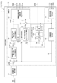
- FIG. 1 is a diagram showing a configuration of a motor unit including a motor drive control device according to a first embodiment
- 2 is a diagram showing a functional block configuration of a control circuit in the motor drive control device according to the first embodiment
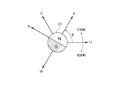
- FIG. FIG. 2 is a diagram showing the relationship between a three-phase fixed coordinate system and a two-phase rotating coordinate system.
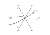
- FIG. 2 is a diagram showing current vectors in a two-phase rotating coordinate system.
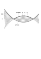
- FIG. 4 is a diagram showing the relationship between the phase current of each phase of the motor and the q-axis current.
- FIG. 4 is a diagram showing an example of a positive q-axis current and a phase current.
- FIG. 4 is a diagram showing an example of a negative q-axis current and a phase current.
- FIG. 13 is a diagram showing the correspondence relationship between sectors and phase currents that are candidates for peak values.
- 4 is a diagram illustrating an example of the configuration of a peak value detection unit according to the first embodiment
- FIG. 10 is a diagram for explaining a delay in current with respect to a voltage applied to a coil of a motor.
- FIG. 11 is a diagram for explaining a method of calculating a lead-angle value.
- FIG. 11 is a diagram showing an example of a table that associates advance angle values with each combination of rotation speed and q-axis current, as correspondence information
- 5 is a flowchart showing an example of the flow of a process for generating a drive control signal by the motor drive control device according to the first embodiment.
- FIG. 10 is a flowchart showing an example of a flow of a calculation process (step S5) of a q-axis current according to the first embodiment.
- FIG. 11 is a diagram showing a functional block configuration of a control circuit in a motor drive control device according to a second embodiment. 10 is a diagram for explaining a deviation of a current vector caused by a deviation of an estimated value from a true value of a rotation angle of a rotor.
- FIG. FIG. 11 is a diagram for explaining an overview of a method for estimating a q-axis current according to a second embodiment.
- FIG. 11 is a diagram showing an example of a correspondence relationship between sectors and phase currents that are candidates for peak values in the second embodiment.
- FIG. 11 is a diagram showing an example of a correspondence relationship between sectors and phase currents that are candidates for peak values in the second embodiment.
- FIG. 11 is a diagram illustrating an example of the configuration of a peak value detection unit according to the second embodiment.
- 13 is a flowchart showing an example of a flow of a calculation process (step S5) of a q-axis current in the second embodiment.
- FIG. 11 is a diagram showing a functional block configuration of a control circuit in a motor drive control device according to a third embodiment.
- FIG. 2 is a diagram showing the relationship between current vectors and voltage vectors in a two-phase rotating coordinate system.
- FIG. 13 is a diagram illustrating an example of the configuration of a peak value detection unit according to the third embodiment.
- FIG. 11 is a diagram for explaining an overview of a method for estimating a q-axis current according to a third embodiment.
- FIG. 13 is a diagram showing an example of a correspondence relationship between sectors and phase currents that are candidates for peak values in the third embodiment.
- FIG. 13 is a diagram showing an example of a correspondence relationship between sectors and phase currents that are candidates for peak values in the third embodiment.
- a motor drive control device (10, 10A, 10B) includes a control circuit (1, 1A, 1B) that outputs a drive control signal (Sd) for driving a motor (3) having coils of multiple phases (Lu, Lv, Lw), and a drive circuit (2) that drives the motor based on the drive control signal output from the control circuit, the drive circuit including an inverter circuit (2a) that drives the coils of the multiple phases based on the drive control signal, and a current detection circuit (2c) that detects currents flowing through the coils of the multiple phases and outputs a current detection signal (Vm) corresponding to the detected current, the control circuit including a drive command acquisition unit (11) that acquires drive command signals (Sc, Sc1) including values indicating a target state of operation of the motor, and a drive command acquisition unit (12) that converts the current detection signal into a signal representing a target state of operation of the motor.
- a drive command acquisition unit (11) that acquires drive command signals (Sc, Sc1) including values indicating a target state of
- the motor includes a q-axis current calculation unit (12, 12A, 12B) that detects, as a peak value (ip), the phase current closest to the q-axis current in the two-phase rotating coordinate system when the d-axis current in the two-phase rotating coordinate system is set to zero, among the phase currents (iu, iv, iw) flowing through the coils of each phase and the phase currents (-iu, -iv, -iw) in which the phase of the phase currents flowing through the coils of each phase is inverted by 180°, based on the rotation angle of the rotor (31) of the motor, and calculates the q-axis current (iq) when the d-axis current is set to zero based on the envelope of the peak value, and a calculation unit (13) that generates the drive control signal by performing a vector control calculation using the q-axis current calculated by the q-axis current calculation unit, the drive command signal, the rotation speed of the rotor of the motor
- the control circuit stores correspondence information (128, 128A_1, 128A_2, 128B_1, 128B_2) in which the range of electrical angle according to the rotation of the rotor is divided into a plurality of sectors (I-VI) in which the phase currents that are candidates for the peak value are associated with each other, and the q-axis current calculation unit detects the phase of a current vector in the two-phase rotating coordinate system based on the rotation angle of the rotor and the current detection signal, identifies the sector to which the phase of the current vector belongs, selects a candidate phase current associated with the identified sector based on the correspondence information, and sets the selected phase current as the peak value.
- correspondence information (128, 128A_1, 128A_2, 128B_1, 128B_2
- the q-axis current calculation unit (12A, 12B) may compare the absolute values of the magnitudes of the multiple candidate phase currents and determine the phase current with the largest absolute value as the peak value.
- the q-axis current calculation unit (12, 12A) may take the rotation angle of the rotor ( ⁇ ) plus ⁇ /2 as the phase of the current vector.
- the q-axis current calculation unit (12B) may detect the phase of the current vector based on the phase ( ⁇ ) of the voltage vector in the two-phase rotating coordinate system, calculated based on the rotation angle of the rotor.
- the q-axis current calculation unit (12, 12A, 12B) may include a peak value detection unit (121, 121A, 121B) that detects the peak value based on the rotation angle of the rotor and the current detection signal, a low-pass filter (122) to which the peak value detected by the peak value detection unit is input, and a multiplication unit (123) that multiplies the value output from the low-pass filter by a predetermined value and outputs the result as the q-axis current.
- the predetermined value may be ⁇ /3.
- the sector may be a range obtained by dividing the electrical angle range from 0° to 360° in increments of 60°.
- a motor drive control method includes a first step (S1) of acquiring a drive command signal including a value indicating a target state of operation of a motor having coils of multiple phases; a second step (S4) of detecting currents flowing through the coils of the multiple phases; a third step (S5) of detecting, based on the currents detected in the second step and the rotation angle of the rotor of the motor, a phase current closest to a q-axis current in a two-phase rotating coordinate system when the d-axis current in the two-phase rotating coordinate system is set to zero, among the phase currents flowing through the coils of each phase and the phase currents obtained by inverting the phase of the phase currents flowing through the coils of each phase by 180°, and calculating, based on the envelope of the peak value, the q-axis current when the d-axis current is set to zero; and a fourth step (S6 to S9) of generating a drive control signal for driving
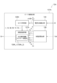
- FIG. 1 is a diagram showing the configuration of a motor unit 100 including a motor drive control device 10 according to a first embodiment.
- the motor unit 100 includes a motor 3 and a motor drive control device 10 that controls the rotation of the motor 3.
- the motor unit 100 can be applied to various devices that use a motor as a drive source, such as a fan.
- Motor 3 is, for example, a permanent magnet synchronous motor (PMSM).
- motor 3 is, for example, a surface magnet synchronous motor (SPMSM) having three-phase coils Lu, Lv, and Lw. Coils Lu, Lv, and Lw are, for example, connected together in a Y-connection.
- PMSM permanent magnet synchronous motor
- SPMSM surface magnet synchronous motor
- the motor drive control device 10 applies a sine wave drive signal to the motor 3, causing periodic sine wave phase currents to flow through the three-phase coils Lu, Lv, and Lw of the motor 3, thereby rotating the rotor 31 of the motor 3 (see Figure 3).
- the motor drive control device 10 includes a control circuit 1 and a drive circuit 2 . Note that the components of the motor drive control device 10 shown in FIG. 1 are only a portion of the whole, and the motor drive control device 10 may have other components in addition to those shown in FIG.
- the drive circuit 2 drives the motor 3 based on a drive control signal Sd output from the control circuit 1, which will be described later.
- the drive circuit 2 includes, for example, an inverter circuit 2a, a pre-drive circuit 2b, and a current detection circuit 2c.
- the inverter circuit 2a is disposed between the DC power supply Vcc and ground potential, and drives the multiple-phase coils Lu, Lv, and Lw of the motor 3 as a load based on the input drive control signal Sd.
- the inverter circuit 2a has three switching legs, each including two drive transistors connected in series, and drives the motor 3 as a load by alternately turning the two drive transistors on and off (switching operation) based on the input drive control signal Sd.
- the inverter circuit 2a has switching legs corresponding to the U-phase, V-phase, and W-phase of the motor 3. As shown in FIG. 1, the switching legs corresponding to each phase have two drive transistors Q1 and Q2, Q3 and Q4, and Q5 and Q6 connected in series between the DC power supply Vcc and the ground potential via the current detection circuit 2c.
- the driving transistors Q1, Q3, and Q5 are, for example, N-channel MOSFETs
- the driving transistors Q2, Q4, and Q6 are, for example, N-channel MOSFETs.
- the driving transistors Q1 to Q6 may be other types of transistors, such as IGBTs (Insulated Gate Bipolar Transistors).
- the switching leg corresponding to the U phase has drive transistors Q1 and Q2 connected in series.
- the point where drive transistors Q1 and Q2 are commonly connected is connected to one end of coil Lu as a load.
- the switching leg corresponding to the V phase has drive transistors Q3 and Q4 connected in series.
- the point where drive transistors Q3 and Q4 are commonly connected is connected to one end of coil Lv as a load.
- the switching leg corresponding to the W phase has drive transistors Q5 and Q6 connected in series.
- the point where drive transistors Q5 and Q6 are commonly connected is connected to one end of coil Lw as a load.
- the pre-drive circuit 2b generates a drive signal for driving the inverter circuit 2a based on the drive control signal Sd output from the control circuit 1.
- the drive control signal Sd is a signal for controlling the drive of the motor 3, and is, for example, a PWM (Pulse Width Modulation) signal.
- the drive control signal Sd is a signal for switching the current conduction pattern of the coils Lu, Lv, and Lw of the motor 3, which is determined by the on/off state of each drive transistor that constitutes the inverter circuit 2a.
- the drive control signal Sd includes six types of PWM signals corresponding to each drive transistor Q1 to Q6 of the inverter circuit 2a.
- the pre-drive circuit 2b generates six types of drive signals Vuh, Vul, Vvh, Vvl, Vwh, and Vwl that can supply sufficient power to drive the control electrodes (gate electrodes) of the drive transistors Q1 to Q6 of the inverter circuit 2a, based on six types of PWM signals as the drive control signals Sd supplied from the control circuit 1.
- These drive signals Vuh, Vul, Vvh, Vvl, Vwh, and Vwl are input to the control electrodes (gate electrodes) of the drive transistors Q1 to Q6 of the inverter circuit 2a, causing each of the drive transistors Q1 to Q6 to perform an on/off operation (switching operation).
- the drive transistors Q1, Q3, and Q5 of the upper arm and the drive transistors Q2, Q4, and Q6 of the lower arm of the switching leg corresponding to each phase alternately perform an on/off operation.
- power is supplied from the DC power supply Vcc to each phase of the motor 3, causing the motor 3 to rotate.
- the drive circuit 2 does not need to have the pre-drive circuit 2b.
- the current detection circuit 2c is a circuit for detecting the current flowing through the coils Lu, Lv, and Lw of the multiple phases of the motor 3.
- the current detection circuit 2c detects the currents (phase currents) iu, iv, and iw flowing through the coils Lu, Lv, and Lw of each phase, and outputs a current detection signal Vm that corresponds to the detected current.
- the current detection circuit 2c is, for example, connected in series with the inverter circuit 2a, and outputs a signal indicating the phase currents iu, iv, and iw of the coils Lu, Lv, and Lw as the current detection signal Vm.
- the current detection circuit 2c includes, for example, at least one resistor (shunt resistor) as a current detection element.
- the shunt resistor is, for example, connected in series with the inverter circuit 2a between the DC power supply Vcc and the ground potential (one shunt system).
- the shunt resistor as the current detection circuit 2c is, for example, connected to the negative side (ground side) of the inverter circuit 2a.
- the current detection circuit 2c converts the phase currents iu, iv, iw of the coils Lu, Lv, Lw of the motor 3 into a voltage using the resistor, and inputs the voltage to the control circuit 1 as a current detection signal Vm.
- the current detection signal Vm becomes a signal indicating the phase currents iu, iv, iw of the coils Lu, Lv, Lw.
- the position sensor 4 is a device for detecting the rotational position of the rotor 31 of the motor 3.
- the position sensor 4 outputs a signal corresponding to the rotational position of the rotor 31.
- the position sensor 4 is, for example, a Hall element.
- FIG. 1 shows a case where Hall elements are provided as position sensors 4u, 4v, and 4w for each of the U-phase, V-phase, and W-phase of the motor 3.
- the position sensors 4u, 4v, and 4w are also referred to as "Hall elements 4u, 4v, and 4w.”
- the Hall elements 4u, 4v, 4w are arranged around the rotor 31 of the motor 3 at approximately equal intervals (e.g., 120 degrees between adjacent elements).
- the Hall elements 4u, 4v, 4w each detect the magnetic poles of the rotor 31 and output Hall signals whose voltage changes according to the rotation of the rotor 31 as rotational position detection signals Hu, Hv, Hw.
- the rotational position detection signals Hu, Hv, Hw are input to the control circuit 1.
- control circuit 1 may be configured to input another signal corresponding to the rotational position of the rotor 31 of the motor 3 as a rotational position detection signal instead of such a Hall signal.
- a rotational position detection signal instead of such a Hall signal.
- an encoder or resolver may be provided and its detection signal may be input to the control circuit 1.
- the control circuit 1 generates a drive control signal Sd for driving the motor 3 based on a drive command signal Sc that is input from the outside and indicates the target state of the operation of the motor 3, and controls the driving of the motor 3. Specifically, the control circuit 1 obtains information such as the rotation speed and torque of the rotor 31 of the motor 3 based on the current detection signal Vm from the current detection circuit 2c and the rotation position detection signals Hu, Hv, Hw from the position sensors 4u, 4v, 4w to monitor the rotation state of the motor 3, and generates a drive control signal Sd to provide to the drive circuit 2 so that the motor 3 is in the operating state specified by the drive command signal Sc.
- control circuit 1 is a program processing device (e.g., a microcontroller) having a configuration in which a processor such as a CPU, various storage devices such as RAM and ROM, and peripheral circuits such as a counter (timer), an A/D conversion circuit, a D/A conversion circuit, a clock generation circuit, and an input/output I/F circuit are connected to each other via a bus or dedicated lines.
- a processor such as a CPU
- various storage devices such as RAM and ROM
- peripheral circuits such as a counter (timer), an A/D conversion circuit, a D/A conversion circuit, a clock generation circuit, and an input/output I/F circuit are connected to each other via a bus or dedicated lines.
- control circuit 1 and the drive circuit 2 may each be packaged as separate integrated circuit devices, or at least a portion of the control circuit 1 and at least a portion of the drive circuit 2 may be packaged as a single integrated circuit device (IC).
- IC integrated circuit device
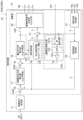
- FIG. 2 is a diagram showing the functional block configuration of the control circuit 1 in the motor drive control device 10 according to the first embodiment.
- control circuit 1 has a drive command acquisition unit 11, a q-axis current calculation unit 12, and a calculation unit 13 as functional blocks for generating the drive control signal Sd.
- These functional blocks are realized, for example, by a processor in a program processing device serving as the control circuit 1, which executes various arithmetic operations according to a program stored in memory and controls peripheral circuits such as a counter and an A/D conversion circuit. At least some of these functional blocks may be realized by a dedicated hardware logic circuit.
- the drive command acquisition unit 11 receives a drive command signal Sc from the outside and analyzes the received drive command signal Sc to acquire a value that specifies the target operating state of the motor 3 specified by the drive command signal Sc.
- the drive command signal Sc includes a value indicating a target state for the operation of the motor 3.
- the drive command signal Sc is, for example, a signal output from a higher-level device for controlling the motor unit 100, which is provided outside the motor drive control device 10.
- the drive command signal Sc is, for example, a speed command signal Sc1 that specifies the rotation speed of the rotor of the motor 3.
- the drive command signal Sc includes a value ⁇ ref of the target rotation speed (target rotation speed) of the rotor of the motor 3.
- the drive command signal Sc will be described as being the speed command signal Sc1.
- the speed command signal Sc1 is, for example, a PWM signal having a duty ratio corresponding to the specified target rotation speed ⁇ ref.
- the drive command acquisition unit 11 measures, for example, the duty ratio of the PWM signal serving as the speed command signal Sc1, and outputs a rotation speed corresponding to the measured duty ratio as the target rotation speed ⁇ ref.
- the q-axis current calculation unit 12 is a functional unit that calculates the q-axis current in a two-phase rotating coordinate system based on the phase currents iu, iv, and iw of the coils Lu, Lv, and Lw of the motor 3.
- the q-axis current calculation unit 12 calculates the q-axis current using a simple method to reduce the computational load in conventional motor vector control, and generates the drive control signal Sd. The method for calculating the q-axis current is explained below.
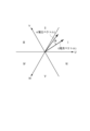
- Figure 3 shows the relationship between a three-phase (U, V, W) fixed coordinate system and a two-phase (d, q) rotating coordinate system.
- the UVW axes are a three-phase fixed coordinate system
- the dq axes are a two-phase rotating coordinate system.
- the d-axis in the two-phase (d, q) rotating coordinate system is set to the magnetic flux direction (N pole direction) of the permanent magnet that serves as the rotor
- the q-axis is set to the direction 90 degrees ( ⁇ /2) ahead of the d-axis in the positive direction.
- the rotation angle ⁇ of the rotor 31 measured by the rotation angle acquisition unit 14 is the rotation angle of the d-axis, for example, the angle between the U-axis and the d-axis in a three-phase (U, V, W) fixed coordinate system.
- Te is the generated torque
- P is the number of pole pairs
- ⁇ is the magnetic flux of the permanent magnet (rotor)
- Ld is the d-axis inductance
- Lq is the q-axis inductance
- id is the d-axis current
- iq is the q-axis current
- ⁇ iq is the magnet torque
- "(Ld-Lq)idiq” is the reluctance torque.
- motor 3 is a surface permanent magnet synchronous motor (SPMSM)
- SPMSM surface permanent magnet synchronous motor
- Figure 4 shows the current vector i in a two-phase (d, q) rotating coordinate system.
- the current vector i in the two-phase (d, q) rotating coordinate system is composed of a d-axis current component and a q-axis current component.
- the current vector i coincides with the q-axis current vector.
- the q-axis current is positive.
- the q-axis current becomes negative. That is, the phase of the current vector during reverse rotation is shifted by 180° ( ⁇ ) from the current vector during forward rotation. In other words, when rotating the rotor 31 in the reverse direction, the q-axis current needs to be made negative. Also, even when the q-axis current is controlled to zero or very small, the q-axis current may become negative due to the effects of noise caused by voltage fluctuations, load fluctuations, etc.
- cases where the q-axis current is controlled to zero or very small include, for example, control to start a motor that is spinning freely without braking (windmill start), or when rotating the motor at a very slow speed.
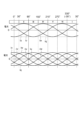
- FIG. 5 is a diagram showing the relationship between the phase currents iu, iv, iw of the motor 3 and the q-axis current.
- the horizontal axis represents time
- the vertical axis represents current.
- phase currents iu, iv, and iw of the coils of each phase of the motor 3 have sinusoidal waveforms that are, for example, out of phase with each other by 120 degrees.
- the d-axis current id is set to zero.
- the q-axis current iq approximately matches the amplitude of the phase currents iu, iv, and iw of the coils Lu, Lv, and Lw of each phase of the motor 3.
- the q-axis current when the rotor 31 is rotating in the forward direction, the q-axis current is positive. In this case, as shown in FIG. 5, the q-axis current is approximately equal to the positive amplitude of the phase currents iu, iv, iw of the coils Lu, Lv, Lw of each phase of the motor 3. On the other hand, when the rotor 31 is rotated in the reverse direction, the q-axis current is negative. In this case, as shown in FIG. 5, the q-axis current is approximately equal to the negative amplitude, not the positive amplitude, of the phase currents iu, iv, iw of the coils Lu, Lv, Lw of each phase of the motor 3.
- the motor drive control device 10 estimates the q-axis current when the d-axis current id is zero based on the phase currents iu, iv, iw flowing through the coils Lu, Lv, Lw of each phase and the phase currents -iu, -iv, -iw obtained by inverting the polarity of the phase currents iu, iv, iw (multiplying them by -1).
- Figure 6 shows an example of a positive q-axis current and phase current.
- the upper part of Figure 6 shows "sectors," which are ranges obtained by dividing the electrical angle range from 0° to 360° into multiple ranges.
- the middle part of Figure 6 shows the phase currents iu, iv, iw of each phase, and the phase currents -iu, -iv, -iw obtained by inverting the phase of the phase currents iu, iv, iw by 180° (multiplying them by -1).
- the lower part of Figure 6 shows the positive q-axis current iq, and an envelope curve showing the temporal change in peak value ip, where ip is the phase current closest to the q-axis current when the d-axis current is set to zero among the phase currents flowing through the coils Lu, Lv, Lw of multiple phases.
- the horizontal axis represents the electrical angle
- the vertical axis represents the current.
- phase current closest to the q-axis current when the d-axis current is set to zero switches every 60° of electrical angle.
- the phase current iu is closest to the q-axis current iq.
- the phase current -iw is closest to the q-axis current iq.
- the phase current iv is closest to the q-axis current iq.
- the phase current -iu is closest to the q-axis current iq.
- phase current iw is closest to the q-axis current iq.
- phase current -iv is closest to the q-axis current iq.
- phase currents iu, iv, iw, -iu, -iv, -iw is closest to the q-axis current (positive) when the d-axis current is zero.
- Figure 7 shows an example of the negative q-axis current and phase current.
- the upper part of Figure 7 shows "sectors," which are ranges obtained by dividing the electrical angle range from 0° to 360° into multiple ranges.
- the middle part of Figure 7 shows phase currents iu, iv, and iw.
- the lower part of Figure 7 shows phase currents iu, iv, and iw, phase currents -iu, -iv, and -iw with the polarity of each phase current reversed, and the q-axis current iq.
- the horizontal axis represents the electrical angle
- the vertical axis represents the current.
- phase of current vector i when the q-axis current is negative is inverted by 180° from the phase of current vector i when the q-axis current is positive.
- phase of each phase current when the q-axis current is negative is inverted by 180° from the phase of each phase current when the q-axis current is positive. Therefore, as shown in Figure 7, in each sector I-VI, the phase currents that are candidates for the negative q-axis current are the same as the phase currents that are candidates for the positive q-axis current.
- the phase current iu is closest to the q-axis current iq.
- the phase current -iw is closest to the q-axis current iq.
- the phase current iv is closest to the q-axis current iq.
- the phase current -iu is closest to the q-axis current iq.
- phase current iw is closest to the q-axis current iq.
- phase current -iv is closest to the q-axis current iq.
- the q-axis current calculation unit 12 detects, based on the current detection signal Vm and the rotation angle of the rotor 31 of the motor 3, the phase currents iu, iv, iw flowing through the coils Lu, Lv, Lw of each phase, and the phase currents -iu, -iv, -iw obtained by inverting the phases of the phase currents iu, iv, iw by 180°, as the peak value ip, which is the phase current closest to the q-axis current when the d-axis current is set to zero, and calculates, based on the envelope of the peak value ip, the q-axis current in the two-phase rotating coordinate system when the d-axis current in the two-phase rotating coordinate system is set to zero.
- the q-axis current calculation unit 12 may include a peak value detection unit 121, a low-pass filter (LPF) 122, and a multiplication unit 123.
- LPF low-pass filter
- the peak value detection unit 121, the low-pass filter 122, and some or all of the multiplication unit 123 may be realized by program processing using a program processing device as the control circuit 1, or may be realized by a dedicated hardware circuit.
- the peak value detection unit 121 detects, based on the current detection signal Vm and the rotation angle of the rotor 31 of the motor 3, the phase current iu, iv, iw, -iu, -iv, -iw that is closest to the q-axis current when the d-axis current is set to zero, as the peak value ip.
- the phase current that is a candidate for the q-axis current i.e., the phase current that is closest to the q-axis current when the d-axis current is set to zero, switches every 60° of electrical angle (see Figures 6 and 7). Therefore, in the first embodiment, the range of electrical angles (0° to 360°) corresponding to the rotation of the rotor 31 is divided into multiple ranges, each of which is a "sector," and each sector is assigned a phase current that is a candidate for the peak value ip (q-axis current).
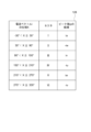
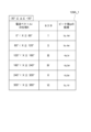
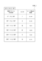
- Figure 8 shows the correspondence between sectors and phase currents that are candidates for the peak value ip.
- phase currents iu, iv, iw, -iu, -iv, -iw is assigned as a candidate phase current for the peak value ip.
- the range of electrical angle X -30° ⁇ X ⁇ 30° is set as sector I, and the phase current iu closest to the q-axis current in sector I is set as a candidate for the peak value ip in sector I.
- the range of electrical angle X 30° ⁇ X ⁇ 90° is set as sector II, and the phase current -iw closest to the q-axis current in sector II is set as a candidate for the peak value ip in sector II.
- the range of electrical angle X 90° ⁇ X ⁇ 150° is set as sector III, and the phase current iv closest to the q-axis current in sector III is set as a candidate for the peak value ip in sector III.
- the range of electrical angle X of 150° ⁇ X ⁇ 210° is defined as sector IV, and the phase current -iu in sector IV that is closest to the q-axis current is defined as a candidate for the peak value ip in sector IV.
- the range of electrical angle X of 210° ⁇ X ⁇ 270° is defined as sector V, and the phase current iw in sector V that is closest to the q-axis current is defined as a candidate for the peak value ip in sector V.
- the range of electrical angle X of 270° ⁇ X ⁇ 330° is defined as sector VI, and the phase current -iv in sector VI that is closest to the q-axis current is defined as a candidate for the peak value ip in sector VI.
- the peak value detection unit 121 detects the phase of the current vector i in a two-phase (d, q) rotating coordinate system based on the rotation angle of the rotor 31 and the current detection signal Vm, identifies the sector to which the phase of the current vector i belongs, and outputs the phase current associated with the identified sector as a peak value ip.
- the peak value detection unit 121 has, for example, a current phase detection unit 124, a sector identification unit 125, a phase current calculation unit 126, and a phase current selection unit 127 as functional blocks for realizing the above processing.
- FIG. 9 is a diagram showing an example of the configuration of the peak value detection unit 121 according to the first embodiment.
- the current phase detection unit 124 detects the phase of the current vector i in a two-phase rotating coordinate system. For example, the current phase detection unit 124 detects the phase of the current vector i based on the rotation angle ⁇ of the rotor 31.
- the current vector i when the d-axis current is set to zero coincides with the q-axis current.
- the current phase detection unit 124 therefore calculates the rotation angle ( ⁇ + ⁇ /2) by adding " ⁇ /2" to the rotation angle ⁇ of the rotor 31 acquired by the rotation angle acquisition unit 14 described below, as the phase of the current vector i. For example, the current phase detection unit 124 calculates the phase of the current vector i for each control period (PWM period) of the motor.
- the phase current calculation unit 126 calculates the phase current based on the current detection signal Vm. For example, in the case of the one-shunt method described above in which one shunt resistor is connected in series to the inverter circuit to detect the current of the motor 3, the path through which the current flows changes depending on which of the drive transistors Q1 to Q6 are turned on during the motor control period (PWM period), and the phase current indicated by the current detection signal Vm switches as the path changes.
- the phase current calculation unit 126 therefore calculates the phase currents iu, iv, and iw from the current detection signal Vm in accordance with the on/off timing of the drive transistors Q1 to Q6 of the inverter circuit, for each control period of the motor 3, using, for example, a known one-shunt type current detection method. Furthermore, the phase current calculation unit 126 multiplies the phase currents iu, iv, and iw by "-1" to calculate the phase currents -iu, -iv, and -iw.
- the sector identification unit 125 identifies the sector to which the phase of the current vector i in the two-phase rotating coordinate system detected by the current phase detection unit 124 belongs. For example, as shown in Figures 6 and 7, if the range of electrical angles from 0 to 360° is divided into six sectors I to VI, the sector identification unit 125 identifies which sector I to VI the phase of the current vector i belongs to. For example, the sector identification unit 125 identifies the sector to which the phase ( ⁇ + ⁇ /2) of the current vector i belongs for each control period of the motor 3, and outputs information on the identified sector.
- the phase current selection unit 127 selects one phase current from the multiple phase currents based on the information of the sector to which the phase of the current vector i belongs, and outputs it as the peak value ip. For example, the phase current selection unit 127 selects the phase current that is a candidate for the peak value ip (q-axis current) using correspondence information 128 that indicates the correspondence between sectors and phase currents that are candidates for the peak value ip, as shown in FIG. 8.
- the correspondence information 128 is, for example, a table in which sectors are associated with phase currents that are candidates for the peak value ip.
- the correspondence information 128 is, for example, stored in advance in a storage device (for example, a non-volatile storage device) in the control circuit 1.
- a storage device for example, a non-volatile storage device
- the phase current selection unit 127 reads the correspondence information 128 from the storage device.
- the phase current selection unit 127 uses the sector to which the phase of the current vector i identified by the sector identification unit 125 belongs as an argument, and reads out the phase current corresponding to the argument from the correspondence information 128.
- the phase current selection unit 127 outputs the read phase current as a peak value ip.
- the phase current selection unit 127 selects the phase current -iw and outputs the phase current -iw as the peak value ip.
- the phase current selection unit 127 outputs the peak value ip for each motor control period.
- the envelope of the peak value ip whose magnitude changes over time, is output from the phase current selection unit 127.
- the envelope of the peak value ip (hereinafter also referred to as the "peak value ip signal") changes (oscillates) in magnitude based on the amplitude of the three-phase AC. Therefore, the low-pass filter 122 removes high-frequency components contained in the peak value ip signal.
- the low-pass filter 122 receives the peak value ip (peak value ip signal) output from the peak value detection unit 121 (phase current selection unit 127).
- the low-pass filter 122 removes high-frequency components from the input peak value ip signal, and outputs a signal obtained by smoothing the peak value ip signal (hereinafter also referred to as the "average value of the peak value ip").
- the average value of the peak value ip output from the low-pass filter 122 is smaller than the q-axis current. Therefore, the multiplier 123 multiplies the signal output from the low-pass filter 122 (average value of the peak value ip) by a predetermined value. For example, the average value of the peak value ip is 3/ ⁇ times smaller than the q-axis current. Therefore, the multiplier 123 multiplies the value output from the low-pass filter 122 by " ⁇ /3", for example. This makes it possible to obtain an approximation (estimated value) of the q-axis current when the d-axis current id is set to zero. The multiplier 123 outputs the approximation of the q-axis current calculated as described above as the "q-axis current iq".
- the above-mentioned predetermined value is not limited to the above-mentioned " ⁇ /3", but may be set appropriately so that an appropriate approximation of the q-axis current can be calculated from the value output from the low-pass filter 122.
- the calculation unit 13 generates a drive control signal Sd by performing a vector control calculation using the q-axis current iq calculated by the q-axis current calculation unit 12, the drive command signal Sc (speed command signal Sc1) acquired by the drive command acquisition unit 11, the rotational speed ⁇ of the rotor 31 of the motor 3, and the rotational angle ⁇ of the rotor 31.
- the calculation unit 13 has a rotation angle acquisition unit 14, a rotation speed acquisition unit 15, error calculation units 16 and 18, a q-axis current command value calculation unit 17, a voltage command value calculation unit 19, a lead angle control unit 20, an adder unit 21, and a drive control signal generation unit 22.
- the rotation angle acquisition unit 14 is a functional unit that acquires the measured value of the rotation angle of the rotor 31 of the motor 3.
- the rotation angle acquisition unit 14 calculates the rotation angle (rotation position) ⁇ of the rotor 31 of the motor 3 by a known calculation method, for example, based on the rotation position detection signals Hu, Hv, and Hw output from the position sensors 4u, 4v, and 4w.
- the rotational speed acquisition unit 15 is a functional unit that acquires a measured value of the rotational speed of the rotor 31 of the motor 3.
- the rotational speed acquisition unit 15 calculates the rotational speed ⁇ of the rotor 31 of the motor 3 by a known calculation method based on the rotational position detection signals Hu, Hv, and Hw output from the position sensors 4u, 4v, and 4w.
- the rotational speed acquisition unit 15 calculates the rotational speed ⁇ of the rotor 31 of the motor 3 based on the rotation angle ⁇ calculated by the rotational angle acquisition unit 14.
- the error calculation unit 16 is a functional unit that calculates the difference ( ⁇ ref- ⁇ ) between the target rotation speed ⁇ ref output from the drive command acquisition unit 11 and the actual rotation speed ⁇ of the motor 3 acquired by the rotation speed acquisition unit 15.
- the q-axis current command value calculation unit 17 is a functional unit that calculates the q-axis current command value iqref so that the difference between the target rotation speed ⁇ ref and the rotation speed ⁇ of the motor 3 becomes small.
- the q-axis current command value calculation unit 17 calculates the q-axis current command value iqref as the control amount of the motor 3, for example, by a PI control calculation so that the error ( ⁇ ref- ⁇ ) calculated by the error calculation unit 16 becomes zero.
- the error calculation unit 18 is a functional unit that calculates the difference (iqref-iq) between the q-axis current command value iqref calculated by the q-axis current command value calculation unit 17 and the q-axis current iq calculated by the q-axis current calculation unit 12.
- the voltage command value calculation unit 19 is a functional unit that calculates a voltage command value vref in a two-phase (d, q) rotating coordinate system so that the difference between the q-axis current command value iqref calculated by the q-axis current command value calculation unit 17 and the q-axis current iq calculated by the q-axis current calculation unit 12 becomes small.
- the voltage command value calculation unit 19 calculates the voltage command value vref as a control amount for the motor 3, for example, by a PI control calculation so that the error (iqref-iq) calculated by the error calculation unit 18 becomes zero.
- the advance angle control unit 20 is a functional unit that performs advance angle control of the motor 3 .
- the lead-angle control unit 20 calculates the phase lead angle (lead-angle value ⁇ ) of the applied voltage (phase applied voltage) of each coil Lu, Lv, Lw based on the q-axis current iq calculated by the q-axis current calculation unit 12 and the rotational speed ⁇ of the rotor 31 acquired by the rotational speed acquisition unit 15. Specifically, the lead-angle control unit 20 calculates the lead-angle value ⁇ at which the d-axis current id in a two-phase (d, q) rotating coordinate system becomes zero. A method for calculating the lead-angle value ⁇ will be described in detail below.
- FIG. 10 is a diagram for explaining a delay in current with respect to the voltage applied to the coil of a motor.
- the coil current lags in phase with respect to the applied voltage due to the coil inductance. Therefore, in general lead angle control, the phase of the applied voltage is advanced by the amount of phase delay ⁇ of the coil current with respect to the applied voltage, so that the current has the desired phase.
- the lead angle of the applied voltage in this case is called the lead angle value ⁇ .
- the d-axis inductance and q-axis inductance are equal, so when the d-axis current id is zero, the motor's efficiency is maximized.
- the d-axis current id zero, that is, to make the current only the q-axis component, it is sufficient to advance the phase of the applied voltage by the lead angle value ⁇ relative to the q-axis.
- the motor drive control device 10 calculates the lead angle value ⁇ at which the d-axis current id in the rotating coordinate system becomes zero, and generates the drive control signal Sd by performing space vector transformation based on the polar coordinate information represented by the lead angle value ⁇ and the voltage command value vref in the rotating coordinate system.
- FIG. 11 is a diagram for explaining a method of calculating the lead angle value.
- the voltage command value vref vector
- the horizontal axis is the d-axis and the vertical axis is the q-axis.
- d-axis voltage value vd in the two-phase (d, q) rotating coordinate system of a permanent magnet synchronous motor is expressed by the following equation (2).
- the drive of the motor 3 can be controlled so that the d-axis current id becomes zero.
- the lead angle value ⁇ when the d-axis current id is set to zero is expressed by the following formula (5).
- the lead angle control unit 20 calculates the lead angle value ⁇ at which the d-axis current id in the two-phase (d, q) rotating coordinate system becomes zero, based on the q-axis current iq calculated by the q-axis current calculation unit 12 and the rotation speed ⁇ of the rotor 31 acquired by the rotation speed acquisition unit 15.
- the lead angle control unit 20 calculates the angle (lead angle value) ⁇ of the vector of the voltage command value vref with respect to the q axis when the d-axis component of the vector of the voltage command value vref matches the d-axis voltage value vd when the d-axis current id is zero.
- the rotation angle ⁇ of the rotor 31 of the motor 3 is the rotation angle of the d-axis.
- the lead angle value ⁇ is the angle of the vector of the voltage command value vref with respect to the q-axis. Therefore, the lead angle value ⁇ based on the d-axis is " ⁇ + ⁇ /2".
- the lead-angle control unit 20 calculates the lead-angle value ⁇ using correspondence information 201 that indicates the correspondence between the rotation speed ⁇ of the rotor 31, the q-axis current iq, and the lead-angle value ⁇ ( ⁇ ).
- correspondence information 201 indicates the correspondence between the rotation speed ⁇ of the rotor 31, the q-axis current iq, and the lead-angle value ⁇ ( ⁇ ).
- the following methods can be exemplified as a method for calculating the lead-angle value ⁇ using the correspondence information 201.
- the lead angle control unit 20 may have a function of the lead angle value ⁇ expressed by equation (5) as the correspondence information 201, and calculate the lead angle value ⁇ based on equation (5).
- the function of the angle ⁇ expressed by equation (5) is stored in advance in a memory in the control circuit 1 as the correspondence information 201.
- the lead angle control unit 20 reads equation (5) as the correspondence information 201 from the memory, and calculates the angle ⁇ at which the d-axis current id becomes zero by substituting the q-axis current iq calculated by the q-axis current calculation unit 12 and the rotation speed ⁇ of the rotor 31 acquired by the rotation speed acquisition unit 15 into equation (5).
- the lead angle control unit 20 then outputs a value obtained by adding ⁇ /2 to the calculated angle ⁇ as the lead angle value ⁇ based on the d-axis.
- the lead angle control unit 20 can use, for example, a value stored in advance in the memory in the control circuit 1 as the q-axis inductance Lq. Also, in the calculation using equation (5) above, the lead angle control unit 20 can use the value calculated by the voltage command value calculation unit 19 as the voltage command value vref.
- the advance angle control unit 20 may calculate the value of the voltage command value vref using the q-axis current iq and the rotation speed ⁇ without obtaining the value of the voltage command value vref from the voltage command value calculation unit 19.
- the lead angle control unit 20 may have a table as the correspondence information 201 in which the lead angle value ⁇ corresponds to each combination of the rotation speed ⁇ and the q-axis current iq, and calculate the lead angle value ⁇ based on the table.
- FIG. 12 shows an example of a table that associates a lead angle value ⁇ with each combination of rotation speed ⁇ and q-axis current iq as the correspondence information 201.
- the q-axis inductance Lq is a fixed value, and the voltage command value vref can be calculated from the q-axis current iq and the rotation speed ⁇ . Therefore, the optimal lead-angle value ⁇ is measured in advance using the rotation speed ⁇ of the rotor 31 and the q-axis current iq as variables. Alternatively, the lead-angle value ⁇ is calculated in advance using the above formula (5). Then, a table is created that associates the lead-angle value ⁇ with each combination of the rotation speed ⁇ and the q-axis current iq as variables, and this is stored in advance in the memory in the control circuit 1 as the correspondence information 201.
- the lead angle control unit 20 uses the q-axis current iq calculated by the q-axis current calculation unit 12 and the rotation speed ⁇ of the rotor 31 acquired by the rotation speed acquisition unit 15 as arguments, references a table as the correspondence information 201, and reads out the lead angle value ⁇ corresponding to the arguments from the table and outputs it.
- the lead angle value ⁇ calculated by the above method is input to the adder 21.
- the drive control signal generating unit 22 is a functional unit that generates a drive control signal Sd based on the angle ⁇ obtained by adding the lead angle value ⁇ and the rotation angle ⁇ of the rotor 31, and the voltage command value vref.
- FIG. 13 is a flowchart showing an example of the flow of the process of generating the drive control signal Sd by the motor drive control device 10 according to the first embodiment.
- control circuit 1 when the control circuit 1 receives a speed command signal Sc1 from a higher-level device, it analyzes the speed command signal Sc1 to obtain information on the target rotation speed ⁇ ref of the motor 3 specified by the speed command signal Sc1 (step S1).
- the control circuit 1 acquires the rotation angle ⁇ of the rotor 31 of the motor 3 (step S2). Specifically, as described above, the rotation angle acquisition unit 14 calculates the rotation angle ⁇ of the rotor 31 of the motor 3 based on the rotation position detection signals Hu, Hv, and Hw output from the Hall elements 4u, 4v, and 4w serving as position sensors.
- the control circuit 1 acquires the rotation speed ⁇ of the motor 3 (step S3). Specifically, as described above, the rotation speed acquisition unit 15 calculates the rotation speed ⁇ of the rotor 31 of the motor 3 based on the rotation angle ⁇ of the rotor 31 calculated in step S2.
- the control circuit 1 detects the phase currents iu, iv, and iw of the coils of each phase of the motor 3 (step S4). Specifically, the current detection circuit 2c outputs a current detection signal Vm according to the coil phase currents iu, iv, and iw using the method described above, and the q-axis current calculation unit 12 acquires the current detection signal Vm.
- control circuit 1 calculates the q-axis current iq (step S5).
- FIG. 14 is a flowchart showing an example of the flow of the calculation process (step S5) of the q-axis current iq in embodiment 1.
- step S5 first, the current phase detection unit 124 detects the phase of the current vector i based on the rotation angle ⁇ of the rotor 31 (step S51). As described above, the current phase detection unit 124 calculates the rotation angle ( ⁇ + ⁇ /2) obtained by adding " ⁇ /2" to the rotation angle ⁇ of the rotor 31 acquired by the rotation angle acquisition unit 14 as the phase of the current vector i.
- the sector identification unit 125 identifies the sector to which the phase ( ⁇ + ⁇ /2) of the current vector i belongs (step S52).
- the sector identification unit 125 identifies which of the six sectors I to VI shown in Figures 6 and 7 the phase of the current vector i belongs to.
- the phase current selection unit 127 selects one phase current that is a candidate for the peak value ip from the multiple phase currents (step S53). Specifically, as described above, the phase current selection unit 127 reads out the candidate phase current from the correspondence information 128 using the sector to which the phase of the current vector i identified in step S52 belongs as an argument.
- the phase current selection unit 127 outputs the candidate phase current selected in step S53 as a peak value ip (step S54). Specifically, the phase current selection unit 127 outputs the candidate phase current from among the multiple phase currents output from the phase current calculation unit 126 as a peak value ip.
- the low-pass filter 122 smoothes the signal (envelope) of the peak value ip output from the phase current selection unit 127 (step S55).
- the multiplication unit 123 multiplies the signal smoothed by the low-pass filter 122 (average value of the peak value ip) by a predetermined value (step S56). Specifically, as described above, the multiplication unit 123 multiplies the average value of the peak value ip output from the low-pass filter 122 by " ⁇ /3". Then, the multiplication unit 123 outputs the value obtained by multiplying the average value of the peak value ip by the predetermined value as the q-axis current iq (step S57).
- step S6 the control circuit 1 calculates the q-axis current command value iqref (step S6). Specifically, as described above, the error calculation unit 16 calculates the difference between the target rotation speed ⁇ ref and the actual rotation speed ⁇ of the motor 3, and the q-axis current command value calculation unit 17 calculates the q-axis current command value iqref by performing a PI control calculation so that the difference calculated by the error calculation unit 16 becomes zero.
- the control circuit 1 calculates a voltage command value vref in the two-phase (d, q) rotating coordinate system so that the difference between the q-axis current command value iqref calculated in step S6 and the q-axis current iq calculated in step S5 becomes small (step S7).
- the error calculation unit 18 calculates the difference between the q-axis current command value iqref and the actual q-axis current iq of the motor 3, and the voltage command value calculation unit 19 calculates the voltage command value vref by performing a PI control calculation so that the difference calculated by the error calculation unit 18 becomes zero.
- control circuit 1 calculates the lead angle value ⁇ at which the d-axis current id becomes zero based on the q-axis current iq calculated in step S5 and the rotation speed ⁇ of the rotor 31 acquired in step S3 (step S8).
- the lead angle control unit 20 calculates the lead angle value ⁇ by the above-mentioned method using the correspondence information 201.
- the control circuit 1 generates a drive control signal Sd based on the angle ⁇ calculated by adding the lead angle ⁇ calculated in step S8 and the rotation angle ⁇ of the rotor 31, and the voltage command value vref calculated in step S7 (step S9).
- the drive control signal Sd generated by the above processing procedure is supplied to the drive circuit 2. Based on the input drive control signal Sd, the drive circuit 2 controls the energization of the coil of the motor 3 using the method described above. As a result, the motor 3 is controlled to rotate at the target rotation speed ⁇ ref specified by the speed command signal Sc1.
- the control circuit 1 detects one of the phase currents iu, iv, iw flowing through the coils Lu, Lv, Lw of each phase and the phase currents -iu, -iv, -iw obtained by inverting the phase of the phase currents iu, iv, iw by 180° as a peak value ip, calculates the q-axis current when the d-axis current in the two-phase rotating coordinate system is set to zero based on the envelope of the peak value ip, and generates the drive control signal Sd by performing vector control calculations.
- the q-axis current can be appropriately estimated even when the q-axis current is negative or zero or a very small value. This makes it possible to stably perform, for example, control to rotate the rotor 31 of the motor 3 in reverse, control to start a motor that is idling without applying the brakes (windmill start), and control to rotate the motor at a very low speed.
- the control circuit 1 also stores correspondence information 128 in which the phase currents that are candidates for the peak value ip are associated with each of the sectors into which the range of electrical angle according to the rotation of the rotor 31 is divided.
- the q-axis current calculation unit 12 detects the phase of the current vector i in a two-phase (d, q) rotating coordinate system based on the rotation angle of the rotor 31 and the current detection signal Vm, and identifies the sector to which the phase of the current vector i belongs. Based on the correspondence information 128, the q-axis current calculation unit 12 selects a candidate phase current that is associated with the identified sector, and sets the selected phase current as the peak value ip.
- the phase current that is closest to the q-axis current is determined according to the electrical angle, so by preparing correspondence information 128 in advance that associates the phase currents that are candidates for the peak value ip (q-axis current) with each sector, and reading out the candidate phase currents that are associated with the sector to which the phase of the current vector i belongs from the correspondence information 128, the phase current that is closest to the q-axis current can be easily determined. This makes it possible to further reduce the calculation load on the control circuit 1.
- the motor drive control device 10 can appropriately calculate the q-axis current while reducing the computational load.
- the control circuit 1 drives the motor 3 by performing advance angle control so that the d-axis current id becomes zero. This makes it possible to reduce the computational load compared to the conventional method of calculating the d-axis current id by coordinate transformation and performing vector control calculations so that the calculated d-axis current id becomes zero. This makes it possible to further reduce the processing power required for the program processing device serving as the control circuit 1, making it possible to provide a motor drive control device 10 with lower costs.
- the control circuit 1 calculates the lead-angle value ⁇ ( ⁇ ) for making the d-axis current id zero, it uses the correspondence information 201 indicating the correspondence between the rotation speed ⁇ of the rotor 31, the q-axis current iq, and the lead-angle value ⁇ .
- the correspondence information 201 indicating the correspondence between the rotation speed ⁇ of the rotor 31, the q-axis current iq, and the lead-angle value ⁇ .
- a table that associates the lead-angle value ⁇ for each combination of the rotation speed ⁇ of the rotor 31 and the q-axis current iq is stored in advance in the memory of the control circuit 1 as the correspondence information 201. This makes it possible to calculate the lead-angle value ⁇ without performing complex calculations, making it possible to further reduce the calculation load on the control circuit 1.
- FIG. 15 is a diagram showing a functional block configuration of a control circuit 1A in a motor drive control device 10A according to the second embodiment.
- the motor drive control device 10A and the motor 3 form a motor unit 100A.
- a control circuit 1A according to the second embodiment differs from the control circuit 1 according to the first embodiment in the method of detecting the peak value.
- the phase of the current vector i can be calculated based on the rotation angle ⁇ of the rotor 31 of the motor 3.
- an estimated value of the rotation angle of the rotor 31 calculated from the rotation position detection signals Hu, Hv, Hw output from the Hall elements 4u, 4v, 4w serving as position sensors or by a known calculation of position sensorless control may deviate from the true value of the actual rotation angle of the rotor 31.
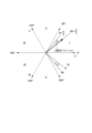
- Figure 16 is a diagram to explain the deviation of the current vector caused by the deviation of the estimated value from the true value of the rotation angle of the rotor 31.
- the true value of the rotation angle of the rotor 31 is " ⁇ tr”
- the estimated value of the rotation angle of the rotor 31 is " ⁇ ”
- the deviation of the estimated value from the true value of the rotation angle of the rotor 31 is " ⁇ ”.
- the peak value detection unit 121A sets multiple phase currents that are candidates for the q-axis current for each sector.
- FIG. 17 is a diagram for explaining an outline of a method for estimating a q-axis current according to the second embodiment.
- the upper part of Fig. 17 shows "sectors," which are ranges obtained by dividing the electrical angle range from 0° to 360° into a plurality of ranges.
- the middle part of Fig. 17 shows phase currents iu, iv, and iw.
- the lower part of Fig. 17 shows phase currents iu, iv, and iw, phase currents -iu, -iv, and -iw that are obtained by inverting the polarities of phase currents iu, iv, and iw, and a q-axis current iq.
- the horizontal axis represents the electrical angle
- the vertical axis represents the current.
- the electrical angle range from 0° to 360° is divided into six sectors I to VI with 0° as the base.
- the range of electrical angle X of 0° ⁇ X ⁇ 60° is sector I
- the range of electrical angle X of 60° ⁇ X ⁇ 120° is sector II
- the range of electrical angle X of 120° ⁇ X ⁇ 180° is sector III
- the range of electrical angle X of 180° ⁇ X ⁇ 240° is sector IV
- the range of electrical angle X of 240° ⁇ X ⁇ 300° is sector V
- the range of electrical angle X of 300° ⁇ X ⁇ 360° is sector VI.
- an error ⁇ may occur between the estimated value ( ⁇ + ⁇ /2) of the phase of current vector i and the true value ( ⁇ tr+ ⁇ /2) of the phase of current vector i.
- the phase current closest to the q-axis current in each sector changes depending on the magnitude of the error ⁇ . For example, when the error ⁇ is in the range of -30° ⁇ +30°, two phase currents can be candidates for the peak value ip (q-axis current) in each sector. When the error ⁇ is in the range of -30° ⁇ +60°, three phase currents can be candidates for the peak value ip (q-axis current) in each sector.
- FIGS. 18A and 18B are diagrams showing an example of the correspondence between sectors and phase currents that are candidates for the peak value ip in embodiment 2.
- FIG. 18A shows correspondence information 128A_1 between sectors and phase currents that are candidates for the peak value ip when the error ⁇ is in the range of -30° ⁇ +30°.
- FIG. 18B shows correspondence information 128A_2 between sectors and phase currents that are candidates for the peak value ip when the error ⁇ is in the range of -30° ⁇ +60°.
- phase current iu and phase current -iw are candidates for the peak value ip.
- phase current iv and phase current -iw are candidates for the peak value ip.
- phase current -iu and phase current iv are candidates for the peak value ip.
- phase current -iu and phase current iw are candidates for the peak value ip.
- phase current -iv and phase current iw are candidates for the peak value ip.
- phase current iu and phase current -iv are candidates for peak value ip.
- phase current iu, phase current -iw, and phase current -iv are candidates for the peak value ip.
- phase current iv, phase current -iw, and phase current iu are candidates for the peak value ip.
- phase current -iu, phase current iv, and phase current -iw are candidates for the peak value ip.
- phase current -iu, phase current iw, and phase current iv are candidates for the peak value ip.
- phase current -iv, phase current iw, and phase current -iu are candidates for the peak value ip.
- phase current iu, phase current -iv, and phase current iw are candidates for peak value ip.
- phase currents that are candidates for the peak value ip there are multiple phase currents that are candidates for the peak value ip, so in the motor drive control device 10A according to the second embodiment, multiple phase currents that are candidates for the peak value are associated with each sector.
- the q-axis current calculation unit 12A compares the absolute values of the magnitudes of the multiple candidate phase currents in each sector, and determines the phase current with the largest absolute value as the peak value.
- FIG. 19 is a diagram showing an example of the configuration of the peak value detection unit 121A according to the second embodiment.
- the sector identification unit 125A identifies the sector to which the phase of the current vector i in the two-phase rotating coordinate system detected by the current phase detection unit 124 belongs. For example, as shown in FIG. 17, if the range of electrical angles from 0 to 360° is divided into six sectors I to VI, the sector identification unit 125A identifies the sector to which the phase ( ⁇ + ⁇ /2) of the current vector i belongs for each control period of the motor 3, and outputs information on the identified sector.
- At least one of the correspondence information 128A_1 shown in FIG. 18A and the correspondence information 128A_2 shown in FIG. 18B is pre-stored in a storage device (e.g., a non-volatile storage device) in the control circuit 1A.
- a storage device e.g., a non-volatile storage device
- the phase current selection unit 127A reads the correspondence information 128A_1 or the correspondence information 128A_2 from the storage device.
- the phase current selection unit 127A refers to the correspondence information 128A_1 or the correspondence information 128A_2 and selects a candidate phase current associated with the sector to which the phase of the current vector i identified by the sector identification unit 125A belongs.
- the phase current selection unit 127A uses the sector to which the phase of the current vector i identified by the sector identification unit 125 belongs as an argument, selects multiple phase currents corresponding to the argument from the correspondence information 128A_1 or the correspondence information 128A_2, compares the absolute values of the selected multiple phase currents, and outputs the phase current with the largest absolute value as the peak value ip.
- the phase current selection unit 127A selects the phase current iv and the phase current -iw, and compares the absolute value of the phase current iv with the absolute value of the phase current -iw.
- phase current selection unit 127A If the absolute value of the phase current iv is greater than the absolute value of the phase current -iw, the phase current selection unit 127A outputs the phase current iv as a peak value ip, and if the absolute value of the phase current -iw is greater than the absolute value of the phase current iv, the phase current selection unit 127A outputs the phase current -iw as a peak value ip.
- the phase current selection unit 127A selects the phase current iv, the phase current -iw, and the phase current iu, and compares the absolute value of the phase current iv, the absolute value of the phase current -iw, and the absolute value of the phase current iu.
- the phase current selection unit 127A selects the phase current with the largest absolute value, and outputs the selected phase current as the peak value ip.
- the phase current selection unit 127A outputs the phase current iv as the peak value ip.
- At least one of the correspondence information 128A_1 and the correspondence information 128A_2 can be stored in advance in the control circuit 1A, taking into consideration the application to which the motor unit 100A is actually applied.
- the correspondence information 128A_1 can be stored in a storage device in the control circuit 1A
- the correspondence information 128A_2 can be stored in a storage device in the control circuit 1A.
- both the correspondence information 128A_1 and 128A_2 can be stored in a storage device in the control circuit 1A, and the phase current selection unit 127A can read one of the correspondence information from the storage device to detect the peak value ip.
- the motor drive control device 10A drives the motor 3 according to the flowchart shown in FIG. 13, as in the first embodiment.
- the process of step S5 differs from the process of step S5 (FIG. 14) in the first embodiment.
- the calculation process of the q-axis current iq (step S5) in the second embodiment will be described below.
- FIG. 20 is a flowchart showing an example of the flow of the calculation process (step S5) of the q-axis current iq in embodiment 2.
- step S5 first, the current phase detection unit 124 detects the phase of the current vector i based on the rotation angle ⁇ of the rotor 31 (step S51). For example, as described above, the current phase detection unit 124 calculates the rotation angle ( ⁇ + ⁇ /2) obtained by adding " ⁇ /2" to the rotation angle ⁇ of the rotor 31 acquired by the rotation angle acquisition unit 14 as the phase of the current vector i.
- the sector identification unit 125A identifies the sector to which the phase of the current vector i belongs (step S52). For example, the sector identification unit 125A identifies which of the six sectors I to VI shown in FIG. 18 the phase of the current vector i belongs to.
- the phase current selection unit 127A selects a phase current that is a candidate for the peak value ip from the multiple phase currents (step S61). Specifically, as described above, the phase current selection unit 127A reads out multiple candidate phase currents from the correspondence information 128A_1 or the correspondence information 128A_2 using the sector to which the phase of the current vector i identified in step S52 belongs as an argument.
- phase current selection unit 127A uses the method described above to compare the absolute values of the multiple candidate phase currents selected in step S61 (step S62). Next, the phase current selection unit 127A selects the phase current with the largest absolute value from the multiple candidate phase currents, and outputs the selected phase current as a peak value ip (step S63).
- step S63 onwards is the same as that in the first embodiment. That is, the low-pass filter 122 smoothes the signal of the peak value ip output from the phase current selection unit 127A (step S55). Next, the multiplication unit 123 multiplies the peak value ip smoothed by the low-pass filter 122 by a predetermined value ( ⁇ /3) (step S56). Then, the multiplication unit 123 outputs the value obtained by multiplying the smoothed peak value ip by the predetermined value as the q-axis current iq (step S57).
- the motor drive control device 10A according to the second embodiment can appropriately calculate the q-axis current while reducing the computational load, similar to the motor drive control device 10 according to the first embodiment.
- the q-axis current calculation unit 12A compares the absolute values of the multiple candidate phase currents and sets the phase current with the largest absolute value as the peak value ip.
- FIG. 21 is a diagram showing a functional block configuration of a control circuit 1B in a motor drive control device 10B according to the third embodiment.
- a control circuit 1B according to the third embodiment differs from the control circuits 1 and 1A according to the first and second embodiments in the method of detecting the phase of a current vector i.
- the phase of the current vector i is estimated based on the rotation angle of the rotor 31, but in the third embodiment, the phase of the current vector i is estimated based on the phase of a voltage vector.
- Figure 22 shows the relationship between the current vector i and the voltage vector v in a two-phase rotating coordinate system.
- the phase shift of the current vector i relative to the phase of the voltage vector v is " ⁇ ".
- phase of the current vector i in a two-phase (d, q) rotating coordinate system lags behind the phase of the voltage vector. Therefore, the phase of the current vector i can be estimated based on the phase of the voltage vector v.
- the peak value detection unit 121B estimates the phase of the current vector i based on the phase of the voltage vector v, and detects the peak value ip using appropriate correspondence information 128B_1, 128B_2 according to the phase shift width ⁇ of the current vector i relative to the phase of the voltage vector v.
- FIG. 23 is a diagram showing an example of the configuration of a peak value detecting section 121B according to the third embodiment.
- FIG. 24 is a diagram for explaining an outline of a method for estimating a q-axis current according to the third embodiment.
- the upper part of FIG. 24 shows "sectors," which are ranges obtained by dividing the electrical angle range from 0° to 360° into multiple ranges.
- the lower part of FIG. 24 shows phase currents iu, iv, and iw, as well as phase currents -iu, -iv, and -iw with the polarity of each phase current reversed, and the q-axis current iq.
- the horizontal axis represents the electrical angle.
- the range of electrical angles from 0° to 360° is divided into six sectors I to VI with 0° as the base.
- the range of electrical angle X of 0° ⁇ X ⁇ 60° is sector I
- the range of electrical angle X of 60° ⁇ X ⁇ 120° is sector II
- the range of electrical angle X of 120° ⁇ X ⁇ 180° is sector III
- the range of electrical angle X of 180° ⁇ X ⁇ 240° is sector IV
- the range of electrical angle X of 240° ⁇ X ⁇ 300° is sector V
- the range of electrical angle X of 300° ⁇ X ⁇ 360° is sector VI.
- the peak value detection unit 121B detects the phase of the current vector i based on the phase of the voltage vector v in a two-phase rotating coordinate system, which is calculated based on the rotation angle ⁇ of the rotor 31.
- the current phase detection unit 124B of the peak value detection unit 121B obtains the phase of the voltage vector v in a two-phase rotating coordinate system.
- the current phase detection unit 124B outputs the phase ⁇ of the voltage vector v as the phase of the current vector i.
- the sector identification unit 125B identifies the sector to which the phase ⁇ of the current vector i detected by the current phase detection unit 124B belongs. For example, as shown in FIG. 24, if the range of electrical angles from 0 to 360° is divided into six sectors I to VI, the sector identification unit 125B identifies which sector I to VI the phase ⁇ of the current vector i belongs to, and outputs information about the identified sector.
- the phase current selection unit 127B selects one phase current from the multiple phase currents based on the information of the sector to which the phase of the current vector i belongs, and outputs it as the peak value ip.
- the phase current closest to the q-axis current in each sector changes depending on the offset ⁇ of the phase of the current vector i relative to the phase of the voltage vector v.
- the offset ⁇ is in the range of -30° ⁇ +30°
- two phase currents can be candidates for the peak value ip (q-axis current) in each sector.
- three phase currents can be candidates for the peak value ip (q-axis current) in each sector.
- phase currents that are candidates for the peak value are assigned to each sector in advance, taking into consideration the deviation width ⁇ of the phase of the current vector i relative to the phase of the voltage vector v. Then, the q-axis current calculation unit 12B compares the absolute values of the multiple candidate phase currents in each sector, and sets the phase current with the largest absolute value as the peak value ip.
- FIGS. 25A and 25B are diagrams showing an example of the correspondence between sectors and phase currents that are candidates for the peak value ip in embodiment 3.
- FIG. 25A shows correspondence information 128B_1 between sectors and phase currents that are candidates for the peak value ip (q-axis current) when the deviation width ⁇ is in the range of -30° ⁇ +30°.
- FIG. 25B shows correspondence information 128B_2 between sectors and phase currents that are candidates for the peak value ip when the deviation width ⁇ is in the range of -30° ⁇ +60°.
- each sector and the phase currents that are candidates for the peak value ip shown in Figures 25A and 25B is the same as the correspondence between each sector and the phase currents that are candidates for the peak value ip in embodiment 2 shown in Figures 18A and 18B.
- At least one of the correspondence information 128B_1 shown in FIG. 25A and the correspondence information 128B_2 shown in FIG. 25B is pre-stored in a storage device (e.g., a non-volatile storage device) in the control circuit 1B.
- a storage device e.g., a non-volatile storage device
- the phase current selection unit 127B reads out the correspondence information 128B_1 or the correspondence information 128B_2 from the storage device.
- the phase current selection unit 127B uses the sector to which the phase of the current vector i identified by the sector identification unit 125B belongs as an argument, and selects multiple phase currents corresponding to the argument from the correspondence information 128B_1 or the correspondence information 128B_2, in a manner similar to that of the phase current selection unit 127A according to the second embodiment.
- the phase current selection unit 127B compares the absolute values of the selected multiple phase currents, and inputs the phase current with the largest absolute value to the low-pass filter 122 as the peak value ip.
- the processing after the low-pass filter 122 in the q-axis current calculation unit 12B is similar to that in the first and second embodiments.
- the phase shift width ⁇ of the current vector i relative to the phase of the voltage vector v generally increases as the motor rotation speed increases and as the load (coil current) increases. Therefore, at least one of the correspondence information 128B_1 and the correspondence information 128B_2 can be stored in advance in the control circuit 1B, taking into consideration the application to which the motor unit 100B is actually applied.
- the correspondence information 128B_1 may be stored in a storage device in the control circuit 1B
- the correspondence information 128B_2 may be stored in a storage device in the control circuit 1B.
- both the correspondence information 128B_1 and 128B_2 may be stored in a storage device in the control circuit 1B, and the phase current selection unit 127B may read one of the correspondence information from the storage device to detect the peak value ip.
- the motor drive control device 10B can appropriately calculate the q-axis current while reducing the computational load, similar to the motor drive control devices 10 and 10A according to the first and second embodiments.
- the peak value detection unit 121B estimates the phase of the current vector using the phase ⁇ of the voltage vector v calculated during the vector control calculation process, thereby further reducing the computational load.
- the rotation angle ⁇ and rotation speed ⁇ of the rotor 31 are calculated based on the position detection signals from the position sensors 4u, 4v, and 4w.
- the rotation angle ⁇ and rotation speed ⁇ may be calculated by a known calculation based on sensorless control of the motor. In this case, the position sensors 4u, 4v, and 4w are not required.
- phase currents iu, iv, iw may be detected using other known current detection techniques.
- the phase currents iu, iv, iw may be detected using a shunt resistor provided between the coils of each phase and the point at which the drive transistors of the inverter circuit 2a connected to them are commonly connected (three-shunt method).
- the method of detecting the phase currents iu, iv, iw is not limited to the above example, and various known current detection techniques capable of detecting the current flowing through the coils of each phase may be adopted.
- the range of electrical angles (0° to 360°) is divided into six sectors, but the number of sectors is not limited to six, as long as it is two or more.
- the range of each sector (-30° ⁇ X ⁇ 30°, 0° ⁇ X ⁇ 60°, etc.) is not limited to the above example, and a desired range can be set as the range of each sector.
- the method of calculating the voltage vector v(vref, ⁇ ) in the first to third embodiments is not limited to the above example.
- the voltage vector v(vref, ⁇ ) may be calculated by a known vector control calculation.
- the drive command signal Sc is a speed command signal Sc1 that includes a target value (target rotation speed) of the rotation speed of the motor 3, but this is not limited to this.
- the drive command signal Sc may be a torque command signal that specifies the torque of the motor 3.
- the motor 3 is a surface permanent magnet synchronous motor (SPMSM)
- SPMSM surface permanent magnet synchronous motor
- the motor drive control devices 10, 10A, and 10B according to the present embodiment can be used in the case where vector control is performed without using reluctance torque and with the command value of the d-axis current always set to zero.
- control circuits 1, 1A, and 1B are not limited to the circuit configurations described above.
- the control circuits 1, 1A, and 1B can be configured in various ways to meet the objectives of the present invention.
- the number of phases of the motor 3 driven by the motor drive control devices 10, 10A, and 10B is not limited to three.
Landscapes
- Engineering & Computer Science (AREA)
- Power Engineering (AREA)
- Control Of Ac Motors In General (AREA)
- Control Of Motors That Do Not Use Commutators (AREA)
Abstract
Description
先ず、本願において開示される発明の代表的な実施の形態について概要を説明する。なお、以下の説明では、一例として、発明の構成要素に対応する図面上の参照符号を、括弧を付して記載している。
以下、本発明の実施の形態の具体例について図を参照して説明する。なお、以下の説明において、各実施の形態において共通する構成要素には同一の参照符号を付し、繰り返しの説明を省略する。
図1は、実施の形態1に係るモータ駆動制御装置10を備えたモータユニット100の構成を示す図である。
なお、図1に示されているモータ駆動制御装置10の構成要素は、全体の一部であり、モータ駆動制御装置10は、図1に示されたものに加えて、他の構成要素を有していてもよい。
このようにq軸およびd軸の方向を設定した場合、図3に示すように、回転角度取得部14によって計測されるロータ31の回転角度θは、d軸の回転角度となり、例えば、3相(U,V,W)の固定座標系におけるU軸とd軸とのなす角となる。

図5において、横軸は時間、縦軸は電流をそれぞれ表している。
例えば、上述した1つのシャント抵抗をインバータ回路に直列に接続してモータ3の電流を検出する1シャント方式の場合、モータの制御周期(PWM周期)においてオンする駆動用トランジスタQ1~Q6に応じて電流が流れる経路が変化し、その経路の切り替わりによって電流検出信号Vmが示す相電流が切り替わる。
演算部13は、q軸電流算出部12によって算出したq軸電流iqと、駆動指令取得部11によって取得した駆動指令信号Sc(速度指令信号Sc1)と、モータ3のロータ31の回転速度ωと、ロータ31の回転角度θとを用いてベクトル制御演算を行うことにより、駆動制御信号Sdを生成する。
進角制御部20は、q軸電流算出部12によって算出したq軸電流iqと、回転速度取得部15によって取得したロータ31の回転速度ωとに基づいて、各コイルLu,Lv,Lwの印加電圧(相印加電圧)の位相進み角度(進角値φ)を算出する。具体的には、進角制御部20は、2相(d,q)の回転座標系のd軸電流idがゼロになる進角値δを算出する。以下、進角値δの算出方法について、詳細に説明する。
一般に、モータのコイルに電圧を印加した場合、コイルのインダクタンスにより、コイルの電流は印加電圧に対して位相が遅れる。そこで、一般的な進角制御では、コイルの電流の印加電圧に対する位相の遅れ分φだけ、印加電圧の位相を進めて、電流が所望の位相となるよう制御する。この場合の印加電圧の位相の進み角度を進角値φと称する。
同図には、横軸をd軸、縦軸をq軸としたときの電圧指令値vref(ベクトル)が示されている。




図15は、実施の形態2に係るモータ駆動制御装置10Aにおける制御回路1Aの機能ブロック構成を示す図である。
上述したように、電流ベクトルiの位相は、モータ3のロータ31の回転角度θを基準として算出することができる。しかしながら、位置センサとしてのホール素子4u,4v,4wから出力された回転位置検出信号Hu,Hv,Hwまたは公知の位置センサレス制御の演算によって算出されるロータ31の回転角度の推定値は、実際のロータ31の回転角度の真値に対してずれる場合がある。
図17の紙面上段には、0°から360°までの電気角の範囲を複数に分割した範囲である“セクタ”が示されている。図17の紙面中段には、相電流iu,iv,iwが示されている。図17の紙面下段には、相電流iu,iv,iwと、相電流iu,iv,iwの極性を反転させた相電流-iu,-iv,-iwと、q軸電流iqとが示されている。図17において、横軸は電気角、縦軸は電流をそれぞれ表している。
図21は、実施の形態3に係るモータ駆動制御装置10Bにおける制御回路1Bの機能ブロック構成を示す図である。
実施の形態3に係る制御回路1Bは、電流ベクトルiの位相の検出方法に関して、実施の形態1,2に係る制御回路1,1Aと相違する。実施の形態1,2では、電流ベクトルiの位相をロータ31の回転角度を基準として推定したが、実施の形態3では、電流ベクトルiの位相を電圧ベクトルの位相を基準として推定する。
図24は、実施の形態3に係るq軸電流の推定方法の概要を説明するための図である。
上述したように、駆動制御信号生成部22は、公知の空間ベクトル変換の演算手法により、電圧指令値vrefと角度σ(=θ+δ)の極座標値によって表される電圧ベクトルvを3相(U,V,W)の固定座標系の電圧信号(PWM信号)に変換し、駆動制御信号Sdとして出力する。すなわち、電圧ベクトルvの位相は、σ(=θ+δ)で表される。
以上、本発明者によってなされた発明を実施の形態に基づいて具体的に説明したが、本発明はそれに限定されるものではなく、その要旨を逸脱しない範囲において種々変更可能であることは言うまでもない。
Claims (9)
- 複数相のコイルを有するモータを駆動するための駆動制御信号を出力する制御回路と、
前記制御回路から出力された前記駆動制御信号に基づいて前記モータを駆動する駆動回路と、を備え、
前記駆動回路は、
前記駆動制御信号に基づいて前記複数相のコイルを駆動するインバータ回路と、
前記複数相のコイルに流れる電流を検出し、検出した電流に応じた電流検出信号を出力する電流検出回路と、を含み、
前記制御回路は、
前記モータの動作の目標状態を指示する値を含む駆動指令信号を取得する駆動指令取得部と、
前記電流検出信号と前記モータのロータの回転角度とに基づいて、各相のコイルに流れる相電流および当該各相のコイルに流れる相電流の位相を180°反転させた相電流のうち、2相の回転座標系のd軸電流をゼロとしたときの前記2相の回転座標系のq軸電流に最も近い相電流をピーク値として検出し、当該ピーク値の包絡線に基づいて、前記d軸電流をゼロとしたときの前記q軸電流を算出するq軸電流算出部と、
前記q軸電流算出部によって算出した前記q軸電流と、前記駆動指令信号と、前記モータのロータの回転速度と、前記ロータの回転角度とを用いてベクトル制御演算を行うことにより、前記駆動制御信号を生成する演算部と、を含む
モータ駆動制御装置。 - 請求項1に記載のモータ駆動制御装置において、
前記ロータの回転に応じた電気角の範囲を複数に分割したセクタ毎に前記ピーク値の候補となる相電流が対応付けられた対応関係情報が前記制御回路に記憶され、
前記q軸電流算出部は、前記ロータの回転角度と前記電流検出信号とに基づいて、前記2相の回転座標系における電流ベクトルの位相を検出するとともに、前記電流ベクトルの位相が属する前記セクタを特定し、前記対応関係情報に基づいて、特定した前記セクタに対応付けられた候補の相電流を選択し、選択した相電流を前記ピーク値とする
モータ駆動制御装置。 - 請求項2に記載のモータ駆動制御装置において、
前記q軸電流算出部は、前記セクタに前記ピーク値の候補となる相電流が複数対応付けられている場合に、複数の候補の相電流の大きさの絶対値を比較し、前記絶対値がもっとも大きい相電流を前記ピーク値とする
モータ駆動制御装置。 - 請求項2に記載のモータ駆動制御装置において、
前記q軸電流算出部は、前記ロータの回転角度にπ/2を加算した回転角度を前記電流ベクトルの位相とする
モータ駆動制御装置。 - 請求項2に記載のモータ駆動制御装置において、
前記q軸電流算出部は、前記ロータの回転角度に基づいて算出した、前記2相の回転座標系における電圧ベクトルの位相に基づいて、前記電流ベクトルの位相を検出する
モータ駆動制御装置。 - 請求項1に記載のモータ駆動制御装置において、
前記q軸電流算出部は、
前記ロータの回転角度と前記電流検出信号とに基づいて前記ピーク値を検出するピーク値検出部と、
前記ピーク値検出部によって検出された前記ピーク値が入力されるローパスフィルタと、
前記ローパスフィルタから出力された値に所定値を乗算し、前記q軸電流として出力する乗算部と、を含む
モータ駆動制御装置。 - 請求項6に記載のモータ駆動制御装置において、
前記所定値は、π/3である
モータ駆動制御装置。 - 請求項2に記載のモータ駆動制御装置において、
前記セクタは、0°から360°までの電気角の範囲を60°毎に分割した範囲である
モータ駆動制御装置。 - 複数相のコイルを有するモータの動作の目標状態を指示する値を含む駆動指令信号を取得する第1ステップと、
前記複数相のコイルに流れる電流を検出する第2ステップと、
前記第2ステップにおいて検出した電流と前記モータのロータの回転角度とに基づいて、各相のコイルに流れる相電流および当該各相のコイルに流れる相電流の位相を180°反転させた相電流のうち、2相の回転座標系のd軸電流をゼロとしたときの前記2相の回転座標系のq軸電流に最も近い相電流をピーク値として検出し、当該ピーク値の包絡線に基づいて、前記d軸電流をゼロとしたときの前記q軸電流を算出する第3ステップと、
前記第1ステップにおいて取得した前記駆動指令信号と、前記第3ステップにおいて算出した前記q軸電流と、前記モータのロータの回転速度と、前記ロータの回転角度とを用いてベクトル制御演算を行うことにより、前記モータを駆動させるための駆動制御信号を生成する第4ステップと、を含む
モータ駆動制御方法。
Priority Applications (1)
| Application Number | Priority Date | Filing Date | Title |
|---|---|---|---|
| CN202380090454.XA CN120530572A (zh) | 2023-01-23 | 2023-11-27 | 马达驱动控制装置以及马达驱动控制方法 |
Applications Claiming Priority (2)
| Application Number | Priority Date | Filing Date | Title |
|---|---|---|---|
| JP2023-008274 | 2023-01-23 | ||
| JP2023008274A JP2024104177A (ja) | 2023-01-23 | 2023-01-23 | モータ駆動制御装置およびモータ駆動制御方法 |
Publications (1)
| Publication Number | Publication Date |
|---|---|
| WO2024157597A1 true WO2024157597A1 (ja) | 2024-08-02 |
Family
ID=91970279
Family Applications (1)
| Application Number | Title | Priority Date | Filing Date |
|---|---|---|---|
| PCT/JP2023/042357 Ceased WO2024157597A1 (ja) | 2023-01-23 | 2023-11-27 | モータ駆動制御装置およびモータ駆動制御方法 |
Country Status (3)
| Country | Link |
|---|---|
| JP (1) | JP2024104177A (ja) |
| CN (1) | CN120530572A (ja) |
| WO (1) | WO2024157597A1 (ja) |
Citations (3)
| Publication number | Priority date | Publication date | Assignee | Title |
|---|---|---|---|---|
| JP2010068653A (ja) * | 2008-09-11 | 2010-03-25 | Sanyo Electric Co Ltd | インバータ制御装置及びモータ駆動システム |
| JP2021044955A (ja) * | 2019-09-12 | 2021-03-18 | 三菱電機株式会社 | 交流回転機の制御装置 |
| JP2022066913A (ja) * | 2020-10-19 | 2022-05-02 | ミネベアミツミ株式会社 | モータ駆動制御装置およびモータ駆動制御方法 |
-
2023
- 2023-01-23 JP JP2023008274A patent/JP2024104177A/ja active Pending
- 2023-11-27 WO PCT/JP2023/042357 patent/WO2024157597A1/ja not_active Ceased
- 2023-11-27 CN CN202380090454.XA patent/CN120530572A/zh active Pending
Patent Citations (3)
| Publication number | Priority date | Publication date | Assignee | Title |
|---|---|---|---|---|
| JP2010068653A (ja) * | 2008-09-11 | 2010-03-25 | Sanyo Electric Co Ltd | インバータ制御装置及びモータ駆動システム |
| JP2021044955A (ja) * | 2019-09-12 | 2021-03-18 | 三菱電機株式会社 | 交流回転機の制御装置 |
| JP2022066913A (ja) * | 2020-10-19 | 2022-05-02 | ミネベアミツミ株式会社 | モータ駆動制御装置およびモータ駆動制御方法 |
Also Published As
| Publication number | Publication date |
|---|---|
| JP2024104177A (ja) | 2024-08-02 |
| CN120530572A (zh) | 2025-08-22 |
Similar Documents
| Publication | Publication Date | Title |
|---|---|---|
| JP5853097B2 (ja) | 三相同期電動機駆動装置、一体型三相同期電動機、位置決め装置およびポンプ装置 | |
| JP3661642B2 (ja) | モータの制御装置及びその制御方法 | |
| JP5697745B2 (ja) | 同期電動機の駆動システム | |
| JP4067949B2 (ja) | モータ制御装置 | |
| JP3419725B2 (ja) | 位置センサレスモータ制御装置 | |
| US9112436B2 (en) | System for controlling controlled variable of rotary machine | |
| JP6617500B2 (ja) | 電動パワーステアリング制御方法、電動パワーステアリング制御装置、電動パワーステアリング装置および車両 | |
| US20070296371A1 (en) | Position sensorless control apparatus for synchronous motor | |
| JP5271409B2 (ja) | 回転電機の制御装置 | |
| JP7514160B2 (ja) | モータ駆動制御装置およびモータ駆動制御方法 | |
| US11764715B2 (en) | Motor drive control device and motor drive control method | |
| JP4631672B2 (ja) | 磁極位置推定方法、モータ速度推定方法及びモータ制御装置 | |
| JP6685452B1 (ja) | 回転電機の制御装置 | |
| CN111034013A (zh) | 三相同步电动机的控制装置和使用其的电动助力转向装置 | |
| JP4397889B2 (ja) | 同期電動機の磁極位置推定装置 | |
| JP2024027357A (ja) | モータ制御装置 | |
| JP2001119978A (ja) | ブラシレスdcモータ制御方法およびその装置 | |
| WO2024157597A1 (ja) | モータ駆動制御装置およびモータ駆動制御方法 | |
| JP2010028981A (ja) | 同期モータの回転子位置推定方法および同期モータの制御装置 | |
| JP4312993B2 (ja) | インバータ制御方法およびその装置 | |
| JP7734848B2 (ja) | 制御装置および駆動制御方法 | |
| JP6318653B2 (ja) | モータ制御装置 | |
| TWI898082B (zh) | 交流馬達控制裝置及具備該控制裝置之驅動系統 | |
| JP2024013920A (ja) | モータ駆動制御装置およびモータ駆動制御方法 | |
| JP2024165415A (ja) | 電動機制御装置 |
Legal Events
| Date | Code | Title | Description |
|---|---|---|---|
| 121 | Ep: the epo has been informed by wipo that ep was designated in this application |
Ref document number: 23918552 Country of ref document: EP Kind code of ref document: A1 |
|
| WWE | Wipo information: entry into national phase |
Ref document number: 202380090454.X Country of ref document: CN |
|
| WWP | Wipo information: published in national office |
Ref document number: 202380090454.X Country of ref document: CN |
|
| NENP | Non-entry into the national phase |
Ref country code: DE |
|
| 122 | Ep: pct application non-entry in european phase |
Ref document number: 23918552 Country of ref document: EP Kind code of ref document: A1 |