WO2024157445A1 - 絶縁シートとその製造方法、および絶縁処理方法と回転電機の製造方法 - Google Patents
絶縁シートとその製造方法、および絶縁処理方法と回転電機の製造方法 Download PDFInfo
- Publication number
- WO2024157445A1 WO2024157445A1 PCT/JP2023/002591 JP2023002591W WO2024157445A1 WO 2024157445 A1 WO2024157445 A1 WO 2024157445A1 JP 2023002591 W JP2023002591 W JP 2023002591W WO 2024157445 A1 WO2024157445 A1 WO 2024157445A1
- Authority
- WO
- WIPO (PCT)
- Prior art keywords
- insulating
- thermosetting resin
- insulating sheet
- resin layer
- mass
- Prior art date
- Legal status (The legal status is an assumption and is not a legal conclusion. Google has not performed a legal analysis and makes no representation as to the accuracy of the status listed.)
- Ceased
Links
Images






Classifications
-
- H—ELECTRICITY
- H01—ELECTRIC ELEMENTS
- H01B—CABLES; CONDUCTORS; INSULATORS; SELECTION OF MATERIALS FOR THEIR CONDUCTIVE, INSULATING OR DIELECTRIC PROPERTIES
- H01B17/00—Insulators or insulating bodies characterised by their form
- H01B17/56—Insulating bodies
-
- H—ELECTRICITY
- H01—ELECTRIC ELEMENTS
- H01B—CABLES; CONDUCTORS; INSULATORS; SELECTION OF MATERIALS FOR THEIR CONDUCTIVE, INSULATING OR DIELECTRIC PROPERTIES
- H01B3/00—Insulators or insulating bodies characterised by the insulating materials; Selection of materials for their insulating or dielectric properties
-
- H—ELECTRICITY
- H01—ELECTRIC ELEMENTS
- H01B—CABLES; CONDUCTORS; INSULATORS; SELECTION OF MATERIALS FOR THEIR CONDUCTIVE, INSULATING OR DIELECTRIC PROPERTIES
- H01B5/00—Non-insulated conductors or conductive bodies characterised by their form
- H01B5/14—Non-insulated conductors or conductive bodies characterised by their form comprising conductive layers or films on insulating-supports
Definitions
- This application relates to an insulating sheet and its manufacturing method, as well as an insulation processing method and a manufacturing method for a rotating electric machine.
- Rotating electric machines including electric motors, generators, compressors, etc.
- a rotor and a stator that has a stator core and a stator coil.
- the demand for insulation and heat dissipation is increasing along with miniaturization and higher output, and the insulating materials placed in the gaps between the components that make up these machines are required to have excellent insulation properties, heat resistance, and heat dissipation properties.
- any air remaining in the gap can cause a decrease in insulation, heat dissipation, and vibration resistance.
- insulating paper is inserted into the gap between the inner wall of the slot and the stator coil, and the stator coil is impregnated with liquid insulating varnish.
- NVH Noise, Vibration, Harshness
- JP 2021-70748 A (paragraphs 0023 to 0024, 0091 to 0093, FIG. 7) International Publication No. WO2016/163514 (paragraphs 0011, 00210113, Figure 1)
- the surfaces of the iron core, which is made up of laminated electromagnetic steel plates, and the coils are uneven, and with sheet-type insulating varnish, if the unevenness is large or if the varnish layer has high fluidity when heated, gaps will form in some places, reducing cooling performance and insulation.
- expandable adhesives expand when heated, but do not flow into the gaps in the coil and are unable to adhere it.
- large voids are formed inside the sheet due to foaming, which can cause partial discharges when voltage is applied or the sheet layer becomes brittle and cracks can occur due to vibration. In other words, there was an issue of reduced insulation, heat dissipation, and mechanical strength.
- This application discloses technology to solve the problems described above, and aims to provide an insulating sheet that can penetrate into the fine gaps between components and reliably fill those gaps, or to use the insulating sheet to obtain electrical equipment with excellent insulation reliability, heat dissipation, and vibration resistance.
- the insulating sheet disclosed in the present application is characterized in that it is composed of a substrate made of at least one of insulating paper, insulating film, nonwoven fabric, and mesh cloth, and an insulating resin layer formed in a sheet shape on one or both sides of the substrate, the thermosetting resin composition being composed of a first thermosetting resin that is solid at 25°C, a second thermosetting resin that is liquid at 25°C, and a latent curing agent that is inactive at 60°C or less, a thermosetting resin part containing 10 parts by mass or more and 90 parts by mass or less of the first thermosetting resin relative to a total of 100 parts by mass of the first thermosetting resin and the second thermosetting resin, and thermally expandable microcapsules having a maximum particle size smaller than Gp, an average particle size smaller than 0.5 times Gp, and a foaming start temperature of 60°C or more, where Gp is a value in the range of 0.5 times to 0.91 times the total thickness of the insulating resin layer.
- the insulating sheet disclosed in this application flows during the curing process, penetrates into the fine spaces between components, and then the varnish layer thickens due to the expansion of the thermally expandable microcapsules, reliably filling the gaps between the components to be insulated, insulating and bonding them together.
- insulation using the insulating sheet described above improves the insulation reliability, heat dissipation, and vibration resistance of electrical equipment, particularly rotating electrical machines, and allows for miniaturization and high output.
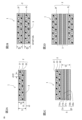
- FIG. 1A to 1D are schematic cross-sectional views showing the configurations of an insulating sheet according to a first embodiment and insulating sheets according to first to third modified examples, respectively.
- 2A to 2D are schematic cross-sectional views showing configurations of insulating sheets according to fourth to seventh modified examples of the first embodiment, respectively.
- 4 is a schematic cross-sectional view showing a process of insulating between a stator coil and a stator core using an insulating sheet according to the first embodiment.
- FIG. 10 is a flowchart showing a method for manufacturing an insulating sheet according to a second embodiment.
- 13 is a schematic cross-sectional view showing the configuration of a rotating electric machine manufactured using an insulation treatment method according to a third embodiment.
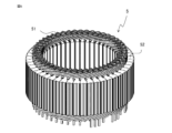
- FIG. 13 is a perspective view of a stator of a rotating electrical machine that is an object of insulation treatment in an insulation treatment method according to a third embodiment.
- FIG. 13 is a plan view of a stator of a rotating electrical machine that is an object of insulation treatment in the insulation treatment method according to the third embodiment.
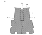
- FIG. 11 is a partial cross-sectional view showing an insulating state between a stator core and a stator coil in a stator of a rotating electric machine that has been subjected to an insulation method according to a third embodiment.
- 13 is a flowchart showing an insulation processing method according to a third embodiment.
- 13 is a flowchart showing a method for manufacturing a rotating electric machine according to a third embodiment.
- Fig. 1A to Fig. 3 are for explaining the insulating sheet according to the first embodiment
- Fig. 1A is a schematic cross-sectional view along the thickness direction for explaining the configuration of the insulating sheet according to the first example
- Figs. 1B to 1D are schematic cross-sectional views corresponding to Fig. 1A of the insulating sheet according to the first to third modified examples, respectively
- Figs. 2A to 2D are schematic cross-sectional views corresponding to Fig. 1A of the insulating sheet according to the fourth to seventh modified examples, which are examples in which a filler is added to the first example and the first to third modified examples, respectively.
- Fig. 3 is a schematic cross-sectional view showing a process of insulating between a stator coil and a stator core constituting a rotating electric machine using the above-mentioned insulating sheet.
- the insulating sheet 1 has an insulating resin layer 2 made of an uncured or semi-cured thermosetting resin composition formed on one or both sides of a substrate 3.
- the thermosetting resin composition has thermally expandable microcapsules 22 dispersed in a thermosetting resin portion 21, and is applied to the substrate 3 to form the insulating resin layer 2.
- the insulating sheet 1 is placed in the gap between the components to be insulated, and then heated and cured in a curing process to provide strong insulation between the components. Specifically, the insulating sheet 1 is placed in advance on one of the components (stator coil 51, stator core 52, etc.), and is then pressed and fixed to the other component (same as above). At this time, if the insulating sheet 1 does not have a surface adhesiveness as described below, it may be attached with double-sided tape or the like to prevent it from falling off.
- thermally expandable resin part 21C the thermally expandable resin part that has been hardened by the curing process described below is called “thermally expandable resin part 21C”
- thermally expandable microcapsules 22E the thermally expandable microcapsules after expansion are called “thermally expandable microcapsules 22E", distinguishing them by adding "C” or "E” to the end of the reference numeral.
- the composition of the insulating resin layer 2 is adjusted so that it is efficiently compressed to a specified thickness when pressurized at room temperature, and flows when heated during curing, penetrating into the fine spaces between the components, and then the varnish layer thickens due to foaming of the thermally expandable microcapsules 22. This eliminates air spaces and reliably fills the gaps between the components to be insulated, insulating and bonding them together.
- the heating temperature may be set not to a constant temperature, but to be increased stepwise to the flow temperature, foaming temperature, and hardening temperature.
- the flow temperature is set to a temperature below the foaming start temperature of the thermally expandable microcapsules 22, the foaming temperature is set to a temperature above the foaming start temperature of the thermally expandable microcapsules 22 and below the reaction start temperature of the latent hardener + 20°C, and the hardening temperature is set to a temperature above the reaction start temperature of the latent hardener.
- any one of insulating paper, thermoplastic insulating film, nonwoven fabric, and mesh cloth is used for the base material 3.
- an insulating resin layer 2 formed by applying a thermosetting resin composition is formed on one side of the base material 3
- an insulating resin layer 2 is formed on both sides of the base material 3.
- the base material 3 is not necessarily formed by a single base material sheet 31 (in the figures, the base material 3 is formed by a single sheet, so the reference number "31" for the base material sheet is omitted).
- a plurality of base material sheets 31a, 31b, and 31c may be laminated with adhesives 32a and 32b (collectively referred to as adhesive 32 as well).
- an insulating resin layer 2 may be formed on the base material sheet 31 at one end or both ends in the thickness direction of the base material 3.
- an insulating resin layer 2 is formed on the base sheet 31a at one end.
- a top insulating resin layer 2f and a bottom insulating resin layer 2r are formed on the base sheets 31a and 31c at both ends, respectively.
- the portion labeled adhesive 32 in FIG. 1C, FIG. 1D, FIG. 2C, and FIG. 2D may be composed of an insulating resin layer.
- the insulating resin layer is flexible and has a high adhesive strength with the base sheet 31, so the base sheets 31 can be bonded together by heating and pressing.
- each of sheets 32a, 32b, and 32c may be any of the insulating paper, insulating film, nonwoven fabric, and mesh cloth described above, and may all be the same or different.
- the number of base sheets 31 included in insulating sheet 1 is not particularly limited. However, since the total thickness of insulating sheet 1 increases as the number of sheets increases, it is preferable to use about three sheets.
- the insulating paper, insulating film, nonwoven fabric, and mesh cloth that form the base sheet 31 are made of insulating materials, and may be selected from known materials appropriately to impart the desired characteristics such as flexibility, or a combination of multiple materials may be used.
- the material of the base sheet 31 may be, for example, an insulating resin material made of engineering plastic or super engineering plastic, an inorganic insulating material made of silica, alumina, or glass, or a fibrous insulating resin material or a material containing a fibrous inorganic insulating material.
- Insulating resin materials are flexible and can be advantageously molded, while inorganic insulating materials have high thermal conductivity and can increase the heat dissipation from the heated stator coil 51 to the stator core 52.
- Nonwoven fabric may be any of general-purpose nonwoven fabrics, microfiber nonwoven fabrics, and nanofiber nonwoven fabrics.
- the base material 3 when the base material 3 is formed from a laminated sheet of multiple base material sheets 31, it is desirable to form it by laminating, for example, either one or both of insulating paper and insulating film. By forming the base material 3 by lamination, the thickness can be freely selected. In addition, by laminating a combination of insulating paper and insulating film, a base material 3 can be formed that makes use of the characteristics of each. When the base material 3 is formed from multiple insulating papers, the base material 3 is a composite insulating paper. When the base material 3 is formed from multiple insulating films, the base material 3 is a composite insulating film.
- the strength of the base material 3 can be increased by laminating it through a layer of insulating resin or adhesive 32.
- an inorganic filler is added to the adhesive 32, the thermal conductivity of the adhesive 32 can be increased, so that the heat dissipation effect of the base material 3 can be improved.
- the adhesive 32 used is, for example, a general-purpose acrylic or epoxy adhesive, or a highly heat-conductive adhesive containing filler 23.
- a base material 3 laminated with highly heat-resistant aramid paper, polyethersulfone, polyphenylene sulfide, polyetheretherketone, polyethylene naphthalate, polyimide, etc. is suitable.
- through holes may be provided in the base material 3 and filled with insulating resin to increase the amount of heat dissipated from the object of insulation treatment, for example, the stator coil 51 to the stator core 52.
- thermosetting resin composition constituting the insulating resin layer 2 and the insulating resin layer for laminating the above-mentioned multiple base sheets 31.
- the thermosetting resin composition is a thermosetting resin portion 21 in which thermally expandable microcapsules 22 are dispersed, and is applied to the above-mentioned base material 3 to form the insulating resin layer 2.
- thermosetting resin part 21 is composed of thermosetting resin A (first curing resin) which is solid at 25°C, thermosetting resin B (second thermosetting resin) which is liquid at 25°C, and a latent curing agent which is inactive at 60°C or less.
- thermosetting resin A first curing resin
- thermosetting resin B second thermosetting resin
- latent curing agent which is inactive at 60°C or less.
- the thermally expandable microcapsules 22 have a foaming start temperature of 60°C or more.
- the substrate 3 is flexible but incompressible with respect to thickness t3.
- the actual dimension of the gap to be filled by the insulating resin layer 2 is the dimension of gap G5 minus the thickness t3 of the substrate 3 (referred to as actual gap Gp).
- the thermally expandable microcapsules 22 are particles whose maximum particle size is smaller than the actual gap Gp and whose average particle size ⁇ 22 is smaller than 0.5 times the actual gap Gp. Furthermore, from the viewpoint of improving the smoothness of the insulating resin layer 2, it is preferable that the maximum particle size is smaller than the film thickness of the insulating resin layer (2 in the case of one side, 2f and 2r in the case of both sides) formed on each side of the substrate 3.
- the film thickness t2 of the insulating resin layer 2 is adjusted to a value between 1.1 and 2.0 times the actual gap Gp, as described below, and by back-calculation, the actual gap Gp is in the range between 0.5 and 0.91 times the film thickness t2. Therefore, the maximum particle size of the thermally expandable microcapsules 22 is smaller than 0.5 and 0.91 times the film thickness t2, and the average particle size ⁇ 22 is smaller than the range between 0.25 and 0.45 (strictly speaking, (1/1.1)/2) times the film thickness t2.
- thermosetting resin composition contains 10 parts by mass or more and 90 parts by mass or less of the first thermosetting resin for a total of 100 parts by mass of the first thermosetting resin and the second thermosetting resin, and optionally contains inorganic or resin-based filler 23, curing accelerator, thermoplastic resin, film-forming agent, tackifier, adhesion agent, etc.
- thermosetting resin room temperature refers to approximately 25°C.
- the insulating resin layer 2 formed on the substrate 3 by the thermosetting resin composition composed of the thermosetting resin part 21 made by combining the above-mentioned raw materials and the thermally expandable microcapsules 22 has the flexibility to be compressed to a predetermined thickness when pressurized at room temperature. Furthermore, it has the property that after flowing due to heating during curing and penetrating into the fine details between the components, the thickness of the layer called the varnish layer increases due to foaming of the thermally expandable microcapsules 22. Therefore, the insulating resin layer 2 constituting the insulating sheet 1 in embodiment 1 is suitable for reliably filling the gaps between the components to be insulated, and insulating and bonding them together.
- Thermosetting resins include known resins such as epoxy resins, phenolic resins, unsaturated polyester resins, polyurethane resins, diallyl phthalate resins, and silicone resins.
- epoxy resins such as epoxy resins, phenolic resins, and unsaturated polyester resins such as vinyl ester resins, which are commonly used as insulating varnishes.
- thermosetting resins include bisphenol A type epoxy resins, bisphenol F type epoxy resins, bisphenol AD type epoxy resins, brominated bisphenol A type epoxy resins, brominated bisphenol F type epoxy resins, brominated bisphenol AD type epoxy resins, alicyclic epoxy resins, brominated alicyclic epoxy resins, phenol novolac type epoxy resins, cresol novolac type epoxy resins, brominated phenol novolac type epoxy resins, brominated cresol novolac type epoxy resins, hydrogenated bisphenol A type epoxy resins, triglycidyl isocyanate, hydantoin type epoxy resins, heterocyclic epoxy resins, biphenyl skeleton-containing aralkyl type epoxy resins, dicyclopentadiene type epoxy resins, novolac type phenolic resins, resol type phenolic resins, epoxy (meth)acrylate resins (vinyl ester resins), urethane (meth)acrylate resins, polyether (
- the first thermosetting resin is solid at room temperature, and has a melting point or a softening temperature of glass transition point of 160°C or less, and more preferably 125°C or less. If the softening temperature exceeds 160°C, the polymerization reaction with the second thermosetting resin does not proceed easily when heated, and the heating temperature in the hardening process must be higher than 200°C, which is undesirable since it induces deterioration of the components to be insulated.
- the first thermosetting resin must be soluble in at least one of the liquid second thermosetting resin and the organic solvent for dilution (hereinafter referred to as the diluent). If it is not soluble, the resin components will not be evenly dissolved when the slurry is made, and a homogeneous insulating sheet cannot be formed.
- the first thermosetting resin is an epoxy resin
- an epoxy resin having an epoxy equivalent of 200 or more and a softening temperature in the range of 50°C or more and 160°C or less is more preferable.
- the first thermosetting resin is an unsaturated polyester resin such as a vinyl ester resin
- the softening temperature is 50°C or more and 160°C or less.
- thermosetting resin When the first thermosetting resin is an epoxy resin, an epoxy resin that is liquid at room temperature is suitable for the second thermosetting resin in order to increase the adhesive strength with the components to be insulated. Furthermore, in order to increase the dissolving power of the first thermosetting resin, bisphenol A type epoxy resin and bisphenol F type epoxy resin are more preferably used as the second thermosetting resin. Furthermore, when the first thermosetting resin is an unsaturated polyester resin, a low-viscosity, low-molecular-weight oligomer or monomer of unsaturated polyester resin is suitable for the second thermosetting resin in order to increase the dissolving power of the first thermosetting resin.
- thermosetting resin layer 2 by using two thermosetting resins (first thermosetting resin and second thermosetting resin) that are different in state at room temperature and adjusting the mass ratio, etc., it is possible to control the surface adhesion (tackiness), mechanical strength (toughness), adhesion, fluidity when heated, etc., of the insulating resin layer 2 at room temperature.
- the first thermosetting resin is preferably 10 parts by mass or more and 90 parts by mass or less, and more preferably 15 parts by mass or more and 85 parts by mass or less.
- the first thermosetting resin is less than 10 parts by mass, there will be too much liquid resin, and a stable insulating resin layer 2 will not be obtained after drying, and it will not be possible to peel it off from the release substrate.
- it exceeds 90 parts by mass there will be too much solid resin, and the toughness (tenacity of the material) of the insulating resin layer 2 will be reduced. As a result, cracks and chips are likely to occur during drying or when peeling off from the release substrate, making it difficult to work with.
- the first thermosetting resin is preferably in the range of 15 parts by mass or more and 85 parts by mass or less. Also, in order to ensure adhesion that allows easy attachment to the component to be insulated, the range is preferably 15 parts by mass or more and 50 parts by mass or less. On the other hand, if adhesion on the surface of the insulating resin layer 2 is not necessary (for example, if adhesion deteriorates workability), the range is preferably 50 parts by mass or more and 85 parts by mass or less in order to reduce surface adhesion, and the composition can be adjusted according to the application.
- the thermosetting resin portion 21 may also contain a curing agent that hardens the thermosetting resin.
- the curing agent is not particularly limited, and a known curing agent may be appropriately selected according to the type of thermosetting resin. Examples of the curing agent that may be used include amines, phenols, acid anhydrides, imidazoles, polymercaptan curing agents, polyamide resins, etc.
- hardeners include alicyclic acid anhydrides such as methyltetrahydrophthalic anhydride, methylhexahydrophthalic anhydride, and himic anhydride, aliphatic acid anhydrides such as dodecenylsuccinic anhydride, aromatic acid anhydrides such as phthalic anhydride and trimellitic anhydride, aromatic diamines such as dicyandiamide and 4,4'-diaminodiphenylsulfone, organic dihydrazides such as adipic acid dihydrazide, boron halide amine complexes such as boron trifluoride, boron trichloride, and boron tribromide, tris(dimethylamine)
- imidazoles such as 1-cyanoethyl-2-methylimidazole, 2-methylimidazole, 2-ethyl-4-methylimidazole, 2-phenylimidazole, and 1-cyanoethyl-2-methyl
- boron halide amine complexes listed above include boron trifluoride monoethylamine complex, boron trifluoride diethylamine complex, boron trifluoride isopropylamine complex, boron trifluoride chlorophenylamine complex, boron trifluoride triallylamine complex, boron trifluoride benzylamine complex, boron trifluoride aniline complex, boron trichloride monoethylamine complex, boron trichloride phenol complex, boron trichloride piperidine complex, boron trichloride dimethyl sulfide complex, boron trichloride N,N-dimethyloctylamine complex, boron trichloride N,N-dimethyldodecylamine complex, boron trichloride N,N-diethyldioctylamine complex, etc.
- These curing agents may be
- the amount of hardener to be used may be adjusted as appropriate depending on the type of thermosetting resin and hardener used, and is usually preferably 0.1 parts by mass or more and 200 parts by mass or less per 100 parts by mass of thermosetting resin.
- latent curing agent that is reactively inactive at 60°C or less is preferable from the viewpoints of storage stability, curing ability, and cured resin properties of the insulating resin layer 2.
- latent curing agents include boron halide amine complexes such as boron trifluoride-amine complexes, dicyandiamide, organic acid hydrazides, and aromatic diamines such as 4,4'-diaminodiphenylsulfone. These latent curing agents may be used alone or in combination of two or more types.
- the amount of latent curing agent blended is such that the equivalent ratio of the thermosetting resin to the epoxy resin is 0.3 or more and 2.0 or less, and from the viewpoint of stability of the cured product properties, it is more preferable that it is 0.5 or more and 1.5 or less.
- the organic peroxides listed above are used as a reaction initiator to start the polymerization reaction.
- the organic peroxide there are no particular limitations on the organic peroxide, so long as it has a 10-hour half-life temperature of 40°C or higher, and any organic peroxide known in the art can be used.
- Specific examples of organic peroxides include ketone peroxides, peroxyketals, hydroperoxides, dialkyl peroxides, diacyl peroxides, peroxy esters, and peroxydicarbonates. These organic peroxides may be used alone or in a mixture of two or more types.
- the usable life of the insulating resin layer 2 (i.e., the usable life of the insulating sheet) can be improved.
- the 10-hour half-life temperature of the organic peroxide is 80°C or higher.
- the 10-hour half-life temperature of the organic peroxide is equal to or lower than the set temperature of the curing furnace when curing the insulating resin layer 2.
- organic peroxides having such a 10-hour half-life temperature include 1,1-di(t-butylperoxy)cyclohexane, 1,1-di(t-hexylperoxy)cyclohexane, 1,1-di(t-hexylperoxy)-3,3,5-trimethylcyclohexane, 1,1-di(t-butylperoxy)-2-methylcyclohexane, 2,2-di(4,4-di-(butylperoxy)cyclohexyl)propane, n-butyl 4,4-di-(t-butylperoxy)valerate, 2,2-di-(t-butylperoxy)butane, t-hexylperoxyisopropyl monocarbonate, t-butylperoxymaleic acid, t-butylperoxy-3,5,5-trimethylhexanoic acid, t-butylperoxylauric acid, t-
- the amount of organic peroxide is not particularly limited, but is usually 0.1 parts by mass or more and 10 parts by mass or less, and more preferably 0.5 parts by mass or more and 5 parts by mass or less, per 100 parts by mass of the polyester resin, which is a thermosetting resin. If the amount of organic peroxide is less than 0.1 parts by mass, the crosslink density will be low and curing may be insufficient. On the other hand, if the amount of organic peroxide is more than 10 parts by mass, the usable time of the insulating resin layer 2 tends to be significantly shortened.
- the thermosetting resin portion 21 may contain a curing accelerator as necessary.
- the curing accelerator is not particularly limited, and a known one may be appropriately selected according to the type of thermosetting resin. Specific examples of curing accelerators include tertiary amines, imidazoles, and amine adducts. From the viewpoints of the storage stability, curing property, and cured resin properties of the insulating resin layer 2, curing accelerators that are inactive at 60°C or less are more preferable.
- the amount of the curing accelerator is usually 0.01 parts by mass or more and 10 parts by mass or less, and more preferably 0.02 parts by mass or more and 5.0 parts by mass or less, per 100 parts by mass of the total thermosetting resin. If the amount of the curing accelerator is less than 0.01 parts by mass, the effect of accelerating the curing reaction is poor, and if it exceeds 10 parts by mass, the usable time tends to be shortened.
- thermosetting resin portion 21 may contain a film-forming agent as necessary to improve film-forming properties such as film thickness uniformity and surface smoothness.
- a thermoplastic resin having a weight average molecular weight of 10,000 or more and 100,000 or less is used as the film-forming agent.
- the thermoplastic resin is 1 part by mass or more and 50 parts by mass or less per 100 parts by mass of the first thermosetting resin and the second thermosetting resin.
- the thermoplastic resin is not particularly limited, and a known thermoplastic resin can be appropriately selected according to the type of thermosetting resin. Specific examples of thermoplastic resins include phenoxy resin, saturated polyester resin, etc. These film-forming agents may be used alone or in combination of two or more types.
- the weight average molecular weight of the thermoplastic resin is less than 10,000, the film-forming properties are not improved, and if it exceeds 100,000, the solubility and dispersibility in the liquid second thermosetting resin is poor, making it impossible to prepare a slurry.
- the amount of the film-forming agent is usually 1 part by mass or more and 50 parts by mass or less, and more preferably 5 parts by mass or more and 45 parts by mass or less, per 100 parts by mass of the thermosetting resin in total, from the viewpoints of curing acceleration and cured resin properties.
- the film-forming agent is less than 1 part by mass, the effect of improving the film-forming properties is poor, and if it exceeds 50 parts by mass, the solubility and dispersibility in the liquid second thermosetting resin is poor, making it impossible to prepare a slurry.
- the thermosetting resin portion 21 may contain a tackifier as necessary to improve the surface adhesion of the insulating resin layer 2.
- a tackifier there are no particular limitations on the tackifier, so long as it has a weight-average molecular weight of 10,000 or more and 200,000 or less, and any known tackifier may be appropriately selected according to the type of thermosetting resin.
- Specific examples of tackifiers include terpene resins, rosin resins, natural rubber, styrene elastomers, polyvinyl acetal resins, polyvinyl formal resins, and polyvinyl butyral resins. These tackifiers may be used alone or in combination of two or more types.
- the amount of tackifier to be mixed is usually 1 part by mass or more and 20 parts by mass or less, and more preferably 2 parts by mass or more and 10 parts by mass or less, per 100 parts by mass of thermosetting resin in total.
- the amount of tackifier is less than 1 part by mass, the effect of improving surface adhesion is poor, and if it exceeds 20 parts by mass, it is poorly soluble and dispersible in the liquid second thermosetting resin, making it impossible to prepare a slurry.
- the thermosetting resin portion 21 may contain an adhesion promoter in order to improve the adhesive strength at the interface between the thermosetting resin and the inorganic filler (filler 23) or at the interface between the insulating resin layer 2 and the member to be insulated.
- an adhesion promoter there are no particular limitations on the adhesion promoter, and any known adhesion promoter may be appropriately selected according to the type of thermosetting resin or inorganic filler.
- adhesion promoters include silane coupling agents such as ⁇ -glycidoxypropyltrimethoxysilane, N- ⁇ (aminoethyl) ⁇ -aminopropyltriethoxysilane, N-phenyl- ⁇ -aminopropyltrimethoxysilane, and ⁇ -mercaptopropyltrimethoxysilane. These adhesion promoters may be used alone or in combination of two or more.
- the amount of adhesion promoter may be appropriately set according to the type of thermosetting resin or adhesion promoter, and is usually preferably 0.01 to 5 parts by mass per 100 parts by mass of thermosetting resin.
- the insulating resin layer 2 is made up of only the thermosetting resin portion 21, if the surface of the component to be insulated is highly uneven, or if the insulating resin layer 2, which is a varnish layer, has high thermal fluidity, the gaps between the components to be insulated may not be filled, and partial voids may occur.
- the thermosetting resin composition contains thermally expandable microcapsules 22 dispersed within it, the thermally expandable microcapsules 22 expand when heated, thickening the varnish layer and eliminating the voids, thereby reliably filling the gaps between the components.
- the varnish layer is pressed against the material, so that when heated, the varnish flows and permeates into the stator coil 51 by capillary action, thereby bonding the stator coils 51 together.
- the thermally expandable microcapsules 22 have preferred ranges for particle size, foaming start temperature, and size after expansion, as described below, but there are no particular limitations on the material.
- they may have a structure in which a thermal expansion agent such as a low-boiling point hydrocarbon is encapsulated in a thermoplastic polymer shell made of a thermoplastic resin with gas barrier properties, such as vinylidene chloride resin or acrylic resin. This allows the thermoplastic resin of the shell to soften when heated, increasing the volume of the thermal expansion agent and causing the capsule to expand.
- thermally expandable microcapsules 22 may be coated with an inactive inorganic powder such as calcium carbonate, talc, or titanium oxide.
- an inactive inorganic powder such as calcium carbonate, talc, or titanium oxide.
- microparticles that expand when heated may be used, such as microspheres that are commercially available.
- These thermally expandable microcapsules 22 may be used alone or in a mixture of two or more types.
- the insulating sheet 1 is placed by pasting or inserting in the gap between the components to be insulated, such as the stator coil 51 and the stator core 52, and is used as interphase insulation.
- the maximum particle size of the thermally expandable microcapsules 22 is smaller than the film thickness of the insulating resin layer (2 in the case of one side, 2f and 2r in the case of both sides) formed on each side of the substrate 3, and is smaller than the range of 0.5 to 0.91 times the total thickness (film thickness t2).
- the average particle size ⁇ 22 is smaller than 0.5 times the film thickness of the insulating resin layer (2 in the case of one side, 2f and 2r in the case of both sides) formed on each side of the substrate 3, and is smaller than the range of 0.25 to 0.45 times the total thickness (film thickness t2).
- thermally expandable microcapsules 22 are selected that have a maximum particle size of 10 ⁇ m or less and an average particle size ⁇ 22 of 5 ⁇ m or less. Also, from the viewpoint of improving the surface smoothness of the insulating resin layer 2, it is preferable to select thermally expandable microcapsules 22 whose maximum particle size is smaller than the film thickness of the insulating resin layer 2 that they form.
- the insulating resin layer 2 Since the insulating resin layer 2 is semi-cured or uncured, it flows when heated and functions as a varnish that penetrates into recesses on the surface of the component to be insulated and into the gaps between the components to be insulated. In order to allow efficient penetration and to minimize hardening during flow, a latent hardener that is inactive at temperatures below 60°C is used. On the other hand, if the thermally expandable microcapsules 22 foam when flowing as a varnish, this will hinder penetration into recesses or gaps, so the foaming start temperature of the thermally expandable microcapsules 22 is set to 60°C or higher.
- the foaming start temperature is equal to or lower than the reaction start temperature of the latent hardener plus 20°C. If the reaction start temperature of the latent hardener is lowered by a hardening accelerator, it is preferable to set the temperature equal to or lower than the reaction start temperature plus 20°C.
- the insulating resin layer 2 In order for the insulating resin layer 2 to bond between the members to be insulated, eliminate remaining voids, and reliably fill the gaps between the members, it is necessary to link the flow, foaming, and hardening by heating. In other words, it is desirable to determine the heating conditions such that the thermally expandable microcapsules 22 do not foam during flow, foam after flow is completed, and hardening begins after foaming, by raising the temperature or increasing it in stages.
- the amount of thermally expandable microcapsules 22 to be mixed is not particularly limited, but if the expansion ratio is too high, it will cause a large decrease in strength and heat resistance of the cured insulating resin layer 2C (called “insulating resin layer 2C" when distinguishing it from the insulating resin layer 2 before curing). Therefore, it is desirable to adjust the amount so that it can reliably fill the irregularities on the surface of the component to be insulated and the gaps between the components, but since the expansion ratio of thermally expandable microcapsules 22 varies depending on the type and heating temperature, it is difficult to uniformly prescribe the amount to be mixed.
- the amount is usually 1 part by mass or more and 100 parts by mass or less per 100 parts by mass of thermosetting resin, and from the viewpoint of ensuring the thermal fluidity of the varnish, it is more preferably 90 parts by mass or less. If it is less than 1 part by mass, the increase in thickness of the insulating resin layer 2 due to the foaming of the thermally expandable microcapsules 22 will be insufficient, and the gaps between the components will not be filled reliably, and if it exceeds 100 parts by mass, the thermal fluidity of the varnish will be poor and the stator coil 51 will not be able to be fixed.
- inorganic blowing agents such as ammonium carbonate, ammonium borohydride, ammonium hydrogen carbonate, ammonium nitrite, and azides
- organic blowing agents such as azo compounds such as azobisisobutyronitrile, fluorinated alkanes such as trichloromonofluoromethane, semicarbazide compounds such as p-toluenesulfonylsemicarbazide, hydrazine compounds such as paratoluenesulfonylhydrazide, triazole compounds such as 5-morpholyl-1,2,3,4-thiatriazole, and N-nitroso compounds such as N,N'-dinitrosoterephthalamide may be used in combination as necessary.
- the thermosetting resin composition may contain a filler 23 from the viewpoint of improving thermal conductivity and mechanical strength, thickening the insulating resin layer 2, etc.
- the filler 23 is not particularly limited, and any known filler may be appropriately selected according to the purpose.
- the filler 23 may be surface-treated with a silane coupling agent, a titanate coupling agent, etc., or may not be surface-treated.
- inorganic fillers among the fillers 23 include crystalline silica, fused silica, alumina, talc, clay, calcium carbonate, calcium silicate, titanium dioxide, silicon nitride, aluminum hydroxide, aluminum nitride, boron nitride, glass, barium sulfate, magnesia, beryllium oxide, mica, magnesium oxide, etc.
- the shape of the filler 23 is preferably crushed or spherical, but may also be subspherical, flaky, fibrous, milled fiber, whisker, etc. These fillers 23 may be used alone or in a mixture of two or more types.
- thermoplastic resins include butyral resin, polyvinyl acetal resin, polyamide resin, aromatic polyester resin, phenoxy resin, MBS resin (methyl methacrylate-butadiene-styrene copolymer), ABS resin (acrylonitrile-butadiene-styrene copolymer), and acrylic resin, which can be modified with silicone oil, silicone resin, silicone rubber, fluororubber, etc.
- various plastic powders, various engineering plastic powders, etc. may be added.
- the amount of filler 23 to be mixed may be any amount that allows it to be mixed uniformly in the thermosetting resin composition, and is usually 70% by volume or less relative to the total amount of the thermosetting resin composition, and more preferably 65% by volume or less when considering the ease of mixing. If the amount of filler 23 to be mixed is greater than 70% by volume, it will not be possible to mix it uniformly with the resin composition, and the characteristics of the insulating resin layer 2 will tend not to be reproducible. Furthermore, if the insulating sheet 1 is to be folded for use, it is necessary to increase its flexibility, so 50% by volume or less is more preferable. Furthermore, if there is no need to increase the thermal conductivity of the insulating sheet 1 or form a thick varnish layer, it is possible not to mix filler 23 into the thermosetting resin composition.
- the insulating sheet 1 is used as interphase insulation by being attached to or inserted into the gap between the components to be insulated.
- the maximum particle size of the filler 23 is also smaller than the actual gap Gp, and that the average particle size is smaller than 0.5 times the actual gap Gp.
- the maximum particle size of the filler 23 is smaller than the range of 0.5 to 0.91 times the total thickness (film thickness t2), and that the average particle size is smaller than the range of 0.25 to 0.45 times the total thickness (film thickness t2).
- the actual dimension obtained by subtracting the thickness t3 of the base material 3 from the gap dimension G5 is 10 ⁇ m or more and 100 ⁇ m or less, including tolerance, a filler 23 with a maximum particle size of 10 ⁇ m or less and an average particle size of 5 ⁇ m or less is selected. Also, if it is necessary to improve the surface smoothness of the insulating resin layer 2, it is preferable to select a filler 23 with a maximum particle size smaller than the film thickness t2 of the insulating resin layer 2 that it forms.
- thermosetting resin portion 21 may be blended with anti-settling agents or dispersants that suppress the settling of solid powders such as the filler 23 in the resin, anti-foaming agents that prevent the generation of voids, anti-blocking agents or slippage improvers such as polymer beads that prevent blocking between the insulating resin layers 2, paint fixing agents, antioxidants, flame retardants, colorants, thickeners, viscosity reducers, surfactants, etc.
- the insulating resin layer 2 has high surface smoothness and flexibility.
- the in-plane distribution of the film thickness t2 of the insulating resin layer 2 is set to within ⁇ 30% of the average value.
- the insulating resin layer 2 is also flexible enough that it will not crack even when bent 180 degrees at 25°C. If drying progresses due to excessive heating, the diluent will volatilize and the resin will begin to harden, causing the flexibility to be lost. In this case, the resin will not be flexible enough to conform to the surface shape of the components, and cracks may occur when it is placed between components, or it may not adhere or bond to the components even after being heated and hardened.
- the thickness t2 of the insulating resin layer 2 is too thick, the internal stress will be high, and cracks may occur when bending at 180 degrees.
- the thickness t2 of the insulating resin layer 2 is preferably 1 ⁇ m or more and 500 ⁇ m or less, and more preferably 5 ⁇ m or more and 300 ⁇ m or less in order to completely fill the gaps between the components to be insulated. If the thickness t2 is less than 1 ⁇ m, it is difficult to form an insulating resin layer 2 without pinholes, and if the thickness t2 exceeds 500 ⁇ m, there is a high possibility that cracks will occur during the 180-degree bending test.
- the film thickness t2 of the insulating resin layer 2 is 1.1 times or more the dimension obtained by subtracting the thickness t3 of the substrate 3 from the gap dimension G5 between the members to be insulated, and is usually set to 1.1 times or more and 2.0 times or less, and more preferably 1.3 times or more and 1.7 times or less.
- the film thickness t2 of the insulating resin layer 2 is preferably 110 ⁇ m or more and 200 ⁇ m or less, and more preferably 130 ⁇ m or more and 170 ⁇ m or less.
- the film thickness t2 is less than 110 ⁇ m, the heated insulating resin layer 2 does not sufficiently fill the fine details of the gap, and when it exceeds 200 ⁇ m, gaps occur between the slots 52s when the stator 5 of the rotating electric machine 80 is molded, making it impossible to mold it into a circular shape, and other problems may occur that deteriorate the ease of assembly.
- the insulating resin layer 2 needs to be compressed by 10% or more in thickness (total thickness) at 25°C and a pressure of 25 MPa.
- the insulating resin layer 2 is compressed by 20% or more in total thickness at 25°C and a pressure of 25 MPa. Since the insulating resin layer 2 has a non-volatile content of 97 mass parts (%) or more, there is a volumetric shrinkage of 3% to 10% when it is completely cured.
- the base material 3 of the insulating sheet 1 is hardly compressed at a pressure of 25 MPa, so the thickness t2 of the insulating resin layer 2 needs to be 10% or more larger than the dimension obtained by subtracting the thickness t3 of the base material 3 from the gap dimension G5. If the thickness t2 of the insulating resin layer 2 is compressed by less than 10% at 25°C and a pressure of 25 MPa, even if the gaps are filled when the insulating sheet 1 is placed, small gaps may occur due to hardening shrinkage.
- the insulating sheet 1 is to be attached to a component before use, it is preferable that it has surface adhesion (tackiness) at 25°C.
- surface adhesion taciness
- attaching it to the component beforehand reduces workability, it is possible to eliminate surface adhesion while maintaining flexibility and film thickness compressibility by using the above-mentioned blending ratio and drying conditions.
- the sheet does not adhere even when pressed against the component to be insulated at 40°C with a pressure of 2 MPa. If it adheres under these conditions, the surface adhesion may increase depending on the working environment temperature (25-35°C), potentially reducing workability.
- the insulating resin layer 2 of the insulating sheet 1 must have the flexibility to be compressed at 25°C, and must flow when heated and penetrate into the fine details between components (such as the uneven shapes of the stator coil 51 and stator core 52). To obtain these characteristics, the dry state of the insulating resin layer 2 is important. Flexibility can be easily determined by whether or not cracks occur when bent at 180°C. As a method for more quantitatively determining these flexibility and fluidity characteristics, elastic modulus evaluation by viscoelasticity measurement disclosed in Patent Document 1 may be used.
- the flexibility and fluidity characteristics of the insulating resin layer 2 can also be evaluated using complex viscosity.
- the complex viscosity at 25°C must be 6.0 x 10² Pa ⁇ s or more and 1.0 x 10⁴ Pa ⁇ s or less. It must also decrease with increasing temperature, with the minimum value being 5.0 x 10² Pa ⁇ s or less in the range of 80°C or more and 150°C or less.
- the complex viscosity at 25°C is 1.0 x 10³ Pa ⁇ s or more and 5.0 x 10³ Pa ⁇ s or less.
- the minimum value of the complex viscosity at 80°C or more and 150°C or less is 1 Pa ⁇ s or more and 5.0 x 10² Pa ⁇ s or less, and more preferably is 1/10 or less of the value at 25°C.
- the complex viscosity at 180°C or more will saturate at 1.0 x 10⁴ Pa ⁇ s or more due to the effects of hardening.
- the insulating resin layer 2 After curing, the insulating resin layer 2 has thermally expandable microcapsules 22 that foam, forming voids inside. Since voids reduce the insulating properties and mechanical strength of the cured product, the void size is an average of 30 ⁇ m or less to maintain insulating properties, and an average of 20 ⁇ m or less is more preferable to obtain uniform insulating properties and stable mechanical strength. If the void size exceeds an average of 30 ⁇ m, the insulating properties will deteriorate after the varnish hardens, such as a decrease in the dielectric breakdown voltage or the occurrence of partial discharges, and the mechanical strength will decrease, deteriorating the vibration resistance of the product.
- the thermally expandable microcapsules 22 can obtain hollow microparticles by controlling the heating temperature and heating time to change the internal gas pressure and adjust the increase in volume (expansion). It is necessary to set the heating temperature and heating time so that the pore size of the hollow microparticles is an average of 30 ⁇ m or less, and the heating temperature (foaming temperature) is preferably 60°C or more and 200°C or less, but it is essential that it is no more than the reaction start temperature of the latent hardener plus 20°C.
- the curing accelerator lowers the reaction start temperature of the latent curing agent, it is preferable to set the temperature at or below the reaction start temperature plus 20°C. In order to suppress foaming variation, a temperature of 80°C or higher and 180°C or lower is more preferable. If the temperature is less than 60°C, the flow of the varnish is hindered, and if the temperature exceeds 200°C, the varnish hardens first, causing foaming to cease or making it impossible to control the pore size.
- heating time is a time that allows the pore size to be controlled to an average of 30 ⁇ m or less, and from the viewpoint of suppressing foaming variation, a temperature of 30 seconds or more and 1 hour or less is preferable.
- the increase in thickness of the insulating resin layer 2 after curing is not particularly limited as long as the pore size of the hollow particles of the thermally expandable microcapsules 22 is an average of 30 ⁇ m or less and the gaps between the components to be insulated are reliably filled, but it is preferable that the film thickness after curing increases by 10% or more compared to the initial film thickness. If the increase is less than 10%, the fine details of the gaps cannot be filled and an air layer will remain. In other words, it is desirable to set the expansion rate of the thermally expandable microcapsules 22 and the content rate in the insulating resin layer 2 so that the volume of the insulating resin layer 2 can be expected to increase by 10% or more due to the expansion of the thermally expandable microcapsules 22 during the curing process.
- the insulating sheet 1 After being placed in the gap between the components to be insulated, the insulating sheet 1 is heated and cured in a curing process.
- the heating temperature in the curing process varies depending on the type of curing agent and curing accelerator, but is set to a heating temperature and time that will not deteriorate the components to be insulated.
- the heating temperature is preferably 100°C or higher and 200°C or lower, and more preferably 130°C or higher and 190°C or lower.
- the heating time is preferably 1 minute or higher and 6 hours or lower, and more preferably 3 minutes or higher and 2 hours or lower.
- the heating temperature is less than 100°C or the heating time is less than 1 minute, curing will be insufficient, making it difficult to adhere and bond to the components.
- the heating temperature is less than 100°C or the heating time is less than 1 minute, curing will be insufficient, making it difficult to adhere and bond to the components.
- the insulating sheet 1 contains almost no solvent, it can be cured by induction heating or electric heating, etc., making it possible to simplify the curing process.
- the adhesive strength of the insulating sheet 1 to the components after curing is preferably 10 N/m or more, and in order to suppress variation in vibration resistance characteristics, 20 N/m or more is more preferable. If the adhesive strength is less than 10 N/m, sufficient vibration resistance cannot be obtained, and the long-term reliability of the equipment decreases.
- the insulating sheet 1 is constructed to have the above-mentioned characteristics, the insulating resin layer 2 is efficiently compressed to a specified thickness when pressurized at room temperature, and flows when heated during hardening, penetrating into the fine spaces between the components.
- the varnish layer is then thickened by foaming the thermally expandable microcapsules 22, eliminating the air layer and reliably filling the gaps between the components to be insulated, thereby insulating and bonding them together.
- Embodiment 2 In the above embodiment 1, the configuration and applications of the insulating sheet, and the characteristics suitable for the applications have been described. In the present embodiment 2, a method for manufacturing the insulating sheet will be described.
- Fig. 4 is a flow chart for explaining the method for manufacturing the insulating sheet according to the embodiment 2.
- the manufacturing process of the insulating sheet 1 includes a first step (step S110) of preparing a slurry of a thermosetting resin composition, and a second step (steps S210-S220) of applying the slurry prepared in the first step to a substrate 3 or the like and drying it.
- a diluent is added to the thermosetting resin composition to achieve a predetermined mixture viscosity, and the mixture is stirred and mixed with a stirrer until the thermally expandable microcapsules 22 and the filler 23 are uniformly dispersed without settling, to prepare a slurry (step S110).
- the slurry contains at least a first thermosetting resin that is solid at 25°C, a second thermosetting resin that is liquid at 25°C, a latent curing agent, thermally expandable microcapsules 22 that have a foaming start temperature of 60°C or higher, an inorganic filler that is the filler 23, and a diluent.
- the thermally expandable microcapsules 22 are selected so that their maximum particle size is smaller than the actual gap Gp and their average particle size ⁇ 22 is less than 0.5 times the actual gap Gp.
- the filler 23 is selected so that its maximum particle size is smaller than the actual gap Gp and its average particle size is less than 0.5 times the actual gap Gp.
- thermosetting resin is contained in an amount of 10 parts by mass or more and 90 parts by mass or less per 100 parts by mass of the thermosetting resin in total, and the thermally expandable microcapsules 22 are blended in an amount of 1 part by mass or more and 100 parts by mass or less per 100 parts by mass of the thermosetting resin in total.
- the diluent that dissolves the thermosetting resin volatilizes or evaporates after coating and disappears almost completely.
- any known diluent can be selected appropriately according to the type of thermosetting resin and inorganic filler used.
- Specific examples of diluents include toluene and methyl ethyl ketone. These solvents may be used alone or in combination of two or more types.
- the slurry is applied to the substrate 3 or release paper or release film that constitutes the insulating sheet 1 by a sheet coater to a predetermined thickness (step S210).
- the slurry is then dried in a drying oven at a temperature of 80°C or higher and 160°C or lower to volatilize the diluent and form the insulating resin layer 2 (step S220).
- the coating method is not particularly limited, and may be performed using a coating machine known in the technical field.
- a third step step S310 is performed in which the thermosetting resin composition dried in the second step is transferred to one or both sides of the substrate 3 by heating and pressing.
- a laminator processing device or other device known in the technical field may be used in the third step.
- the insulating film or insulating paper which is the substrate 3, may be impregnated with the slurry produced in the first step, and while lifting it up, the diluent is evaporated in a drying furnace at a temperature condition of 80°C or higher and 160°C or lower to form the insulating resin layer 2.
- the film thickness t2 of the insulating resin layer 2 is adjusted by the viscosity of the slurry.
- the non-volatile content after drying is 97 parts by mass or more, more preferably 99 parts by mass or more, per 100 parts by mass of the total mass of the insulating resin layer 2. If it is less than 97 parts by mass, the remaining diluent makes it difficult to release from the release paper, etc.
- the insulating resin layer 2 may be in an uncured state (A stage state) where only the diluent has been volatilized, or may be in a semi-cured state (B stage state) where heating is further performed to promote the curing reaction after the diluent has been volatilized.
- the insulating resin layers 2 will adhere (block) when in contact with each other, so the surface of the insulating resin layer 2 is covered with a release film or release paper (step S410). This completes the insulating sheet 1, which is used by peeling off the release film when in use.
- Embodiment 3 an insulation processing method for insulating electrical equipment using the insulating sheet described in embodiment 1, more specifically, a manufacturing method for a rotating electric machine for insulating the stator coil and stator core using an insulating sheet, will be described.
- Figures 5 to 10 are used to explain the insulation method and manufacturing method of a rotating electric machine according to the third embodiment, with Figure 5 being a schematic cross-sectional view along the rotating shaft showing the configuration of a rotating electric machine manufactured using the insulation method.
- Figure 6 is a perspective view of a stator to be insulated, used to explain the manufacturing method of a rotating electric machine using the insulation method
- Figure 7 is a plan view of the stator
- Figure 8 is a partial cross-sectional view showing the insulation state of the stator core and stator coil in the stator of a rotating electric machine that has been subjected to the insulation method.
- Figure 9 is a flowchart showing the insulation method
- Figure 10 is a flowchart showing the manufacturing method of a rotating electric machine.
- a rotating electric machine 80 such as an electric motor, generator, or compressor has a stator 5 including a stator coil 51 and an annular stator core 52.
- a predetermined number of slots 52s are provided in the circumferential direction between the teeth 52t of the stator core 52, and the stator coil 51 is housed in the slots 52s.
- the gap between the stator core 52 (strictly speaking, the inner wall of the slot 52s) and the stator coil 51 is insulated by the cured insulating sheet 1C (insulator).
- This insulating sheet 1 may have an insulating resin layer 2 arranged on one or both sides of the substrate 3. That is, in the case of the rotating electric machine 80, the gap between the members to be insulated is the gap between the stator core 52 and the stator coil 51, the gap between the substrate 3 and the stator coil 51, or the gap between the stator core 52 and the substrate 3.
- insulating tape may be attached to the stator coil 51.
- the insulating sheet 1C in which the thermosetting resin composition forming the insulating resin layer 2 is cured, is arranged between the inner wall of the slot 52s and the stator coil 51, and insulates and fixes the stator core 52 and the stator coil 51.
- an insulating resin layer 2 having surface adhesion at 25°C is selected. Also, if attaching the insulating sheet 1 in advance reduces workability when inserting the stator coil 51, an insulating sheet 1 that does not have surface adhesion at 25°C is selected.
- the insulating sheet 1 may have the insulating resin layer 2 formed on both sides of the base material 3, or may have the insulating resin layer 2 formed on one side of the base material 3. If the insulating resin layer 2 is on only one side, or if the insulating resin layer 2 does not have surface adhesion, the insulating sheet 1 may be attached to the stator core 52 using double-sided tape or the like. Furthermore, if the insulating resin layer 2 is on only one side, for example, the insulating sheet 1 is placed so that the insulating resin layer 2 faces the stator coil 51 in order to fix the stator coil 51 to the stator core 52, among the objects to be insulated.
- step S810 When assembling the stator 5 in the manufacturing process (insulation process: step S810), the insulating sheet 1 is inserted or pasted into the gap between the stator core 52 and the stator coil 51 (step S710). Then, the stator core 52 is formed into an annular shape, whereby the insulating sheet 1 is compressed and fixed (pressed) between the stator core 52 and the stator coil 51, which are the areas to be insulated (step S720).
- the thickness t2 of the insulating resin layer 2 is set to 1.1 to 2.0 times, and more preferably 1.3 to 1.7 times, the dimension obtained by subtracting the thickness t3 of the substrate 3 from the dimension of the gap (gap dimension G5) between the stator core 52 (inner wall of the slot 52s) and the stator coil 51. Therefore, it is reduced by the pressure when the stator core 52 is molded into an annular shape. In other words, it is compressed by 10% or more, and more preferably 20% or more, at a pressure of 25 MPa at 25°C. Therefore, the thickness of the insulating sheet 1 inside the slot 52s is thinner than the thickness t1 of the insulating sheet 1 outside the slot 52s.
- a curing process (step S730) is performed.
- the insulating resin layer 2 penetrates into the gap between the stator core 52 and the stator coil 51 and into the fine gaps in the stator coil 51 due to the heating during the curing process.
- the thermally expandable microcapsules 22 are then expanded by heating, which increases the thickness of the insulating resin layer 2, eliminating the voids and reliably filling the gaps between the members.
- the thickness of the insulating resin layer 2 increases at the points where the insulating sheet 1 is folded, the gaps can be easily filled even if there is variation in the gap dimensions between the corners of the stator core 52 and the stator coil 51.
- the gaps at the corners of the stator core 52 and the stator coil 51 that existed before curing are filled by the insulating sheet 1C after the curing process.
- the adhesive strength of the cured insulating resin layer 2C to the stator core 52 and the stator coil 51 is 20 N/m or more.
- the stator 5, which has been insulated and assembled in this manner, is attached to, for example, the inner circumferential surface of the housing 7 (step S820). Then, the rotor 6 (FIG. 5) is rotatably attached to the housing 7 via a bearing (not shown) so that the outer circumferential surface faces the inner circumferential surface of the stator 5 via a magnetic gap (step S830). This completes the rotating electric machine 80 as shown in FIG. 5.
- the rotating electric machine 80 insulated using the insulating sheet 1 has high insulation performance of the stator coil 51 and is less susceptible to insulation deterioration.
- heat generated from the windings of the stator coil 51 can be efficiently dissipated to the stator core 52.
- the stator coil 51 can be reliably fixed, so mechanical strength is maintained and NVH characteristics are improved.
- the insulating sheet 1 contains almost no solvent, it can be cured not only by a general-purpose heating furnace but also by induction heating and current heating. Furthermore, since there is little energy loss during the curing process, the curing time is short and the manufacturing process of the rotating electric machine 80 is simplified. Therefore, the rotating electric machine 80 insulated using the insulating sheet 1 has improved insulation reliability, heat dissipation, and vibration resistance, and is compact and has high output.
- thermosetting resin composition A slurry was prepared by adding a diluent to these thermosetting resin compositions, and the slurry was applied to a substrate, and the diluent was evaporated and dried to prepare an insulating resin layer 2.
- a thermosetting resin composition A slurry was prepared by adding a diluent to these thermosetting resin compositions, and the slurry was applied to a substrate, and the diluent was evaporated and dried to prepare an insulating resin layer 2.
- the type of material in the thermosetting resin composition is indicated by "x"
- the first thermosetting resin is indicated by "1”
- the second thermosetting resin is indicated by "2”
- thermally expandable microcapsules are indicated by "6".
- composition within the type is indicated by "y".
- reference numerals are omitted, for example, "insulating resin layer”.
- thermosetting resin First thermosetting resin> (1-1) Bisphenol A type epoxy resin (epoxy equivalent: 1800, softening point: 120°C) (1-2) Bisphenol A vinyl ester resin (weight average molecular weight 2800, softening point 85°C)
- thermosetting resin second thermosetting resin>
- Bisphenol A type epoxy resin epoxy equivalent: 195
- Neopentyl glycol dimethacrylate weight average molecular weight 240
- ⁇ 6 Thermally Expandable Microcapsules> (6-1) Maximum particle size 13 ⁇ m, average particle size 10 ⁇ m, foaming start temperature 63°C (6-2) Maximum particle size 35 ⁇ m, average particle size 22 ⁇ m, foaming start temperature 125 °C (6-3) Maximum particle size 100 ⁇ m, average particle size 53 ⁇ m, foaming start temperature 178°C (6-4) Maximum particle size 40 ⁇ m, average particle size 28 ⁇ m, foaming start temperature 125°C (6-5) Maximum particle size 55 ⁇ m, average particle size 40 ⁇ m, foaming start temperature 185°C (6-6) Maximum particle size 100 ⁇ m, average particle size 50 ⁇ m, foaming start temperature 45°C (6-7) Maximum particle size 125 ⁇ m, average particle size 60 ⁇ m, foaming start temperature 120°C
- Inorganic filler> 7-1) Fused silica (maximum particle size 8 ⁇ m, average particle size 3 ⁇ m) (7-2) Alumina (maximum particle size 20 ⁇ m, average particle size 8 ⁇ m) (7-3) Crystalline silica (maximum particle size 130 ⁇ m, average particle size 65 ⁇ m)
- Substrate> Aramid paper (thickness 0.2 mm) (8-2) Polyethylene terephthalate (thickness 0.12 mm) (8-3) Composite insulating film: polyphenylene sulfide/polyethylene terephthalate/polyphenylene sulfide (thickness 0.18 mm, with interlayer adhesive) (8-4) Mesh cloth: Alumina (thickness: 0.24 mm, mesh size: 80 ⁇ m, Opening rate: 50%)
- the insulating resin layers 2 shown in Examples 1 to 6 are made according to the raw materials and their combinations described in the first embodiment.
- the insulating resin layers in Comparative Examples 1 to 7 do not follow the raw materials and their combinations described in the first embodiment, and are not compatible with the insulating sheet 1 of the present application.
- the insulating resin layers shown in Examples 1 to 6 and Comparative Examples 1 to 7 were evaluated for surface smoothness, flexibility, compressibility, adhesion, releasability, gelation time, storage shear modulus, loss modulus, loss tangent, and complex viscosity.
- the cured insulating resin layers were also evaluated for adhesive strength, dielectric strength, film thickness increase rate, and pore size of the thermally expandable microcapsules.
- a stator was produced, and the gap state between the stator coil and the stator core and the coil adhesion state were observed.
- the compressibility of the insulating resin layer was calculated from the reduction in the thickness of the insulating sheet when the insulating sheet was placed on a rolled steel plate and a pressure of 25 MPa was applied at 25°C.
- the evaluation of the compressibility was determined by whether the compressibility was 10% or more (good: 10% or more, bad: less than 10%).
- Adhesion was evaluated by placing the insulating sheet on a rolled steel plate and pressing it with a pressure of 2 MPa at 40°C to see whether it adhered or not, immediately after production and after storing it at 40°C for 30 days. Note that it is not possible to say which is better, as adhesion is sometimes preferable and sometimes not, depending on the application of the insulating sheet. However, it is not desirable for adhesion to change between immediately after production and after 30 days, so this was evaluated.
- the pinhole test was conducted in accordance with JIS C3003, in which a test piece of the specified length (approximately 5 m) was immersed in saline solution, and the liquid was used as the positive electrode and the test piece as the negative electrode, and a direct current voltage of 12 V was applied for 1 minute to check the number of pinholes that occurred.
- the test pieces that had been cured at 150°C for 1 hour after application were also observed under an optical microscope to see if there were any cracks or pinholes on the coating surface.
- the gel time was measured by taking a sample of the thermosetting resin composition of the insulating sheet and measuring the gel time at 150°C using the hot plate method.
- the softening point was measured by taking a sheet made of the thermosetting resin composition and measuring it in accordance with JIS C2161 "Test method for powder coatings for electrical insulation”.
- the storage shear modulus, loss modulus, loss tangent, complex viscosity, and minimum complex viscosity were measured by dynamic viscoelasticity evaluation using an insulating resin layer with a thickness of 100 ⁇ m to 300 ⁇ m and heating it from room temperature at a heating rate of 5°C/min using a parallel plate jig.
- test pieces used to measure the cured properties of the insulating resin layer were prepared by heating the test pieces in a heating furnace from room temperature to 150°C in 10 minutes, and curing them at 150°C for 1 hour, in order to sequentially proceed through the flow, foaming, and curing of the varnish.
- Adhesive strength was evaluated by preparing adhesive test specimens and using a tensile tester. Adhesive strength was evaluated by preparing adhesive test specimens and using a tensile tester. Adhesive test specimens were prepared by pressing an insulating sheet against an electromagnetic steel plate with a treated surface that had been degreased with acetone, and then curing the sheet. The tensile test was performed at 25°C with a peel angle of 180° and a pulling speed of 10 mm/min, and was evaluated according to the following criteria ( ⁇ : adhesive strength of 10 N/m or more, ⁇ : adhesive strength of less than 10 N/m).
- the dielectric strength was measured by attaching an insulating sheet to one side of a steel plate, heating it from room temperature to 150°C in 10 minutes, and curing it at 150°C for 1 hour.
- the dielectric breakdown voltage was measured by applying a constant voltage of 0.5 kV/sec to the test specimen in oil using a dielectric breakdown tester, and the dielectric breakdown voltage was evaluated according to the following criteria ( ⁇ : dielectric breakdown voltage 8 kV or more, ⁇ : dielectric breakdown voltage 8 kV or less).
- the film thickness increase rate was calculated by dividing the film thickness after curing by the film thickness before curing to confirm whether or not there was an increase in thickness after curing.
- the pore size of the thermally expandable microcapsules after curing was measured by cross-sectional observation and judged ( ⁇ : average particle size 30 ⁇ m or less, ⁇ : over 30 ⁇ m).
- a stator was produced by changing the cross-sectional shape of the wire of the stator coil 51 in FIG. 8 from a rectangular shape to a round wire with a diameter of 1.5 mm so that the gap between the stator coil and the stator core would be larger.
- An insulating sheet with an insulating resin layer formed on one or both sides with a total thickness of 120 ⁇ m was inserted and pressed into the gap (gap dimension G5) of 100 ⁇ m between the stator coil and the stator core, and then the temperature was raised from room temperature to 150°C in 10 minutes and cured at 150°C for 1 hour.
- the cross section was observed to confirm whether there was an air layer between the stator core and the stator coil ( ⁇ : no air layer, ⁇ : air layer). Furthermore, the stator coil was removed to confirm the adhesion state between the stator coils ( ⁇ : completely adhered, ⁇ : not adhered).
- Table 3 shows the evaluation results for the insulating sheets shown in Examples 1 to 6, and Table 4 shows the evaluation results for the insulating sheets shown in Comparative Examples 1 to 7.
- the insulating sheets shown in Examples 1 to 5 have excellent flexibility and releasability immediately after production and after 30 days, and have a compression rate of 20% or more. They do not cause crazing on enameled wire.
- the storage shear modulus at 25°C is in the range of 1.0 x 10 Pa to 5.0 x 10 4 Pa, with the minimum value being in the range of 10 Pa to 2.0 x 10 3 Pa at 80°C to 150°C.
- the loss modulus at 25°C is in the range of 1.0 x 10 3 Pa to 5.0 x 10 4 Pa, with the minimum value being in the range of 10 Pa to 2.0 x 10 3 Pa at 80°C to 150°C.
- the maximum value of the loss tangent is within the range of 1.0 to 3.5 at temperatures between 80°C and 150°C.
- the complex viscosity at 25°C is within the range of 6.0 x 10² Pa ⁇ s to 1.0 x 10⁴ Pa ⁇ s, and its minimum value is within the range of 80°C to 150°C and 500 Pa ⁇ s.
- the insulating resin layers 2 of Examples 1 to 6 all have an adhesive strength of 20 MPa or more at 25°C, and can firmly bond and fix the components to be insulated. Furthermore, they have a high dielectric strength after curing, and excellent insulation reliability. Furthermore, there is no change in flexibility and compressibility after 30 days of storage at 40°C, which indicates that the reaction progresses slowly at room temperature and the usable life is long.
- the thermally expandable microcapsules 22 foam after curing, with a pore size of 30 ⁇ m or less, and the varnish film thickness also increases. Furthermore, in verification using a stator, there was no gap between the stator coil and the stator core, and the stator coil was completely fixed, and high adhesive strength and dielectric strength were obtained in all cases.
- Comparative Example 1 although similar to the formulation of Example 1, does not contain thermally expandable microcapsules, so the varnish layer does not thicken after hardening, and the gap between the stator coil and the stator core is not filled, leaving an air layer.
- Comparative Example 2 has a similar composition to Example 2, but contains 105 parts by mass of thermally expandable microcapsules (6-1) per 100 parts by mass of thermosetting resin. As a result, it is not possible to obtain an insulating resin layer with a smooth surface, and because the viscosity of the varnish layer is high when heated, it does not flow into the gaps between the stator coils, making it impossible to fix the stator coils.
- Comparative Example 3 is similar to the formulation of Example 3, but contains a curing agent (3-3) that is reactive at room temperature, and the foaming start temperature of the thermally expandable microcapsules (6-3) is 178°C, which is significantly higher than the reaction start temperature of the curing agent. For this reason, the reaction proceeds when left stationary at room temperature, and the physical properties change over time, which causes problems with the usable time. After 30 days, flexibility and adhesion are lost, and the compression rate becomes 0%. In addition, since the fluidity during heat curing is low, it is not possible to penetrate into small gaps, and the adhesive strength with the components is poor.
- the thermally expandable microcapsules do not foam, and the thickness of the insulating resin layer does not increase at all, so the gap between the stator coil and the iron core cannot be filled, and the stator coil cannot be fixed.
- cracks and peeling occur when the material is bent during use, which deteriorates workability.
- Comparative Example 4 is similar to the formulation of Example 4, but contains thermally expandable microcapsules (6-4) with an average particle size of 28 ⁇ m and a foaming start temperature of 125°C. There are no problems with the raw materials that make up the composition, so the characteristics of the insulating resin layer and the verification with the stator are also good. However, the pore size of the thermally expandable microcapsules that foamed after curing was large, an average of 34 ⁇ m, which not only reduced the insulation, but also reduced the adhesion of the stator coil due to insufficient strength of the cured product. Note that by reviewing the curing conditions such as the heating rate or curing temperature, it may be possible to reduce the pore size and improve these issues.
- Comparative Example 5 is similar to the formulation of Example 5, but uses thermally expandable microcapsules (6-5) whose foaming start temperature is 25°C higher than the reaction start temperature of the latent hardener (3-1) and crystalline silica (7-3) with a maximum particle size of 130 ⁇ m and an average particle size of 65 ⁇ m as an inorganic filler. Because it contains an inorganic filler with a large particle size, the surface smoothness deteriorated when an insulating resin layer with a film thickness of 120 ⁇ m was produced.
- the varnish flows into the gaps in the stator coil and can fix the stator coil, but since the curing reaction proceeds first, the thermally expandable microcapsules do not foam and the film thickness of the insulating resin layer does not increase at all. Therefore, it was not possible to fill the air layer that exists in the gap between the stator coil and the stator core.
- a gap occurred between the teeth because the maximum particle size of the inorganic filler (130 ⁇ m) was larger than the gap (100 ⁇ m), and a stator could not be produced.
- Comparative Example 6 is similar to the formulation of Example 5, but contains thermally expandable microcapsules (6-6) with an average particle size of 50 ⁇ m at a foaming start temperature of 45°C, and 73 volume% fused silica (7-1) as an inorganic filler. Because it contains a large amount of inorganic filler, the insulating resin layer is not smooth, has low toughness, has no flexibility or adhesion, and has a compression rate of 0%. In addition, because it contains thermally expandable microcapsules with a low foaming start temperature (45°C), foaming progresses when heating begins, inhibiting the fluidity of the varnish and making it impossible to fix the stator coil.
- thermally expandable microcapsules (6-6) with an average particle size of 50 ⁇ m at a foaming start temperature of 45°C
- 73 volume% fused silica (7-1) as an inorganic filler. Because it contains a large amount of inorganic filler, the insulating resin layer is not smooth, has low toughness
- Comparative Example 7 has a similar formulation to Example 2, but uses thermally expandable microcapsules (6-7) with a maximum particle size of 125 ⁇ m, an average particle size of 60 ⁇ m, and a foaming start temperature of 120°C. Because it contains thermally expandable microcapsules with a large maximum particle size, the surface smoothness decreased when an insulating resin layer with a film thickness of 120 ⁇ m was produced. Because the particle size of the thermally expandable microcapsules is large, the pore size increases to an average of 50 ⁇ m during foaming after curing, and in addition to the decrease in insulation, the adhesion of the stator coil decreases due to the lack of strength of the cured product.
- the thermally expandable microcapsules contained a maximum particle size larger than the size of the gap (100 ⁇ m) and an average particle size larger than 0.5 times the size of the gap (50 ⁇ m).
- the thermally expandable microcapsules did not foam sufficiently, and were unable to fill the air layer that existed in the gap between the stator coil and the iron core.
- stator core 52 and stator coil 51 of the stator 5 are the targets of insulation treatment using the insulating sheet 1, but this is not limiting.
- the rotor is made up of a coil and an iron core, the coil and iron core of the rotor may be insulated using the insulating sheet 1.
- the insulating sheet 1 can also be used in other electrical devices that require insulation treatment, not just rotating electrical machines.
- the insulating sheet 1 includes a substrate 3 made of at least one of insulating paper, insulating film, nonwoven fabric, and mesh cloth, and an insulating resin layer 2 made of an uncured or semi-cured thermosetting resin composition and formed in a sheet shape on one or both sides of the substrate 3.
- the thermosetting resin composition is composed of a first thermosetting resin (thermosetting resin (A)) that is solid at 25°C, a second thermosetting resin (thermosetting resin (B)) that is liquid at 25°C, and a second thermosetting resin (thermosetting resin (C)) that is reactively inactive at 60°C or less.
- the varnish layer (corresponding to the film thickness t2) increases in thickness due to the foaming of the thermally expandable microcapsules 22 after flowing and penetrating into the fine parts between the members during the curing process, so that the gap between the members to be insulated can be reliably filled, and the two can be insulated and fixed together.
- the foaming start temperature is set to a value equal to or lower than the reaction start temperature of the latent hardener plus 20°C, the thermosetting resin part 21 flows and the thermally expandable microcapsules 22 can expand before hardening, so that the gaps can be reliably filled with the varnish layer of the insulating resin layer 2.
- a curing accelerator is added to the thermosetting resin portion 21 to lower the reaction start temperature of the latent curing agent, and the foaming start temperature is set to a value equal to or lower than the temperature lowered from the reaction start temperature by the curing accelerator plus 20°C. This allows the insulating resin layer 2 to flow and expand the thermally expandable microcapsules 22 before curing, even when a curing accelerator is used, so that the gaps can be reliably filled with a varnish layer made of the insulating resin layer 2.
- thermally expandable microcapsules 22 are 1% by mass or more and 100% by mass or less relative to 100 parts by mass of the total of the first thermosetting resin and the second thermosetting resin, they can be uniformly dispersed within the insulating resin layer 2, filling gaps and reliably bonding the objects to be insulated (e.g., the stator coil 51 and the stator core 52).
- the base material 3 is constructed by laminating multiple sheets (base material sheets 31) made of at least one of insulating paper, insulating film, nonwoven fabric, and mesh cloth via a thermosetting resin or adhesive 32, the properties and thickness can be freely adjusted according to the object to be insulated.
- thermosetting resin is an epoxy resin with a softening point in the range of 50°C or higher and 160°C or lower, the timing of flow, hardening, and expansion can be adjusted more reliably.
- thermosetting resin composition is made of an inorganic or resin system, and if it contains a filler 23 with a content of 70 volume % or less relative to the total amount of the thermosetting resin composition, the properties of the insulating sheet 1, including heat dissipation, can be further optimized.
- the method for producing the insulating sheet 1 described above includes a first step (step S110) of stirring and mixing the first thermosetting resin, the second thermosetting resin, the latent curing agent, the thermally expandable microcapsules 22, and an organic solvent for dilution to produce a slurry of the thermosetting resin composition, and a second step (steps S210 to S220) of applying the slurry to a substrate 3 or a release paper or a release film and drying it to form an insulating resin layer 2.
- the produced insulating sheet 1 can be easily pressed when inserted between objects to be insulated by the insulation processing method described below.
- step S210 involves applying the slurry to a release paper or release film
- step S310 includes a third step S310 of pressing the dried slurry onto one or both sides of the substrate 3 makes it easier to form the insulating resin layer 2, regardless of the properties of the substrate 3.
- the method includes a step of inserting the above-mentioned insulating sheet 1 between a first component (e.g., stator coil 51) and a second component (e.g., stator core 52) constituting an electrical device (step S710), a step of crimping the inserted insulating sheet 1 between the first component and the second component (step S720), and a step of heating the crimped insulating sheet 1, curing the insulating resin layer 2, and forming an insulator (insulating sheet 1C) interposed between the first component and the second component (step S730), the first component and the second component can be reliably insulated and fixed together, so that an electrical device with excellent insulation reliability, heat dissipation, and vibration resistance can be obtained.
- a first component e.g., stator coil 51
- a second component e.g., stator core 52
- the gaps can be filled reliably.
- the heating temperature and pressure are adjusted so that the average size of the voids formed inside the thermally expandable microcapsules 22 due to expansion is 30 ⁇ m or less, the occurrence of partial discharges caused by the voids can be suppressed, and the insulation reliability can be further improved.
- the manufacturing method of the rotating electric machine 80 of the present application includes a process for assembling the stator 5 to form a ring shape (steps S810 to S820), a process for assembling the rotor 6 (step S830), and a process for supporting the rotor 6 so that the outer peripheral surface faces the inner peripheral surface of the stator 5 with a gap therebetween, and if the insulation process is performed between the iron core and the coils using the insulation process method described above in at least one of the processes for assembling the stator 5 and for assembling the rotor 6, a rotating electric machine 80 with excellent insulation reliability, heat dissipation, and vibration resistance can be obtained.
Landscapes
- Laminated Bodies (AREA)
Priority Applications (2)
| Application Number | Priority Date | Filing Date | Title |
|---|---|---|---|
| JP2024572778A JPWO2024157445A1 (https=) | 2023-01-27 | 2023-01-27 | |
| PCT/JP2023/002591 WO2024157445A1 (ja) | 2023-01-27 | 2023-01-27 | 絶縁シートとその製造方法、および絶縁処理方法と回転電機の製造方法 |
Applications Claiming Priority (1)
| Application Number | Priority Date | Filing Date | Title |
|---|---|---|---|
| PCT/JP2023/002591 WO2024157445A1 (ja) | 2023-01-27 | 2023-01-27 | 絶縁シートとその製造方法、および絶縁処理方法と回転電機の製造方法 |
Publications (1)
| Publication Number | Publication Date |
|---|---|
| WO2024157445A1 true WO2024157445A1 (ja) | 2024-08-02 |
Family
ID=91970102
Family Applications (1)
| Application Number | Title | Priority Date | Filing Date |
|---|---|---|---|
| PCT/JP2023/002591 Ceased WO2024157445A1 (ja) | 2023-01-27 | 2023-01-27 | 絶縁シートとその製造方法、および絶縁処理方法と回転電機の製造方法 |
Country Status (2)
| Country | Link |
|---|---|
| JP (1) | JPWO2024157445A1 (https=) |
| WO (1) | WO2024157445A1 (https=) |
Cited By (3)
| Publication number | Priority date | Publication date | Assignee | Title |
|---|---|---|---|---|
| CN120496963A (zh) * | 2025-04-01 | 2025-08-15 | 江苏亚虹电气有限公司 | 一种用于漆包线的加工工艺 |
| CN120889162A (zh) * | 2025-09-29 | 2025-11-04 | 烟台民士达特种纸业股份有限公司 | 一种可膨胀复合纸及其制备方法 |
| WO2026033866A1 (ja) * | 2024-08-05 | 2026-02-12 | 三菱電機株式会社 | 絶縁用テープ、絶縁コイル、回転機、及び絶縁コイル製造方法 |
Citations (3)
| Publication number | Priority date | Publication date | Assignee | Title |
|---|---|---|---|---|
| JP2012044831A (ja) * | 2010-08-23 | 2012-03-01 | Toyota Motor Corp | コイル固定用絶縁樹脂シート、コイル固定用絶縁樹脂シートを用いたモータ用ステータおよびモータ用ステータの製造方法 |
| JP2016181981A (ja) * | 2015-03-24 | 2016-10-13 | 株式会社巴川製紙所 | コイル固定用熱硬化性絶縁シート及び、コイル固定用熱硬化性絶縁シートを用いたモーター用ステータ |
| JP2021070748A (ja) * | 2019-10-31 | 2021-05-06 | 三菱電機株式会社 | シート型絶縁ワニス及びその製造方法、電気機器、並びに回転電機 |
Family Cites Families (3)
| Publication number | Priority date | Publication date | Assignee | Title |
|---|---|---|---|---|
| JP6824372B1 (ja) * | 2019-12-17 | 2021-02-03 | 三菱電機株式会社 | 絶縁シート及びその製造方法、並びに回転電機 |
| JP7058704B1 (ja) * | 2020-11-25 | 2022-04-22 | 三菱電機株式会社 | 絶縁シート及びその製造方法、並びに回転電機 |
| JP7237111B2 (ja) * | 2021-06-03 | 2023-03-10 | 三菱電機株式会社 | 絶縁シート及びその製造方法、並びに回転電機 |
-
2023
- 2023-01-27 JP JP2024572778A patent/JPWO2024157445A1/ja active Pending
- 2023-01-27 WO PCT/JP2023/002591 patent/WO2024157445A1/ja not_active Ceased
Patent Citations (3)
| Publication number | Priority date | Publication date | Assignee | Title |
|---|---|---|---|---|
| JP2012044831A (ja) * | 2010-08-23 | 2012-03-01 | Toyota Motor Corp | コイル固定用絶縁樹脂シート、コイル固定用絶縁樹脂シートを用いたモータ用ステータおよびモータ用ステータの製造方法 |
| JP2016181981A (ja) * | 2015-03-24 | 2016-10-13 | 株式会社巴川製紙所 | コイル固定用熱硬化性絶縁シート及び、コイル固定用熱硬化性絶縁シートを用いたモーター用ステータ |
| JP2021070748A (ja) * | 2019-10-31 | 2021-05-06 | 三菱電機株式会社 | シート型絶縁ワニス及びその製造方法、電気機器、並びに回転電機 |
Cited By (3)
| Publication number | Priority date | Publication date | Assignee | Title |
|---|---|---|---|---|
| WO2026033866A1 (ja) * | 2024-08-05 | 2026-02-12 | 三菱電機株式会社 | 絶縁用テープ、絶縁コイル、回転機、及び絶縁コイル製造方法 |
| CN120496963A (zh) * | 2025-04-01 | 2025-08-15 | 江苏亚虹电气有限公司 | 一种用于漆包线的加工工艺 |
| CN120889162A (zh) * | 2025-09-29 | 2025-11-04 | 烟台民士达特种纸业股份有限公司 | 一种可膨胀复合纸及其制备方法 |
Also Published As
| Publication number | Publication date |
|---|---|
| JPWO2024157445A1 (https=) | 2024-08-02 |
Similar Documents
| Publication | Publication Date | Title |
|---|---|---|
| CN112992406B (zh) | 绝缘片材及其制造方法、以及旋转电机 | |
| WO2024157445A1 (ja) | 絶縁シートとその製造方法、および絶縁処理方法と回転電機の製造方法 | |
| CN112745742B (zh) | 热固性树脂组合物、片型绝缘清漆及其制造方法、电气设备以及旋转电机 | |
| CN115506177B (zh) | 绝缘片及其制造方法和旋转电机 | |
| JP7766062B2 (ja) | 接着剤組成物および発泡性接着シート | |
| JP6067828B2 (ja) | 粘着剤組成物及びそれを用いた粘着シート | |
| JP3617417B2 (ja) | 接着剤、接着部材、接着部材を備えた半導体搭載用配線基板及びこれを用いた半導体装置 | |
| JP7680158B2 (ja) | エポキシ樹脂組成物 | |
| JP7058704B1 (ja) | 絶縁シート及びその製造方法、並びに回転電機 | |
| JP2019218452A (ja) | 部品内蔵基板用熱硬化性接着シートおよび部品内蔵基板の製造方法 | |
| JP2013018142A (ja) | 自己修復性積層構造体及び自己融着絶縁電線 | |
| JP6548399B2 (ja) | 接着シート | |
| JP7642153B2 (ja) | シート型絶縁ワニス及びその製造方法、電気機器、並びに回転電機 | |
| TW202402964A (zh) | 熱硬化性樹脂組合物、熱傳導性樹脂片材、散熱積層體、散熱性電路基板、半導體裝置及功率模組 | |
| WO2023132356A1 (ja) | 発泡性接着シートおよび物品 | |
| WO2022176071A1 (ja) | 絶縁シート、ステータおよびステータの製造方法 | |
| JP7578128B2 (ja) | 発泡性接着シートおよび構造体の製造方法 | |
| JP6174293B1 (ja) | 三次元集積積層回路製造用シートおよび三次元集積積層回路の製造方法 | |
| JP2025021763A (ja) | 被覆金属線、ステータ、電動機、及びステータの製造方法 | |
| JP2024086202A (ja) | 接着シート、発泡硬化体及び電動機 | |
| JP2024110102A (ja) | 発泡性接着シート、発泡性接着シートの製造方法、物品の製造方法、および発泡性接着シートの品質検査方法 | |
| JP2025013325A (ja) | 物品、物品の製造方法、発泡性接着シートおよび接着剤組成物 | |
| JP2024163487A (ja) | 発泡性接着シートおよび物品の製造方法 |
Legal Events
| Date | Code | Title | Description |
|---|---|---|---|
| 121 | Ep: the epo has been informed by wipo that ep was designated in this application |
Ref document number: 23918407 Country of ref document: EP Kind code of ref document: A1 |
|
| WWE | Wipo information: entry into national phase |
Ref document number: 2024572778 Country of ref document: JP |
|
| NENP | Non-entry into the national phase |
Ref country code: DE |
|
| 122 | Ep: pct application non-entry in european phase |
Ref document number: 23918407 Country of ref document: EP Kind code of ref document: A1 |