WO2024157374A1 - 車載用制御装置 - Google Patents
車載用制御装置 Download PDFInfo
- Publication number
- WO2024157374A1 WO2024157374A1 PCT/JP2023/002203 JP2023002203W WO2024157374A1 WO 2024157374 A1 WO2024157374 A1 WO 2024157374A1 JP 2023002203 W JP2023002203 W JP 2023002203W WO 2024157374 A1 WO2024157374 A1 WO 2024157374A1
- Authority
- WO
- WIPO (PCT)
- Prior art keywords
- unit
- power
- power path
- voltage
- path side
- Prior art date
- Legal status (The legal status is an assumption and is not a legal conclusion. Google has not performed a legal analysis and makes no representation as to the accuracy of the status listed.)
- Ceased
Links
Images


Classifications
-
- B—PERFORMING OPERATIONS; TRANSPORTING
- B60—VEHICLES IN GENERAL
- B60R—VEHICLES, VEHICLE FITTINGS, OR VEHICLE PARTS, NOT OTHERWISE PROVIDED FOR
- B60R16/00—Electric or fluid circuits specially adapted for vehicles and not otherwise provided for; Arrangement of elements of electric or fluid circuits specially adapted for vehicles and not otherwise provided for
- B60R16/02—Electric or fluid circuits specially adapted for vehicles and not otherwise provided for; Arrangement of elements of electric or fluid circuits specially adapted for vehicles and not otherwise provided for electric constitutive elements
- B60R16/03—Electric or fluid circuits specially adapted for vehicles and not otherwise provided for; Arrangement of elements of electric or fluid circuits specially adapted for vehicles and not otherwise provided for electric constitutive elements for supply of electrical power to vehicle subsystems or for
- B60R16/033—Electric or fluid circuits specially adapted for vehicles and not otherwise provided for; Arrangement of elements of electric or fluid circuits specially adapted for vehicles and not otherwise provided for electric constitutive elements for supply of electrical power to vehicle subsystems or for characterised by the use of electrical cells or batteries
-
- H—ELECTRICITY
- H02—GENERATION; CONVERSION OR DISTRIBUTION OF ELECTRIC POWER
- H02J—ELECTRIC POWER NETWORKS; CIRCUIT ARRANGEMENTS OR SYSTEMS FOR SUPPLYING OR DISTRIBUTING ELECTRIC POWER; SYSTEMS FOR STORING ELECTRIC ENERGY
- H02J7/00—Circuit arrangements for charging or discharging batteries or for supplying loads from batteries
- H02J7/60—Circuit arrangements for charging or discharging batteries or for supplying loads from batteries including safety or protection arrangements
-
- H—ELECTRICITY
- H02—GENERATION; CONVERSION OR DISTRIBUTION OF ELECTRIC POWER
- H02J—ELECTRIC POWER NETWORKS; CIRCUIT ARRANGEMENTS OR SYSTEMS FOR SUPPLYING OR DISTRIBUTING ELECTRIC POWER; SYSTEMS FOR STORING ELECTRIC ENERGY
- H02J9/00—Circuit arrangements for emergency or stand-by power supply, e.g. for emergency lighting
- H02J9/04—Circuit arrangements for emergency or stand-by power supply, e.g. for emergency lighting in which the distribution system is disconnected from the normal source and connected to a standby source
- H02J9/06—Circuit arrangements for emergency or stand-by power supply, e.g. for emergency lighting in which the distribution system is disconnected from the normal source and connected to a standby source with automatic change-over, e.g. UPS systems
- H02J9/061—Circuit arrangements for emergency or stand-by power supply, e.g. for emergency lighting in which the distribution system is disconnected from the normal source and connected to a standby source with automatic change-over, e.g. UPS systems for DC powered loads
Definitions
- This disclosure relates to an in-vehicle control device.
- Patent Document 1 discloses a power supply system.
- the power supply system of Patent Document 1 includes a main battery and a sub-battery, and operates to switch the power supply source to the load from the main battery to the sub-battery when the power supply from the main battery is interrupted.
- a body diode is provided in the switch between the sub-battery and the load, and when the power from the main battery is interrupted, power is supplied to the load via the body diode even when the switch is off, so the power supply is not interrupted.
- Patent Document 1 may not be able to supply the appropriate voltage to the load if the output voltage of the sub-battery drops. To resolve this concern, it would be desirable to introduce a discharge circuit that can supply the appropriate voltage to the load based on the power from the sub-battery, but simply introducing this would result in a complex device configuration. On the other hand, in a system that can supply power from the sub-battery to the load, if the sub-battery is discharged for some reason, it is necessary to recharge the sub-battery in preparation for a malfunction. To this end, it would be desirable to introduce a charging circuit that can supply the appropriate voltage to the sub-battery, but simply introducing this would result in further complexity.
- the present disclosure relates to an on-board control device capable of backup operation to supply power based on a power storage unit, and aims to provide technology that can adjust the charging voltage when charging the power storage unit and the discharging voltage when discharging the power storage unit with a simpler configuration, and can discharge the power storage unit via a path separate from the path that adjusts the voltage.
- the in-vehicle control device includes: An in-vehicle control device for use in an in-vehicle system including a power supply unit that supplies electric power, a power storage unit different from the power supply unit, a first power path through which electric power from the power supply unit is supplied, and a second power path which is a path through which the electric power supplied from the first power path is supplied to a load side, the in-vehicle control device controlling power supply from the power storage unit, a voltage conversion unit that is provided between the second power path and the power storage unit and performs a first conversion operation of converting a voltage applied to a third power path provided on the second power path side and applying an output voltage to a fourth power path provided on the power storage unit side, and a second conversion operation of converting a voltage applied to the fourth power path and applying an output voltage to the third power path; A control unit that controls the voltage conversion unit; a first element portion capable of allowing a current to flow from the first power path side to the third power path side and
- the technology disclosed herein can adjust the charging voltage when charging the storage unit and the discharging voltage when discharging the storage unit with a simpler configuration, and can discharge the storage unit via a path separate from the path that adjusts the voltage.
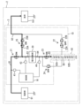
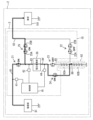
- FIG. 1 is a circuit diagram illustrating an example of an in-vehicle system including an in-vehicle control device according to the first embodiment.
- FIG. 2 is an explanatory diagram illustrating an example of an operation in which the power storage unit is charged when the first power path is in a normal state.
- FIG. 3 is an explanatory diagram illustrating an example of an operation in which power is supplied to the second power storage unit when the first power path is in a normal state.
- FIG. 4 is an explanatory diagram illustrating an example of an operation in which power from a power supply unit is voltage-converted by a voltage conversion unit and supplied to a second power path.
- FIG. 1 is a circuit diagram illustrating an example of an in-vehicle system including an in-vehicle control device according to the first embodiment.
- FIG. 2 is an explanatory diagram illustrating an example of an operation in which the power storage unit is charged when the first power path is in a normal state.
- FIG. 3 is an explanatory diagram illustrating an
- FIG. 5 is an explanatory diagram illustrating an example of a power supply operation performed by the on-board control device of the first embodiment immediately after the first power path is equal to or lower than the first threshold and the failure determination condition is met.
- FIG. 6 is an explanatory diagram illustrating an example of a power supply operation performed by the vehicle-mounted control device of the first embodiment after a certain amount of time has elapsed since the malfunction determination condition is satisfied.
- FIG. 7 is an explanatory diagram showing a modified example of the element portion.
- An in-vehicle control device for use in an in-vehicle system including a power supply unit that supplies electric power, a power storage unit different from the power supply unit, a first power path through which electric power from the power supply unit is supplied, and a second power path that is a path through which the electric power supplied from the first power path is supplied to a load side, the in-vehicle control device controlling power supply from the power storage unit, a voltage conversion unit that is provided between the second power path and the power storage unit and performs a first conversion operation of converting a voltage applied to a third power path provided on the second power path side and applying an output voltage to a fourth power path provided on the power storage unit side, and a second conversion operation of converting a voltage applied to the fourth power path and applying an output voltage to the third power path;
- a control unit that controls the voltage conversion unit; a first element portion capable of allowing a current to flow from the first power path side to the third power path side and blocking a current from flowing from the third power path side to
- the above-mentioned vehicle-mounted control measure can charge the storage unit while applying a desired voltage to the fourth power path by making the voltage conversion unit perform a first conversion operation in a state in which the first element unit allows a current to flow from the first power path to the third power path.
- the above-mentioned vehicle-mounted control measure can supply power to the second power path while applying a desired voltage to the third power path by making the voltage conversion unit perform a second conversion operation.
- this vehicle-mounted control device can adjust the charging voltage when charging the storage unit and the discharging voltage when discharging the storage unit with a simpler configuration, and in some cases, the first element unit can block the flow of current from the third power path to the first power path.
- the second element unit since the second element unit is provided and can allow a current to flow from the intermediate conductive path between the first storage unit and the second storage unit to the second power path, the second storage unit can be discharged via a path other than the path in which the voltage is adjusted by the voltage conversion unit. Furthermore, since the second element unit can block the flow of current from the second power path side to the intermediate conductive path side, in some cases, it can block the flow of current from the second power path side to the second storage unit via the second element unit. Furthermore, according to a configuration in which the second storage unit is discharged via the second element unit, the output voltage is lower than in a configuration in which the storage unit is discharged directly. Therefore, it is easy to prevent the voltage input to the load from exceeding the rated voltage of the load.
- a third element unit provided between the fourth power path and a fifth power path to which an output voltage of the storage unit is applied; a fourth element unit provided in parallel with a component in which the third element unit and the first power storage unit are connected in series, the third element unit blocks a current from flowing through itself from the fifth power path side to the fourth power path side when the third element unit is in an off state, and allows a current to flow through itself from the fifth power path side to the fourth power path side when the third element unit is in an on state; the fourth element portion blocks a current from flowing through itself from the fourth power path side to the intermediate conductive path side when the fourth element portion is in an off state, and allows a current to flow through itself from the fourth power path side to the intermediate conductive path side when the fourth element portion is in an on state; when the control unit causes the third element unit to be in an on state and the fourth element unit to be in an off state to cause the voltage conversion unit to perform the first conversion operation, power is supplied from the voltage conversion unit to the power storage unit,
- the vehicle control device can selectively supply power from the voltage conversion unit to the power storage unit, or supply power to the second power storage unit, bypassing the first power storage unit.
- the above-mentioned vehicle-mounted control device can suppress a voltage drop in the second storage unit because power is supplied to the intermediate conductive path via the first and fourth element units even if a current flows from the intermediate conductive path side to the second power path side via the second element unit. This also makes it possible to suppress a voltage rise in the first storage unit caused by a voltage drop in the second storage unit, and ultimately suppresses deterioration of the first storage unit.
- the control unit of the in-vehicle control device described in [3] makes the power supplied from the voltage conversion unit to the intermediate conductive path side via the fourth element unit greater than the power supplied from the intermediate conductive path side to the second power path side via the second element unit.
- the vehicle control device can supply a larger amount of power to the intermediate conductive path even if a current flows from the intermediate conductive path to the second power path via the second element unit. Therefore, the vehicle control device can supply power to the second power path while more reliably ensuring a charging current to the second power storage unit.
- the control unit is when the voltage of the power storage unit is less than a predetermined lower limit voltage, while keeping the third element unit in an on state and the fourth element unit in an off state, causing the voltage conversion unit to start the first conversion operation so that the voltage applied to the fourth power path becomes a first target value;
- the in-vehicle control device according to any one of [2] to [4], wherein, when the voltage of the power storage unit reaches a charging completion voltage that is equal to or higher than the lower limit voltage, the third element unit is turned off and the fourth element unit is turned on, while the voltage conversion unit is caused to perform the first conversion operation so that the voltage applied to the fourth power path becomes a second target value that is smaller than the first target value.
- the vehicle-mounted control device can charge the storage unit with power from the voltage conversion unit when the voltage of the storage unit is below the lower limit voltage, and can supply power to the second storage unit at a lower output voltage when the storage unit reaches the charging completion voltage.
- the control unit allows a current to flow from the first power path side to the third power path side in the first element unit and allows a current to flow from the intermediate conductive path side to the second power path side in the second element unit, while turning off the third element unit and turning on the fourth element unit, and causing the voltage conversion unit to perform the first conversion operation;
- the in-vehicle control device described in [5] wherein, when the voltage of the first power path is equal to or lower than the first threshold value and the failure determination condition is satisfied, the first element unit blocks current flow from the third power path side to the first power path side, and the second element unit blocks current flow from the second power path side to the intermediate conductive path side, while the control unit turns on the third element unit and turns off the fourth element unit, causing the voltage conversion unit to perform the second conversion operation.
- the above-mentioned vehicle-mounted control device can supply power from the second storage unit to the second power path via the second element unit when the voltage of the first power path drops below the first threshold value, while voltage-converting the power from the power supply unit in the voltage conversion unit and supplying it to the intermediate conductive path when the failure determination condition is not met.
- the vehicle-mounted control device meets the failure determination condition, it can cut off backflow to the first power path, while voltage-converting the power from the storage unit in the voltage conversion unit and supplying it to the second power path.
- the second element portion is configured to block current flow between the intermediate conductive path and the second power path through itself in both directions when the second element portion is in an off state, and to allow current to flow from the intermediate conductive path to the second power path through itself when the second element portion is in an on state;
- the control unit controls at least the second element unit to be turned on and off, 10.
- the in-vehicle control device wherein, when the voltage of the first power path is equal to or lower than the first threshold value, when a switch occurs from a state in which the failure determination condition is not satisfied to a state in which the failure determination condition is satisfied, the control unit maintains the second element unit in an on state before and after the switch, and after the switch, while blocking current flow from the third power path side to the first power path side in the first element unit, the control unit turns the third element unit in an on state, turns the fourth element unit in an off state, and causes the voltage conversion unit to perform the second conversion operation, and when the voltage conversion unit satisfies a predetermined operating condition after the switch, the control unit switches the second element unit to an off state.
- the vehicle control device can quickly supply power from the second storage unit to the second power path by turning on the second element unit.
- the voltage of the first power path is equal to or lower than the first threshold and the failure determination condition is switched from a state in which it is not satisfied to a state in which it is satisfied, after the switchover, power whose voltage has been adjusted by the second conversion operation can be supplied to the second power path via the third power path while preventing backflow to the first power path.
- the vehicle control device can maintain the second element unit in the on state before and after the switchover, even if the rise of the output of the voltage conversion unit is slow after the switchover, the supply of power from the second storage unit to the second power path via the second element unit can be continued. Furthermore, this vehicle control device can narrow down the discharge path to the third power path out of the path of the second element unit and the third power path by switching the second element unit to the off state when the voltage conversion unit satisfies a predetermined operating condition after switching.
- the failure determination condition includes a condition in which a current flows from the third power path side to the first power path side via the first element portion, when a voltage of the first power path is equal to or lower than the first threshold value and no current flows from the third power path side to the first power path side via the first element unit, the control unit turns off the third element unit and turns on the fourth element unit, causes the voltage conversion unit to perform the first conversion operation while allowing a current to flow from the first power path side to the third power path side in the first element unit, and allows a current to flow from the intermediate conductive path side to the second power path side in the second element unit,
- the in-vehicle control device described in [6] or [7] wherein when a current flows from the third power path side to the first power path side via the first element unit when the voltage of the first power path is equal to or lower than the first threshold value, the control unit turns on the third element unit, turns off the fourth element unit, and causes the voltage conversion unit to perform the second conversion operation while blocking the flow of current from the third
- the vehicle control device can make the voltage conversion unit perform the first conversion operation to charge the second power storage unit after confirming that no current flows to the first power path through the first element unit, i.e., that there is a high possibility that a ground fault has not occurred in the first power path.
- the vehicle control device can then perform discharging through the second element unit in parallel with the supply of power to the second power storage unit through the first conversion operation.
- the first element unit can block the flow of current to the first power path, thereby preventing the influence of the ground fault from reaching the third power path.
- the failure determination condition includes a condition that a voltage of the first power path is equal to or lower than a second threshold value that is lower than the first threshold value, when the voltage of the first power path is equal to or less than the first threshold value and exceeds the second threshold value, the control unit turns off the third element unit and turns on the fourth element unit to cause the voltage conversion unit to perform the first conversion operation while allowing a current to flow from the first power path side to the third power path side in the first element unit, and allows a current to flow from the intermediate conductive path side to the second power path side in the second element unit;
- the in-vehicle control device according to any one of [6] to [8], wherein, when the voltage of the first power path is equal to or lower than the second threshold value, the control unit turns on the third element unit, turns off the fourth element unit, and causes the voltage conversion unit to perform the second conversion operation while blocking current flow from the third power path side to the first power path side in the first element unit.
- the vehicle control device can make the voltage conversion unit perform the first conversion operation to charge the second power storage unit after confirming that the voltage of the first power path exceeds the second threshold, i.e., that the voltage of the first power path is not too low.
- the vehicle control device can then perform discharging via the second element unit in parallel with the supply of power to the second power storage unit by the first conversion operation.
- the first element unit can block the flow of current to the first power path, so that even if a ground fault occurs in the first power path, the influence of the ground fault on the third power path can be suppressed.
- the malfunction determination condition includes a condition in which a predetermined malfunction signal is given to the vehicle-mounted control device from an external device different from the vehicle-mounted control device, when the voltage of the first power path is equal to or lower than the first threshold value and the failure signal is not provided from the external device, the control unit turns off the third element unit and turns on the fourth element unit to cause the voltage conversion unit to perform the first conversion operation while allowing a current to flow from the first power path side to the third power path side in the first element unit, and allows a current to flow from the intermediate conductive path side to the second power path side in the second element unit,
- the in-vehicle control device according to any one of [6] to [9], wherein, when the voltage of the first power path is equal to or lower than the first threshold value and the failure signal is given from the external device, the control unit turns on the third element unit, turns off the fourth element unit, and causes the voltage conversion unit to perform the second conversion operation while blocking current flow from the third power path side to the first power path side in the first element unit.
- the vehicle control device can confirm that no fault signal has been given from an external device and then have the voltage conversion unit perform the first conversion operation to charge the second power storage unit.
- the vehicle control device can discharge through the second element unit in parallel with the supply of power to the second power storage unit by the first conversion operation.
- the first element unit can block current from flowing to the first power path while causing the voltage conversion unit to perform the second conversion operation. Therefore, even if a ground fault or the like occurs in the first power path when a fault signal is generated, the influence of the fault can be suppressed and power whose voltage has been adjusted by the voltage conversion unit can be supplied to the second power path.
- An in-vehicle control device as described in any one of [1] to [10], comprising a fifth element unit capable of allowing current to flow from the third power path side to the second power path side and blocking current from flowing from the second power path side to the third power path side.
- the vehicle control device can supply power to the second power path while applying a desired voltage to the third power path by causing the voltage conversion unit to perform a second conversion operation while the fifth element unit is allowing current to flow from the third power path to the second power path.
- FIG. 1 shows an in-vehicle system 2.
- the in-vehicle system 2 in Fig. 1 includes an in-vehicle power supply system 3 and a load 101.
- the in-vehicle system 2 is a system that supplies power to the load 101 by the in-vehicle power supply system 3 to operate the load 101.
- the load 101 is an electrical component mounted on the vehicle.
- the load 101 operates by receiving power supplied from the vehicle power supply system 3.
- Various well-known vehicle-mounted components may be used as the load 101.
- the load 101 may have multiple electrical components or may be a single electrical component.
- the vehicle power supply system 3 is a system that supplies power to the load 101.
- the vehicle power supply system 3 supplies power to the load 101 using the power supply unit 91 or the power storage unit 92 as a power supply source.
- the vehicle power supply system 3 can supply power to the load 101 from the power supply unit 91, and can supply power to the load 101 from the power storage unit 92 when the power supply from the power supply unit 91 is interrupted due to, for example, a malfunction.
- the power storage unit 92 may be used as a power supply source that supplies power to the load 101 when the power supply from the power supply unit 91 to the load 101 is not interrupted.
- the vehicle power supply system 3 includes a power supply unit 91, a power storage unit 92, and an in-vehicle control device 10.
- a first power path 81, a second power path 82, a third power path 83, a fourth power path 84, a fifth power path 85, and the like are configured as parts of the in-vehicle control device 10.
- any of the first power path 81, the second power path 82, the third power path 83, the fourth power path 84, and the fifth power path 85 may not be part of or entirely part of the in-vehicle control device 10.
- the power supply unit 91 is an on-board power supply capable of supplying power to the load 101.
- the power supply unit 91 is configured as a known on-board power storage unit such as a lead battery.
- the power supply unit 91 may be configured with a battery other than a lead battery (e.g., a lithium ion battery or other battery), and may have a power supply means other than a battery instead of or in addition to a battery.
- the positive terminal of the power supply unit 91 is electrically connected to the first power path 81 in a configuration in which it is shorted to the first power path 81.
- the negative terminal of the power supply unit 91 is electrically connected to the ground in a configuration in which it is shorted to the ground.
- the power supply unit 91 applies a constant DC voltage to the first power path 81.
- the voltage applied by the power supply unit 91 to the first power path 81 may vary slightly from the constant value.
- the storage unit 92 is a power source different from the power source unit 91.
- the storage unit 92 is a power source that becomes a power supply source at least when the power supply from the power source unit 91 is interrupted.
- the storage unit 92 is composed of a known storage means such as an electric double layer capacitor (EDLC).
- EDLC electric double layer capacitor
- the storage unit 92 may be composed of a capacitor other than an electric double layer capacitor, and may include other storage means (such as a battery) instead of or in addition to a capacitor.
- the positive terminal of the storage unit 92 is electrically connected to the fifth power path 85 in a configuration in which it is shorted to the fifth power path 85.
- the negative terminal of the storage unit 92 is electrically connected to the ground in a configuration in which it is shorted to the ground.
- the output voltage of the storage unit 92 (the voltage applied to the fifth power path 85 by the storage unit 92) may be larger, smaller, or approximately the same as the output voltage of the power source unit 91 (the voltage applied to the first power path 81 by the power source unit 91).
- the power storage unit 92 has a first power storage unit 92A and a second power storage unit 92B.
- the second power storage unit 92B is arranged at a lower potential side than the first power storage unit 92A and is connected in series to the first power storage unit 92A.
- the positive electrode side terminal of the first power storage unit 92A constitutes the positive electrode side terminal of the power storage unit 92.
- the negative electrode side terminal of the first power storage unit 92A is short-circuited to the positive electrode side terminal of the second power storage unit 92B and is electrically connected to the positive electrode side terminal of the second power storage unit 92B.
- the negative electrode side terminal of the second power storage unit 92B constitutes the negative electrode side terminal of the power storage unit 92.
- voltage refers to a voltage relative to a ground potential (e.g., 0 V) and is the potential difference with respect to the ground potential.
- a ground potential e.g., 0 V
- the voltage applied to the first power path 81 is the potential difference between the potential of the first power path 81 and the ground potential.
- the output voltage of the power supply unit 91 is applied to the first power path 81.
- the first power path 81 constitutes a part or the whole of the power supply path between the power supply unit 91 and the first element unit 21.
- One end of the first power path 81 is electrically connected to the positive terminal of the power supply unit 91 in a configuration in which it is short-circuited to the positive terminal of the power supply unit 91.
- the other end of the first power path 81 is electrically connected to one end of the first element unit 21 (in the example of FIG. 1, the source terminal which is one end of the semiconductor switch constituting the first element unit 21) in a configuration in which it is short-circuited to the one end.
- the first power path 81 may be provided with a relay or a fuse.
- the first power path 81 functions to, for example, make the positive terminal of the power supply unit 91 and one end of the first element unit 21 at the same potential or approximately the same potential.
- the second power path 82 is a path that supplies the power supplied from the first power path 81 to the load 101.
- the second power path 82 constitutes a part or all of the power supply path between the fifth element section 25 and the load 101.
- One end of the second power path 82 is electrically connected to the other end of the fifth element section 25 (in the example shown in FIG. 1, the drain terminal that is the other end of the semiconductor switch 25B).
- the other end of the second power path 82 is electrically connected to the load 101 in a configuration in which it is short-circuited to one end of the load 101.
- the second other end of the second power path 82 is electrically connected to the other end of the second element section 22 in a configuration in which it is short-circuited to the other end of the second element section 22 (in the example shown in FIG. 1, the drain terminal that is the other end of the semiconductor switch 22B).
- a relay or a fuse may be provided in the second power path 82.
- the second power path 82 functions, for example, to bring the other end of the fifth element section 25, the other end of the second element section 22, and one end of the load 101 to the same potential or approximately the same potential.
- the third power path 83 is a power path different from the first power path 81 and the second power path 82.
- the third power path 83 is provided on the first power path 81 side of the voltage conversion unit 30 and on the second power path 82 side of the voltage conversion unit 30.
- One end of the third power path 83 is electrically connected to the other end of the first element unit 21 in a configuration shorted to the other end of the first element unit 21 (in the example of FIG. 1, the drain terminal that is the other end of the semiconductor switch that constitutes the first element unit 21).
- the other end of the third power path 83 is electrically connected to one end of the voltage conversion unit 30 in a configuration shorted to one end of the voltage conversion unit 30.
- the second other end of the third power path 83 is electrically connected to one end of the fifth element unit 25 in a configuration shorted to one end of the fifth element unit 25 (in the example of FIG. 1, the drain terminal that is one end of the semiconductor switch 25A).
- the third power path 83 functions, for example, to make the other end of the first element section 21, one end of the fifth element section 25, and one end of the voltage conversion section 30 have the same potential or approximately the same potential.
- the fourth power path 84 is a power path different from the first power path 81, the second power path 82, and the third power path 83.
- the fourth power path 84 is provided on the storage unit 92 side of the voltage conversion unit 30.
- One end of the fourth power path 84 is electrically connected to the other end of the voltage conversion unit 30 in a configuration in which it is shorted to the other end of the voltage conversion unit 30.
- the other end of the fourth power path 84 is electrically connected to one end of the third element unit 23 in a configuration in which it is shorted to one end of the third element unit 23 (in the example of FIG. 1, a source terminal that is one end of the semiconductor switch that constitutes the third element unit 23).
- the second other end of the fourth power path 84 is electrically connected to one end of the fourth element unit 24 in a configuration in which it is shorted to one end of the fourth element unit 24 (in the example of FIG. 1, a drain terminal that is one end of the semiconductor switch that constitutes the fourth element unit 24).
- the fourth power path 84 functions, for example, to make the other end of the voltage conversion unit 30, one end of the third element unit 23, and one end of the fourth element unit 24 have the same potential or approximately the same potential.
- the fifth power path 85 is a power path different from the first power path 81, the second power path 82, the third power path 83, and the fourth power path 84.
- One end of the fifth power path 85 is electrically connected to the other end of the third element portion 23 in a configuration shorted to the other end of the third element portion 23 (in the example shown in FIG. 1, the drain terminal which is the other end of the semiconductor switch constituting the third element portion 23).
- the other end of the fifth power path 85 is electrically connected to the positive terminal of the storage unit 92 in a configuration shorted to the positive terminal of the storage unit 92.
- the fifth power path 85 functions, for example, to make the other end of the third element portion 23 and the positive terminal of the storage unit 92 have the same potential or approximately the same potential.
- An intermediate conductive path 89 is provided between the first storage unit 92A and the second storage unit 92B.
- One end of the intermediate conductive path 89 is electrically connected to the negative terminal of the first storage unit 92A in a configuration in which it is short-circuited to the negative terminal of the first storage unit 92A.
- the other end of the intermediate conductive path 89 is electrically connected to the positive terminal of the second storage unit 92B in a configuration in which it is short-circuited to the positive terminal of the second storage unit 92B.
- the second other end of the intermediate conductive path 89 is electrically connected to the other end of the fourth element unit 24 (in the example shown in FIG.
- the intermediate conductive path 89 functions to, for example, bring the negative terminal of the first storage unit 92A, the positive terminal of the second storage unit 92B, the other end of the fourth element unit 24, and one end of the second element unit 22 to the same potential or approximately the same potential.
- the vehicle control device 10 is used in the vehicle system 2, and is a device that controls power supply from the power storage unit 92.
- the vehicle control device 10 is a backup control device that can control a backup operation that outputs power from the power storage unit 92.
- the vehicle control device 10 includes a first power path 81, a second power path 82, a third power path 83, a fourth power path 84, a fifth power path 85, a control unit 16, a voltage conversion unit 30, a first element unit 21, a second element unit 22, a third element unit 23, a fourth element unit 24, a fifth element unit 25, voltage detection units 41, 43, 44, and the like.
- the first element section 21 is composed of one semiconductor switch.
- the second element section 22 is composed of two semiconductor switches 22A and 22B.
- the third element section 23 is composed of one semiconductor switch.
- the fourth element section 24 is composed of one semiconductor switch.
- the fifth element section 25 is composed of two semiconductor switches 25A and 25B.
- the semiconductor switches constituting the first element section 21, the second element section 22, the third element section 23, the fourth element section 24, and the fifth element section 25 are all composed of N-channel type FETs (Field Effect Transistors).
- the first element section 21 is configured to allow current to flow from the first power path 81 side to the third power path 83 side (i.e., the voltage conversion unit 30 side) and to block current flow from the third power path 83 side (i.e., the voltage conversion unit 30 side) to the first power path 81 side.
- the drain of the first element section 21 is electrically connected to be shorted to the third power path 83
- the source of the first element section 21 is electrically connected to be shorted to the first power path 81.
- the second element portion 22 is capable of allowing current to flow from the intermediate conductive path 89 side to the second power path 82 side.
- the second element portion 22 is capable of blocking current from flowing from the second power path 82 side to the intermediate conductive path 89 side.
- the semiconductor switches 22A and 22B constituting the second element portion 22 are connected in opposite directions to each other. In the example of Figure 1, the drain of semiconductor switch 22A is shorted to the intermediate conductive path 89, the drain of semiconductor switch 22B is shorted to the second power path 82, and the source of semiconductor switch 22A is shorted to the source of semiconductor switch 22B.
- the second element portion 22 is in the off state when both semiconductor switches 22A and 22B are in the off state.
- the second element portion 22 When the second element portion 22 is in the off state, current flow through the second element portion 22 is blocked in both directions, and both the flow of current from the second power path 82 side to the intermediate conductive path 89 side through the second element portion 22 and the flow of current from the intermediate conductive path 89 side to the second power path 82 side through the second element portion 22 are blocked.
- the second element portion 22 is in the on state when both the semiconductor switches 22A and 22B are in the on state.
- current flow through the second element portion 22 When the second element portion 22 is in the on state, current flow through the second element portion 22 is permitted in both directions, and both the flow of current from the second power path 82 side to the intermediate conductive path 89 side and the flow of current from the intermediate conductive path 89 side to the second power path 82 side are permitted.
- the third element 23 is provided between the fourth power path 84 and the fifth power path 85. That is, the third element 23 is provided between the voltage conversion unit 30 and the storage unit 92. When the third element 23 is in an off state, it blocks current from flowing from the fifth power path 85 to the fourth power path 84 through itself. When the third element 23 is in an on state, it allows current to flow from the fifth power path 85 to the fourth power path 84 through itself. When the third element 23 is in an on state, current is allowed to flow in both directions through the third element 23. When the third element 23 is in an on state, the voltage of the fourth power path 84 and the voltage of the storage unit 92 are the same. That is, when the third element 23 is in an on state, the output voltage of the storage unit 92 is applied to the fourth power path 84.
- the fourth element 24 is provided in parallel with the structure in which the third element 23 and the first storage unit 92A are connected in series. When the fourth element 24 is in the off state, it blocks current from flowing through itself from the fourth power path 84 to the intermediate conductive path 89. When the fourth element 24 is in the on state, it allows current to flow through itself from the fourth power path 84 to the intermediate conductive path 89. When the fourth element 24 is in the on state, current is allowed to flow in both directions through the fourth element 24. When the fourth element 24 is in the on state, the voltage of the fourth power path 84 and the voltage of the second storage unit 92B are the same. In other words, when the fourth element 24 is in the on state, the output voltage of the second storage unit 92B is applied to the fourth power path 84.
- the fifth element section 25 is capable of allowing a current to flow from the third power path 83 side (i.e., the voltage conversion section 30 side) to the second power path 82 side.
- the fifth element section 25 is capable of blocking a current from flowing from the second power path 82 side to the third power path 83 side (i.e., the voltage conversion section 30 side).
- the semiconductor switches 25A and 25B constituting the fifth element section 25 are connected in the opposite directions to each other. In the example of FIG. 1, the drain of semiconductor switch 25A is shorted to the third power path 83, the drain of semiconductor switch 25B is shorted to the second power path 82, and the source of semiconductor switch 25A is shorted to the source of semiconductor switch 25B.
- the fifth element section 25 is in the off state when both semiconductor switches 25A and 25B are in the off state.
- the current passing through the fifth element 25 is blocked in both directions, and both the current flow from the second power path 82 side to the third power path 83 side (i.e., the voltage conversion unit 30 side) and the current flow from the third power path 83 side (the voltage conversion unit 30 side) to the second power path 82 side are blocked.
- both the semiconductor switches 25A and 25B are in the on state.
- the current passing through the fifth element 25 is allowed in both directions, and both the current flow from the second power path 82 side to the third power path 83 side (i.e., the voltage conversion unit 30 side) and the current flow from the third power path 83 side (i.e., the voltage conversion unit 30 side) to the second power path 82 side are allowed.
- the voltage conversion unit 30 is configured with a known voltage conversion circuit such as a DC-DC converter. In the example of FIG. 1, the voltage conversion unit 30 performs voltage conversion between the third power path 83 and the fourth power path 84.
- the voltage conversion unit 30 is a device that performs a first conversion operation of voltage conversion to step up or step down the voltage applied to the third power path 83 and apply the output voltage to the fourth power path 84, and a second conversion operation of voltage conversion to step up or step down the voltage applied to the fourth power path 84 and apply the output voltage to the third power path 83. In this way, the voltage conversion unit 30 performs voltage conversion in both directions. The operation of the voltage conversion unit 30 is controlled by the control unit 16.
- the control unit 16 controls the first element unit 21, the second element unit 22, the third element unit 23, the fourth element unit 24, the fifth element unit 25, and the voltage conversion unit 30.
- the control unit 16 is configured to include an information processing device having information processing functions, calculation functions, control functions, etc.
- the device that controls the first element unit 21, the second element unit 22, the third element unit 23, the fourth element unit 24, the fifth element unit 25, and the voltage conversion unit 30 may be a single common device, or may be configured by multiple devices.
- the voltage detection unit 41 is a circuit that provides the control unit 16 with a detection value (e.g., an analog voltage value) that can identify the value of the voltage applied to the first power path 81.
- the voltage detection unit 43 is a circuit that provides the control unit 16 with a detection value (e.g., an analog voltage value) that can identify the value of the voltage applied to the third power path 83.
- the voltage detection unit 44 is a circuit that provides the control unit 16 with a detection value (e.g., an analog voltage value) that can identify the value of the voltage applied to the fourth power path 84.
- the control unit 16 can determine the output voltage of the power storage unit 92 based on the detection value of the voltage detection unit 44 when the third element unit 23 is in the ON state and the fourth element unit 24 is in the OFF state.
- the control unit 16 can determine the output voltage of the second power storage unit 92B based on the detection value of the voltage detection unit 44 when the third element unit 23 is in the OFF state and the fourth element unit 24 is in the ON state.
- the control unit 16 turns on the first element unit 21 and the fifth element unit 25. As a result, as shown in FIG. 2, power from the power supply unit 91 is supplied to the second power path 82 via the first element unit 21 and the fifth element unit 25. Note that the control unit 16 maintains the second element unit 22 in the off state even when the vehicle is started.
- the control unit 16 can know that the vehicle has started by receiving a signal indicating the on/off state of the start switch, or by receiving a signal output from an external ECU when the vehicle is started.
- the start switch is an ignition switch, a power switch, or the like.
- the control unit 16 turns on the third element unit 23 and turns off the fourth element unit 24, and causes the voltage conversion unit 30 to perform a first conversion operation so that the voltage applied to the fourth power path 84 becomes a first target value.
- the power from the power supply unit 91 is voltage converted by the voltage conversion unit 30 and supplied to the storage unit 92, and the storage unit 92 is charged.
- the lower limit voltage is 0V or higher.
- the first target value is a value greater than the lower limit voltage. The first target value may be greater than the rated voltage of the load 101.
- the control unit 16 switches the third element unit 23 to the OFF state, switches the fourth element unit 24 to the ON state, and switches the target voltage of the voltage conversion unit 30 from the first target value to the second target value.
- the control unit 16 switches the third element unit 23 to the OFF state and the fourth element unit 24 to the ON state, and causes the voltage conversion unit 30 to perform a first conversion operation so that the voltage applied to the fourth power path 84 reaches a second target value that is smaller than the first target value.
- the power from the power supply unit 91 is voltage-converted by the voltage conversion unit 30 and supplied to the second storage unit 92B via the fourth element unit 24.
- the control unit 16 waits while maintaining this state.
- the charging completion voltage may be the same as the lower limit voltage, or may be a value greater than the lower limit voltage.
- the charging completion voltage may be the same as the first target value, or may be a value smaller than the first target value.
- the control unit 16 may charge the second power storage unit 92B without charging the entire power storage unit 92.
- the control unit 16 may cause the voltage conversion unit 30 to perform a first conversion operation while turning off the third element unit 23 and turning on the fourth element unit 24 so that the voltage applied to the fourth power path 84 becomes a second target value that is smaller than the first target value.
- the control unit 16 When the voltage of the first power path 81 exceeds the first threshold and is less than an overvoltage threshold that is greater than the first threshold, the control unit 16 performs the above-mentioned operations (specifically, the operation of supplying power to the second power path 82 via the fifth element unit 25, and the operation of supplying power to the power storage unit 92 or the second power storage unit 92B).
- the control unit 16 When the voltage of the first power path 81 is equal to or greater than a predetermined overvoltage threshold, the control unit 16 turns the first element unit 21 on, the second element unit 22 on, the third element unit 23 off, the fourth element unit 24 on, and the fifth element unit 25 off, causing the voltage conversion unit 30 to perform a first conversion operation.
- the control unit 16 makes the power supplied from the voltage conversion unit 30 to the intermediate conductive path 89 side via the fourth element unit 24 greater than the power supplied to the second power path 82 side via the second element unit 22.
- the control unit 16 turns the first element unit 21 on, the second element unit 22 on, the third element unit 23 off, the fourth element unit 24 on, and the fifth element unit 25 off, causing the voltage conversion unit 30 to perform a first conversion operation.
- the power from the power supply unit 91 is voltage converted by the voltage conversion unit 30 and supplied to the second power path 82 via the fourth element unit 24 and the second element unit 22.
- the control unit 16 makes the power supplied from the voltage conversion unit 30 to the intermediate conductive path 89 side via the fourth element unit 24 greater than the power supplied to the second power path 82 side via the second element unit 22.
- the control unit 16 turns the first element unit 21 to the OFF state, the second element unit 22 to the OFF state, the third element unit 23 to the ON state, the fourth element unit 24 to the OFF state, and the fifth element unit 25 to the ON state, causing the voltage conversion unit 30 to perform a second conversion operation.
- the power from the power storage unit 92 is voltage converted by the voltage conversion unit 30 and supplied to the second power path 82 via the fifth element unit 25.
- the control unit 16 maintains the second element unit 22 in the ON state before and after the switchover when the failure determination condition is switched from a state in which it is not satisfied to a state in which it is satisfied.
- power from the second power storage unit 92B is supplied to the second power path 82 via the second element unit 22.
- the control unit 16 turns the first element unit 21 to the OFF state, the second element unit 22 to the ON state, the third element unit 23 to the ON state, the fourth element unit 24 to the OFF state, and the fifth element unit 25 to the OFF state, causing the voltage conversion unit 30 to perform the second conversion operation.
- the fifth element unit 25 is switched to the ON state.
- the power from the power storage unit 92 is voltage converted by the voltage conversion unit 30 and supplied to the second power path 82 via the fifth element unit 25.
- the control unit 16 also switches the second element unit 22 to the off state.
- the specified operating condition may be, for example, the output voltage of the voltage conversion unit 30 reaching a predetermined operating start voltage, or a specified time having elapsed since the above-mentioned switching occurred, or another condition.
- the above-mentioned failure determination condition may include a condition in which a current flows from the voltage conversion unit 30 side to the first power path 81 side via the first element unit 21.
- the failure determination condition may include a condition in which the voltage of the first power path 81 becomes equal to or lower than a second threshold value that is lower than the first threshold value.
- the failure determination condition may include a condition in which a predetermined failure signal is given to the in-vehicle control device 10 from an external device different from the in-vehicle control device 10.
- the in-vehicle control device 10 can charge the power storage unit 92 while applying a desired voltage to the fourth power path 84 by making the voltage conversion unit 30 perform the first conversion operation in a state in which the first element unit 21 allows a current to flow from the first power path 81 side to the third power path 83 side.
- the in-vehicle control device 10 can supply power to the second power path 82 while applying a desired voltage to the third power path 83 by making the voltage conversion unit 30 perform the second conversion operation in a state in which the fifth element unit 25 allows a current to flow from the third power path 83 side to the second power path 82 side.
- the in-vehicle control device 10 can adjust the charging voltage when charging the power storage unit 92 and the discharging voltage when discharging the power storage unit 92 with a simpler configuration, and in some cases, the first element unit 21 can block the current from flowing from the third power path 83 side to the first power path 81 side. Furthermore, since the second element unit 22 is provided and can allow a current to flow from the intermediate conductive path 89 between the first storage unit 92A and the second storage unit 92B to the second power path 82, the second storage unit 92B can be discharged via a path other than the path in which the voltage is adjusted by the voltage conversion unit 30.
- the second element unit 22 can block a current from flowing from the second power path 82 to the intermediate conductive path 89, in some cases, it can block a current from flowing from the second power path 82 to the second storage unit 92B via the second element unit 22. Furthermore, according to the configuration in which the second storage unit 92B is discharged via the second element unit 22, the output voltage is lowered compared to the configuration in which the storage unit 92 is directly discharged. Therefore, it is easy to prevent the voltage input to the load 101 from exceeding the rated voltage of the load 101.
- the vehicle control device 10 can selectively supply power from the voltage conversion unit 30 to the power storage unit 92, or supply power to the second power storage unit 92B, bypassing the first power storage unit 92A.
- the vehicle control device 10 is able to suppress a voltage drop in the second power storage unit 92B because power is supplied to the intermediate conductive path 89 via the first element unit 21 and the fourth element unit 24. This also makes it possible to suppress a voltage rise in the first power storage unit 92A caused by a voltage drop in the second power storage unit 92B, and thus makes it possible to suppress deterioration of the first power storage unit 92A.
- the vehicle control device 10 can supply a larger amount of power to the intermediate conductive path 89 even if a current flows from the intermediate conductive path 89 to the second power path 82 via the second element section 22. Therefore, the vehicle control device 10 can supply power to the second power path 82 while more reliably ensuring a charging current to the second power storage section 92B.
- the vehicle control device 10 can charge the power storage unit 92 with power from the voltage conversion unit 30, and when the power storage unit 92 reaches the charging completion voltage, can supply power to the second power storage unit 92B at a lower output voltage.
- the vehicle control device 10 can supply power from the second storage unit 92B to the second power path 82 via the second element unit 22, while converting the voltage of the power from the power supply unit 91 in the voltage conversion unit 30 and supplying it to the intermediate conductive path 89 side, when the failure determination condition is not met.
- the vehicle control device 10 can cut off backflow to the first power path 81, while converting the voltage of the power from the storage unit 92 in the voltage conversion unit 30 and supplying it to the second power path 82.
- the vehicle control device 10 can quickly supply power from the second storage unit 92B to the second power path 82 by turning on the second element unit 22.
- the vehicle control device 10 can supply power whose voltage has been adjusted by the second conversion operation to the second power path 82 via the third power path 83 after the switchover while preventing backflow to the first power path 81.
- the vehicle control device 10 can maintain the second element unit 22 in the on state before and after the switchover, the supply of power from the second storage unit 92B to the second power path 82 via the second element unit 22 can be continued even if the rise of the output of the voltage conversion unit 30 is slow after the switchover. Furthermore, when the voltage conversion unit 30 satisfies a predetermined operating condition after switching, the vehicle control device 10 switches the second element unit 22 to the off state, thereby narrowing down the discharge path to the third power path 83 out of the path of the second element unit 22 and the third power path 83.
- the failure determination condition includes a condition in which a current flows from the voltage conversion unit 30 side to the first power path 81 side via the first element unit 21
- the vehicle control device 10 can confirm that no current flows to the first power path 81 side via the first element unit 21, that is, that there is a high possibility that a ground fault has not occurred in the first power path 81, and then cause the voltage conversion unit 30 to perform a first conversion operation to charge the second storage unit 92B. Then, this vehicle control device 10 can discharge via the second element unit 22 in parallel with the supply of power to the second storage unit 92B side by the first conversion operation.
- the first element unit 21 blocks the current from flowing to the first power path 81 side, and the influence of the ground fault can be prevented from extending to the third power path 83 side. Then, by having the voltage conversion unit 30 perform the second conversion operation, it is possible to supply power whose voltage has been adjusted by the voltage conversion unit 30 to the second power path 82 while suppressing the influence of the ground fault.
- the failure determination condition includes a condition in which the voltage of the first power path 81 is equal to or lower than a second threshold value that is lower than the first threshold value
- the vehicle control device 10 can make the voltage conversion unit 30 perform the first conversion operation and charge the second power storage unit 92B after confirming that the voltage of the first power path 81 exceeds the second threshold value, i.e., that the voltage of the first power path 81 is not too low. Then, the vehicle control device 10 can perform discharging via the second element unit 22 in parallel with the supply of power to the second power storage unit 92B side by the first conversion operation.
- the first element unit 21 can block the flow of current to the first power path 81 side, so that even if a ground fault occurs in the first power path 81, the influence of the ground fault can be suppressed from extending to the third power path 83 side. Then, by having the voltage conversion unit 30 perform the second conversion operation, it is possible to supply power whose voltage has been adjusted by the voltage conversion unit 30 to the second power path 82 while suppressing the effects of a voltage drop in the first power path 81.
- the failure determination condition includes a condition in which a predetermined failure signal is given to the in-vehicle control device 10 from an external device different from the in-vehicle control device 10.
- the in-vehicle control device 10 can confirm that a failure signal has not been given from the external device and then have the voltage conversion unit 30 perform the first conversion operation to charge the second storage unit 92B.
- the in-vehicle control device 10 can then discharge through the second element unit 22 in parallel with the supply of power to the second storage unit 92B side by the first conversion operation.
- the voltage conversion unit 30 can perform the second conversion operation while blocking the flow of current to the first power path 81 side in the first element unit 21. Therefore, even if a ground fault or the like occurs on the first power path 81 when a fault signal is generated, the effects of this can be suppressed and power whose voltage has been adjusted by the voltage conversion unit 30 can be supplied to the second power path 82.
- the vehicle control device 10 can supply power to the second power path 82 while applying a desired voltage to the third power path 83 by causing the voltage conversion unit 30 to perform the second conversion operation while the fifth element unit 25 allows current to flow from the voltage conversion unit 30 to the second power path 82.
- the power storage unit 92 is provided outside the vehicle control device 10, but the power storage unit 92 may be included in the vehicle control device 10.
- the fifth element portion 25 does not have to be provided. In other words, no element needs to be interposed between the third power path 83 and the second power path 82.
- the third power path 83 and the second power path 82 may be configured to be short-circuited.
- a single FET is provided in the first element portion 21, but this is not limited to this example.
- the configuration of FIG. 7(A) may be applied, and the first element portion 21 may be configured only by the diode 191.
- the conductive path 181A may be electrically connected to the first power path 81, and the conductive path 181B may be the third power path 83.
- the configuration of FIG. 7(B) may be applied, and the first element portion 21 may be a switch portion in which a switch element 192A (e.g., a FET) and a diode 192B are provided in series.
- the conductive path 182A may be electrically connected to the first power path 81, and the conductive path 182B may be the third power path 83.
- the configuration of FIG. 7(D) may be applied, and the first element portion 21 may be a switch portion 194 consisting of a known semiconductor switch or mechanical relay other than a FET.
- the conductive path 184A may be electrically connected to the first power path 81, and the conductive path 184B may be the third power path 83.
- the configuration of FIG. 7(E) may be applied, and the first element portion 21 may be configured with two semiconductor switches 195A and 195B.
- the conductive path 185A may be electrically connected to the first power path 81, and the conductive path 185B may be the third power path 83.
- the two semiconductor switches 195A and 195B may be, for example, FETs, and may be arranged so that their sources are short-circuited.
- FIG. 7(A) may be applied and the second element section 22 may be configured only by the diode 191.
- the conductive path 181A may be electrically connected to the fourth power path 84
- the conductive path 181B may be electrically connected to the second power path 82.
- the configuration of FIG. 7(B) may be applied and the second element section 22 may be a switch section in which a switch element 192A (e.g., a FET) and a diode 192B are provided in series.
- the conductive path 182A may be electrically connected to the fourth power path 84, and the conductive path 182B may be electrically connected to the second power path 82.
- the configuration of FIG. 7(C) may be applied and the second element section 22 may be configured only by the switch element 193 (e.g., a FET).
- the conductive path 183A may be electrically connected to the fourth power path 84, and the conductive path 183B may be electrically connected to the second power path 82.
- the configuration of FIG. 7(D) may be applied, and the second element section 22 may be a switch section 194 made of a known semiconductor switch or mechanical relay other than an FET.
- the conductive path 184A may be electrically connected to the fourth power path 84, and the conductive path 184B may be electrically connected to the second power path 82.
- a single FET is provided in the third element section 23, but this is not limited to the example.
- the configuration of FIG. 7(D) may be applied, and the third element section 23 may be a switch section 194 consisting of a known semiconductor switch or mechanical relay other than a FET.
- the conductive path 184A may be the fourth power path 84, and the conductive path 184B may be the fifth power path 85.
- the configuration of FIG. 7(E) may be applied, and the third element section 23 may be composed of two semiconductor switches 195A and 195B.
- the conductive path 185A may be the fourth power path 84, and the conductive path 185B may be the fifth power path 85.
- the two semiconductor switches 195A and 195B may be, for example, FETs, and may be arranged so that their sources are short-circuited.
- a single FET is provided in the fourth element section 24, but this is not limited to the example.
- the configuration of FIG. 7(D) may be applied, and the fourth element section 24 may be a switch section 194 consisting of a known semiconductor switch or mechanical relay other than a FET.
- the conductive path 184A may be electrically connected to the fourth power path 84
- the conductive path 184B may be electrically connected to the intermediate conductive path 89.
- the configuration of FIG. 7(E) may be applied, and the fourth element section 24 may be composed of two semiconductor switches 195A and 195B.
- the conductive path 185A may be electrically connected to the fourth power path 84, and the conductive path 185B may be electrically connected to the intermediate conductive path 89.
- the two semiconductor switches 195A and 195B may be, for example, FETs, and may be arranged so that their sources are short-circuited.
- the fifth element section 25 is composed of two FETs, but as shown in FIG. 7A, the fifth element section 25 may be composed of only a diode 191.
- the conductive path 181A may be electrically connected to the third power path 83, and the conductive path 181B may be electrically connected to the second power path 82.
- the fifth element section 25 may be a switch section in which a switch element 192A (e.g., a FET) and a diode 192B are provided in series.
- the conductive path 182A may be electrically connected to the third power path 83, and the conductive path 182B may be electrically connected to the second power path 82.
- the fifth element section 25 may be composed of only a switch element 193 (e.g., a FET).
- the conductive path 183A may be electrically connected to the third power path 83, and the conductive path 183B may be electrically connected to the second power path 82.
- the fifth element portion 25 may be a switch portion 194 made of a known semiconductor switch or mechanical relay other than an FET.
- the conductive path 184A may be electrically connected to the third power path 83, and the conductive path 184B may be electrically connected to the second power path 82.
Landscapes
- Engineering & Computer Science (AREA)
- Power Engineering (AREA)
- Mechanical Engineering (AREA)
- Business, Economics & Management (AREA)
- Emergency Management (AREA)
- Charge And Discharge Circuits For Batteries Or The Like (AREA)
- Electric Propulsion And Braking For Vehicles (AREA)
Priority Applications (4)
| Application Number | Priority Date | Filing Date | Title |
|---|---|---|---|
| DE112023005656.0T DE112023005656T5 (de) | 2023-01-25 | 2023-01-25 | Fahrzeugeigene steuereinrichtung |
| CN202380091211.8A CN120530549A (zh) | 2023-01-25 | 2023-01-25 | 车载用控制装置 |
| JP2024572585A JPWO2024157374A1 (https=) | 2023-01-25 | 2023-01-25 | |
| PCT/JP2023/002203 WO2024157374A1 (ja) | 2023-01-25 | 2023-01-25 | 車載用制御装置 |
Applications Claiming Priority (1)
| Application Number | Priority Date | Filing Date | Title |
|---|---|---|---|
| PCT/JP2023/002203 WO2024157374A1 (ja) | 2023-01-25 | 2023-01-25 | 車載用制御装置 |
Publications (1)
| Publication Number | Publication Date |
|---|---|
| WO2024157374A1 true WO2024157374A1 (ja) | 2024-08-02 |
Family
ID=91969994
Family Applications (1)
| Application Number | Title | Priority Date | Filing Date |
|---|---|---|---|
| PCT/JP2023/002203 Ceased WO2024157374A1 (ja) | 2023-01-25 | 2023-01-25 | 車載用制御装置 |
Country Status (4)
| Country | Link |
|---|---|
| JP (1) | JPWO2024157374A1 (https=) |
| CN (1) | CN120530549A (https=) |
| DE (1) | DE112023005656T5 (https=) |
| WO (1) | WO2024157374A1 (https=) |
Citations (5)
| Publication number | Priority date | Publication date | Assignee | Title |
|---|---|---|---|---|
| JP2008289270A (ja) * | 2007-05-17 | 2008-11-27 | Panasonic Corp | 蓄電装置 |
| JP2017041967A (ja) * | 2015-08-19 | 2017-02-23 | 本田技研工業株式会社 | 蓄電制御装置及び輸送機器、並びに、蓄電制御方法 |
| JP2018196253A (ja) * | 2017-05-18 | 2018-12-06 | 矢崎総業株式会社 | 電力分配システム |
| JP2019004560A (ja) * | 2017-06-13 | 2019-01-10 | 株式会社デンサン | 冗長化電源システム |
| WO2021235444A1 (ja) * | 2020-05-20 | 2021-11-25 | パナソニックIpマネジメント株式会社 | バックアップ電源システム、及び移動体 |
Family Cites Families (1)
| Publication number | Priority date | Publication date | Assignee | Title |
|---|---|---|---|---|
| JP7074717B2 (ja) * | 2019-04-25 | 2022-05-24 | 矢崎総業株式会社 | 電力供給システム |
-
2023
- 2023-01-25 WO PCT/JP2023/002203 patent/WO2024157374A1/ja not_active Ceased
- 2023-01-25 DE DE112023005656.0T patent/DE112023005656T5/de active Pending
- 2023-01-25 CN CN202380091211.8A patent/CN120530549A/zh active Pending
- 2023-01-25 JP JP2024572585A patent/JPWO2024157374A1/ja active Pending
Patent Citations (5)
| Publication number | Priority date | Publication date | Assignee | Title |
|---|---|---|---|---|
| JP2008289270A (ja) * | 2007-05-17 | 2008-11-27 | Panasonic Corp | 蓄電装置 |
| JP2017041967A (ja) * | 2015-08-19 | 2017-02-23 | 本田技研工業株式会社 | 蓄電制御装置及び輸送機器、並びに、蓄電制御方法 |
| JP2018196253A (ja) * | 2017-05-18 | 2018-12-06 | 矢崎総業株式会社 | 電力分配システム |
| JP2019004560A (ja) * | 2017-06-13 | 2019-01-10 | 株式会社デンサン | 冗長化電源システム |
| WO2021235444A1 (ja) * | 2020-05-20 | 2021-11-25 | パナソニックIpマネジメント株式会社 | バックアップ電源システム、及び移動体 |
Also Published As
| Publication number | Publication date |
|---|---|
| JPWO2024157374A1 (https=) | 2024-08-02 |
| CN120530549A (zh) | 2025-08-22 |
| DE112023005656T5 (de) | 2025-12-04 |
Similar Documents
| Publication | Publication Date | Title |
|---|---|---|
| CN109417292B (zh) | 电源装置 | |
| JP6623937B2 (ja) | リレー装置及び電源装置 | |
| CN108886266B (zh) | 继电器装置及车载系统 | |
| JP6728991B2 (ja) | リレー装置及び電源装置 | |
| US8629573B2 (en) | On-board electrical system for a motor vehicle, motor vehicle and method for operating an on-board electrical system | |
| JP6915430B2 (ja) | 電源システム | |
| JP2018148733A (ja) | 車載用電源部の制御装置及び車載用電源装置 | |
| CN113169582A (zh) | 车载用的备用电源控制装置及车载用的备用电源装置 | |
| WO2018047636A1 (ja) | 車載用のバックアップ装置 | |
| CN113169563B (zh) | 车载用的备用电源控制装置及车载用的备用电源 | |
| US11699918B2 (en) | Power supply switching apparatus | |
| US10998713B2 (en) | Relay device | |
| WO2022145271A1 (ja) | バックアップ電源制御システム、バックアップ電源システム、及び移動体 | |
| WO2024157374A1 (ja) | 車載用制御装置 | |
| JP7713164B2 (ja) | 車載用制御装置 | |
| JP2017147887A (ja) | 電源システム | |
| JP4210927B2 (ja) | 車両用乗員保護装置 | |
| JP7705606B2 (ja) | 車載用制御装置 | |
| JPWO2020054054A1 (ja) | インバータ装置及びその制御回路、並びにモータ駆動システム | |
| JP2013232995A (ja) | 車載用電源装置およびこれを用いた車載電源ユニット | |
| WO2018043482A1 (ja) | 蓄電部制御装置 | |
| JP7708978B2 (ja) | 車載用のバックアップ制御装置 | |
| WO2020162432A1 (ja) | 車両用電源制御装置、及び車両用電源装置 | |
| JP7788079B2 (ja) | 車載用のバックアップ制御装置 | |
| US12574026B2 (en) | Drive device |
Legal Events
| Date | Code | Title | Description |
|---|---|---|---|
| 121 | Ep: the epo has been informed by wipo that ep was designated in this application |
Ref document number: 23918341 Country of ref document: EP Kind code of ref document: A1 |
|
| ENP | Entry into the national phase |
Ref document number: 2024572585 Country of ref document: JP Kind code of ref document: A |
|
| WWE | Wipo information: entry into national phase |
Ref document number: 2024572585 Country of ref document: JP |
|
| WWE | Wipo information: entry into national phase |
Ref document number: 202380091211.8 Country of ref document: CN |
|
| WWP | Wipo information: published in national office |
Ref document number: 202380091211.8 Country of ref document: CN |
|
| WWE | Wipo information: entry into national phase |
Ref document number: 112023005656 Country of ref document: DE |
|
| WWP | Wipo information: published in national office |
Ref document number: 112023005656 Country of ref document: DE |
|
| 122 | Ep: pct application non-entry in european phase |
Ref document number: 23918341 Country of ref document: EP Kind code of ref document: A1 |