WO2024154337A1 - 緩衝装置、懸架装置 - Google Patents
緩衝装置、懸架装置 Download PDFInfo
- Publication number
- WO2024154337A1 WO2024154337A1 PCT/JP2023/001719 JP2023001719W WO2024154337A1 WO 2024154337 A1 WO2024154337 A1 WO 2024154337A1 JP 2023001719 W JP2023001719 W JP 2023001719W WO 2024154337 A1 WO2024154337 A1 WO 2024154337A1
- Authority
- WO
- WIPO (PCT)
- Prior art keywords
- cylinder
- guide member
- hydraulic oil
- shock absorber
- reservoir chamber
- Prior art date
- Legal status (The legal status is an assumption and is not a legal conclusion. Google has not performed a legal analysis and makes no representation as to the accuracy of the status listed.)
- Ceased
Links
Images


Classifications
-
- F—MECHANICAL ENGINEERING; LIGHTING; HEATING; WEAPONS; BLASTING
- F16—ENGINEERING ELEMENTS AND UNITS; GENERAL MEASURES FOR PRODUCING AND MAINTAINING EFFECTIVE FUNCTIONING OF MACHINES OR INSTALLATIONS; THERMAL INSULATION IN GENERAL
- F16J—PISTONS; CYLINDERS; SEALINGS
- F16J15/00—Sealings
- F16J15/16—Sealings between relatively-moving surfaces
- F16J15/32—Sealings between relatively-moving surfaces with elastic sealings, e.g. O-rings
- F16J15/324—Arrangements for lubrication or cooling of the sealing itself
-
- F—MECHANICAL ENGINEERING; LIGHTING; HEATING; WEAPONS; BLASTING
- F16—ENGINEERING ELEMENTS AND UNITS; GENERAL MEASURES FOR PRODUCING AND MAINTAINING EFFECTIVE FUNCTIONING OF MACHINES OR INSTALLATIONS; THERMAL INSULATION IN GENERAL
- F16F—SPRINGS; SHOCK-ABSORBERS; MEANS FOR DAMPING VIBRATION
- F16F9/00—Springs, vibration-dampers, shock-absorbers, or similarly-constructed movement-dampers using a fluid or the equivalent as damping medium
- F16F9/32—Details
- F16F9/3207—Constructional features
- F16F9/3235—Constructional features of cylinders
- F16F9/3257—Constructional features of cylinders in twin-tube type devices
-
- F—MECHANICAL ENGINEERING; LIGHTING; HEATING; WEAPONS; BLASTING
- F16—ENGINEERING ELEMENTS AND UNITS; GENERAL MEASURES FOR PRODUCING AND MAINTAINING EFFECTIVE FUNCTIONING OF MACHINES OR INSTALLATIONS; THERMAL INSULATION IN GENERAL
- F16F—SPRINGS; SHOCK-ABSORBERS; MEANS FOR DAMPING VIBRATION
- F16F9/00—Springs, vibration-dampers, shock-absorbers, or similarly-constructed movement-dampers using a fluid or the equivalent as damping medium
- F16F9/32—Details
- F16F9/36—Special sealings, including sealings or guides for piston-rods
- F16F9/362—Combination of sealing and guide arrangements for piston rods
- F16F9/364—Combination of sealing and guide arrangements for piston rods of multi-tube dampers
-
- F—MECHANICAL ENGINEERING; LIGHTING; HEATING; WEAPONS; BLASTING
- F16—ENGINEERING ELEMENTS AND UNITS; GENERAL MEASURES FOR PRODUCING AND MAINTAINING EFFECTIVE FUNCTIONING OF MACHINES OR INSTALLATIONS; THERMAL INSULATION IN GENERAL
- F16F—SPRINGS; SHOCK-ABSORBERS; MEANS FOR DAMPING VIBRATION
- F16F9/00—Springs, vibration-dampers, shock-absorbers, or similarly-constructed movement-dampers using a fluid or the equivalent as damping medium
- F16F9/32—Details
- F16F9/42—Cooling arrangements
-
- F—MECHANICAL ENGINEERING; LIGHTING; HEATING; WEAPONS; BLASTING
- F16—ENGINEERING ELEMENTS AND UNITS; GENERAL MEASURES FOR PRODUCING AND MAINTAINING EFFECTIVE FUNCTIONING OF MACHINES OR INSTALLATIONS; THERMAL INSULATION IN GENERAL
- F16J—PISTONS; CYLINDERS; SEALINGS
- F16J15/00—Sealings
- F16J15/56—Other sealings for reciprocating rods
-
- F—MECHANICAL ENGINEERING; LIGHTING; HEATING; WEAPONS; BLASTING
- F16—ENGINEERING ELEMENTS AND UNITS; GENERAL MEASURES FOR PRODUCING AND MAINTAINING EFFECTIVE FUNCTIONING OF MACHINES OR INSTALLATIONS; THERMAL INSULATION IN GENERAL
- F16F—SPRINGS; SHOCK-ABSORBERS; MEANS FOR DAMPING VIBRATION
- F16F2222/00—Special physical effects, e.g. nature of damping effects
- F16F2222/02—Special physical effects, e.g. nature of damping effects temperature-related
Definitions
- the present invention relates to shock absorbers and suspension systems.
- the shock absorber in Patent Document 1 includes a cylinder, an outer tube that is disposed outside the cylinder and covers the cylinder, and a rod guide that closes the open ends of the cylinder and the outer tube and supports a rod that is movably inserted into the cylinder.
- a piston connected to the lower end of the rod is inserted slidably below the cylinder, and this piston divides the cylinder into a rod side chamber filled with hydraulic oil and a piston side chamber, and further, a reservoir filled with gas and hydraulic oil is formed between the cylinder and the outer tube.
- a sealing member is stacked, which includes a ring-shaped insert metal, an inner peripheral seal that is held on the inner circumference of the insert metal and in sliding contact with the outer circumference of the rod, and an outer peripheral seal that is held on the outer circumference of the insert metal and in close contact with the rod guide and the outer circumference of the outer tube.
- An object of the present invention is to provide a shock absorber and the like that can prevent the temperature of hydraulic oil from becoming too high.
- the present invention which was completed with this object in mind, is a shock absorber comprising a cylinder, an outer cylindrical body disposed outside the cylinder and covering it, a piston portion defining an oil chamber for hydraulic oil formed within the cylinder, a reservoir chamber formed between the cylinder and the outer cylindrical body and filled with the hydraulic oil on its bottom side and gas on the opening side of the cylinder, a support member disposed at the opening and slidably supporting a rod which holds the piston portion on one end thereof, and having a flow path formed therein for returning the hydraulic oil that has passed through a gap with the rod and reached the opening side to the reservoir chamber, and a guide member disposed in the reservoir chamber and in contact with more outflow oil, which is the hydraulic oil that has flowed out of the flow path, than with the hydraulic oil in the reservoir chamber, and guiding the outflow oil to the outer cylindrical body.
- the guide member may be disposed at a position not in contact with the hydraulic oil in the reservoir chamber.
- the guide member may also have a protrusion that protrudes from an outer periphery of the cylinder toward the outer tubular body.
- the guide member may be fitted into the cylinder.
- the guide member may be fitted into the support member.
- the guide member may be sandwiched between the support member and the cylinder.
- the guide member may be provided integrally with the cylinder.
- the guide member may be provided integrally with the support member.
- the guide member may have a cylindrical portion arranged between the cylinder and the outer cylinder body, and a connecting portion connecting the cylindrical portion and the cylinder, and may be capable of storing the spilled oil in the space formed by the cylindrical portion, the connecting portion, and the cylinder.
- the present invention is a suspension system including the shock absorber described above and a spring disposed around the shock absorber.
- the present invention provides a shock absorber that can prevent the temperature of the hydraulic oil from becoming too high.
- FIG. 1 is a diagram showing an example of a schematic configuration of a suspension device according to a first embodiment
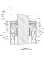
- 1 is a diagram showing an example of a partial cross-section of a shock absorber according to a first embodiment
- 11A and 11B are diagrams illustrating an example of the function of a shock absorber.
- 11A and 11B are diagrams illustrating an example of the function of a shock absorber.
- 11A and 11B are diagrams illustrating an example of the function of a shock absorber.
- 13 is a diagram showing an example of a cross section of a guide member according to a second embodiment.
- FIG. 13 is a diagram showing an example of a cross section of a guide member according to a third embodiment.
- FIG. 13 is a diagram showing an example of a cross section of a guide member according to a fourth embodiment.
- FIG. 13 is a diagram showing an example of a cross section of a guide member according to a fifth embodiment.
- FIG. FIG. 23 is a diagram showing an example of a cross section of a guide member according to a sixth embodiment.
- FIG. 23 is a diagram showing an example of a cross section of a guide member according to the seventh embodiment.
- FIG. 23 is a diagram showing an example of a view of a guide member according to the seventh embodiment as seen from the outside.
- 13 is a diagram showing an example of a cross section of a shock absorber to which an outer cylinder body according to a modified example is applied
- FIG. 1 is a diagram showing an example of a schematic configuration of a suspension device 1 according to the first embodiment.
- 2 is a diagram showing an example of a partial cross section of the shock absorber 2 according to the first embodiment, and is an enlarged view of a portion II-II in FIG.
- the suspension system 1 is a strut-type suspension used in four-wheeled vehicles such as passenger automobiles, and as shown in Fig. 1, comprises a hydraulic shock absorber 2 and a coil spring 3 arranged on the outside of the shock absorber 2.
- the suspension system 1 also comprises a lower spring seat 4 that supports an end of the coil spring 3 on a first axial side (lower side in Fig. 1) of a rod 20 described below, and an upper spring seat 5 that supports an end of the coil spring 3 on a second axial side (upper side in Fig. 1) of the rod 20.
- the suspension 1 also includes a vehicle body bracket 6 that is attached to the second axial end of the rod 20 for mounting the suspension 1 to a vehicle, and a wheel side bracket 7 that is fixed to the first axial end of the rod 20 in the cylinder section 10 (described later) for mounting the suspension 1 to a wheel.
- the suspension 1 also includes a dust cover 8 that covers at least a portion of the cylinder section 10 and the rod 20.
- the axial direction of the rod 20 may be simply referred to as the "axial direction.”
- the axial direction is also the direction of the center line of the cylindrical cylinder 11, which will be described later.
- the first axial side (lower side in FIG. 1) and the second axial side (upper side in FIG. 1) may be simply referred to as the “first side” and the “second side,” respectively.
- the direction that intersects with the axial direction e.g., the perpendicular direction
- the side of the center line of the cylinder 11 may be simply referred to as the "inner side,” and the side away from the center line may be simply referred to as the "outer side.”
- the shock absorber 2 includes a cylinder portion 10 that contains hydraulic oil, and a rod 20 whose second end protrudes from the cylinder portion 10 and whose first end is inserted into the cylinder portion 10.
- the shock absorber 2 also includes a piston portion 30 that is provided at the first end of the rod 20, and a bottom portion 40 that is provided at the first end of the cylinder portion 10.
- the shock absorber 2 also includes a rebound sheet 50 that is fixed to the rod 20, and a rebound rubber 51 that is an annular elastic member that is arranged on the second side of the rebound sheet 50 in order to reduce the impact when the rod 20 extends.
- the cylinder section 10 also includes a rod guide section 60 that movably supports the rod 20, a bump stopper cap 15 attached to the second end of the outer cylinder body 12, and a seal member 80 that prevents hydraulic oil from leaking from within the cylinder section 10 and prevents foreign matter from entering the cylinder section 10.
- the cylinder portion 10 is also provided with a guide member 100 that is disposed in the reservoir chamber R and that guides the hydraulic oil flowing out from a flow passage 75 (described later) formed in the rod guide portion 60 to the outer tube body 12 .
- the rod guide portion 60, the seal member 80 and the guide member 100 will be described in detail later.
- the rod 20 is a rod-shaped member that extends in the axial direction.
- the rod 20 holds the piston portion 30 on the first side.
- the rod 20 also connects to the vehicle body, for example, via the vehicle body bracket 6 on the second side.
- the piston portion 30 includes a piston 31, a valve group 32 that blocks first ends of some of the oil passages formed in the piston 31, and a valve group 33 that blocks second ends of some of the oil passages formed in the piston 31.
- the piston 31 contacts the inner surface of the cylinder 11 via a sealing member provided on its outer surface, and divides the space inside the cylinder 11 containing hydraulic oil into a first oil chamber Y1 on the first side of the piston 31 and a second oil chamber Y2 on the second side of the piston 31.
- the bottom portion 40 includes a valve body 41 having a plurality of oil passages passing through in the axial direction, a valve 42 provided on a first side of the valve body 41, and a valve 43 provided on a second side of the valve body 41.
- the valve body 41 of the bottom portion 40 separates the first oil chamber Y1 and the reservoir chamber R.
- the inner diameter of the guide 61 is set slightly larger than the outer diameter of the rod 20 inserted inside.
- the inner diameter of the guide 61 is 0.1 mm to 1 mm larger than the outer diameter of the rod 20.
- the inner circumferential surface of the guide 61 comes into contact with the outer circumferential surface of the rod 20, so it is molded from a material that is more abrasion resistant than the guide case 70.
- the guide case 70 has a cylindrical inner cylindrical portion 71 provided on the inside, and a cylindrical outer cylindrical portion 72 provided on the outside of the inner cylindrical portion 71.
- the inner cylindrical portion 71 and the outer cylindrical portion 72 are integrally molded so that the outer peripheral surface of the second side portion of the inner cylindrical portion 71 and the inner peripheral surface of the first side portion of the outer cylindrical portion 72 are joined.
- the guide 61 is fitted inside the inner cylindrical portion 71.
- the outer diameter of the inner cylindrical portion 71 is formed to be smaller than the inner diameter of the cylinder 11, and the inner cylindrical portion 71 is disposed inside the cylinder 11.
- the outer cylindrical portion 72 is disposed between the rod 20 and the outer tube body 12 on the second side of the cylinder 11. The outer diameter of the outer cylindrical portion 72 is smaller than the inner diameter of the end of the outer tube body 12 on the second side.
- the outer cylindrical portion 72 has an inner recess 721 formed at the end of the second side on the inside and recessed from the end face of the second side, an outer recess 722 formed at the end of the second side on the outside and recessed from the end face of the second side, and an outer peripheral recess 723 formed from the end of the first side to the center and recessed from the outer peripheral surface.
- the opening of the inner recess 721 on the second side is chamfered.
- the outer recess 722 is recessed in a cylindrical shape, and is formed such that the outer diameter of the second side end of the outer cylindrical portion 72 gradually decreases toward the second side.
- the outer peripheral recess 723 is recessed into a cylindrical shape. However, the outer peripheral recess 723 is formed so that the outer diameter of the first side end of the outer cylindrical portion 72 is larger than the outer diameter of the cylinder 11.
- an inclined surface 724 is formed in the second side portion of the outer peripheral recess 723, so that the outer diameter of the outer cylindrical portion 72 gradually decreases as it approaches the first side.
- the outer cylindrical portion 72 is formed with a flow path 75 that returns hydraulic oil that has passed through the gap between the rod 20 and the guide 61 to the second side of the guide case 70 to the reservoir chamber R.
- the opening on the second side of the flow path 75 can be, for example, located outside a central seal portion 824 (described later) of the seal member 80 in the inner recess 721 and inside the outer recess 722.
- the opening on the first side of the flow path 75 can be, for example, located on the inclined surface 724.
- At least one flow passage 75 is formed in the circumferential direction of the guide case 70.
- the flow passages 75 may be formed, for example, every 90 degrees or every 180 degrees.
- the guide case 70 configured as above can be made of, for example, a metal such as steel or a non-metallic material such as polytetrafluoroethylene.
- the seal member 80 has an annular ring 81 made of a metal such as steel, and an elastic portion 82 made of a material with a low elastic modulus such as synthetic rubber.
- the seal member 80 is formed by, for example, baking and bonding the elastic portion 82 to the ring 81, and the ring 81 holds the elastic portion 82.
- the ring 81 is annular, and has an inner diameter larger than the outer diameter of the rod 20, and an outer diameter smaller than the inner diameter of the second end of the outer cylinder body 12 and equal to or larger than the outer diameter of the outer cylindrical portion 72 of the guide case 70.
- the elastic portion 82 is provided on the first side of the ring 81, has a wedge-shaped cross section, and has a seal lip portion 821 that is pressed by an annular spring to come into close contact with the entire outer periphery of the rod 20.
- the elastic portion 82 is also provided on the second side of the ring 81, and has a dust lip 822 that comes into close contact with the entire outer periphery of the rod 20 to prevent dust from entering from the outside.
- the elastic portion 82 also has an outer circumferential seal portion 823 that protrudes from the outer circumferential portion of the ring 81 all around in a direction inclined axially toward the first side and outward.
- the outer circumferential seal portion 823 is located in the outer recess 722 of the guide case 70 of the rod guide portion 60 and contacts the inner circumferential surface of the outer cylinder body 12, thereby preventing hydraulic oil from leaking from the gap between the outer circumferential surface of the guide case 70 and the inner circumferential surface of the outer cylinder body 12.
- the elastic portion 82 also has a central seal portion 824 that protrudes from the inner periphery of the ring 81 all around in a direction inclined axially outward toward the first side.
- the central seal portion 824 comes into contact with the inner recess 721 of the outer cylindrical portion 72 of the guide case 70, thereby preventing the hydraulic oil and gas filled in the reservoir chamber R from moving inward via the flow path 75.
- the seal member 80 When assembling the shock absorber 2, the seal member 80 is inserted into the outer cylinder 12 after the rod guide portion 60 is inserted into the outer cylinder 12 until the first end face 810 of the ring 81 contacts the second end face of the outer cylindrical portion 72 of the guide case 70. The seal member 80 is then held in place by the outer cylinder 12, with the end portion on the second side of the outer cylinder 12 being bent inward, a process known as roll crimping.
- the guide member 100 has a cylindrical portion 110 disposed between the cylinder 11 and the outer cylinder body 12, and a connection portion 120 that connects the cylindrical portion 110 and the cylinder 11.
- the guide member 100 can be, for example, formed by applying a drawing process to a thin metal plate.
- the cylindrical portion 110 is disposed at a position closer to the outer cylinder 12 than the cylinder 11.
- the gap G1 between the cylindrical portion 110 and the outer cylinder 12 can be 0.5 mm to 1 mm
- the gap G2 between the cylindrical portion 110 and the cylinder 11 can be 2 mm or more.
- the connecting portion 120 has a cylindrical fitting portion 121 that is fitted into the outer peripheral surface of the cylinder 11, and an inclined portion 122 that is inclined toward the second side and outward in the axial direction from the second end of the fitting portion 121.
- the second end of the inclined portion 122 is connected to the first end of the cylindrical portion 110.
- the guide member 100 is held in the cylinder 11 by fitting the fitting portion 121 into the outer peripheral surface of the cylinder 11.
- the fitting portion 121 can be press-fitted into the outer peripheral surface of the cylinder 11.
- the fitting portion 121 may be joined to the outer peripheral surface of the cylinder 11 by, for example, welding or adhesive.
- the guide member 100 configured as described above is disposed at the end of the second side of the cylinder 11 so as not to come into contact with the hydraulic oil (hereinafter sometimes referred to as "reserved oil Os") on the first side in the reservoir chamber R.
- the guide member 100 is disposed at a position where the hydraulic oil in the reservoir chamber R does not come into contact with the guide member 100.
- the shock absorber 2 includes the cylinder 11, the outer cylinder body 12 that is disposed outside the cylinder 11 and covers the cylinder 11, and the piston portion 30 that divides the hydraulic oil chambers (e.g., the first oil chamber Y1 and the second oil chamber Y2) formed in the cylinder 11.
- the shock absorber 2 also includes a reservoir chamber R that is formed between the cylinder 11 and the outer cylinder body 12 and is filled with hydraulic oil on the bottom side (e.g., the first side, the bottom cover 13 side) and with gas on the opening side (e.g., the second side) of the cylinder 11.
- the shock absorber 2 also includes a rod guide portion 60 as an example of a support member that is disposed at the opening of the cylinder 11 and slidably supports the rod 20 that holds the piston portion 30 at one end side (e.g., the first side), and has a flow path 75 formed therein that returns the hydraulic oil that has passed through a gap with the rod 20 to the opening side (e.g., the second side) to the reservoir chamber R.
- the shock absorber 2 is also provided with a guide member 100 that is disposed in the reservoir chamber R and that comes into contact with the outflow oil Of (see FIG. 3), which is hydraulic oil that has flowed out of the flow passage 75, more than with the stored oil Os, which is an example of hydraulic oil, in the reservoir chamber R, and guides the outflow oil Of to the outer cylinder body 12.
- FIG. 3 is a diagram showing an example of the operation of the shock absorber 2.
- FIG. 4 is a diagram showing an example of the operation of the shock absorber 2.
- the outflow oil Of which is the hydraulic oil flowing out from the flow path 75
- the space S1 formed between the inside of the cylindrical portion 110 and the connection portion 120 of the guide member 100 and the outer peripheral surface of the cylinder 11.
- the outflow oil Of overflowing from the space S1 passes between the cylindrical portion 110 of the guide member 100 and the outer cylinder body 12 and falls to the first side.
- the outflow oil Of overflowing from the space S1 falls while contacting the inner peripheral surface of the outer cylinder body 12. Since the outer peripheral surface of the outer cylinder body 12 is in contact with the outside air, the outflow oil Of is cooled by contacting the outer cylinder body 12. Then, the cooled outflow oil Of mixes with the hydraulic oil in the reservoir chamber R, and the temperature of the hydraulic oil in the cylinder portion 10 is reduced. As a result, the temperature of the hydraulic oil in the cylinder portion 10 can be prevented from becoming too high and from exceeding a predetermined temperature.
- the predetermined temperature is determined taking into consideration the life of the hydraulic oil and the temperature at which deterioration of the elastic portion 82 of the seal member 80 progresses.
- FIG. 5 is a diagram showing an example of the operation of the shock absorber 2.
- the suspension 1 may be mounted on the four-wheeled vehicle in a state in which it is inclined with respect to a direction perpendicular to the horizontal plane (inclined at an inclination angle ⁇ (e.g., 30 degrees)).
- the shock absorber 2 can store the hydraulic oil flowing out of the flow path 75 in the space S1 with a high degree of certainty, and can also bring the hydraulic oil overflowing from the space S1 into contact with the outer cylinder body 12 with a high degree of certainty.
- FIG. 6 is a diagram showing an example of a cross section of a guide member 200 according to the second embodiment.
- the guide member 200 according to the second embodiment is different from the guide member 100 according to the first embodiment in that it has a cylindrical portion 210 corresponding to the cylindrical portion 110.
- the differences from the first embodiment will be described below.
- the same reference numerals are used for the same parts in the first and second embodiments, and detailed descriptions thereof will be omitted.
- the cylindrical portion 210 has a cylindrical main body 211 and a protruding portion 212 that protrudes from the inside to the outside over the entire circumference and is provided at the end portion on the second side of the main body 211.
- a gap G3 between the outer end portion of the protruding portion 212 and the outer cylinder body 12 is, for example, 0.5 mm to 1 mm, and a gap G4 between the main body 211 and the cylinder 11 is, for example, 1 mm or more.
- the protruding portion 212 may be formed so as to be perpendicular to the axial direction, or may be formed in an arc shape with the second side being convex.
- the hydraulic oil flowing out from the flow path 75 (in other words, the outflow oil Of (see, for example, FIG. 3)) falls onto the protruding portion 212 of the guide member 200, and then a portion of it moves outward on the protruding portion 212 and falls between the protruding portion 212 and the outer cylinder body 12. Also, a portion of the hydraulic oil that flows out from the flow path 75 and falls onto the protruding portion 212 of the guide member 200 moves inward on the protruding portion 212 and accumulates in the space S2 formed between the inside of the cylindrical portion 210 and the connecting portion 120 of the guide member 200 and the outer peripheral surface of the cylinder 11.
- the hydraulic oil that overflows from the space S2 falls between the protruding portion 212 of the guide member 200 and the outer cylinder body 12. Because the gap G3 between the protruding portion 212 and the outer cylinder body 12 is narrow, the hydraulic oil that overflows from the space S2 tends to fall while contacting the inner peripheral surface of the outer cylinder body 12. And because the outer circumferential surface of the external cylinder 12 is exposed to the outside air, the hydraulic oil is cooled by contacting the external cylinder 12. Therefore, by providing the guide member 200, it is possible to prevent the temperature of the hydraulic oil in the cylinder portion 10 from becoming too high.
- FIG. 7 is a diagram showing an example of a cross section of a guide member 300 according to the third embodiment.
- the guide member 300 according to the third embodiment differs from the guide member 100 according to the first embodiment in that it does not include a space S1 for storing hydraulic oil flowing out from the flow path 75.
- the differences from the first embodiment will be described below.
- the same reference numerals are used for the same parts in the first and third embodiments, and detailed descriptions thereof will be omitted.
- the guide member 300 has a cylindrical fitting portion 310 that is fitted into the outer peripheral surface of the cylinder 11, and a protrusion 320 that protrudes from a first end of the fitting portion 310 toward the first side and outward in a direction inclined relative to the axial direction around the entire circumference.
- the gap G5 between the outer end of the protrusion 320 and the outer cylinder body 12 can be, for example, 0.5 mm to 1 mm.
- the hydraulic oil flowing out from the flow path 75 (in other words, the outflow oil Of (see, for example, FIG. 3)) falls onto the protruding portion 320 of the guide member 300, moves on the protruding portion 320 to the first side and outside, and falls through the gap between the protruding portion 320 and the external cylinder 12.
- the guide member 300 guides more of the hydraulic oil flowing out from the flow path 75 to the external cylinder 12 than to the cylinder 11.
- the hydraulic oil that falls through the gap between the protruding portion 320 and the external cylinder 12 tends to fall while contacting the inner circumferential surface of the external cylinder 12.
- the hydraulic oil is cooled by contacting the external cylinder 12. Therefore, by providing the guide member 300, it is possible to prevent the temperature of the hydraulic oil in the cylinder portion 10 from becoming too high.
- the outer end of the protruding portion 320 of the guide member 300 may have a plurality of notches recessed inward from the outer periphery in the circumferential direction. This makes it possible to prevent the temperature of the hydraulic oil in the cylinder portion 10 from becoming too low due to an increase in the amount of outflow oil Of contacting the inner periphery of the outer cylinder body 12.
- FIG. 8 is a diagram showing an example of a cross section of a guide member 400 according to the fourth embodiment.
- the guide member 400 according to the fourth embodiment differs from the guide member 100 according to the first embodiment in that it does not include a space S1 for storing hydraulic oil flowing out from the flow path 75.
- the differences from the first embodiment will be described below.
- the same reference numerals are used for the same parts in the first and fourth embodiments, and detailed descriptions thereof will be omitted.
- the guide member 400 has a cylindrical fitting portion 410 that is fitted into the outer circumferential surface of the cylinder 11, and a protruding portion 420 that protrudes outward over the entire circumference from the second side end of the fitting portion 410.
- the protruding portion 420 may be formed so as to be perpendicular to the axial direction, or may be formed so as to be inclined toward the first side and outward in the axial direction.
- the gap G6 between the outer end of the protrusion 420 and the outer cylinder body 12 can be, for example, 0.5 mm to 1 mm.
- the hydraulic oil flowing out of the flow path 75 falls onto the protruding portion 420 of the guide member 400, then moves outward on the protruding portion 420 and falls between the protruding portion 420 and the outer cylinder body 12. Because the gap G6 between the protruding portion 420 and the outer cylinder body 12 is narrow, the hydraulic oil that falls between the protruding portion 420 and the outer cylinder body 12 tends to fall while contacting the inner circumferential surface of the outer cylinder body 12. And because the outer circumferential surface of the outer cylinder body 12 is exposed to the outside air, the hydraulic oil is cooled by contacting the outer cylinder body 12. Therefore, by providing the guide member 400, it is possible to prevent the temperature of the hydraulic oil from becoming too high.
- the guide member 400 is molded separately from the cylinder 11, and then is fitted or joined to the cylinder 11 to be integrated with the cylinder 11.
- this is not particularly limited to this form.
- the guide member 400 and the cylinder 11 may be molded as a single unit.
- the fitting portion 410 is not necessarily required, and only the protruding portion 420 may be provided. In other words, the protruding portion 420 may protrude outward from the second end of the cylinder 11.
- FIG. 9 is a diagram showing an example of a cross section of a guide member 500 according to the fifth embodiment.
- the guide member 500 according to the fifth embodiment differs from the guide member 400 according to the fourth embodiment in that the guide member 500 is integrated with the guide case 70 of the rod guide portion 60.
- the differences from the fourth embodiment will be described below.
- the same reference numerals are used for the same parts in the fourth and fifth embodiments, and detailed descriptions thereof will be omitted.
- the guide member 500 has a cylindrical fitting portion 510 that is fitted into a first end of the outer cylindrical portion 72 of the guide case 70, and a protruding portion 520 that protrudes outward over the entire circumference from a second end of the fitting portion 510.
- the protruding portion 520 may be formed so as to be perpendicular to the axial direction, or may be formed so as to be inclined toward the first side and outward with respect to the axial direction.
- the gap G7 between the outer end of the protrusion 520 and the outer cylinder body 12 can be, for example, 0.5 mm to 1 mm.
- the guide member 500 is held in the guide case 70 by fitting the fitting portion 510 into the outer peripheral surface of the outer cylindrical portion 72 of the guide case 70.
- the fitting portion 510 can be press-fitted into the outer peripheral surface of the guide case 70.
- the fitting portion 510 can be joined to the outer peripheral surface of the guide case 70 by, for example, welding or adhesive.
- the hydraulic oil flowing out of the flow path 75 falls onto the protruding portion 520 of the guide member 500, then moves outward on the protruding portion 520 and falls between the protruding portion 520 and the outer cylinder body 12. Because the gap G7 between the protruding portion 520 and the outer cylinder body 12 is narrow, the hydraulic oil that falls between the protruding portion 520 and the outer cylinder body 12 tends to fall while contacting the inner peripheral surface of the outer cylinder body 12. And because the outer peripheral surface of the outer cylinder body 12 is exposed to the outside air, the hydraulic oil is cooled by contacting the outer cylinder body 12. Therefore, by providing the guide member 500, it is possible to prevent the temperature of the hydraulic oil from becoming too high.
- the guide member 500 is molded separately from the guide case 70, and then is fitted or joined to the guide case 70 to be integrated with the guide case 70.
- this is not particularly limited to this form.
- the guide member 500 and the guide case 70 may be molded integrally.
- the fitting portion 510 is not necessarily required, and only the protrusion portion 520 may be provided.
- guide member 500 according to the fifth embodiment may be provided together with the guide member 400 according to the fourth embodiment.
- FIG. 10 is a diagram showing an example of a cross section of a guide member 600 according to the sixth embodiment.
- the guide member 600 according to the sixth embodiment differs from the guide member 400 according to the fourth embodiment in that it is not integrated with the cylinder 11, but is sandwiched between the cylinder 11 and the guide case 70 of the rod guide portion 60.
- the differences from the fourth embodiment will be described below.
- the same reference numerals are used for the same parts in the fourth and sixth embodiments, and detailed descriptions thereof will be omitted.
- the guide member 600 is a circular ring-shaped member formed from a thin plate.
- the guide member 600 may be formed so as to be perpendicular to the axial direction, or so that the outer portion is inclined toward the first side and outward with respect to the axial direction.
- the guide member 600 is held by being sandwiched between the second end of the cylinder 11 and the first end of the guide case 70 .
- the gap G8 between the outer end of the guide member 600 and the outer cylinder body 12 can be, for example, 0.5 mm to 1 mm.
- the hydraulic oil flowing out of the flow path 75 falls onto the guide member 600, then moves outward on the guide member 600 and falls between the guide member 600 and the outer cylinder body 12. Because the gap G8 between the guide member 600 and the outer cylinder body 12 is narrow, the hydraulic oil that falls between the guide member 600 and the outer cylinder body 12 tends to fall while contacting the inner circumferential surface of the outer cylinder body 12. And because the outer circumferential surface of the outer cylinder body 12 is exposed to the outside air, the hydraulic oil is cooled by contacting the outer cylinder body 12. Therefore, by providing the guide member 600, it is possible to prevent the temperature of the hydraulic oil from becoming too high.
- FIG. 11 is a diagram showing an example of a cross section of a guide member 700 according to the seventh embodiment.
- FIG. 12 is a diagram showing an example of a perspective view of a guide member 700 according to the seventh embodiment as viewed from the second side.
- the guide member 700 according to the seventh embodiment differs from the guide member 400 according to the fourth embodiment in that the protrusion 720 corresponding to the protrusion 420 is not formed over the entire circumference, but is formed in a plurality of parts in the circumferential and axial directions.
- the differences from the fourth embodiment will be described below.
- the same reference numerals are used for the same parts in the fourth and seventh embodiments, and detailed description thereof will be omitted.
- the guide member 700 has a fitting portion 710 that fits into the outer peripheral surface of the cylinder 11, and a protruding portion 720 that protrudes outward from the outer peripheral surface of the fitting portion 710.
- the protruding portion 720 can be exemplified as a rectangular shape formed perpendicular to the axial direction.
- a plurality of protruding portions 720 are provided in the circumferential direction and the axial direction. In the example shown in FIG. 12, eight protruding portions 720 are formed in the circumferential direction (every 45 degrees) and four stages are formed in the axial direction, and the circumferential phase of the eight protruding portions 720 provided in adjacent stages is shifted by 22.5 degrees.
- the protruding portion 720 of the stage provided on the first side of both ends in the circumferential direction of one protruding portion 720 is arranged.
- the protruding portion 720 can be exemplified as being formed, for example, over approximately 30 degrees in the circumferential direction.
- the hydraulic oil flowing out from the flow path 75 falls onto the protrusion 720, and then a portion of the hydraulic oil moves circumferentially over the protrusion 720 and falls onto the protrusion 720 of the step provided on the first side of the step on which the protrusion 720 on which the hydraulic oil flowed out of the flow path 75 fell is provided. Thereafter, a portion of the hydraulic oil that fell onto the protrusion 720 falls onto the protrusion 720 of the step provided on the first side of the step on which the protrusion 720 is provided.
- the hydraulic oil flowing out from the flow path 75 falls while moving circumferentially from the protrusion 720 of the step provided on the second side to the protrusion 720 of the step provided on the first side.
- the speed at which the hydraulic oil flowing out of the flow path 75 reaches the hydraulic oil stored on the first side of the reservoir chamber R is slower when it moves over the multiple protrusions 720 than when it falls between the protrusions 720 and the external cylinder body 12.
- the hydraulic oil flowing out of the flow path 75 falls slowly while moving over the multiple protrusions 720.
- the hydraulic oil falling while moving over the multiple protrusions 720 is cooled more than the hydraulic oil falling between the protrusions 720 and the external cylinder body 12. Therefore, the guide member 700 can reliably prevent the temperature of the hydraulic oil from becoming too high.
- FIG. 13 is a diagram showing an example of a cross section of a shock absorber 2 to which an outer cylinder body 912 according to a modified example is applied.
- the outer cylinder 912 according to the modified example has an inner protrusion 913 at the end on the second side, which protrudes inward from the inner circumferential surface all around.
- the inner protrusion 913 is provided at a location where the hydraulic oil flowing out from the flow passage 75 (in other words, the outflow oil Of (see Fig. 3, for example)) comes into contact with the hydraulic oil stored in the reservoir chamber R before mixing with it.
- the inner protrusion 913 can be formed, for example, by performing bulge processing on a cylindrical member, but may be formed by other methods.
- the outer cylinder body 912 according to the modified example can be applied to any of the guide members from the guide member 100 according to the first embodiment to the guide member 700 according to the seventh embodiment.
- 1...Suspension device 2...Shock absorber, 3...Coil spring (an example of a spring), 10...Cylinder section, 11...Cylinder, 12...Outer cylinder body, 20...Rod, 30...Piston section, 100, 200, 300, 400, 500, 600, 700...Guide member, 60...Rod guide section (an example of a support member), 75...Flow path, 80...Sealing member, 110...Cylindrical section, 120...Connection section, 212, 320, 420, 520, 720...Protrusion, Of...Outflowing oil, Os...Stored oil, R...Reservoir chamber, S1...Space
Landscapes
- Engineering & Computer Science (AREA)
- General Engineering & Computer Science (AREA)
- Mechanical Engineering (AREA)
- Fluid-Damping Devices (AREA)
Priority Applications (4)
| Application Number | Priority Date | Filing Date | Title |
|---|---|---|---|
| JP2024571575A JPWO2024154337A1 (https=) | 2023-01-20 | 2023-01-20 | |
| DE112023004663.8T DE112023004663T5 (de) | 2023-01-20 | 2023-01-20 | Stossdämpfende vorrichtung und aufhängungsvorrichtung |
| CN202380091140.1A CN120513355A (zh) | 2023-01-20 | 2023-01-20 | 缓冲装置和悬架装置 |
| PCT/JP2023/001719 WO2024154337A1 (ja) | 2023-01-20 | 2023-01-20 | 緩衝装置、懸架装置 |
Applications Claiming Priority (1)
| Application Number | Priority Date | Filing Date | Title |
|---|---|---|---|
| PCT/JP2023/001719 WO2024154337A1 (ja) | 2023-01-20 | 2023-01-20 | 緩衝装置、懸架装置 |
Publications (1)
| Publication Number | Publication Date |
|---|---|
| WO2024154337A1 true WO2024154337A1 (ja) | 2024-07-25 |
Family
ID=91955681
Family Applications (1)
| Application Number | Title | Priority Date | Filing Date |
|---|---|---|---|
| PCT/JP2023/001719 Ceased WO2024154337A1 (ja) | 2023-01-20 | 2023-01-20 | 緩衝装置、懸架装置 |
Country Status (4)
| Country | Link |
|---|---|
| JP (1) | JPWO2024154337A1 (https=) |
| CN (1) | CN120513355A (https=) |
| DE (1) | DE112023004663T5 (https=) |
| WO (1) | WO2024154337A1 (https=) |
Citations (5)
| Publication number | Priority date | Publication date | Assignee | Title |
|---|---|---|---|---|
| JPS53139493U (https=) * | 1977-04-11 | 1978-11-04 | ||
| JPH0248635U (https=) * | 1988-09-30 | 1990-04-04 | ||
| US4955460A (en) * | 1988-08-01 | 1990-09-11 | Monroe Auto Equipment Company | Control valve for shock absorbers |
| JP2005188601A (ja) * | 2003-12-25 | 2005-07-14 | Hitachi Ltd | 油圧緩衝器 |
| JP6080257B2 (ja) * | 2013-01-25 | 2017-02-15 | Kyb株式会社 | 緩衝器 |
-
2023
- 2023-01-20 JP JP2024571575A patent/JPWO2024154337A1/ja active Pending
- 2023-01-20 WO PCT/JP2023/001719 patent/WO2024154337A1/ja not_active Ceased
- 2023-01-20 CN CN202380091140.1A patent/CN120513355A/zh active Pending
- 2023-01-20 DE DE112023004663.8T patent/DE112023004663T5/de active Pending
Patent Citations (5)
| Publication number | Priority date | Publication date | Assignee | Title |
|---|---|---|---|---|
| JPS53139493U (https=) * | 1977-04-11 | 1978-11-04 | ||
| US4955460A (en) * | 1988-08-01 | 1990-09-11 | Monroe Auto Equipment Company | Control valve for shock absorbers |
| JPH0248635U (https=) * | 1988-09-30 | 1990-04-04 | ||
| JP2005188601A (ja) * | 2003-12-25 | 2005-07-14 | Hitachi Ltd | 油圧緩衝器 |
| JP6080257B2 (ja) * | 2013-01-25 | 2017-02-15 | Kyb株式会社 | 緩衝器 |
Also Published As
| Publication number | Publication date |
|---|---|
| JPWO2024154337A1 (https=) | 2024-07-25 |
| CN120513355A (zh) | 2025-08-19 |
| DE112023004663T5 (de) | 2025-08-28 |
Similar Documents
| Publication | Publication Date | Title |
|---|---|---|
| US7810619B2 (en) | Fluid-pressure shock absorber | |
| US10816055B2 (en) | Damper bumper cap with labyrinth air passageway | |
| US11173764B2 (en) | Air suspension strut having a sealed closure cap | |
| AU2003204306A1 (en) | Dust cover receiving structure of shock absorber | |
| JP7202139B2 (ja) | 緩衝器および緩衝器の設置構造 | |
| WO2024154337A1 (ja) | 緩衝装置、懸架装置 | |
| US12558934B2 (en) | Damper oil seal cap with seal protection feature | |
| JP6838238B2 (ja) | 緩衝器 | |
| US12018732B2 (en) | Hydraulic damper | |
| EP3379102B1 (en) | Bump stopper and buffer | |
| WO2024201696A1 (ja) | 緩衝装置、懸架装置 | |
| JP2025163713A (ja) | 緩衝器 | |
| JP2023151003A (ja) | シリンダ装置、懸架装置 | |
| JP2024155262A (ja) | リバウンドスプリングユニット、懸架装置 | |
| KR102725402B1 (ko) | 완충기 | |
| JP2024051645A (ja) | 懸架装置 | |
| JP2025140816A (ja) | バンプストッパ、緩衝器 | |
| US20250121640A1 (en) | Damper bumper cap with collector | |
| JP2026053068A (ja) | 緩衝装置 | |
| WO2024228248A1 (ja) | 緩衝装置、懸架装置 | |
| JP2024154296A (ja) | キャップ、緩衝装置 | |
| JP7588154B2 (ja) | 密封装置 | |
| JP2007113624A (ja) | 油圧緩衝器 | |
| JP2025082108A (ja) | 筒状部材、緩衝装置 | |
| JP7198053B2 (ja) | 緩衝器 |
Legal Events
| Date | Code | Title | Description |
|---|---|---|---|
| 121 | Ep: the epo has been informed by wipo that ep was designated in this application |
Ref document number: 23917550 Country of ref document: EP Kind code of ref document: A1 |
|
| WWE | Wipo information: entry into national phase |
Ref document number: 112023004663 Country of ref document: DE |
|
| ENP | Entry into the national phase |
Ref document number: 2024571575 Country of ref document: JP Kind code of ref document: A |
|
| WWE | Wipo information: entry into national phase |
Ref document number: 2024571575 Country of ref document: JP |
|
| WWE | Wipo information: entry into national phase |
Ref document number: 202380091140.1 Country of ref document: CN |
|
| WWP | Wipo information: published in national office |
Ref document number: 202380091140.1 Country of ref document: CN |
|
| WWP | Wipo information: published in national office |
Ref document number: 112023004663 Country of ref document: DE |
|
| 122 | Ep: pct application non-entry in european phase |
Ref document number: 23917550 Country of ref document: EP Kind code of ref document: A1 |