US10816055B2 - Damper bumper cap with labyrinth air passageway - Google Patents
Damper bumper cap with labyrinth air passageway Download PDFInfo
- Publication number
- US10816055B2 US10816055B2 US15/964,317 US201815964317A US10816055B2 US 10816055 B2 US10816055 B2 US 10816055B2 US 201815964317 A US201815964317 A US 201815964317A US 10816055 B2 US10816055 B2 US 10816055B2
- Authority
- US
- United States
- Prior art keywords
- piston rod
- cap
- side wall
- wall
- damper tube
- Prior art date
- Legal status (The legal status is an assumption and is not a legal conclusion. Google has not performed a legal analysis and makes no representation as to the accuracy of the status listed.)
- Active
Links
- 239000000428 dust Substances 0.000 claims abstract description 67
- 239000012530 fluid Substances 0.000 claims description 9
- 238000004891 communication Methods 0.000 claims description 3
- 238000007789 sealing Methods 0.000 claims description 2
- 239000006096 absorbing agent Substances 0.000 description 39
- 230000035939 shock Effects 0.000 description 39
- 239000000725 suspension Substances 0.000 description 13
- 239000000356 contaminant Substances 0.000 description 12
- XLYOFNOQVPJJNP-UHFFFAOYSA-N water Substances O XLYOFNOQVPJJNP-UHFFFAOYSA-N 0.000 description 6
- 230000006835 compression Effects 0.000 description 5
- 238000007906 compression Methods 0.000 description 5
- -1 without limitation Substances 0.000 description 5
- 239000000463 material Substances 0.000 description 4
- 238000000034 method Methods 0.000 description 4
- 238000013022 venting Methods 0.000 description 3
- 239000004952 Polyamide Substances 0.000 description 2
- 239000013536 elastomeric material Substances 0.000 description 2
- 229920002647 polyamide Polymers 0.000 description 2
- 230000000717 retained effect Effects 0.000 description 2
- 229920000742 Cotton Polymers 0.000 description 1
- 239000004743 Polypropylene Substances 0.000 description 1
- 230000000712 assembly Effects 0.000 description 1
- 238000000429 assembly Methods 0.000 description 1
- 238000011109 contamination Methods 0.000 description 1
- 230000007423 decrease Effects 0.000 description 1
- 238000005516 engineering process Methods 0.000 description 1
- 238000001746 injection moulding Methods 0.000 description 1
- 238000009434 installation Methods 0.000 description 1
- 230000000670 limiting effect Effects 0.000 description 1
- 238000004519 manufacturing process Methods 0.000 description 1
- 238000012986 modification Methods 0.000 description 1
- 230000004048 modification Effects 0.000 description 1
- 230000036961 partial effect Effects 0.000 description 1
- 239000002245 particle Substances 0.000 description 1
- 238000005192 partition Methods 0.000 description 1
- 229920001155 polypropylene Polymers 0.000 description 1
- 230000002829 reductive effect Effects 0.000 description 1
- 230000002441 reversible effect Effects 0.000 description 1
- 239000000243 solution Substances 0.000 description 1
- 238000012360 testing method Methods 0.000 description 1
Images


Classifications
-
- F—MECHANICAL ENGINEERING; LIGHTING; HEATING; WEAPONS; BLASTING
- F16—ENGINEERING ELEMENTS AND UNITS; GENERAL MEASURES FOR PRODUCING AND MAINTAINING EFFECTIVE FUNCTIONING OF MACHINES OR INSTALLATIONS; THERMAL INSULATION IN GENERAL
- F16F—SPRINGS; SHOCK-ABSORBERS; MEANS FOR DAMPING VIBRATION
- F16F9/00—Springs, vibration-dampers, shock-absorbers, or similarly-constructed movement-dampers using a fluid or the equivalent as damping medium
- F16F9/32—Details
- F16F9/3207—Constructional features
- F16F9/3235—Constructional features of cylinders
- F16F9/3242—Constructional features of cylinders of cylinder ends, e.g. caps
-
- F—MECHANICAL ENGINEERING; LIGHTING; HEATING; WEAPONS; BLASTING
- F16—ENGINEERING ELEMENTS AND UNITS; GENERAL MEASURES FOR PRODUCING AND MAINTAINING EFFECTIVE FUNCTIONING OF MACHINES OR INSTALLATIONS; THERMAL INSULATION IN GENERAL
- F16F—SPRINGS; SHOCK-ABSORBERS; MEANS FOR DAMPING VIBRATION
- F16F9/00—Springs, vibration-dampers, shock-absorbers, or similarly-constructed movement-dampers using a fluid or the equivalent as damping medium
- F16F9/32—Details
- F16F9/38—Covers for protection or appearance
-
- F—MECHANICAL ENGINEERING; LIGHTING; HEATING; WEAPONS; BLASTING
- F16—ENGINEERING ELEMENTS AND UNITS; GENERAL MEASURES FOR PRODUCING AND MAINTAINING EFFECTIVE FUNCTIONING OF MACHINES OR INSTALLATIONS; THERMAL INSULATION IN GENERAL
- F16F—SPRINGS; SHOCK-ABSORBERS; MEANS FOR DAMPING VIBRATION
- F16F9/00—Springs, vibration-dampers, shock-absorbers, or similarly-constructed movement-dampers using a fluid or the equivalent as damping medium
- F16F9/32—Details
- F16F9/36—Special sealings, including sealings or guides for piston-rods
-
- B—PERFORMING OPERATIONS; TRANSPORTING
- B60—VEHICLES IN GENERAL
- B60G—VEHICLE SUSPENSION ARRANGEMENTS
- B60G13/00—Resilient suspensions characterised by arrangement, location or type of vibration dampers
- B60G13/001—Arrangements for attachment of dampers
-
- B—PERFORMING OPERATIONS; TRANSPORTING
- B60—VEHICLES IN GENERAL
- B60G—VEHICLE SUSPENSION ARRANGEMENTS
- B60G2204/00—Indexing codes related to suspensions per se or to auxiliary parts
- B60G2204/40—Auxiliary suspension parts; Adjustment of suspensions
- B60G2204/41—Elastic mounts, e.g. bushings
-
- B—PERFORMING OPERATIONS; TRANSPORTING
- B60—VEHICLES IN GENERAL
- B60G—VEHICLE SUSPENSION ARRANGEMENTS
- B60G2206/00—Indexing codes related to the manufacturing of suspensions: constructional features, the materials used, procedures or tools
- B60G2206/01—Constructional features of suspension elements, e.g. arms, dampers, springs
- B60G2206/40—Constructional features of dampers and/or springs
- B60G2206/41—Dampers
-
- B—PERFORMING OPERATIONS; TRANSPORTING
- B60—VEHICLES IN GENERAL
- B60G—VEHICLE SUSPENSION ARRANGEMENTS
- B60G2600/00—Indexing codes relating to particular elements, systems or processes used on suspension systems or suspension control systems
- B60G2600/68—Filtering means, e.g. fluid filters
-
- F—MECHANICAL ENGINEERING; LIGHTING; HEATING; WEAPONS; BLASTING
- F16—ENGINEERING ELEMENTS AND UNITS; GENERAL MEASURES FOR PRODUCING AND MAINTAINING EFFECTIVE FUNCTIONING OF MACHINES OR INSTALLATIONS; THERMAL INSULATION IN GENERAL
- F16F—SPRINGS; SHOCK-ABSORBERS; MEANS FOR DAMPING VIBRATION
- F16F2230/00—Purpose; Design features
- F16F2230/0023—Purpose; Design features protective
-
- F—MECHANICAL ENGINEERING; LIGHTING; HEATING; WEAPONS; BLASTING
- F16—ENGINEERING ELEMENTS AND UNITS; GENERAL MEASURES FOR PRODUCING AND MAINTAINING EFFECTIVE FUNCTIONING OF MACHINES OR INSTALLATIONS; THERMAL INSULATION IN GENERAL
- F16F—SPRINGS; SHOCK-ABSORBERS; MEANS FOR DAMPING VIBRATION
- F16F2230/00—Purpose; Design features
- F16F2230/10—Enclosure elements, e.g. for protection
- F16F2230/105—Flexible, e.g. bellows or bladder
-
- F—MECHANICAL ENGINEERING; LIGHTING; HEATING; WEAPONS; BLASTING
- F16—ENGINEERING ELEMENTS AND UNITS; GENERAL MEASURES FOR PRODUCING AND MAINTAINING EFFECTIVE FUNCTIONING OF MACHINES OR INSTALLATIONS; THERMAL INSULATION IN GENERAL
- F16F—SPRINGS; SHOCK-ABSORBERS; MEANS FOR DAMPING VIBRATION
- F16F2230/00—Purpose; Design features
- F16F2230/30—Sealing arrangements
Definitions
- the present disclosure relates to automotive shock absorbers/dampers. More particularly, the present disclosure relates to damper bumper caps that protect the piston rod seal from contact with the jounce bumper of a shock absorber/damper.
- Shock absorbers are typically used in conjunction with automotive suspension systems or other suspension systems to absorb unwanted vibrations that occur during movement of the suspension system. In order to absorb these unwanted vibrations, automotive shock absorbers are generally connected between the sprung (body) and the unsprung (suspension/drivetrain) masses of the vehicle.
- a piston In typical shock absorbers, a piston is located within a fluid chamber defined by a damper tube and is connected to the sprung mass of the vehicle through a piston rod.
- the damper tube is connected to the unsprung mass of the vehicle.
- a seal For the shock absorber to work properly, a seal must be maintained between the piston rod and the damper tube.
- dust particles and other contaminants can accumulate on the piston rod and the piston rod seal, which can cause damage to the piston rod and/or the piston rod seal. Such damage can result in oil leakage from the fluid chamber, which decreases shock absorber function.
- dust covers are commonly used. Dust covers extend annularly about the portion of the piston rod that extends outside the damper tube.
- the dust cover During a compression stroke of the shock absorber, the dust cover is longitudinally compressed. As a result, air is forced out of the inner chamber inside the dust cover. During a rebound stroke of the shock absorber, the dust cover expands longitudinally and air flows into the inner chamber inside the dust cover. The inner chamber inside the dust cover therefore must be vented to the atmosphere. If this were not so, the pressure in the inner chamber inside the dust cover would blow the dust cover off the shock absorber during a compression stroke.
- One problem with venting the inner chamber inside the dust cover is that dust and other contaminants can enter the inner chamber inside the dust cover and foul the piston rod seal. Accordingly, there remains a need for improved venting solutions for dust covers that reduce the amount of dust that enters the inner chamber inside the dust cover.
- a damper system for a vehicle includes a damper tube, a piston rod, and a piston assembly.
- the damper tube extends longitudinally between a rod side end and a closed end.
- the piston rod extends along a longitudinal axis between first and second piston rod ends.
- the first piston rod end supports a jounce bumper and the second piston rod end is disposed inside the damper tube and is coupled to the piston assembly.
- the piston assembly is slidably received in the damper tube and is moveable along the longitudinal axis.
- a piston rod seal is positioned radially between the piston rod and the rod side end of the damper tube.
- a dust cover extends annularly about the rod side end of the damper tube and an exposed portion of the piston rod that is positioned outside the damper tube.
- a damper bumper cap is positioned over the rod side end of the damper tube and the piston rod seal.
- the cap and the dust cover cooperate to define an inner chamber around at least part of the piston rod.
- the cap includes a side wall, an end wall, and an annular skirt.
- the side wall is positioned in contact with the rod side end of the damper tube.
- the side wall extends annularly about the rod side end of the damper tube and longitudinally from the end wall to a side wall end.
- the end wall extends radially inwardly from the side wall and over at least a portion of the piston rod seal.
- the end wall includes a rod aperture through which the piston rod extends.
- the annular skirt is spaced radially outward of the side wall relative to the longitudinal axis.
- connection wall extends between the side wall and the annular skirt.
- the connection wall includes vent openings that define a plurality of tortuous airflow paths through the cap at circumferentially spaced locations that vent the inner chamber to a space outside of the dust cover (e.g., the atmosphere).
- connection wall includes a first group of connection wall segments that extend radially between the side wall and the annular skirt and a second group of connection wall segments that extend radially between the side wall and the annular skirt.
- the connection wall segments in the first group of connection wall segments are arranged at a different height than the connection wall segments in the second group of connection wall segments relative to the side wall end.
- the vent openings and therefore the plurality of tortuous airflow paths are created by the spaces between the connection wall segments in the first group of connection wall segments and the connection wall segments in the second group of connection wall segments.
- FIG. 1 is an illustration of an exemplary vehicle equipped with four shock absorbers constructed in accordance with the teachings of the present disclosure
- FIG. 2 is a side section view of a shock absorber constructed in accordance with the teachings of the present disclosure
- FIG. 3 is a side section view depicting an exemplary damper bumper cap constructed in accordance with the teachings of the present disclosure
- FIG. 4 is a side cross-sectional view depicting the damper bumper cap shown in FIG. 3 after installation in a shock absorber;
- FIG. 5 is a top perspective view depicting the damper bumper cap shown in FIG. 3 ;
- FIG. 6 is a bottom perspective view depicting the damper bumper cap shown in FIG. 3 ;
- FIG. 7 is a bottom perspective view of another exemplary damper bumper cap constructed in accordance with the teachings of the present disclosure where restriction walls have been added;
- FIG. 8 is another bottom perspective view depicting the damper bumper cap shown in FIG. 7 ;
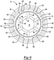
- FIG. 9 is a bottom plan view depicting the damper bumper cap shown in FIG. 7 after a dust cover is installed;
- FIG. 10 is an enlarged, partial bottom perspective view of another exemplary damper bumper cap constructed in accordance with the teachings of the present disclosure where additional restriction walls have been added;
- FIG. 11 is a bottom perspective view of another exemplary damper bumper cap constructed in accordance with the teachings of the present disclosure where filter elements have been added.
- Example embodiments are provided so that this disclosure will be thorough, and will fully convey the scope to those who are skilled in the art. Numerous specific details are set forth such as examples of specific components, devices, and methods, to provide a thorough understanding of embodiments of the present disclosure. It will be apparent to those skilled in the art that specific details need not be employed, that example embodiments may be embodied in many different forms and that neither should be construed to limit the scope of the disclosure. In some example embodiments, well-known processes, well-known device structures, and well-known technologies are not described in detail.
- first, second, third, etc. may be used herein to describe various elements, components, regions, layers and/or sections, these elements, components, regions, layers and/or sections should not be limited by these terms. These terms may be only used to distinguish one element, component, region, layer or section from another region, layer or section. Terms such as “first,” “second,” and other numerical terms when used herein do not imply a sequence or order unless clearly indicated by the context. Thus, a first element, component, region, layer or section discussed below could be termed a second element, component, region, layer or section without departing from the teachings of the example embodiments.
- Spatially relative terms such as “inner,” “outer,” “beneath,” “below,” “lower,” “above,” “upper,” and the like, may be used herein for ease of description to describe one element or feature's relationship to another element(s) or feature(s) as illustrated in the figures. Spatially relative terms may be intended to encompass different orientations of the device in use or operation in addition to the orientation depicted in the figures. For example, if the device in the figures is turned over, elements described as “below” or “beneath” other elements or features would then be oriented “above” the other elements or features. Thus, the example term “below” can encompass both an orientation of above and below. The device may be otherwise oriented (rotated 90 degrees or at other orientations) and the spatially relative descriptors used herein interpreted accordingly.
- a vehicle 10 including a rear suspension 12 , a front suspension 14 , and a body 16 is illustrated.
- the rear suspension 12 has a transversely extending rear axle assembly (not shown) adapted to operatively support the vehicle's rear wheels 18 .
- the rear axle assembly is operatively connected to the body 16 by a pair of shock absorbers 20 and a pair of helical coil springs 22 .
- front suspension 14 includes a transversely extending front axle assembly (not shown) to operatively support the vehicle's front wheels 24 .
- the front axle assembly is operatively connected to body 16 by a second pair of shock absorbers 26 and by a pair of helical coil springs 28 .
- shock absorbers 20 and 26 serve to dampen the relative motion of the unsprung portion (i.e., front and rear suspensions 14 and 12 , respectively) and the sprung portion (i.e., body 16 ) of vehicle 10 . While the vehicle 10 has been depicted as a passenger car having front and rear axle assemblies, shock absorbers 20 and 26 may be used with other types of vehicles or machinery, or in other types of applications such as vehicles incorporating independent front and/or independent rear suspension systems. Further, the term “shock absorber” as used herein is meant to refer to shock absorbers and shock absorber systems in general and thus will include MacPherson struts. It should also be appreciated that the scope of the subject disclosure is intended to include shock absorber systems for stand-alone shock absorbers 20 and coil-over shock absorbers 26 .
- shock absorber 26 comprises a damper tube 30 , a piston assembly 32 , and a piston rod 34 .
- the damper tube 30 and the piston rod 34 extend co-axially along a longitudinal axis 35 .
- the damper tube 30 defines an inner cavity 42 .
- the inner cavity 42 of the damper tube 30 is filled with a hydraulic fluid, such as oil.
- the piston assembly 32 is slidably disposed within the inner cavity 42 of the damper tube 30 and divides the inner cavity 42 into a first working chamber 44 and a second working chamber 46 .
- a seal 48 is disposed between the piston assembly 32 and the damper tube 30 to permit sliding movement of the piston assembly 32 with respect to damper tube 30 without generating undue frictional forces as well as sealing the first working chamber 44 from the second working chamber 46 .
- the piston rod 34 extends along the longitudinal axis 35 between a first piston rod end 49 and a second piston rod end 50 .
- a jounce bumper 51 is supported on the first piston rod end 49 .
- the jounce bumper 51 may be made of a variety of different materials, including without limitation, elastomeric material.
- the damper tube 30 extends longitudinally between a closed end 52 and a rod side end 54 .
- the second piston rod end 50 is disposed inside the damper tube 30 and is coupled to the piston assembly 32 . Accordingly, the piston rod 34 extends longitudinally through the first working chamber 44 and through the rod side end 54 of the damper tube 30 .
- the first piston rod end 49 includes a piston rod mount 56 , which is configured to be connected to the body 16 of the vehicle 10 (i.e., the sprung portion of vehicle 10 ).
- the closed end 52 of the damper tube 30 includes an attachment fitting 58 , which is configured to be connected to the unsprung portion of the suspension 12 and 14 .
- the first working chamber 44 is thus positioned between the rod side end 54 of the damper tube 30 and the piston assembly 32 and the second working chamber 46 is positioned between the closed end 52 of the damper tube 30 and the piston assembly 32 .
- a piston rod seal 60 is positioned radially between the piston rod 34 and the rod side end 54 of the damper tube 30 .
- a dust cover 62 extends annularly about the rod side end 54 of the damper tube 30 and an exposed portion 64 of the piston rod 34 that is positioned outside the damper tube 30 .
- the dust cover therefore encloses an inner chamber 66 and extends longitudinally between first and second dust cover ends 68 , 70 .
- the piston rod seal 60 and the dust cover 62 may be made of a variety of different materials, including without limitation, elastomeric material.
- shock absorber 20 only differs from shock absorber 26 in the way in which it is adapted to be connected to the sprung and unsprung portions of vehicle 10 and the mounting location of the coil spring 28 relative to the shock absorber 26 .
- a damper bumper cap 72 is positioned over the rod side end of the damper tube 30 and the piston rod seal 60 .
- the cap 72 may be made of a variety of different materials, including without limitation, polypropylene, polyamide, or glass-reinforced polyamide. It should also be appreciated that the cap 72 may be made using a variety of manufacturing processes, including without limitation, injection molding.
- the cap 72 protects the piston rod seal 60 from contact with the jounce bumper 51 when the shock absorber 26 is in a compressed state.
- the cap 72 includes a side wall 74 , an end wall 76 , and an annular skirt 78 .
- the side wall 74 extends annularly about the rod side end 54 of the damper tube 30 and extends longitudinally from the end wall 76 to a side wall end 79 .
- the side wall 74 includes an inside surface 80 that is arranged in contact with the damper tube 30 in an interference fit.
- the inside surface 80 of the side wall 74 of the cap 72 is cylindrical in shape and is smooth.
- the inside surface 80 does not have any ribs or protrusions like conventional damper bumper caps. As a result, air flow cannot travel between the damper tube 30 and the inside surface 80 of the side wall 74 . This is different from conventional damper bumper caps where ribs define an airflow path between the damper tube 30 and the side wall.
- the end wall 76 extends radially inwardly from the side wall 74 and over at least a portion of the piston rod seal 60 to a rod aperture 82 .
- the piston rod 34 extends through the rod aperture 82 in the end wall 76 of the cap 72 .
- the end wall 76 also includes an inner surface 84 with radially extending channels 86 .
- the radially extending channels 86 on inner surface 84 of the end wall 76 are disposed in fluid communication with side wall openings 88 that extend through the side wall 74 at circumferentially spaced locations adjacent to the junction between the side wall 74 and the end wall 76 of the cap 72 .
- the radially extending channels 86 and the side wall openings 88 cooperate to allow water, dust, and other contaminants to drain out from under the cap 72 along flow paths 89 instead of accumulating between the end wall 76 of the cap 72 and the piston rod seal 60 .
- the inner surface 84 of the end wall 76 may include a tapered face 90 adjacent to the rod aperture 82 , which gives the inner surface 84 of the wall a concave shape around the rod aperture 82 .
- the radially extending channels 86 extend between the tapered face 90 and the side wall openings 88 to allow water, dust, and contaminants to drain from the space created by the tapered face 90 on the inner surface 84 of the end wall 76 .
- the annular skirt 78 of the cap 72 extends longitudinally between first and second skirt ends 91 a , 91 b and is spaced radially outward of the side wall 74 relative to the longitudinal axis 35 .
- the annular skirt 78 has a cylindrical shape and is co-axially arranged with the side wall 74 about the longitudinal axis 35 .
- the first dust cover end 68 is retained on the piston rod mount 56 and the second dust cover end 70 is retained on the cap 72 .
- the connection between the second dust cover end 70 and the cap 72 may take many forms.
- the cap 72 includes a flange 92 that extends radially outwardly from the annular skirt 78 at the second skirt end 91 b relative to the longitudinal axis 35 and the second dust cover end 70 includes an annular groove 94 that receives the flange 92 of the cap 72 .
- This connection therefore creates a seal that prevents air flow from traveling between the dust cover 62 and the annular skirt 78 of the cap 72 .
- the cap 72 includes a connection wall 96 (i.e., partition) that extends between the side wall 74 and the annular skirt 78 .
- the connection wall 96 includes vent openings 98 that define a plurality of tortuous airflow paths 100 through the cap 72 at circumferentially spaced locations.
- the connection wall 96 includes a first group of connection wall segments 102 a and a second group of connection wall segments 102 b that are arranged at different heights relative to the side wall 74 end.
- first group of connection walls 96 and the second group of connections wall segments 102 a , 102 b are bisected by two longitudinally spaced planes 108 a , 108 b that are generally parallel to the end wall 76 of the cap 72 .
- Each connection wall segment 102 a , 102 b in the first group of connection wall segments 102 a and the second group of connection wall segments 102 b extends circumferentially about a portion of the side wall 74 in an arc between two connection wall ends 110 a , 110 b .
- each connection wall segment 102 a , 102 b has a limited circumferential extent 112 that is measured relative to the longitudinal axis 35 between the two connection wall ends 110 a , 110 b .
- the circumferential extent 112 of each connection wall segment 102 a , 102 b is 90 degrees or less.
- connection wall 96 may include first and second connection wall segments 102 a , 102 b that are arranged at different heights 113 a , 113 b relative to the side wall end 79 and that extend circumferentially about a portion of the side wall 74 in an arc that spans 180 degrees or less.
- each of the first and second connection wall segments 102 a , 102 b have a circumferential extent 112 of 180 degrees or less and two vent openings 98 are defined between the first and second connection wall segments 102 a , 102 b .
- the number and cross-sectional area of the vent openings 98 can be optimized depending on the air flow (air volume) requirements of the shock absorber 26 .
- connection wall segments 102 a , 102 b in the first group of connection wall segments 102 a and the second group of connection wall segments 102 b are staggered circumferentially such that the connection wall ends 110 a , 110 b of the connection wall segments 102 a in the first group of connection wall segments 102 a are substantially radially aligned with the connection wall ends 110 a , 110 b of the connection wall segments 102 b in the second group of connection wall segments 102 b .
- the vent openings 98 extend longitudinally between the connection wall end 110 a of a connection wall segment 102 a in the first group of connection wall segments 102 a and an adjacent connection wall end 110 b of a connection wall segment 102 b in the second group of connection wall segments 102 b.
- connection wall segments 102 a , 102 b in the first group of connection wall segments 102 a and the second group of connection wall segments 102 b extend from the side wall 74 at an oblique angle 114 .
- the connection wall segments 102 a in the first group of connection wall segments 102 a slope towards the end wall 76 moving radially from the annular skirt 78 to the side wall 74 .
- the connection wall segments 102 b in the second group of connection wall segments 102 b slope towards the side wall end 79 moving radially from the annular skirt 78 to the side wall 74 .
- the sloped arrangement of the connection walls 96 allows water, dust, and other contaminants to drain from the cap 72 .
- other configurations are possible.
- connection wall segments 102 a , 102 b in the first group of connection wall segments 102 a and the second group of connection wall segments 102 b may be perpendicular to the annular skirt 78 and the side wall 74 .
- the connection wall segments 102 a , 102 b may extend from the side wall 74 at a 90 degree angle.
- the second skirt end 91 b is positioned radially outward of the side wall end 79 and the annular skirt 78 has a smaller height (i.e., longitudinal length L 1 ) than the height (i.e., longitudinal length L 2 ) of the side wall 74 . Accordingly, a first valley region 116 is defined by the first skirt end 91 a , the connection wall 96 , and the side wall 74 . A second valley region 118 is defined by the second skirt end 91 b , the connection wall 96 , and the side wall end 79 .
- the first valley region 116 is positioned above the connection wall 96 and the second valley region 118 is positioned below the connection wall 96 .
- the first and second valley regions 116 , 118 extend annually between the annular skirt 78 and the side wall 74 and generally have U-shaped cross-sections. The sides of the U-shaped cross-sections are formed by the annular skirt 78 and the side wall 74 respectively and the base of the U-shaped cross-sections are formed by the connection wall 96 .
- the first and second valley regions 116 , 118 are disposed in fluid communication with one another via the vent openings 98 in the connection wall 96 . Therefore, the plurality of tortuous airflow paths 100 extend between the first and second valley regions 116 , 118 .
- the dust cover 62 is longitudinally compressed. As a result, air is forced out of the inner chamber 66 inside the dust cover 62 .
- the dust cover 62 expands longitudinally and air flows into the inner chamber 66 inside the dust cover 62 .
- the inner chamber 66 inside the dust cover 62 therefore must be vented to the atmosphere. If this were not so, the pressure in the inner chamber 66 inside the dust cover 62 would blow the dust cover 62 off the shock absorber 26 during a compression stroke.
- longitudinal restriction walls 104 may optionally be provided in the cap 72 .
- the longitudinal restriction walls 104 extend longitudinally from the connection wall 96 into the second valley region 118 and radially from the side wall 74 to the annular skirt 78 .
- the longitudinal restriction wall 104 divides the second valley region 118 into open chambers 120 that communicate with the vent openings 98 in the connection wall 96 and closed chambers 122 that do not communicate with the vent openings 98 .
- the second valley region 118 traps even more water, dust, and other contaminants. As shown in FIGS.
- circumferential restriction walls 106 may also be provided in the cap 72 .
- Each circumferential restriction wall 106 is positioned in the open chambers 120 and extends circumferentially between adjacent longitudinal restriction walls 104 .
- the addition of the circumferential restriction walls 106 further increases the serpentine shape of the tortuous airflow paths 100 through the cap 72 , resulting in fewer contaminants reaching the piston rod seal 60 .
- filter elements 124 may optionally be positioned in the second valley region 118 adjacent to the vent openings 98 . In the illustrated embodiment, the filter elements 124 are positioned in the open chambers 120 of the second valley region 118 .
- the filter elements 124 maybe made of a variety of different materials, including without limitation, paper or cotton.
Abstract
Description
Claims (15)
Priority Applications (4)
| Application Number | Priority Date | Filing Date | Title |
|---|---|---|---|
| US15/964,317 US10816055B2 (en) | 2018-04-27 | 2018-04-27 | Damper bumper cap with labyrinth air passageway |
| CN201980025729.5A CN111971488B (en) | 2018-04-27 | 2019-04-15 | Damper bumper cover with labyrinth air passage |
| DE112019002191.5T DE112019002191T5 (en) | 2018-04-27 | 2019-04-15 | SHOCK BUMPER CAP WITH LABYRINTH AIR PASSAGE |
| PCT/US2019/027466 WO2019209564A1 (en) | 2018-04-27 | 2019-04-15 | Damper bumper cap with labyrinth air passageway |
Applications Claiming Priority (1)
| Application Number | Priority Date | Filing Date | Title |
|---|---|---|---|
| US15/964,317 US10816055B2 (en) | 2018-04-27 | 2018-04-27 | Damper bumper cap with labyrinth air passageway |
Publications (2)
| Publication Number | Publication Date |
|---|---|
| US20190331192A1 US20190331192A1 (en) | 2019-10-31 |
| US10816055B2 true US10816055B2 (en) | 2020-10-27 |
Family
ID=68292288
Family Applications (1)
| Application Number | Title | Priority Date | Filing Date |
|---|---|---|---|
| US15/964,317 Active US10816055B2 (en) | 2018-04-27 | 2018-04-27 | Damper bumper cap with labyrinth air passageway |
Country Status (4)
| Country | Link |
|---|---|
| US (1) | US10816055B2 (en) |
| CN (1) | CN111971488B (en) |
| DE (1) | DE112019002191T5 (en) |
| WO (1) | WO2019209564A1 (en) |
Cited By (1)
| Publication number | Priority date | Publication date | Assignee | Title |
|---|---|---|---|---|
| US11566679B2 (en) * | 2020-11-03 | 2023-01-31 | DRiV Automotive Inc. | Bumper cap for damper |
Families Citing this family (6)
| Publication number | Priority date | Publication date | Assignee | Title |
|---|---|---|---|---|
| DE102019200695A1 (en) * | 2019-01-21 | 2020-07-23 | Aktiebolaget Skf | Suspension axial bearing device and a strut equipped with such a device |
| KR20210017592A (en) * | 2019-08-09 | 2021-02-17 | 현대자동차주식회사 | vehicle strut assembly |
| DE102021207638A1 (en) | 2021-07-16 | 2023-01-19 | Volkswagen Aktiengesellschaft | Protective device for an additional spring device |
| US11649872B2 (en) * | 2021-08-04 | 2023-05-16 | Ford Global Technologies, Llc | Shock absorber dust gaiter with improved installation |
| CN114198448A (en) * | 2021-12-20 | 2022-03-18 | 蔚来汽车科技(安徽)有限公司 | Air spring for vehicle and vehicle |
| CN115217887A (en) * | 2022-05-18 | 2022-10-21 | 李绍贵 | Hydraulic damper |
Citations (26)
| Publication number | Priority date | Publication date | Assignee | Title |
|---|---|---|---|---|
| US4364457A (en) | 1978-11-24 | 1982-12-21 | Fichtel & Sachs A.G. | Piston-cylinder unit particularly for shock absorber or compression strut |
| JPS60122036U (en) | 1984-01-26 | 1985-08-17 | トヨタ自動車株式会社 | Bound stopper with dust cover for shock absorber |
| JPS6379204U (en) | 1986-11-12 | 1988-05-25 | ||
| DE4233319A1 (en) * | 1992-10-05 | 1994-04-07 | Continental Ag | Hollow elastic body esp. shock absorber boot - has internal ribs at end region to form venting channels |
| FR2747754A1 (en) * | 1996-04-19 | 1997-10-24 | Caoutchouc Manuf Plastique | Vehicle shock absorber protection bellows stop travel limiter |
| JP2000081075A (en) | 1998-09-03 | 2000-03-21 | Kayaba Ind Co Ltd | Bump stopper of hydraulic buffer |
| US6199844B1 (en) | 1998-07-27 | 2001-03-13 | Chrysler Corporation | Striker cap for vehicle suspension system |
| KR20020051434A (en) | 2000-12-22 | 2002-06-29 | 밍 루 | Dust cover use in a shock absorber |
| DE10138196C1 (en) | 2001-08-03 | 2002-10-31 | Zf Sachs Ag | Additional cylinder sealing system for damper or shock absorber has cap shaped fitting with sealing lips and additional sealing elements contacting sides of piston rod |
| US20020189441A1 (en) * | 2001-05-11 | 2002-12-19 | Zf Sachs Ag | Piston-cylinder assembly with a bellows |
| US20040168871A1 (en) * | 2002-11-15 | 2004-09-02 | Zf Sachs Ag | Retaining cap for a protective bellows |
| US20060061025A1 (en) * | 2004-09-16 | 2006-03-23 | Zf Friedrichshafen Ag | Spring plate |
| KR100694909B1 (en) | 2005-06-20 | 2007-03-14 | 현대자동차주식회사 | Shock absorber structure for preventing dust from incoming |
| KR100716428B1 (en) | 2005-11-03 | 2007-05-08 | 주식회사 만도 | Dust cover with bottom shield part and shock absorber comprising the same dust cover |
| KR100766857B1 (en) | 2006-11-03 | 2007-10-15 | 주식회사 만도 | Dust cover of shock absorber |
| US20090145707A1 (en) * | 2007-12-11 | 2009-06-11 | Zf Friedrichshafen Ag | Piston-cylinder unit with piston rod protector |
| JP2009222223A (en) | 2008-02-22 | 2009-10-01 | Showa Corp | Bump cap of hydraulic shock absorber |
| US7810619B2 (en) | 2008-01-31 | 2010-10-12 | Hitachi, Ltd. | Fluid-pressure shock absorber |
| KR20100137266A (en) * | 2009-06-22 | 2010-12-30 | 주식회사 만도 | Cylinder cap of shock absorber |
| JP4634667B2 (en) | 2001-08-24 | 2011-02-16 | 株式会社ショーワ | Dust cover fixing structure of hydraulic shock absorber |
| JP2013164092A (en) | 2012-02-09 | 2013-08-22 | Showa Corp | Suspension and retaining member for dust cover |
| US20130220751A1 (en) | 2012-02-24 | 2013-08-29 | Mando Corporation | Dust lip for shock absorber |
| CN203962832U (en) | 2014-07-14 | 2014-11-26 | 天纳克(北京)汽车减振器有限公司 | Be used for the sealing configuration of vibration damper and comprise the vibration damper of sealing structure |
| US9022188B2 (en) | 2011-12-12 | 2015-05-05 | Mando Corporation | Dust seal structure for shock absorber |
| CN204784402U (en) | 2015-06-16 | 2015-11-18 | 上汽通用五菱汽车股份有限公司 | Dust cover bracket of shock absorber |
| KR101744302B1 (en) | 2015-09-09 | 2017-06-20 | 주식회사 만도 | Shock absorber |
Family Cites Families (9)
| Publication number | Priority date | Publication date | Assignee | Title |
|---|---|---|---|---|
| JPH08254239A (en) * | 1995-03-17 | 1996-10-01 | Nissan Motor Co Ltd | Shock absorber |
| KR100996866B1 (en) * | 2005-11-03 | 2010-11-29 | 주식회사 만도 | Shock absorber |
| CN102954142B (en) * | 2011-08-25 | 2016-03-23 | 长春孔辉汽车科技股份有限公司 | bidirectional hydraulic limit shock absorber |
| CN203297491U (en) * | 2013-05-28 | 2013-11-20 | 慈溪市正大车业有限公司 | Dust cover of piston rod |
| CN104595405A (en) * | 2013-10-30 | 2015-05-06 | 北汽福田汽车股份有限公司 | Chassis adjusting experiment shock absorber, chassis adjusting device and chassis adjusting method |
| AU2015255801B2 (en) * | 2014-05-09 | 2018-07-05 | Firestone Industrial Products Company, Llc | Gas spring and gas damper assemblies as well as suspension systems including same |
| CN204025510U (en) * | 2014-06-17 | 2014-12-17 | 广州汽车集团股份有限公司 | Upper erection support and the ride-control of ride-control |
| CN204900648U (en) * | 2015-06-29 | 2015-12-23 | 广州汽车集团股份有限公司 | Shock absorber and suspension |
| US20170240017A1 (en) * | 2016-02-24 | 2017-08-24 | Tenneco Automotive Operating Company Inc. | System and method for controlling dampers of an active suspension system |
-
2018
- 2018-04-27 US US15/964,317 patent/US10816055B2/en active Active
-
2019
- 2019-04-15 WO PCT/US2019/027466 patent/WO2019209564A1/en active Application Filing
- 2019-04-15 DE DE112019002191.5T patent/DE112019002191T5/en active Pending
- 2019-04-15 CN CN201980025729.5A patent/CN111971488B/en active Active
Patent Citations (28)
| Publication number | Priority date | Publication date | Assignee | Title |
|---|---|---|---|---|
| US4364457A (en) | 1978-11-24 | 1982-12-21 | Fichtel & Sachs A.G. | Piston-cylinder unit particularly for shock absorber or compression strut |
| JPS60122036U (en) | 1984-01-26 | 1985-08-17 | トヨタ自動車株式会社 | Bound stopper with dust cover for shock absorber |
| JPS6379204U (en) | 1986-11-12 | 1988-05-25 | ||
| DE4233319A1 (en) * | 1992-10-05 | 1994-04-07 | Continental Ag | Hollow elastic body esp. shock absorber boot - has internal ribs at end region to form venting channels |
| FR2747754A1 (en) * | 1996-04-19 | 1997-10-24 | Caoutchouc Manuf Plastique | Vehicle shock absorber protection bellows stop travel limiter |
| US6199844B1 (en) | 1998-07-27 | 2001-03-13 | Chrysler Corporation | Striker cap for vehicle suspension system |
| JP2000081075A (en) | 1998-09-03 | 2000-03-21 | Kayaba Ind Co Ltd | Bump stopper of hydraulic buffer |
| KR20020051434A (en) | 2000-12-22 | 2002-06-29 | 밍 루 | Dust cover use in a shock absorber |
| US20020189441A1 (en) * | 2001-05-11 | 2002-12-19 | Zf Sachs Ag | Piston-cylinder assembly with a bellows |
| DE10138196C1 (en) | 2001-08-03 | 2002-10-31 | Zf Sachs Ag | Additional cylinder sealing system for damper or shock absorber has cap shaped fitting with sealing lips and additional sealing elements contacting sides of piston rod |
| JP4634667B2 (en) | 2001-08-24 | 2011-02-16 | 株式会社ショーワ | Dust cover fixing structure of hydraulic shock absorber |
| US20040168871A1 (en) * | 2002-11-15 | 2004-09-02 | Zf Sachs Ag | Retaining cap for a protective bellows |
| US20060061025A1 (en) * | 2004-09-16 | 2006-03-23 | Zf Friedrichshafen Ag | Spring plate |
| KR100694909B1 (en) | 2005-06-20 | 2007-03-14 | 현대자동차주식회사 | Shock absorber structure for preventing dust from incoming |
| KR100716428B1 (en) | 2005-11-03 | 2007-05-08 | 주식회사 만도 | Dust cover with bottom shield part and shock absorber comprising the same dust cover |
| KR100766857B1 (en) | 2006-11-03 | 2007-10-15 | 주식회사 만도 | Dust cover of shock absorber |
| US20090145707A1 (en) * | 2007-12-11 | 2009-06-11 | Zf Friedrichshafen Ag | Piston-cylinder unit with piston rod protector |
| US7810619B2 (en) | 2008-01-31 | 2010-10-12 | Hitachi, Ltd. | Fluid-pressure shock absorber |
| JP2009222223A (en) | 2008-02-22 | 2009-10-01 | Showa Corp | Bump cap of hydraulic shock absorber |
| KR20100137266A (en) * | 2009-06-22 | 2010-12-30 | 주식회사 만도 | Cylinder cap of shock absorber |
| KR101276870B1 (en) | 2009-06-22 | 2013-06-18 | 주식회사 만도 | Cylinder cap of shock absorber |
| US9022188B2 (en) | 2011-12-12 | 2015-05-05 | Mando Corporation | Dust seal structure for shock absorber |
| JP2013164092A (en) | 2012-02-09 | 2013-08-22 | Showa Corp | Suspension and retaining member for dust cover |
| JP5912621B2 (en) | 2012-02-09 | 2016-04-27 | 株式会社ショーワ | Suspension device and dust cover holding member |
| US20130220751A1 (en) | 2012-02-24 | 2013-08-29 | Mando Corporation | Dust lip for shock absorber |
| CN203962832U (en) | 2014-07-14 | 2014-11-26 | 天纳克(北京)汽车减振器有限公司 | Be used for the sealing configuration of vibration damper and comprise the vibration damper of sealing structure |
| CN204784402U (en) | 2015-06-16 | 2015-11-18 | 上汽通用五菱汽车股份有限公司 | Dust cover bracket of shock absorber |
| KR101744302B1 (en) | 2015-09-09 | 2017-06-20 | 주식회사 만도 | Shock absorber |
Non-Patent Citations (1)
| Title |
|---|
| International Search Report and Written Opinion issued in related PCT Application No. PCT/US2019/027466 dated Aug. 7, 2019. |
Cited By (1)
| Publication number | Priority date | Publication date | Assignee | Title |
|---|---|---|---|---|
| US11566679B2 (en) * | 2020-11-03 | 2023-01-31 | DRiV Automotive Inc. | Bumper cap for damper |
Also Published As
| Publication number | Publication date |
|---|---|
| DE112019002191T5 (en) | 2021-02-11 |
| CN111971488B (en) | 2022-03-01 |
| CN111971488A (en) | 2020-11-20 |
| WO2019209564A1 (en) | 2019-10-31 |
| US20190331192A1 (en) | 2019-10-31 |
Similar Documents
| Publication | Publication Date | Title |
|---|---|---|
| US10816055B2 (en) | Damper bumper cap with labyrinth air passageway | |
| US3804217A (en) | Pressurized shock absorber | |
| US10663027B2 (en) | Damper with valve preload limiter | |
| JP2007120768A (en) | Shock absorber | |
| US11149814B2 (en) | Cover system for damper | |
| CN114127436B (en) | Damper with hydraulic end stop | |
| KR101389284B1 (en) | Shock Absorber Dirt Shield | |
| AU2003204306A1 (en) | Dust cover receiving structure of shock absorber | |
| US6622832B2 (en) | Hydraulic shock absorber | |
| US5775720A (en) | Shock absorbing apparatus | |
| US6186486B1 (en) | Jounce bumper plate | |
| WO2021061539A1 (en) | Shock absorber base valve assembly | |
| US4185721A (en) | Springless seal for shock absorber | |
| US6913127B2 (en) | Adjacent baffle design for shock absorber | |
| US9182006B2 (en) | Hydraulic shock absorber and valve | |
| US10570983B2 (en) | Damper with floating piston bleed channel | |
| US20030015382A1 (en) | Hydraulic rebound cut-off for monotube damper | |
| KR101756419B1 (en) | Dust seal assembly structure for shock absorber | |
| JP2008215457A (en) | Shock absorber | |
| KR101382346B1 (en) | Shock absorber for vehicle | |
| US11236799B2 (en) | Valve assembly for a damper | |
| KR101028853B1 (en) | Oil seal of a shock absorber | |
| KR100741279B1 (en) | Oil seal use in a shock absorber | |
| CN219472631U (en) | Cap member for automobile damper and automobile damper | |
| KR100766857B1 (en) | Dust cover of shock absorber |
Legal Events
| Date | Code | Title | Description |
|---|---|---|---|
| AS | Assignment |
Owner name: TENNECO AUTOMOTIVE OPERATING COMPANY INC., ILLINOI Free format text: ASSIGNMENT OF ASSIGNORS INTEREST;ASSIGNORS:GORSKI, TOMASZ, MR.;KOSTELECKI, SEBASTIAN, MR.;SIGNING DATES FROM 20180425 TO 20180426;REEL/FRAME:045652/0194 Owner name: TENNECO AUTOMOTIVE OPERATING COMPANY INC., ILLINOIS Free format text: ASSIGNMENT OF ASSIGNORS INTEREST;ASSIGNORS:GORSKI, TOMASZ, MR.;KOSTELECKI, SEBASTIAN, MR.;SIGNING DATES FROM 20180425 TO 20180426;REEL/FRAME:045652/0194 |
|
| FEPP | Fee payment procedure |
Free format text: ENTITY STATUS SET TO UNDISCOUNTED (ORIGINAL EVENT CODE: BIG.); ENTITY STATUS OF PATENT OWNER: LARGE ENTITY |
|
| AS | Assignment |
Owner name: WILMINGTON TRUST, NATIONAL ASSOCIATION, AS COLLATE Free format text: CONFIRMATORY GRANT OF SECURITY INTERESTS IN UNITED STATES PATENTS;ASSIGNORS:TENNECO INC.;TENNECO AUTOMOTIVE OPERATING COMPANY INC.;TENNECO INTERNATIONAL HOLDING CORP.;AND OTHERS;REEL/FRAME:047223/0001 Effective date: 20181001 Owner name: WILMINGTON TRUST, NATIONAL ASSOCIATION, AS COLLATERAL TRUSTEE, MINNESOTA Free format text: CONFIRMATORY GRANT OF SECURITY INTERESTS IN UNITED STATES PATENTS;ASSIGNORS:TENNECO INC.;TENNECO AUTOMOTIVE OPERATING COMPANY INC.;TENNECO INTERNATIONAL HOLDING CORP.;AND OTHERS;REEL/FRAME:047223/0001 Effective date: 20181001 |
|
| STPP | Information on status: patent application and granting procedure in general |
Free format text: NON FINAL ACTION MAILED |
|
| STPP | Information on status: patent application and granting procedure in general |
Free format text: RESPONSE TO NON-FINAL OFFICE ACTION ENTERED AND FORWARDED TO EXAMINER |
|
| STPP | Information on status: patent application and granting procedure in general |
Free format text: FINAL REJECTION MAILED |
|
| STPP | Information on status: patent application and granting procedure in general |
Free format text: RESPONSE AFTER FINAL ACTION FORWARDED TO EXAMINER |
|
| STPP | Information on status: patent application and granting procedure in general |
Free format text: NOTICE OF ALLOWANCE MAILED -- APPLICATION RECEIVED IN OFFICE OF PUBLICATIONS |
|
| STCF | Information on status: patent grant |
Free format text: PATENTED CASE |
|
| AS | Assignment |
Owner name: WILMINGTON TRUST, NATIONAL ASSOCIATION, MINNESOTA Free format text: SECURITY AGREEMENT;ASSIGNORS:TENNECO INC.;THE PULLMAN COMPANY;FEDERAL-MOGUL IGNITION LLC;AND OTHERS;REEL/FRAME:054555/0592 Effective date: 20201130 |
|
| AS | Assignment |
Owner name: WILMINGTON TRUST, NATIONAL ASSOCIATION, MINNESOTA Free format text: SECURITY AGREEMENT;ASSIGNORS:TENNECO INC.;TENNECO AUTOMOTIVE OPERATING COMPANY INC.;THE PULLMAN COMPANY;AND OTHERS;REEL/FRAME:055626/0065 Effective date: 20210317 |
|
| AS | Assignment |
Owner name: FEDERAL-MOGUL PRODUCTS US LLC, MICHIGAN Free format text: RELEASE BY SECURED PARTY;ASSIGNOR:WILMINGTON TRUST, NATIONAL ASSOCIATION;REEL/FRAME:061975/0218 Effective date: 20221117 Owner name: FEDERAL-MOGUL FINANCING CORPORATION, MICHIGAN Free format text: RELEASE BY SECURED PARTY;ASSIGNOR:WILMINGTON TRUST, NATIONAL ASSOCIATION;REEL/FRAME:061975/0218 Effective date: 20221117 Owner name: FEDERAL-MOGUL FILTRATION LLC, MICHIGAN Free format text: RELEASE BY SECURED PARTY;ASSIGNOR:WILMINGTON TRUST, NATIONAL ASSOCIATION;REEL/FRAME:061975/0218 Effective date: 20221117 Owner name: BECK ARNLEY HOLDINGS LLC, MICHIGAN Free format text: RELEASE BY SECURED PARTY;ASSIGNOR:WILMINGTON TRUST, NATIONAL ASSOCIATION;REEL/FRAME:061975/0218 Effective date: 20221117 Owner name: FEDERAL-MOGUL SEVIERVILLE, LLC, MICHIGAN Free format text: RELEASE BY SECURED PARTY;ASSIGNOR:WILMINGTON TRUST, NATIONAL ASSOCIATION;REEL/FRAME:061975/0218 Effective date: 20221117 Owner name: FEDERAL-MOGUL VALVE TRAIN INTERNATIONAL LLC, MICHIGAN Free format text: RELEASE BY SECURED PARTY;ASSIGNOR:WILMINGTON TRUST, NATIONAL ASSOCIATION;REEL/FRAME:061975/0218 Effective date: 20221117 Owner name: F-M TSC REAL ESTATE HOLDINGS LLC, MICHIGAN Free format text: RELEASE BY SECURED PARTY;ASSIGNOR:WILMINGTON TRUST, NATIONAL ASSOCIATION;REEL/FRAME:061975/0218 Effective date: 20221117 Owner name: F-M MOTORPARTS TSC LLC, MICHIGAN Free format text: RELEASE BY SECURED PARTY;ASSIGNOR:WILMINGTON TRUST, NATIONAL ASSOCIATION;REEL/FRAME:061975/0218 Effective date: 20221117 Owner name: FEDERAL-MOGUL CHASSIS LLC, MICHIGAN Free format text: RELEASE BY SECURED PARTY;ASSIGNOR:WILMINGTON TRUST, NATIONAL ASSOCIATION;REEL/FRAME:061975/0218 Effective date: 20221117 Owner name: FEDERAL-MOGUL MOTORPARTS LLC, MICHIGAN Free format text: RELEASE BY SECURED PARTY;ASSIGNOR:WILMINGTON TRUST, NATIONAL ASSOCIATION;REEL/FRAME:061975/0218 Effective date: 20221117 Owner name: FEDERAL-MOGUL IGNITION LLC, MICHIGAN Free format text: RELEASE BY SECURED PARTY;ASSIGNOR:WILMINGTON TRUST, NATIONAL ASSOCIATION;REEL/FRAME:061975/0218 Effective date: 20221117 Owner name: FEDERAL-MOGUL PISTON RINGS, LLC, MICHIGAN Free format text: RELEASE BY SECURED PARTY;ASSIGNOR:WILMINGTON TRUST, NATIONAL ASSOCIATION;REEL/FRAME:061975/0218 Effective date: 20221117 Owner name: FEDERAL-MOGUL POWERTRAIN IP LLC, MICHIGAN Free format text: RELEASE BY SECURED PARTY;ASSIGNOR:WILMINGTON TRUST, NATIONAL ASSOCIATION;REEL/FRAME:061975/0218 Effective date: 20221117 Owner name: FEDERAL-MOGUL POWERTRAIN LLC, MICHIGAN Free format text: RELEASE BY SECURED PARTY;ASSIGNOR:WILMINGTON TRUST, NATIONAL ASSOCIATION;REEL/FRAME:061975/0218 Effective date: 20221117 Owner name: MUZZY-LYON AUTO PARTS LLC, ILLINOIS Free format text: RELEASE BY SECURED PARTY;ASSIGNOR:WILMINGTON TRUST, NATIONAL ASSOCIATION;REEL/FRAME:061975/0218 Effective date: 20221117 Owner name: FELT PRODUCTS MFG. CO. LLC, ILLINOIS Free format text: RELEASE BY SECURED PARTY;ASSIGNOR:WILMINGTON TRUST, NATIONAL ASSOCIATION;REEL/FRAME:061975/0218 Effective date: 20221117 Owner name: FEDERAL-MOGUL WORLD WIDE LLC, MICHIGAN Free format text: RELEASE BY SECURED PARTY;ASSIGNOR:WILMINGTON TRUST, NATIONAL ASSOCIATION;REEL/FRAME:061975/0218 Effective date: 20221117 Owner name: CARTER AUTOMOTIVE COMPANY LLC, ILLINOIS Free format text: RELEASE BY SECURED PARTY;ASSIGNOR:WILMINGTON TRUST, NATIONAL ASSOCIATION;REEL/FRAME:061975/0218 Effective date: 20221117 Owner name: TMC TEXAS INC., ILLINOIS Free format text: RELEASE BY SECURED PARTY;ASSIGNOR:WILMINGTON TRUST, NATIONAL ASSOCIATION;REEL/FRAME:061975/0218 Effective date: 20221117 Owner name: CLEVITE INDUSTRIES INC., OHIO Free format text: RELEASE BY SECURED PARTY;ASSIGNOR:WILMINGTON TRUST, NATIONAL ASSOCIATION;REEL/FRAME:061975/0218 Effective date: 20221117 Owner name: TENNECO GLOBAL HOLDINGS INC., ILLINOIS Free format text: RELEASE BY SECURED PARTY;ASSIGNOR:WILMINGTON TRUST, NATIONAL ASSOCIATION;REEL/FRAME:061975/0218 Effective date: 20221117 Owner name: THE PULLMAN COMPANY, OHIO Free format text: RELEASE BY SECURED PARTY;ASSIGNOR:WILMINGTON TRUST, NATIONAL ASSOCIATION;REEL/FRAME:061975/0218 Effective date: 20221117 Owner name: TENNECO INTERNATIONAL HOLDING CORP., ILLINOIS Free format text: RELEASE BY SECURED PARTY;ASSIGNOR:WILMINGTON TRUST, NATIONAL ASSOCIATION;REEL/FRAME:061975/0218 Effective date: 20221117 Owner name: TENNECO AUTOMOTIVE OPERATING COMPANY INC., ILLINOIS Free format text: RELEASE BY SECURED PARTY;ASSIGNOR:WILMINGTON TRUST, NATIONAL ASSOCIATION;REEL/FRAME:061975/0218 Effective date: 20221117 Owner name: TENNECO INC., ILLINOIS Free format text: RELEASE BY SECURED PARTY;ASSIGNOR:WILMINGTON TRUST, NATIONAL ASSOCIATION;REEL/FRAME:061975/0218 Effective date: 20221117 Owner name: DRIV AUTOMOTIVE INC., MICHIGAN Free format text: RELEASE BY SECURED PARTY;ASSIGNOR:WILMINGTON TRUST, NATIONAL ASSOCIATION;REEL/FRAME:061971/0156 Effective date: 20221117 Owner name: FEDERAL-MOGUL CHASSIS LLC, MICHIGAN Free format text: RELEASE BY SECURED PARTY;ASSIGNOR:WILMINGTON TRUST, NATIONAL ASSOCIATION;REEL/FRAME:061971/0156 Effective date: 20221117 Owner name: FEDERAL-MOGUL WORLD WIDE LLC, MICHIGAN Free format text: RELEASE BY SECURED PARTY;ASSIGNOR:WILMINGTON TRUST, NATIONAL ASSOCIATION;REEL/FRAME:061971/0156 Effective date: 20221117 Owner name: FEDERAL-MOGUL MOTORPARTS LLC, MICHIGAN Free format text: RELEASE BY SECURED PARTY;ASSIGNOR:WILMINGTON TRUST, NATIONAL ASSOCIATION;REEL/FRAME:061971/0156 Effective date: 20221117 Owner name: FEDERAL-MOGUL PRODUCTS US LLC, MICHIGAN Free format text: RELEASE BY SECURED PARTY;ASSIGNOR:WILMINGTON TRUST, NATIONAL ASSOCIATION;REEL/FRAME:061971/0156 Effective date: 20221117 Owner name: FEDERAL-MOGUL POWERTRAIN LLC, MICHIGAN Free format text: RELEASE BY SECURED PARTY;ASSIGNOR:WILMINGTON TRUST, NATIONAL ASSOCIATION;REEL/FRAME:061971/0156 Effective date: 20221117 Owner name: FEDERAL-MOGUL IGNITION LLC, MICHIGAN Free format text: RELEASE BY SECURED PARTY;ASSIGNOR:WILMINGTON TRUST, NATIONAL ASSOCIATION;REEL/FRAME:061971/0156 Effective date: 20221117 Owner name: THE PULLMAN COMPANY, OHIO Free format text: RELEASE BY SECURED PARTY;ASSIGNOR:WILMINGTON TRUST, NATIONAL ASSOCIATION;REEL/FRAME:061971/0156 Effective date: 20221117 Owner name: TENNECO AUTOMOTIVE OPERATING COMPANY INC., ILLINOIS Free format text: RELEASE BY SECURED PARTY;ASSIGNOR:WILMINGTON TRUST, NATIONAL ASSOCIATION;REEL/FRAME:061971/0156 Effective date: 20221117 Owner name: TENNECO INC., ILLINOIS Free format text: RELEASE BY SECURED PARTY;ASSIGNOR:WILMINGTON TRUST, NATIONAL ASSOCIATION;REEL/FRAME:061971/0156 Effective date: 20221117 Owner name: DRIV AUTOMOTIVE INC., MICHIGAN Free format text: RELEASE BY SECURED PARTY;ASSIGNOR:WILMINGTON TRUST, NATIONAL ASSOCIATION;REEL/FRAME:061975/0031 Effective date: 20221117 Owner name: FEDERAL-MOGUL CHASSIS LLC, MICHIGAN Free format text: RELEASE BY SECURED PARTY;ASSIGNOR:WILMINGTON TRUST, NATIONAL ASSOCIATION;REEL/FRAME:061975/0031 Effective date: 20221117 Owner name: FEDERAL-MOGUL WORLD WIDE LLC, MICHIGAN Free format text: RELEASE BY SECURED PARTY;ASSIGNOR:WILMINGTON TRUST, NATIONAL ASSOCIATION;REEL/FRAME:061975/0031 Effective date: 20221117 Owner name: FEDERAL-MOGUL PRODUCTS US LLC, MICHIGAN Free format text: RELEASE BY SECURED PARTY;ASSIGNOR:WILMINGTON TRUST, NATIONAL ASSOCIATION;REEL/FRAME:061975/0031 Effective date: 20221117 Owner name: FEDERAL-MOGUL POWERTRAIN LLC, MICHIGAN Free format text: RELEASE BY SECURED PARTY;ASSIGNOR:WILMINGTON TRUST, NATIONAL ASSOCIATION;REEL/FRAME:061975/0031 Effective date: 20221117 Owner name: FEDERAL-MOGUL IGNITION LLC, MICHIGAN Free format text: RELEASE BY SECURED PARTY;ASSIGNOR:WILMINGTON TRUST, NATIONAL ASSOCIATION;REEL/FRAME:061975/0031 Effective date: 20221117 Owner name: THE PULLMAN COMPANY, OHIO Free format text: RELEASE BY SECURED PARTY;ASSIGNOR:WILMINGTON TRUST, NATIONAL ASSOCIATION;REEL/FRAME:061975/0031 Effective date: 20221117 Owner name: TENNECO AUTOMOTIVE OPERATING COMPANY INC., ILLINOIS Free format text: RELEASE BY SECURED PARTY;ASSIGNOR:WILMINGTON TRUST, NATIONAL ASSOCIATION;REEL/FRAME:061975/0031 Effective date: 20221117 Owner name: TENNECO INC., ILLINOIS Free format text: RELEASE BY SECURED PARTY;ASSIGNOR:WILMINGTON TRUST, NATIONAL ASSOCIATION;REEL/FRAME:061975/0031 Effective date: 20221117 |
|
| AS | Assignment |
Owner name: CITIBANK, N.A., AS COLLATERAL AGENT, NEW YORK Free format text: NOTICE OF GRANT OF SECURITY INTEREST IN PATENTS (FIRST LIEN);ASSIGNORS:DRIV AUTOMOTIVE INC.;FEDERAL-MOGUL CHASSIS LLC;FEDERAL-MOGUL IGNITION LLC;AND OTHERS;REEL/FRAME:061989/0689 Effective date: 20221117 |
|
| AS | Assignment |
Owner name: CITIBANK, N.A., AS COLLATERAL AGENT, NEW YORK Free format text: PATENT SECURITY AGREEMENT (ABL);ASSIGNORS:TENNECO INC.;DRIV AUTOMOTIVE INC.;FEDERAL-MOGUL CHASSIS LLC;AND OTHERS;REEL/FRAME:063268/0506 Effective date: 20230406 |
|
| MAFP | Maintenance fee payment |
Free format text: PAYMENT OF MAINTENANCE FEE, 4TH YEAR, LARGE ENTITY (ORIGINAL EVENT CODE: M1551); ENTITY STATUS OF PATENT OWNER: LARGE ENTITY Year of fee payment: 4 |