WO2024150604A1 - 固体電池 - Google Patents
固体電池 Download PDFInfo
- Publication number
- WO2024150604A1 WO2024150604A1 PCT/JP2023/045081 JP2023045081W WO2024150604A1 WO 2024150604 A1 WO2024150604 A1 WO 2024150604A1 JP 2023045081 W JP2023045081 W JP 2023045081W WO 2024150604 A1 WO2024150604 A1 WO 2024150604A1
- Authority
- WO
- WIPO (PCT)
- Prior art keywords
- positive electrode
- solid
- active material
- electrode active
- state battery
- Prior art date
- Legal status (The legal status is an assumption and is not a legal conclusion. Google has not performed a legal analysis and makes no representation as to the accuracy of the status listed.)
- Ceased
Links
Images


Classifications
-
- H—ELECTRICITY
- H01—ELECTRIC ELEMENTS
- H01M—PROCESSES OR MEANS, e.g. BATTERIES, FOR THE DIRECT CONVERSION OF CHEMICAL ENERGY INTO ELECTRICAL ENERGY
- H01M10/00—Secondary cells; Manufacture thereof
- H01M10/05—Accumulators with non-aqueous electrolyte
- H01M10/056—Accumulators with non-aqueous electrolyte characterised by the materials used as electrolytes, e.g. mixed inorganic/organic electrolytes
- H01M10/0561—Accumulators with non-aqueous electrolyte characterised by the materials used as electrolytes, e.g. mixed inorganic/organic electrolytes the electrolyte being constituted of inorganic materials only
- H01M10/0562—Solid materials
-
- H—ELECTRICITY
- H01—ELECTRIC ELEMENTS
- H01M—PROCESSES OR MEANS, e.g. BATTERIES, FOR THE DIRECT CONVERSION OF CHEMICAL ENERGY INTO ELECTRICAL ENERGY
- H01M10/00—Secondary cells; Manufacture thereof
- H01M10/05—Accumulators with non-aqueous electrolyte
- H01M10/052—Li-accumulators
-
- H—ELECTRICITY
- H01—ELECTRIC ELEMENTS
- H01M—PROCESSES OR MEANS, e.g. BATTERIES, FOR THE DIRECT CONVERSION OF CHEMICAL ENERGY INTO ELECTRICAL ENERGY
- H01M10/00—Secondary cells; Manufacture thereof
- H01M10/05—Accumulators with non-aqueous electrolyte
- H01M10/052—Li-accumulators
- H01M10/0525—Rocking-chair batteries, i.e. batteries with lithium insertion or intercalation in both electrodes; Lithium-ion batteries
-
- H—ELECTRICITY
- H01—ELECTRIC ELEMENTS
- H01M—PROCESSES OR MEANS, e.g. BATTERIES, FOR THE DIRECT CONVERSION OF CHEMICAL ENERGY INTO ELECTRICAL ENERGY
- H01M4/00—Electrodes
- H01M4/02—Electrodes composed of, or comprising, active material
- H01M4/13—Electrodes for accumulators with non-aqueous electrolyte, e.g. for lithium-accumulators; Processes of manufacture thereof
- H01M4/131—Electrodes based on mixed oxides or hydroxides, or on mixtures of oxides or hydroxides, e.g. LiCoOx
-
- H—ELECTRICITY
- H01—ELECTRIC ELEMENTS
- H01M—PROCESSES OR MEANS, e.g. BATTERIES, FOR THE DIRECT CONVERSION OF CHEMICAL ENERGY INTO ELECTRICAL ENERGY
- H01M4/00—Electrodes
- H01M4/02—Electrodes composed of, or comprising, active material
- H01M4/13—Electrodes for accumulators with non-aqueous electrolyte, e.g. for lithium-accumulators; Processes of manufacture thereof
- H01M4/134—Electrodes based on metals, Si or alloys
-
- H—ELECTRICITY
- H01—ELECTRIC ELEMENTS
- H01M—PROCESSES OR MEANS, e.g. BATTERIES, FOR THE DIRECT CONVERSION OF CHEMICAL ENERGY INTO ELECTRICAL ENERGY
- H01M4/00—Electrodes
- H01M4/02—Electrodes composed of, or comprising, active material
- H01M4/36—Selection of substances as active materials, active masses, active liquids
- H01M4/48—Selection of substances as active materials, active masses, active liquids of inorganic oxides or hydroxides
- H01M4/50—Selection of substances as active materials, active masses, active liquids of inorganic oxides or hydroxides of manganese
- H01M4/505—Selection of substances as active materials, active masses, active liquids of inorganic oxides or hydroxides of manganese of mixed oxides or hydroxides containing manganese for inserting or intercalating light metals, e.g. LiMn2O4 or LiMn2OxFy
-
- H—ELECTRICITY
- H01—ELECTRIC ELEMENTS
- H01M—PROCESSES OR MEANS, e.g. BATTERIES, FOR THE DIRECT CONVERSION OF CHEMICAL ENERGY INTO ELECTRICAL ENERGY
- H01M4/00—Electrodes
- H01M4/02—Electrodes composed of, or comprising, active material
- H01M4/36—Selection of substances as active materials, active masses, active liquids
- H01M4/48—Selection of substances as active materials, active masses, active liquids of inorganic oxides or hydroxides
- H01M4/52—Selection of substances as active materials, active masses, active liquids of inorganic oxides or hydroxides of nickel, cobalt or iron
- H01M4/525—Selection of substances as active materials, active masses, active liquids of inorganic oxides or hydroxides of nickel, cobalt or iron of mixed oxides or hydroxides containing iron, cobalt or nickel for inserting or intercalating light metals, e.g. LiNiO2, LiCoO2 or LiCoOxFy
-
- H—ELECTRICITY
- H01—ELECTRIC ELEMENTS
- H01M—PROCESSES OR MEANS, e.g. BATTERIES, FOR THE DIRECT CONVERSION OF CHEMICAL ENERGY INTO ELECTRICAL ENERGY
- H01M4/00—Electrodes
- H01M4/02—Electrodes composed of, or comprising, active material
- H01M4/62—Selection of inactive substances as ingredients for active masses, e.g. binders, fillers
-
- H—ELECTRICITY
- H01—ELECTRIC ELEMENTS
- H01M—PROCESSES OR MEANS, e.g. BATTERIES, FOR THE DIRECT CONVERSION OF CHEMICAL ENERGY INTO ELECTRICAL ENERGY
- H01M4/00—Electrodes
- H01M4/02—Electrodes composed of, or comprising, active material
- H01M2004/026—Electrodes composed of, or comprising, active material characterised by the polarity
- H01M2004/028—Positive electrodes
-
- H—ELECTRICITY
- H01—ELECTRIC ELEMENTS
- H01M—PROCESSES OR MEANS, e.g. BATTERIES, FOR THE DIRECT CONVERSION OF CHEMICAL ENERGY INTO ELECTRICAL ENERGY
- H01M2300/00—Electrolytes
- H01M2300/0017—Non-aqueous electrolytes
- H01M2300/0065—Solid electrolytes
- H01M2300/0068—Solid electrolytes inorganic
- H01M2300/0071—Oxides
-
- Y—GENERAL TAGGING OF NEW TECHNOLOGICAL DEVELOPMENTS; GENERAL TAGGING OF CROSS-SECTIONAL TECHNOLOGIES SPANNING OVER SEVERAL SECTIONS OF THE IPC; TECHNICAL SUBJECTS COVERED BY FORMER USPC CROSS-REFERENCE ART COLLECTIONS [XRACs] AND DIGESTS
- Y02—TECHNOLOGIES OR APPLICATIONS FOR MITIGATION OR ADAPTATION AGAINST CLIMATE CHANGE
- Y02E—REDUCTION OF GREENHOUSE GAS [GHG] EMISSIONS, RELATED TO ENERGY GENERATION, TRANSMISSION OR DISTRIBUTION
- Y02E60/00—Enabling technologies; Technologies with a potential or indirect contribution to GHG emissions mitigation
- Y02E60/10—Energy storage using batteries
Definitions
- the present invention relates to solid-state batteries.
- Secondary batteries which can be repeatedly charged and discharged, have been used for a variety of purposes.
- secondary batteries are used as power sources for electronic devices such as smartphones and laptops.
- a liquid electrolyte is generally used as a medium for the ion movement that contributes to charging and discharging.
- a so-called electrolytic solution is used in secondary batteries.
- safety is generally required in terms of preventing leakage of the electrolytic solution.
- organic solvents and other substances used in the electrolytic solution are flammable, so safety is also required in that respect.
- lithium transition metal oxides and lithium composite transition metal oxides having a crystalline structure can be used as the positive electrode active material in solid-state batteries (see Patent Documents 1 and 2).
- solid-state batteries are sometimes used under high-temperature conditions, and under such high-temperature conditions, the crystalline structure of the positive electrode active material becomes unstable due to the desorption of lithium, which may cause deterioration of the battery characteristics of the solid-state battery under high-temperature conditions.
- the present invention has been made in consideration of these problems.
- the object of the present invention is to provide a solid-state battery that can have more suitable battery characteristics even under high-temperature conditions.
- a positive electrode layer including a positive electrode active material containing Li and a solid electrolyte provides a solid-state battery in which a thermal weight loss starting temperature at which the weight of the positive electrode active material decreases by 0.67% or more when the amount of lithium desorbed from the positive electrode active material is 40% is 220° C. or higher and lower than 485° C., and the solid electrolyte contains lithium borosilicate glass.
- the solid-state battery according to one embodiment of the present invention is capable of providing more suitable battery characteristics even under high temperature conditions.
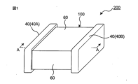
- FIG. 1 is a schematic external perspective view of a solid-state battery according to one embodiment of the present invention.
- FIG. 2 is a schematic cross-sectional view of the solid-state battery of FIG. 1 taken along line AA as viewed in the direction of the arrows.
- FIG. 3 is a graph showing the relationship between the heating temperature and the rate of thermogravimetric change (reduction) of the positive electrode active material in a solid-state battery according to one embodiment of the present invention.
- cross-sectional view refers to the shape of the solid-state battery when viewed from a direction approximately perpendicular to the stacking direction in the stacked structure (in simple terms, the shape when cut along a plane parallel to the thickness direction of the layers).
- planar view and planar shape used in this specification are based on a sketch of the object when viewed from above or below along the thickness direction of the layers (i.e., the stacking direction described above).
- the vertical downward direction i.e., the direction in which gravity acts
- the opposite direction to that corresponds to the "upward direction” can be considered to correspond to the vertical downward direction
- solid-state battery refers in a broad sense to a battery whose components are made of solids, and in a narrow sense to an all-solid-state battery whose components (particularly preferably all components) are made of solids.
- the solid-state battery of the present invention is a laminated solid-state battery in which the layers constituting the battery building blocks are stacked on top of each other, and preferably each such layer is made of a sintered body.
- a "solid-state battery” is a so-called “secondary battery” that can be repeatedly charged and discharged.
- the term “secondary battery” should not be overly limited to its name, and can also include, for example, a power storage device.
- the feature of the present invention relates to the positive electrode layer contained in the solid-state battery.
- the basic configuration of the solid-state battery of the present invention in order to understand the overall structure of the solid-state battery.
- the configuration of the solid-state battery explained here is merely an example for understanding the invention and does not limit the invention.
- Fig. 1 is a perspective view showing a schematic external appearance of a solid-state battery according to an embodiment of the present invention.
- Fig. 2 is a schematic cross-sectional view of the A-A cross section of the solid-state battery in Fig. 1 as viewed in the direction of the arrows.
- the solid-state battery has at least positive and negative electrode layers and a solid electrolyte.
- the solid-state battery 200 includes a solid-state battery stack 100 including battery constituent units consisting of a positive electrode layer 10A, a negative electrode layer 10B, and at least a solid electrolyte 20 interposed therebetween.
- a solid-state battery 200 comprises: a solid-state battery stack 100 including at least one battery constituent unit, arranged along a stacking direction L, the battery constituent unit being composed of a positive electrode layer 10A, a negative electrode layer 10B, and a solid electrolyte layer 20 interposed therebetween; and a positive electrode terminal 40A and a negative electrode terminal 40B provided on opposing side surfaces of the solid-state battery stack 100, respectively.
- the positive electrode layers 10A and the negative electrode layers 10B are stacked alternately with the solid electrolyte layer 20 interposed therebetween.
- each of the constituent layers may be formed by firing, and the positive electrode layer, negative electrode layer, solid electrolyte layer, etc. may form a fired layer.
- the positive electrode layer, negative electrode layer, and solid electrolyte layer are each fired integrally with each other, and the solid-state battery laminate forms an integrally fired body.
- the positive electrode layer is an electrode layer that includes at least a positive electrode active material.
- the positive electrode layer may further include a solid electrolyte.
- the positive electrode layer is composed of a sintered body that includes at least positive electrode active material particles and solid electrolyte particles.
- the negative electrode layer is an electrode layer that includes at least a negative electrode active material.
- the negative electrode layer may further include a solid electrolyte.
- the negative electrode layer is composed of a sintered body that includes at least negative electrode active material particles and solid electrolyte particles.
- a positive electrode layer having such a configuration is called a "composite positive electrode body," and similarly, a negative electrode layer can be called a "composite negative electrode body.”
- the positive electrode active material and the negative electrode active material are materials involved in the transfer of electrons in solid-state batteries. Charging and discharging are performed by the transfer of electrons as ions move (conduct) between the positive electrode layer and the negative electrode layer via the solid electrolyte. It is preferable that each electrode layer of the positive electrode layer and the negative electrode layer is a layer capable of absorbing and releasing lithium ions or sodium ions in particular. In other words, it is preferable that the solid-state battery is an all-solid-state secondary battery in which lithium ions or sodium ions move between the positive electrode layer and the negative electrode layer via the solid electrolyte to charge and discharge the battery.
- the content of the solid electrolyte in the positive electrode layer 10A is not particularly limited, and is usually 10 to 50 mass %, particularly preferably 20 to 40 mass %, based on the total amount of the positive electrode layer.
- the positive electrode layer may contain two or more types of solid electrolytes, in which case the total content thereof may be within the above range.
- the negative electrode active material contained in the negative electrode layer may be, for example, at least one selected from the group consisting of oxides containing at least one element selected from the group consisting of titanium (Ti), silicon (Si), tin (Sn), chromium (Cr), iron (Fe), niobium (Nb) and molybdenum (Mo), carbon materials such as graphite, graphite-lithium compounds, lithium alloys, lithium-containing phosphate compounds having a Nasicon structure, lithium-containing phosphate compounds having an olivine structure, and lithium-containing oxides having a spinel structure.
- An example of a lithium alloy is Li-Al.
- An example of a lithium-containing phosphate compound having a Nasicon structure is Li 3 V 2 (PO 4 ) 3 , and/or LiTi 2 (PO 4 ) 3 , and/or LiCuPO 4 , and the like.
- An example of a lithium-containing phosphate compound having an olivine structure is Li 3 Fe 2 (PO 4 ) 3 , and/or LiCuPO 4 , and the like.
- An example of a lithium-containing oxide having a spinel structure is Li 4 Ti 5 O 12 .
- the negative electrode active material capable of absorbing and releasing sodium ions may be at least one selected from the group consisting of sodium-containing phosphate compounds having a Nasicon structure, sodium-containing phosphate compounds having an olivine structure, and sodium-containing oxides having a spinel structure.
- the positive electrode layer and/or the negative electrode layer may contain a conductive material.
- the conductive material contained in the positive electrode layer and the negative electrode layer include at least one of metal materials such as silver, palladium, gold, platinum, aluminum, copper, and nickel, and carbon.
- the positive electrode layer and/or the negative electrode layer may contain a sintering aid.
- the sintering aid may be at least one selected from the group consisting of lithium oxide, sodium oxide, potassium oxide, boron oxide, silicon oxide, bismuth oxide, and phosphorus oxide.
- the thickness of the positive electrode layer and the negative electrode layer is not particularly limited, but may be, for example, independently 2 ⁇ m or more and 50 ⁇ m or less, particularly 5 ⁇ m or more and 30 ⁇ m or less.
- the positive electrode layer and the negative electrode layer may each include a positive electrode current collector layer 11A and a negative electrode current collector layer 11B.
- the positive electrode current collector layer and the negative electrode current collector layer may each have the form of a foil.
- the positive electrode current collector layer and the negative electrode current collector layer may each have the form of a sintered body.
- the positive electrode current collector constituting the positive electrode current collector layer and the negative electrode current collector constituting the negative electrode current collector it is preferable to use a material with high electrical conductivity, and for example, silver, palladium, gold, platinum, aluminum, copper, and/or nickel may be used.
- the positive electrode current collector and the negative electrode current collector may each have an electrical connection part for electrical connection to the outside, and may be configured to be electrically connectable to a terminal.
- the positive electrode current collecting layer and the negative electrode current collecting layer may be composed of a sintered body containing a conductive material and a sintering aid.
- the conductive material contained in the positive electrode current collecting layer and the negative electrode current collecting layer may be selected, for example, from materials similar to the conductive materials that may be contained in the positive electrode layer and the negative electrode layer.
- the sintering aid contained in the positive electrode current collecting layer and the negative electrode current collecting layer may be selected, for example, from materials similar to the sintering aids that may be contained in the positive electrode layer and the negative electrode layer.
- the solid electrolyte is a material capable of conducting lithium ions or sodium ions.
- the solid electrolyte may form a layer capable of conducting lithium ions between the positive electrode layer and the negative electrode layer.
- the solid electrolyte may also be included in the positive electrode layer and the negative electrode layer.
- the solid electrolyte layer may contain a sintering aid.
- the sintering aid contained in the solid electrolyte layer may be selected from materials similar to the sintering aids that may be contained in the positive electrode layer and the negative electrode layer, for example.
- the thickness of the solid electrolyte layer is not particularly limited.
- the thickness of the solid electrolyte layer located between the positive electrode layer and the negative electrode layer may be, for example, 1 ⁇ m or more and 15 ⁇ m or less, particularly 1 ⁇ m or more and 5 ⁇ m or less.
- the solid-state battery 200 of the present invention may further have an electrode separator (also called a "blank layer” or “blank portion”) 30 (30A, 30B).
- an electrode separator also called a "blank layer” or “blank portion” 30 (30A, 30B).
- the electrode separator 30A (positive electrode separator) is disposed around the positive electrode layer 10A, thereby separating the positive electrode layer 10A from the negative electrode terminal 40B.
- the electrode separator 30B (negative electrode separator) is disposed around the negative electrode layer 10B, thereby separating the negative electrode layer 10B from the positive electrode terminal 40A.
- the electrode separator 30 may be made of one or more materials selected from the group consisting of, for example, solid electrolytes, insulating materials, and mixtures thereof.
- the solid electrolyte that can form the electrode separator 30 can be made of the same material as the solid electrolyte that can form the solid electrolyte layer.
- the insulating material that may constitute the electrode separator 30 may be a material that does not conduct electricity, i.e., a non-conductive material.
- the insulating material may be, for example, a glass material, a ceramic material, or the like.
- a glass material may be selected.
- the glass material may be at least one selected from the group consisting of soda-lime glass, potash glass, borate-based glass, borosilicate-based glass, barium borosilicate-based glass, zinc borate-based glass, barium borate-based glass, bismuth borosilicate-based glass, bismuth zinc borate-based glass, bismuth silicate-based glass, phosphate-based glass, aluminophosphate-based glass, and zinc phosphate-based glass.
- the ceramic material may be at least one selected from the group consisting of aluminum oxide ( Al2O3 ), boron nitride (BN), silicon dioxide ( SiO2 ), silicon nitride ( Si3N4 ), zirconium oxide ( ZrO2 ), aluminum nitride ( AlN ), silicon carbide (SiC), and barium titanate ( BaTiO3 ).
- the solid-state battery 200 of the present invention is generally provided with terminals (external terminals) 40 (40A, 40B).
- positive and negative terminals 40A, 40B are provided in pairs on the side surfaces of the solid-state battery. More specifically, a positive terminal 40A connected to the positive electrode layer 10A and a negative terminal 40B connected to the negative electrode layer 10B are provided in pairs.
- the terminals 40A, 40B may also be referred to as "end electrodes" since they may be provided to cover at least one side surface of the solid-state battery.
- Such terminals 40 (40A, 40B) may be made of a material having a high electrical conductivity.
- the material of the terminal 40 is not particularly limited, but may be at least one conductive material selected from the group consisting of silver, gold, platinum, aluminum, copper, tin, and nickel.
- the terminal 40 (40A, 40B) may further contain a sintering aid.
- the sintering aid include materials similar to the sintering aid that may be contained in the positive electrode layer 10A.
- the terminal 40 (40A, 40B) is composed of a sintered body that contains at least a conductive material and a sintering aid.
- the solid-state battery 200 of the present invention usually further has an outer layer material 60.
- the outer layer material 60 can generally be formed on the outermost surface of the solid-state battery, and serves to provide electrical, physical, and/or chemical protection. It is preferable that the material constituting the outer layer material 60 is excellent in insulation, durability, and/or moisture resistance, and is environmentally safe. For example, glass, ceramics, thermosetting resin, photosetting resin, and mixtures thereof can be used.
- the same material as the glass material that can form the electrode separator can be used.
- the ceramic material that can form the outer layer material the same material as the ceramic material that can form the electrode separator can be used.
- the present inventors have intensively studied solutions that enable a solid-state battery to have more suitable battery characteristics even when used under high-temperature conditions. As a result, the present inventors have come up with a solution by focusing on the positive electrode layer that constitutes the solid-state battery. Specifically, the present inventors have newly discovered that, on the premise that the positive electrode layer contains a solid electrolyte of a specific material composition, the thermal weight loss onset temperature of a positive electrode active material containing Li (lithium) can be correlated with the battery characteristics under high-temperature conditions (i.e., high-temperature resistance).
- Figure 3 is a graph showing the relationship between the heating temperature and the rate of thermogravimetric change (reduction) of the positive electrode active material in a solid-state battery according to one embodiment of the present invention.
- the rate of thermogravimetric change (reduction) of the positive electrode active material increases from a certain temperature onwards.
- the figure also shows two TG (Thermogravimetry) curves (the TG curve for Example 1 and the TG curve for Comparative Example 1) with different temperatures at which the thermogravimetric reduction starts (i.e., the thermogravimetric reduction onset temperature).
- thermogravimetric reduction onset temperature differs depending on the material composition of the positive electrode active material and solid electrolyte contained in the positive electrode layer, and the different thermogravimetric reduction onset temperatures may be correlated with the battery characteristics under high temperature conditions.
- a positive electrode active material with a thermal weight loss onset temperature in a specific range is preferably selected for the positive electrode layer under the condition that the positive electrode layer contains a solid electrolyte with a specific material composition.
- a positive electrode active material can be selected that has a thermal weight loss onset temperature of 220°C or higher and lower than 485°C at which the weight is reduced by 0.67% or more when the amount of lithium desorbed from the positive electrode active material is 40% (i.e., when 40% of the Li amount in the positive electrode active material is desorbed), under the condition that the positive electrode layer contains lithium borosilicate glass as the solid electrolyte.
- a positive electrode layer having the above characteristics for a solid battery it is possible to provide a battery with more suitable battery characteristics under high temperature conditions. In other words, a solid battery with superior high temperature resistance can be provided.
- the solid-state battery of the present invention can be suitably used even under high-temperature conditions.
- the lower limit of the temperature at which the thermal weight loss of the positive electrode active material begins (220°C or higher) contributes to maintaining the high-temperature resistance of the solid-state battery
- the upper limit (less than 485°C) is based on the viewpoint of suppressing the decrease in the electronic conductivity of the positive electrode active material.
- the upper limit of the temperature at which the thermal weight loss begins can be 350°C or lower.
- the temperature at which the weight loss of the positive electrode active material begins to decrease due to heat can be measured using a simultaneous thermogravimetry and differential thermal analysis device (manufactured by Rigaku Corporation, model number TG8120). Specifically, a sample (positive electrode layer, etc.) is set in this device, and heated under conditions of a specified heating rate while nitrogen is flowing at a specified rate, and the temperature at which the weight loss of the positive electrode active material begins to decrease by 0.67% or more is measured. When the sample is heated in this device, a weight change occurs in the positive electrode active material contained in the positive electrode layer from a specified temperature value. When this weight change occurs, the main beam in this measurement device tilts, and the current flowing through the coil is controlled to return the movement to its original position. Since the current flows in response to the weight change, the fluctuation behavior of the current is output as a weight change, and the temperature at which the weight loss of the positive electrode active material begins to decrease due to heat can be determined.
- a simultaneous thermogravimetry and differential thermal analysis device manufactured by Ri
- a state in which the amount of lithium released from the positive electrode active material is 40% refers to a state in which the amount of lithium released is 40% when the amount of lithium released is expressed as a percentage relative to the lithium content of the positive electrode active material.
- a state in which the amount of lithium released from the positive electrode active material is 40% means a state in which the lithium content of the positive electrode active material in an uncharged battery is 100% and the lithium content of the positive electrode active material is 60%.
- a state in which the amount of lithium released from the positive electrode active material is 40% can be a charged state in which 40% of the lithium content of the positive electrode active material in a battery at full discharge has been extracted.
- the state of Li extracted from the positive electrode active material can be measured using XRD.
- the reason for evaluating the thermogravimetric loss onset temperature of the positive electrode active material in a state where the amount of lithium desorbed from the positive electrode active material contained in the positive electrode layer is 40% is as follows.
- the crystal structure of the positive electrode active material can become unstable due to the extraction of lithium. This instability is observed from the charging state where 40% of the Li amount of the positive electrode active material has been desorbed, and can be particularly noticeable under high temperature battery usage conditions. Due to this instability of the crystal structure, degradation of the solid-state battery can easily progress under high temperature conditions when 40% of the Li amount of the positive electrode active material has been desorbed. For these reasons, the thermogravimetric loss onset temperature of the positive electrode active material in a state where 40% of the Li amount of the positive electrode active material has been desorbed is evaluated.
- the amount of lithium desorption can be quantified by XRD analysis. Alternatively, it can be calculated from the charge amount of the solid-state battery based on the initial charge/discharge efficiency and the weight of the positive and negative active materials.
- the lithium borosilicate glass contained in the positive electrode layer is an oxide-based glass material containing at least lithium (Li), silicon (Si) and boron (B) as constituent elements, and can be, for example, 50Li 4 SiO 4 ⁇ 50Li 3 BO 3. Since such a solid electrolyte has relatively high thermal stability, by containing it in the positive electrode layer, it may be possible to more suitably suppress the deterioration of the battery characteristics of the solid-state battery under high temperature conditions.
- the lithium borosilicate glass may further contain one or more additional elements in addition to lithium, silicon, boron, and oxygen.
- the lithium borosilicate glass may further contain at least one element selected from the group consisting of Groups 1 and 2 and Groups 14 to 17 of the Periodic Table.
- the content of each element contained in the lithium borosilicate glass can be measured by analyzing the glass-ceramic solid electrolyte using, for example, inductively coupled plasma atomic emission spectroscopy (ICP-AES).
- the solid electrolyte may further include a solid electrolyte used in other known solid-state batteries in addition to the lithium borosilicate glass as a glass-based solid electrolyte.
- a solid electrolyte may be, for example, one or more of a crystalline solid electrolyte, a glass-based solid electrolyte other than lithium borosilicate glass, and a glass ceramic-based solid electrolyte.
- the crystalline solid electrolyte is, for example, an oxide-based crystal material.
- oxide-based crystal material examples include a lithium-containing phosphate compound having a Nasicon structure, an oxide having a perovskite structure, an oxide having a garnet-type or garnet-like structure, and an oxide glass ceramic-based lithium ion conductor.
- An example of a lithium-containing phosphate compound having a Nasicon structure is Li x M y (PO 4 ) 3 (1 ⁇ x ⁇ 2, 1 ⁇ y ⁇ 2, M is at least one selected from the group consisting of titanium (Ti), germanium (Ge), aluminum (Al), gallium (Ga) and zirconium (Zr).
- An example of a lithium-containing phosphate compound having a Nasicon structure is Li 1.2 Al 0.2 Ti 1.8 (PO 4 ) 3.
- An example of an oxide having a perovskite structure is La 0.55 Li 0.35 TiO 3.
- An example of an oxide having a garnet type or a garnet type-like structure is Li 7 La 3 Zr 2 O 12.
- the crystalline solid electrolyte may contain a polymer material (e.g., polyethylene oxide (PEO)).
- the glass-based solid electrolyte may be, for example, an oxide- based glass material , etc.
- glass - based solid electrolytes other than lithium borosilicate glass include 30Li2S.26B2S3.44LiI , 63Li2S.36SiS2.1Li3PO4 , 57Li2S.38SiS2.5Li4SiO4 , 70Li2S.30P2S5 , and 50Li2S.50GeS2 .
- the glass ceramic solid electrolyte may be, for example, an oxide-based glass ceramic material.
- a phosphate compound containing lithium, aluminum, and titanium as constituent elements (LATP) or a phosphate compound containing lithium, aluminum, and germanium as constituent elements (LAGP) may be used as the oxide - based glass ceramic material.
- LATP is Li1.07Al0.69Ti1.46 ( PO4 ) 3 .
- LAGP is Li1.5Al0.5Ge1.5 ( PO4 ).
- the solid electrolyte may further include an oxide having a garnet-type or garnet-type similar structure in addition to lithium borosilicate glass.
- the positive electrode layer of the solid battery of the present invention may include lithium borosilicate glass and an oxide containing Li, La, and Zr (corresponding to LiLaZr-based oxide) as a solid electrolyte. The present inventors have found that when the positive electrode layer includes at least lithium borosilicate glass as a solid electrolyte, the positive electrode active material can preferentially form an interface with lithium borosilicate glass, which has relatively high thermal stability.
- the lithium borosilicate glass can suppress the reaction between the positive electrode active material and the solid electrolyte with low thermal stability under high temperature conditions. Therefore, it is possible to further include another solid electrolyte that is inferior in thermal stability to lithium borosilicate glass but has excellent lithium ion conductivity, and a solid battery that more suitably balances high temperature resistance and battery performance (e.g., capacity retention rate, etc.) can be obtained.
- the content of lithium borosilicate glass in the solid electrolyte of the positive electrode layer is not particularly limited, but can be, for example, 10 to 90 mass%, 30 to 80 mass%, or 40 to 60 mass% relative to the total amount of solid electrolyte in the positive electrode layer.
- the content of garnet-type oxide solid electrolyte in the solid electrolyte of the positive electrode layer is not particularly limited, but can be, for example, 0 to 70 mass%, 5 to 60 mass%, or 10 to 40 mass% relative to the total amount of solid electrolyte in the positive electrode layer. If the content of garnet-type oxide solid electrolyte is within the above range, a solid battery that can be used more suitably even under high temperature conditions can be provided.
- such an oxide-based solid electrolyte may be a LiLaZr-based oxide (LLZ) with high ionic conductivity.
- LLZ LiLaZr-based oxide
- two or more types of solid electrolytes may be used: a solid electrolyte that contributes to thermal stability and a solid electrolyte that contributes to high ionic conductivity. This may make it possible to maintain battery characteristics under high temperature conditions and ensure ionic conductivity that contributes to charging and discharging the battery.
- the positive electrode active material may have a layered crystal structure.
- the positive electrode active material may be a layered rock-salt type metal oxide, for example, a lithium transition metal composite oxide.
- "Layered rock-salt type metal oxide” refers to a metal oxide, particularly particles thereof, having a layered rock-salt type crystal structure that can be identified by analyzing an X-ray diffraction diagram.
- the positive electrode active material contains an oxide containing Li and Co (equivalent to LCO, which corresponds to a LiCo-based oxide), and this LiCo-based oxide may contain at least Ti. This makes it possible to increase the temperature at which the thermal weight loss of the positive electrode active material begins to decrease compared to a case in which Ti is not contained, and makes it possible to maintain the battery characteristics under high temperature conditions.
- this LiCo-based oxide may further contain at least one element selected from the group consisting of Mg, Al, Ni, Mn, Zr, Zn, Cu, B, P, Si, Ge, Nb, Au, and Pt.
- the positive electrode active material is a LiCo-based oxide containing at least Ti
- its thermal weight loss onset temperature may be 220°C or higher and 240°C or lower.
- ⁇ is more preferably Al and/or Mg.
- the positive electrode active material may include an oxide containing Li, Ni, Co, and Mn (equivalent to NCM, which corresponds to LiNiCoMn-based oxide).
- the positive electrode active material may be LiNi a Co b Mn c O 2 (wherein a + b + c ⁇ 1, 0.3 ⁇ a ⁇ 0.8).
- the above-mentioned thermal weight loss onset temperature can be higher when the positive electrode active material is a LiNiCoMn-based oxide than when the positive electrode active material is a LiCo-based oxide containing Ti.
- the thermal weight loss onset temperature of the positive electrode active material can be made higher, making it possible to have more favorable battery characteristics under high temperature conditions.
- the solid-state battery of the present invention can be manufactured by a printing method such as a screen printing method, a green sheet method using a green sheet, or a combination of these methods.
- a printing method such as a screen printing method, a green sheet method using a green sheet, or a combination of these methods.
- the solid-state battery may be manufactured in accordance with a conventional method for manufacturing a solid-state battery.
- the chronological matters such as the order of description below are merely for the convenience of explanation and are not necessarily bound by them.
- pastes are used as inks, such as a paste for a positive electrode layer, a paste for a negative electrode layer, a paste for a solid electrolyte layer, a paste for a positive electrode current collector layer, a paste for a negative electrode current collector layer, a paste for an electrode separator, and a paste for an outer layer material, etc.
- the pastes are applied by a printing method and dried to form a solid-state battery laminate precursor having a predetermined structure on a support base.
- a solid-state battery laminate precursor that corresponds to the structure of a specified solid-state battery can be formed on the substrate by sequentially stacking printed layers with a specified thickness and pattern shape.
- the type of pattern formation method is not particularly limited as long as it is a method capable of forming a specified pattern, but may be, for example, one or more of the following: screen printing and gravure printing.
- the paste can be prepared by wet mixing the specific constituent materials for each layer appropriately selected from the group consisting of positive electrode active material particles, negative electrode active material particles, conductive material, solid electrolyte material, current collector layer material, insulating material, sintering aid, and other materials mentioned above, with an organic vehicle in which an organic material is dissolved in a solvent.
- the paste for the positive electrode layer contains, for example, positive electrode active material particles, a solid electrolyte material, an organic material and a solvent, and optionally a sintering aid.
- the paste for the negative electrode layer contains, for example, negative electrode active material particles, a solid electrolyte material, an organic material and a solvent, and optionally a sintering aid.
- the paste for the solid electrolyte layer contains, for example, a solid electrolyte material, an organic material, and a solvent, and optionally a sintering aid.
- the paste for the positive electrode current collecting layer contains a conductive material, an organic material, a solvent, and optionally a sintering aid.
- the paste for the negative electrode current collecting layer contains a conductive material, an organic material, a solvent, and optionally a sintering aid.
- the paste for the electrode separator contains, for example, a solid electrolyte material, an insulating material, an organic material, a solvent, and optionally a sintering aid.
- the paste for the outer layer material contains, for example, an insulating material, an organic material, a solvent, and optionally a sintering aid.
- the organic material contained in the paste is not particularly limited, but at least one polymeric material selected from the group consisting of polyvinyl acetal resin, cellulose resin, polyacrylic resin, polyurethane resin, polyvinyl acetate resin, polyvinyl alcohol resin, etc. can be used.
- the type of solvent is not particularly limited, but may be, for example, one or more of organic solvents such as butyl acetate, N-methyl-pyrrolidone, toluene, terpineol, and N-methyl-pyrrolidone.
- media can be used, specifically, the ball mill method or the viscomill method, etc. can be used.
- wet mixing methods that do not use media can also be used, such as the sand mill method, the high-pressure homogenizer method, or the kneader dispersion method.
- the supporting substrate is not particularly limited as long as it is capable of supporting each paste layer, but for example, it may be a release film with one surface treated for release. Specifically, a substrate made of a polymeric material such as polyethylene terephthalate may be used. If the paste layer is subjected to a firing process while being held on the substrate, a substrate that is heat resistant to the firing temperature may be used.
- green sheets can be formed from each paste and the resulting green sheets can be stacked to produce a solid-state battery laminate precursor.
- the support base coated with each paste is dried on a hot plate heated to 30°C to 90°C to form a positive electrode layer green sheet, a negative electrode layer green sheet, a solid electrolyte layer green sheet, a positive electrode current collector layer green sheet, a negative electrode current collector layer green sheet, an electrode separator green sheet, and/or an outer layer green sheet, each having a predetermined shape and thickness, on each support base (e.g., a PET film).
- a hot plate heated to 30°C to 90°C to form a positive electrode layer green sheet, a negative electrode layer green sheet, a solid electrolyte layer green sheet, a positive electrode current collector layer green sheet, a negative electrode current collector layer green sheet, an electrode separator green sheet, and/or an outer layer green sheet, each having a predetermined shape and thickness, on each support base (e.g., a PET film).
- each green sheet is peeled off from the substrate. After peeling, the green sheets of each component are stacked in order along the stacking direction to form a solid-state battery stack precursor. After stacking, a solid electrolyte layer, an insulating layer, and/or a protective layer may be provided on the side regions of the electrode green sheets by screen printing.
- the solid battery laminate precursor is subjected to firing.
- firing is performed by heating in an oxygen-containing nitrogen gas atmosphere or in the air, for example at 200° C. or higher to remove organic materials, and then heating in a nitrogen gas atmosphere or in the air, for example at 300° C. or higher.
- the firing may be performed while applying pressure to the solid battery laminate precursor in the stacking direction (and in some cases in the stacking direction and in a direction perpendicular to the stacking direction).
- a positive terminal is attached to the solid-state battery stack using a conductive adhesive
- a negative terminal is attached to the solid-state battery stack using a conductive adhesive, thereby attaching the positive terminal and the negative terminal to the solid-state battery stack, and finally, a desired solid-state battery can be obtained.
- the obtained mixture was mixed with butyl acetate so that the solid content was 30 mass%, and then stirred with a zirconia ball having a diameter of 5 mm for 4 hours to obtain a paste for a solid electrolyte layer.
- the paste was applied on a release film and dried at 80 ° C for 10 minutes to prepare a green sheet for a solid electrolyte layer as a solid electrolyte layer precursor.
- the obtained mixture was then stirred for 4 hours with zirconia balls having a diameter of 5 mm to obtain a paste for the positive electrode layer.
- this paste was applied onto a release film and dried at 80 ° C for 10 minutes to produce a green sheet for the positive electrode layer as a positive electrode layer precursor.
- the obtained mixture was stirred with a zirconia ball having a diameter of 5 mm for 4 hours to obtain a paste for the negative electrode material layer.
- this paste was applied to a release film and dried at 80 ° C for 10 minutes to prepare a green sheet for the negative electrode material layer as a precursor of the negative electrode material layer.
- the obtained mixture was stirred with a zirconia ball having a diameter of 5 mm for 4 hours to obtain a paste for a positive electrode current collector layer.
- this paste was applied on a release film and dried at 80 ° C. for 10 minutes to produce a green sheet for a positive electrode current collector layer as a positive electrode current collector layer precursor.
- a green sheet for a negative electrode current collecting layer was prepared in the same manner as in the above-mentioned process for preparing the green sheet for a positive electrode current collecting layer.
- the obtained mixture was stirred with zirconia balls having a diameter of 5 mm for 4 hours to obtain a paste for main surface exterior material.
- this paste was applied on a release film and dried to prepare a green sheet for outer layer material as an outer layer material precursor.
- a laminate having the configuration shown in Figures 1 and 2 was produced as follows. Specifically, first, each green sheet was processed into the shape shown in Figures 1 and 2, and then released from the release film. Next, each green sheet was laminated in order so as to correspond to the configuration of the battery element shown in Figures 1 and 2, and then thermocompression bonded. In this way, a laminate was obtained as a battery element precursor.
- this conductive paste was attached to the first and second end faces (or side faces) of the laminate where the positive electrode current collecting layer and the negative electrode current collecting layer were exposed, respectively, and sintered to form positive and negative electrode terminals. As a result, a solid battery in Example 1 was obtained.
- Example 2 LiNi0.3Co0.3Mn0.3O2 was synthesized as the positive electrode active material in the process of producing the positive electrode layer green sheet in Example 1. A solid- state battery was produced in the same manner as in Example 1 except for this point.
- Example 3 In Example 3, in the process of producing a green sheet for a positive electrode material layer in Example 1 , LiNi0.72Co0.05Mn0.2O2 having a composition different from that in Examples 1 and 2 was synthesized as a positive electrode active material. A solid-state battery was produced in the same manner as in Example 1 except for this point.
- Example 4 In Example 4, in the process of producing the green sheet for the positive electrode material layer in Example 1, cobalt oxide, lithium carbonate, and titanium were mixed and sintered to synthesize titanium-containing lithium cobalt oxide (LiCoO 2 ) by a solid-phase method. Specifically, in Example 4, LiCo 0.995 Ti 0.005 O 2 was synthesized as the positive electrode active material. Except for this point, a solid-state battery was produced by the same method as in Example 1.
- Example 5 in the process of producing the green sheet for the positive electrode layer in Example 1, LiCo0.99Ti0.01O2 having a composition different from that in Example 4 was synthesized as the positive electrode active material. A solid-state battery was produced in the same manner as in Example 1 except for this point.
- Example 6 lithium cobalt oxide (LiCoO 2 ) containing titanium and aluminum was synthesized by a solid-phase method in which cobalt oxide, lithium carbonate, titanium, and aluminum were mixed and sintered in the process of producing the green sheet for the positive electrode layer in Example 1. Specifically, in Example 6, LiCo 0.985 Ti 0.005 Al 0.01 O 2 was synthesized as the positive electrode active material. Except for this point, a solid-state battery was manufactured by the same method as in Example 1.
- Example 7 in the process of producing a green sheet for a positive electrode material layer in Example 1, LiCo0.965Ti0.005Al0.03O2 having a composition different from that in Example 6 was synthesized as a positive electrode active material. A solid-state battery was produced in the same manner as in Example 1 except for this point.
- Example 8 in the process of producing a green sheet for a positive electrode material layer in Example 1, LiCo0.945Ti0.005Al0.05O2 having a composition different from that in Examples 6 and 7 was synthesized as a positive electrode active material. A solid-state battery was produced in the same manner as in Example 1 except for this point.
- Example 9 lithium cobalt oxide (LiCoO 2 ) containing titanium and magnesium was synthesized by a solid-phase method in which cobalt oxide, lithium carbonate, titanium and magnesium were mixed and sintered in the process of producing a green sheet for a positive electrode material layer in Example 1. Specifically, in Example 9, LiCo 0.985 Ti 0.005 Mg 0.01 O 2 was synthesized as the positive electrode active material. Apart from this, a solid-state battery was manufactured by the same method as in Example 1.
- Example 10 In Example 10, in the process of producing a green sheet for a positive electrode material layer in Example 1 , LiCo0.965Ti0.005Mg0.03O2 having a composition different from that in Example 9 was synthesized as a positive electrode active material. A solid-state battery was produced in the same manner as in Example 1 except for this point.
- Example 11 In Example 11, in the process of producing a green sheet for a positive electrode layer in Example 1 , LiCo0.945Ti0.005Mg0.05O2 having a composition different from that in Examples 9 and 10 was synthesized as a positive electrode active material. A solid-state battery was produced in the same manner as in Example 1 except for this point.
- Example 12 in Example 12, in the process of preparing the green sheet for the positive electrode material layer in Example 1 , LiCo0.995Ti0.005O2 having the same composition as in Example 4 was synthesized as the positive electrode active material.
- Example 1 A solid-state battery was produced in the same manner as in Example 1, except that lithium cobalt oxide not containing titanium was used as the positive electrode active material.
- Example 2 A solid-state battery was produced in the same manner as in Example 4, except that a LiLaZr-based oxide was used as the solid electrolyte. Li 7 La 3 Zr 2 O 12 was used as the LiLaZr-based oxide.
- Example 3 A solid-state battery was produced in the same manner as in Example 1, except that an oxide containing Li, Mn, and Al (corresponding to a LiMnAl-based oxide) was used as the solid electrolyte.
- an oxide containing Li, Mn, and Al corresponding to a LiMnAl-based oxide
- LiMnAl-based oxide LiMn1.92Al0.08O4 (LMO) was used.
- the rated capacity of the battery was 1C, and the battery was charged to a predetermined positive electrode potential at a constant current of 0.2C. After the positive electrode potential was reached, the battery was charged in a constant voltage mode until the current was reduced to 0.01C, and impedance measurement was performed to obtain the initial resistance value. After that, the battery was stored under high temperature conditions (105°C) for one week, and slowly cooled to 25°C by air cooling, and then impedance measurement was performed at 25°C, and the battery was discharged to 2V at a constant current of 0.2C, and capacity measurement was performed.
- the positive electrode potential was different depending on the positive electrode active material.
- the positive electrode active material was LiCo-based oxide (LCO)
- charging was performed to a positive electrode potential of 4.35V
- the positive electrode active material was LiNiCoMn-based oxide (NCM)
- charging was performed to a positive electrode potential of 4.2V
- the positive electrode active material was LiMnAl-based oxide (LMO)
- charging was performed to a positive electrode potential of 4.95V.
- the initial resistance value obtained from the impedance measurement was divided by the resistance value after storage under high-temperature conditions to calculate the resistance increase rate.
- the deterioration capacity of the discharge capacity after storage under high-temperature conditions was obtained from the capacity measurement results.
- the capacity retention rate was measured for the solid-state batteries of Examples 1, 2, 4 to 12 and Comparative Examples 1 to 3. Specifically, the rated capacity of the battery was set to 1C, and the battery was charged to the above-mentioned positive electrode potential with a constant current of 0.2C, and after the positive electrode potential was reached, the battery was charged in a constant voltage mode until the current was reduced to 0.01C. Then, the battery was discharged at a constant current of 0.2C until the positive electrode potential reached 3V. Such charging and discharging was counted as one cycle, and the capacity retention rate relative to the initial discharge capacity was measured after 100 cycles were repeated.
- the positive electrode layer was set in a thermogravimetric and differential thermal analysis (TG-DTA) device (manufactured by Rigaku Corporation, device model number: TG8120) and heated under conditions of a temperature increase rate of 3°C min while flowing nitrogen at a rate of 200 ml/min, and the thermogravimetric reduction start temperature of the positive electrode active material at which the weight of the positive electrode active material contained in the positive electrode layer at the start of the measurement was reduced by 0.67% or more was measured. Specifically, as the temperature is increased, a weight change of the positive electrode active material occurs from a predetermined temperature value.
- TG-DTA thermogravimetric and differential thermal analysis
- the main beam in the device tilts, and the current flowing through the coil is controlled to return the movement to the original state. Since the current flow corresponds to the weight change, the fluctuation behavior of the current is output as a weight change, and the thermogravimetric reduction start temperature of the positive electrode active material described above was grasped.
- the weight of the positive electrode active material at the start of the measurement can be calculated from the weight of the positive electrode layer and the mixing ratio of the positive electrode active material in the positive electrode layer.
- Comparative Example 2 thermo weight loss onset temperature: 210°C + solid electrolyte in the positive electrode layer: containing LiLaZr-based oxide/not containing lithium borosilicate glass
- the relative degradation capacity of the solid-state battery was even lower than that of Comparative Example 1.
- the present invention can take the following forms.
- a positive electrode layer including a positive electrode active material containing Li and a solid electrolyte, a thermal weight loss onset temperature at which the weight of the positive electrode active material decreases by 0.67% or more when the amount of lithium desorbed from the positive electrode active material is 40% is 220° C. or higher and lower than 485° C.
- the solid electrolyte contains lithium borosilicate glass.
- the thermal weight loss starting temperature is 350° C. or lower.
- ⁇ 4> The solid-state battery according to any one of ⁇ 1> to ⁇ 3>, wherein the positive electrode active material contains an oxide containing Li and Co, and the oxide contains at least Ti.
- ⁇ 5> The solid-state battery according to ⁇ 4>, wherein, in the positive electrode active material, when the oxide containing Li and Co contains Ti, the thermal weight loss starting temperature is 220° C. or higher and 240° C. or lower.
- ⁇ 6> The solid-state battery according to ⁇ 4> or ⁇ 5>, wherein the positive electrode active material further contains Mg and/or Al.
- ⁇ 8> The solid-state battery according to any one of ⁇ 1> to ⁇ 7>, wherein the positive electrode active material contains an oxide containing Li, Ni, Co, and Mn.
- ⁇ 9> The solid-state battery according to ⁇ 8>, wherein the positive electrode active material is LiNi a Co b Mn c O 2 (wherein a + b + c ⁇ 1, 0.3 ⁇ a ⁇ 0.8).
- ⁇ 10> The solid-state battery according to any one of ⁇ 1> to ⁇ 9>, wherein the thermal weight loss starting temperature is higher when the positive electrode active material is an oxide containing Li, Ni, Co, and Mn than when the positive electrode active material is an oxide containing Li and Co and Ti.
- the oxide-based solid electrolyte is an oxide containing Li, La, and Zr.
- the solid-state battery of the present invention can be used in various fields where power storage is expected.
- the solid-state battery of the present invention can be used in the electrical, information, and communication fields where mobile devices are used (for example, the electrical and electronic devices fields or mobile device fields including small electronic devices such as mobile phones, smartphones, notebook computers, digital cameras, activity meters, arm computers, electronic paper, RFID tags, card-type electronic money, and smart watches), household and small industrial applications (for example, power tools, golf carts, household, nursing care, and industrial robots), large industrial applications (for example, forklifts, elevators, and port cranes), transportation systems (for example, hybrid cars, electric cars, buses, trains, electrically assisted bicycles, and electric motorcycles), power system applications (for example, various power generation, road conditioners, smart grids, and general household installation-type power storage systems), medical applications (medical devices such as earphones and hearing aids), pharmaceutical applications (medical management systems), and the IoT field, and space and deep sea applications (for example, space probes, sub
- Electrode layer 10A Positive electrode layer 10B: Negative electrode layer 11: Electrode current collector layer 11A: Positive electrode current collector layer 11B: Negative electrode current collector layer 20: Solid electrolyte layer 30: Electrode separator 30A: Positive electrode separator 30B: Negative electrode separator 40: Terminal 40A: Positive electrode terminal 40B: Negative electrode terminal 60: Outer layer material 100: Solid-state battery laminate 200: Solid-state battery
Landscapes
- Chemical & Material Sciences (AREA)
- General Chemical & Material Sciences (AREA)
- Chemical Kinetics & Catalysis (AREA)
- Electrochemistry (AREA)
- Engineering & Computer Science (AREA)
- Manufacturing & Machinery (AREA)
- Materials Engineering (AREA)
- Inorganic Chemistry (AREA)
- Physics & Mathematics (AREA)
- Condensed Matter Physics & Semiconductors (AREA)
- General Physics & Mathematics (AREA)
- Secondary Cells (AREA)
- Battery Electrode And Active Subsutance (AREA)
Priority Applications (3)
| Application Number | Priority Date | Filing Date | Title |
|---|---|---|---|
| CN202380088280.3A CN120345076A (zh) | 2023-01-13 | 2023-12-15 | 固体电池 |
| JP2024570104A JPWO2024150604A1 (https=) | 2023-01-13 | 2023-12-15 | |
| US19/245,855 US20250316752A1 (en) | 2023-01-13 | 2025-06-23 | Solid-state battery |
Applications Claiming Priority (2)
| Application Number | Priority Date | Filing Date | Title |
|---|---|---|---|
| JP2023004053 | 2023-01-13 | ||
| JP2023-004053 | 2023-01-13 |
Related Child Applications (1)
| Application Number | Title | Priority Date | Filing Date |
|---|---|---|---|
| US19/245,855 Continuation US20250316752A1 (en) | 2023-01-13 | 2025-06-23 | Solid-state battery |
Publications (1)
| Publication Number | Publication Date |
|---|---|
| WO2024150604A1 true WO2024150604A1 (ja) | 2024-07-18 |
Family
ID=91896807
Family Applications (1)
| Application Number | Title | Priority Date | Filing Date |
|---|---|---|---|
| PCT/JP2023/045081 Ceased WO2024150604A1 (ja) | 2023-01-13 | 2023-12-15 | 固体電池 |
Country Status (4)
| Country | Link |
|---|---|
| US (1) | US20250316752A1 (https=) |
| JP (1) | JPWO2024150604A1 (https=) |
| CN (1) | CN120345076A (https=) |
| WO (1) | WO2024150604A1 (https=) |
Citations (5)
| Publication number | Priority date | Publication date | Assignee | Title |
|---|---|---|---|---|
| JPH10144351A (ja) * | 1996-09-13 | 1998-05-29 | Matsushita Electric Ind Co Ltd | 全固体リチウム二次電池と集合電池およびその充電方法 |
| JP2014096352A (ja) * | 2012-11-07 | 2014-05-22 | Ngk Insulators Ltd | セラミック正極−固体電解質複合体 |
| JP2018141242A (ja) * | 2014-01-08 | 2018-09-13 | イリカ テクノロジーズ リミテッド | リチウム含有薄膜層状構造を製造するための蒸着方法 |
| CN108899486A (zh) * | 2018-06-14 | 2018-11-27 | 中国人民解放军国防科技大学 | 包覆硫系电解质的正极活性材料及其制备方法、全固态锂硫电池及其制备方法 |
| JP2019518311A (ja) * | 2016-06-15 | 2019-06-27 | イリカ テクノロジーズ リミテッド | 電解質および電極保護層としてのホウケイ酸リチウムガラス |
-
2023
- 2023-12-15 WO PCT/JP2023/045081 patent/WO2024150604A1/ja not_active Ceased
- 2023-12-15 JP JP2024570104A patent/JPWO2024150604A1/ja active Pending
- 2023-12-15 CN CN202380088280.3A patent/CN120345076A/zh active Pending
-
2025
- 2025-06-23 US US19/245,855 patent/US20250316752A1/en active Pending
Patent Citations (5)
| Publication number | Priority date | Publication date | Assignee | Title |
|---|---|---|---|---|
| JPH10144351A (ja) * | 1996-09-13 | 1998-05-29 | Matsushita Electric Ind Co Ltd | 全固体リチウム二次電池と集合電池およびその充電方法 |
| JP2014096352A (ja) * | 2012-11-07 | 2014-05-22 | Ngk Insulators Ltd | セラミック正極−固体電解質複合体 |
| JP2018141242A (ja) * | 2014-01-08 | 2018-09-13 | イリカ テクノロジーズ リミテッド | リチウム含有薄膜層状構造を製造するための蒸着方法 |
| JP2019518311A (ja) * | 2016-06-15 | 2019-06-27 | イリカ テクノロジーズ リミテッド | 電解質および電極保護層としてのホウケイ酸リチウムガラス |
| CN108899486A (zh) * | 2018-06-14 | 2018-11-27 | 中国人民解放军国防科技大学 | 包覆硫系电解质的正极活性材料及其制备方法、全固态锂硫电池及其制备方法 |
Also Published As
| Publication number | Publication date |
|---|---|
| CN120345076A (zh) | 2025-07-18 |
| JPWO2024150604A1 (https=) | 2024-07-18 |
| US20250316752A1 (en) | 2025-10-09 |
Similar Documents
| Publication | Publication Date | Title |
|---|---|---|
| JP7553352B2 (ja) | 全固体電池 | |
| JP7484999B2 (ja) | 固体電池 | |
| JP7107389B2 (ja) | 固体電池 | |
| US12489146B2 (en) | Solid state battery | |
| WO2020250981A1 (ja) | 固体電池 | |
| US20220320590A1 (en) | Solid state battery | |
| JP7405151B2 (ja) | 固体電池 | |
| US20220140388A1 (en) | Solid-state battery | |
| JP7435615B2 (ja) | 固体電池 | |
| CN113597688A (zh) | 固体电池 | |
| JP7375832B2 (ja) | 固体電池 | |
| JP7803440B2 (ja) | 固体電池 | |
| JP7762070B2 (ja) | 積層型全固体電池 | |
| WO2024150604A1 (ja) | 固体電池 | |
| WO2021132500A1 (ja) | 固体電池 | |
| JP7798120B2 (ja) | 固体電池 | |
| JP7509195B2 (ja) | 固体電池 | |
| WO2024202358A1 (ja) | 固体電池 | |
| JP7259938B2 (ja) | 固体電池 | |
| WO2024202357A1 (ja) | 固体電池 | |
| WO2025033068A1 (ja) | 固体電池 | |
| WO2025028617A1 (ja) | 固体電池 | |
| WO2023171457A1 (ja) | 固体電池および固体電池が表面実装された電子デバイス |
Legal Events
| Date | Code | Title | Description |
|---|---|---|---|
| 121 | Ep: the epo has been informed by wipo that ep was designated in this application |
Ref document number: 23916218 Country of ref document: EP Kind code of ref document: A1 |
|
| WWE | Wipo information: entry into national phase |
Ref document number: 202380088280.3 Country of ref document: CN |
|
| ENP | Entry into the national phase |
Ref document number: 2024570104 Country of ref document: JP Kind code of ref document: A |
|
| WWE | Wipo information: entry into national phase |
Ref document number: 2024570104 Country of ref document: JP |
|
| WWP | Wipo information: published in national office |
Ref document number: 202380088280.3 Country of ref document: CN |
|
| NENP | Non-entry into the national phase |
Ref country code: DE |
|
| 122 | Ep: pct application non-entry in european phase |
Ref document number: 23916218 Country of ref document: EP Kind code of ref document: A1 |