WO2024150540A1 - ガイドワイヤ - Google Patents
ガイドワイヤ Download PDFInfo
- Publication number
- WO2024150540A1 WO2024150540A1 PCT/JP2023/041713 JP2023041713W WO2024150540A1 WO 2024150540 A1 WO2024150540 A1 WO 2024150540A1 JP 2023041713 W JP2023041713 W JP 2023041713W WO 2024150540 A1 WO2024150540 A1 WO 2024150540A1
- Authority
- WO
- WIPO (PCT)
- Prior art keywords
- core shaft
- tubular member
- guidewire
- protrusion
- rear end
- Prior art date
- Legal status (The legal status is an assumption and is not a legal conclusion. Google has not performed a legal analysis and makes no representation as to the accuracy of the status listed.)
- Ceased
Links
Images


Classifications
-
- A—HUMAN NECESSITIES
- A61—MEDICAL OR VETERINARY SCIENCE; HYGIENE
- A61M—DEVICES FOR INTRODUCING MEDIA INTO, OR ONTO, THE BODY; DEVICES FOR TRANSDUCING BODY MEDIA OR FOR TAKING MEDIA FROM THE BODY; DEVICES FOR PRODUCING OR ENDING SLEEP OR STUPOR
- A61M25/00—Catheters; Hollow probes
- A61M25/01—Introducing, guiding, advancing, emplacing or holding catheters
- A61M25/09—Guide wires
Definitions
- the present invention relates to a guidewire.
- Patent Document 1 describes a technique for covering the ends of the core shaft on the tip side and the rear side with a tubular member to fix the core shafts together.
- the present invention aims to provide a guidewire that prevents the core shaft from coming loose from the tubular member and has excellent bonding strength between the core shaft and the tubular member.
- the present invention has been made to solve at least some of the problems described above, and can be realized in the following form.
- One embodiment of the present invention is a guidewire comprising a first core shaft, a second core shaft located closer to the rear end of the guidewire than the first core shaft, and a tubular member connecting the first core shaft and the second core shaft, the tubular member covering the rear end of the first core shaft and the tip of the second core shaft, the rear end of the first core shaft being formed with a first protrusion protruding radially outward, and a first tapered portion being formed on a side portion of the first protrusion located closer to the rear end of the guidewire than the apex of the first protrusion, and the first protrusion engaging with the inner periphery of the tubular member.
- the first protrusion engages with the tubular member, preventing the first core shaft from coming out of the tubular member and improving the joining strength between the first core shaft and the tubular member.
- the first tapered portion narrows the width of the first protrusion in the axial direction of the first core shaft toward the height of the first protrusion, making the apex thinner and making it easier for the apex to engage with the inner periphery of the tubular member.
- the first tapered portion makes it easier to insert the first core shaft into the tubular member when manufacturing the guidewire.
- a second protrusion protruding radially outward is formed at the rear end of the second core shaft, and a second tapered portion is formed on the side surface of the second protrusion, which is located closer to the tip of the guidewire than the apex of the second protrusion, and the second protrusion may engage with the inner periphery of the tubular member.
- the second protrusion engages with the tubular member, preventing the second core shaft from coming out of the tubular member and improving the joining strength between the second core shaft and the tubular member.
- the second tapered portion narrows the width of the second protrusion in the axial direction of the second core shaft toward the height of the second protrusion, making the apex thinner and making it easier for the apex to engage with the inner periphery of the tubular member.
- the second tapered portion makes it easier to insert the second core shaft into the tubular member when manufacturing the guidewire.
- the first protrusion portion may be provided along the circumferential direction on the outer periphery of the first core shaft, and the first tapered portion of the first core shaft may have an outer diameter that decreases from the tip side toward the rear end side of the first core shaft.
- the first protrusion is provided along the circumferential direction, which more reliably prevents the first core shaft from coming out of the tubular member.
- the second protrusion portion may be provided along the circumferential direction on the outer periphery of the second core shaft, and the second tapered portion of the second core shaft may have an outer diameter that decreases from the rear end side toward the tip end side of the second core shaft.
- the second protrusions are arranged along the circumferential direction, which more reliably prevents the second core shaft from coming out of the tubular member.
- the outer periphery of the tubular member may be formed with a protrusion that protrudes radially outward from the tubular member.
- the protrusions provided on the outer periphery of the tubular member reduce the contact area between the tubular member and the medical device used in conjunction with the guidewire or the body wall, improving the sliding properties of the guidewire.
- the present invention can be realized in various forms, such as a guidewire, a method for manufacturing a guidewire, a method for manufacturing a catheter, an endoscope, a dilator, etc.
- FIG. 1 is an explanatory diagram illustrating an example of an overall configuration of a guidewire according to a first embodiment
- FIG. 4 is an explanatory diagram illustrating a vertical cross section of a tubular member.
- FIG. 4 is an explanatory diagram illustrating an enlarged view of a first protrusion portion.
- FIG. 3 is an explanatory diagram illustrating a cross section taken along the line AA in FIG. 2.
- FIG. 11 is an explanatory diagram illustrating an enlarged view of a second protrusion portion.
- FIG. 3 is an explanatory diagram illustrating a cross section taken along the line BB in FIG. 2.
- 5A to 5C are explanatory diagrams illustrating a method for joining a core shaft and a tubular member.
- FIG. 1 is an explanatory diagram illustrating an example of an overall configuration of a guidewire according to a first embodiment
- FIG. 4 is an explanatory diagram illustrating a vertical cross section of a tubular member.
- FIG. 4 is an explan
- FIG. 1 is an explanatory diagram illustrating a longitudinal section of a tubular member of a conventional guidewire.
- 13 is an explanatory diagram illustrating a longitudinal cross section of a tubular member of a guidewire according to a second embodiment.
- FIG. 13 is an explanatory diagram illustrating a longitudinal cross section of a tubular member of a guidewire according to a third embodiment.
- FIG. 11 is an explanatory diagram illustrating a cross section taken along the line CC in FIG. 10.
- FIG. 13 is an explanatory diagram illustrating an enlarged view of a first protrusion portion of the fourth embodiment.
- FIG. 13 is an explanatory diagram illustrating an enlarged view of a first protrusion portion of the fifth embodiment.
- a guidewire 1A according to a first embodiment will be described with reference to Figs. 1 to 7.
- the sizes of the guidewire 1A and each of the components shown in Figs. 1 to 7 are illustrative and may be expressed on a scale different from the actual size.
- the end portion of each component of the guidewire 1A located on the tip side will be referred to as the "tip”, and the portion including the "tip” and extending from the tip to the middle toward the rear end will be referred to as the "tip portion”.
- the end portion of each component located on the rear end side will be referred to as the "rear end", and the portion including the "rear end” and extending from the rear end to the middle toward the tip side will be referred to as the "rear portion”.
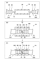
- FIG. 1 is an explanatory diagram illustrating the overall configuration of a guidewire 1A of the first embodiment.
- the guidewire 1A is a medical device used for treating blood vessels, etc.
- the guidewire 1A has a first core shaft 10, a second core shaft 20, a tubular member 30, and a coil 40.
- the first core shaft 10 is a long member that extends from the tip end to the rear end of the guidewire 1A. Details of the first core shaft 10 will be described later.
- the second core shaft 20 is a long member that is located rearward of the first core shaft 10 and is coaxial with the first core shaft 10. Details of the second core shaft 20 will be described later.
- the material of the first core shaft 10 and the second core shaft 20 is not particularly limited, but may be, for example, stainless steel (SUS302, SUS304, SUS316, etc.), superelastic alloys such as Ni-Ti alloys, piano wire, nickel-chromium alloys, cobalt alloys, platinum, gold, tungsten, etc.
- the first core shaft 10 and the second core shaft 20 are made of different materials.
- the first core shaft 10 and the second core shaft 20 may be made of the same material.
- the tubular member 30 is a hollow member that covers the outer periphery of the rear end portion 11 (FIG. 2) of the first core shaft 10 and the front end portion 21 (FIG. 2) of the second core shaft 20, and is joined to the first core shaft 10 and the second core shaft 20. Details of the tubular member 30 will be described later.
- the material of the tubular member 30 is not particularly limited, but examples that can be used include stainless steel (SUS302, SUS304, SUS316, etc.), superelastic alloys such as Ni-Ti alloys, piano wire, nickel-chromium alloys, cobalt alloys, platinum, gold, tungsten, etc.
- stainless steel SUS302, SUS304, SUS316, etc.
- superelastic alloys such as Ni-Ti alloys, piano wire, nickel-chromium alloys, cobalt alloys, platinum, gold, tungsten, etc.
- the coil 40 is a member that covers the tip end of the first core shaft 10 and is formed from a metal wire wound in a spiral shape around the outer circumference of the first core shaft 10.
- FIG. 2 is an explanatory diagram illustrating a longitudinal section of the tubular member 30 of the guidewire 1A of the first embodiment.
- the rear end 11 of the first core shaft 10 and the tip end 21 of the second core shaft 20 are disposed inside the tubular member 30.
- the inside of the tubular member 30 is filled with adhesive 100, and the tubular member 30, the first core shaft 10, and the second core shaft 20 are joined by the adhesive 100.
- the rear end portion 11 of the first core shaft 10 is arranged in the order of the first protrusion portion 50, the straight portion 13, the first protrusion portion 60, the straight portion 14, and the straight portion 15 from the rear end 12 of the first core shaft 10 toward the tip side.
- the first protrusion portions 50 and 60 are portions that protrude toward the radially outer side of the first core shaft 10 and have a relatively larger outer diameter than the straight portions 13 and 14.
- the maximum outer diameter of the first protrusion portions 50 and 60 is approximately the same as the maximum outer diameter of the straight portion 15.
- the straight portions 13, 14, and 15 are portions whose outer diameter is approximately constant in the long axis direction. A part of the straight portion 15 is arranged outside the tubular member 30. Details of the first protrusion portions 50 and 60 will be described later.
- the tip portion 21 of the second core shaft 20 is arranged in the following order from the tip portion 22 of the second core shaft 20 toward the rear end side: the second protrusion portion 70, the straight portion 23, the second protrusion portion 80, the straight portion 24, and the straight portion 25.
- the second protrusion portions 70, 80 protrude toward the radially outer side of the second core shaft 20 and have a relatively larger outer diameter than the straight portions 23, 24.
- the maximum outer diameter of the second protrusion portions 70, 80 is approximately the same as the maximum outer diameter of the straight portion 25.
- the straight portions 23, 24, 25 are portions whose outer diameter is approximately constant in the long axis direction. A part of the straight portion 25 is arranged outside the tubular member 30. Details of the second protrusion portion 70 and the second protrusion portion 80 will be described later.
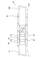
- Fig. 3 is an explanatory diagram illustrating an enlarged view of the first protrusions 50, 60 of the guidewire 1A of the first embodiment.
- Fig. 4 is an explanatory diagram illustrating a cross section of the tubular member 30 taken along line A-A in Fig. 2.
- the two first protrusions (50, 60) each have an apex (51, 61), a first tapered portion (52, 62), and a back surface (53, 63).
- the apex (51, 61) is formed at the end of the first protrusions (50, 60) in the protrusion direction (radial direction of the first core shaft 10) and engages with the inner peripheral portion 31 of the tubular member 30.
- the first tapered portion (52, 62) is formed at a portion of the side surface of the first protrusions (50, 60) closer to the rear end of the first core shaft 10 than the apex (51, 61).
- the angle between the first tapered portion (52, 62) and the straight portion (13, 14) is not particularly limited, but may be in the range of 5 degrees to 80 degrees.
- the first tapered portion (52, 62) extends from the apex (51, 61) toward the rear end side of the first core shaft 10, and has a shape in which the outer diameter decreases from the front end side to the rear end side of the first core shaft 10.
- the back surface (53, 63) is formed in the first protrusion portion (50, 60) at a position substantially identical to the apex (51, 61) in the axial direction of the first core shaft 10, or at a portion closer to the front end side of the first core shaft 10 than the apex (51, 61).
- the back surface (53, 63) extends substantially perpendicularly from the outer circumferential surface of the straight portion (13, 14) toward the outside in the radial direction.
- the angle between the back surface (53, 63) and the straight portion (13, 14) is substantially 90 degrees.
- a crest (51, 61) is formed at the intersection of the back surface (53, 63) and the first tapered portion (52, 62).
- the first protrusion (50, 60) has a triangular shape protruding toward the inner peripheral portion 31 of the tubular member 30.
- the inner peripheral portion 31 of the tubular member 30 is recessed along the shape of the crest (51, 61), and the recess and the crest (51, 61) are fitted together to engage the tubular member 30 and the first core shaft 10.
- the inner peripheral portion 31 of the tubular member 30 recessed along the shape of the crest 51 is referred to as the "engaged portion 33”
- the inner peripheral portion 31 of the tubular member 30 recessed along the shape of the crest 61 is referred to as the "engaged portion 34.”
- the first tapered portion 52 and the first tapered portion 62 are compared, the first tapered portion 62 has a gentler inclination and a smaller taper rate than the first tapered portion 52 .
- the first protrusion 50 is formed along the circumferential direction on the outer periphery of the first core shaft 10.
- the first protrusion 50 has a generally ring-shaped cross section.
- the annular apex 51 fits into and engages with the inner periphery 31 of the tubular member 30 along the circumferential direction.
- the first protrusion 60 is also formed along the circumferential direction on the outer periphery of the first core shaft 10.
- the outer peripheral portion 32 of the tubular member 30 is formed with two protrusions 35 and 36 that protrude radially outward from the tubular member 30.
- the protrusions (35, 36) have a larger outer diameter than the other portions of the tubular member 30 than the protrusions (35, 36).
- the protrusions (35, 36) bulge in a mountain shape on the outer peripheral portion 32 of the tubular member 30, and their surfaces are formed by curved surfaces.
- the protrusions (35, 36) are formed by the inner peripheral portion 31 of the tubular member 30 being pressed against the first protrusions (50, 60) of the first core shaft 10, thereby causing the outer peripheral portion 32 to bulge, by a manufacturing method described later. For this reason, the positions of the protrusions (35, 36) of the tubular member 30 and the first protrusions (50, 60) of the first core shaft 10 are substantially the same in the longitudinal direction.
- the protrusions 35 of the tubular member 30 are formed along the circumferential direction on the outer periphery of the tubular member 30.
- the protrusions 36 are also formed along the circumferential direction on the outer periphery of the tubular member 30.
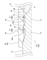
- FIG. 5 is an explanatory diagram illustrating an enlarged view of the second protrusions 70, 80 of the guide wire 1A of the first embodiment.
- Fig. 6 is a cross section taken along line B-B in Fig. 2, illustrating a cross section of the tubular member 30.
- the two second protrusions (70, 80) each have an apex (71, 81), a second tapered portion (72, 82), and a back surface (73, 83).
- the apex (71, 81) is formed at the end of the second protrusions (70, 80) in the protrusion direction (radial direction of the second core shaft 20) and engages with the inner periphery 31 of the tubular member 30.
- the second tapered portion (72, 82) is formed at a portion of the side surface of the second protrusions (70, 80) closer to the tip end of the second core shaft 20 than the apex (71, 81).
- the angle between the second tapered portion (72, 82) and the straight portion (23, 24) is not particularly limited, but may be in the range of 5 degrees to 80 degrees.
- the second tapered portion (72, 82) extends from the apex (71, 81) toward the tip side of the second core shaft 20, and has a shape in which the outer diameter decreases from the rear end side of the second core shaft 20 toward the tip side.
- the back surface (73, 83) is formed at a position of the second protrusion portion (70, 80) that is substantially the same as the apex (71, 81) in the axial direction of the second core shaft 20, or at a portion closer to the rear end side of the second core shaft 20 than the apex (71, 81).
- the back surface (73, 83) extends substantially perpendicularly from the outer circumferential surface of the straight portion (23, 24) toward the outside in the radial direction.
- the angle between the back surface (73, 83) and the straight portion (23, 24) is substantially 90 degrees.
- a crest (71, 81) is formed at the intersection of the back surface (73, 83) and the second tapered portion (72, 82).
- the second protrusion (70, 80) has a triangular shape protruding toward the inner peripheral portion 31 of the tubular member 30.
- the inner peripheral portion 31 of the tubular member 30 is recessed along the shape of the crest (71, 81), and the recess and the crest (71, 81) are fitted together to engage the tubular member 30 and the second core shaft 20.
- the inner peripheral portion 31 of the tubular member 30 recessed along the shape of the crest 71 is referred to as the "engaged portion 93”
- the inner peripheral portion 31 of the tubular member 30 recessed along the shape of the crest 81 is referred to as the "engaged portion 94.”
- the second tapered portion 82 has a gentler inclination and a smaller taper rate than the second tapered portion 72 .
- the second protrusion 70 is formed along the circumferential direction on the outer periphery of the second core shaft 20.
- the second protrusion 70 has a generally ring-shaped cross section.
- the annular apex 71 fits into and engages with the inner periphery 31 of the tubular member 30 along the circumferential direction.
- the second protrusion 80 is also formed along the circumferential direction on the outer periphery of the second core shaft 20.
- the outer circumferential portion 32 of the tubular member 30 is formed with two protrusions 95 and 96 that protrude radially outward from the tubular member 30.
- the protrusions (95, 96) have a larger outer diameter than the other portions of the tubular member 30 than the protrusions (95, 96).
- the protrusions (95, 96) are formed in a mountain-like shape on the outer circumferential portion 32 of the tubular member 30, and their surfaces are formed by curved surfaces.
- the protrusions (95, 96) are formed by the inner circumferential portion 31 of the tubular member 30 being pressed by the second protrusions (70, 80) of the second core shaft 20, thereby causing the outer circumferential portion 32 to protrude, by a manufacturing method described later. Therefore, the positions of the protrusions (95, 96) of the tubular member 30 and the second protrusions (70, 80) of the second core shaft 20 in the long axis direction are substantially the same.
- the protrusion 95 of the tubular member 30 is formed along the circumferential direction on the outer periphery of the tubular member 30.
- the protrusion 96 is also formed along the circumferential direction on the outer periphery of the tubular member 30.
- ⁇ Joining method> 7 is an explanatory diagram illustrating a method of joining the first core shaft 10, the second core shaft 20, and the tubular member 30.
- a tubular member 30 having an inner diameter smaller than the outer diameter of the rear end portion 11 of the first core shaft 10 and the outer diameter of the tip portion 21 of the second core shaft 20 at room temperature is prepared.
- the tubular member 30 is heated, and the inner diameter of the tubular member 30 is made larger than the outer diameter of the rear end portion 11 of the first core shaft 10 and the outer diameter of the tip portion 21 of the second core shaft 20 by utilizing thermal expansion.
- the tubular member 30 is cooled to return the tubular member 30 to its shape before heating, so that the first protrusions (50, 60) of the first core shaft 10 and the second protrusions (70, 80) of the second core shaft 20 enter and engage with the inner peripheral portion 31 of the tubular member 30.
- the first protrusions (50, 60) engage with the tubular member 30, thereby preventing the first core shaft 10 from coming off the tubular member 30, and improving the joining strength between the first core shaft 10 and the tubular member 30. Furthermore, when a force is applied to the first core shaft 10 in a direction to pull it out toward the tip side, the back surface (53, 63) engages with the wall surface of the engaged portion (33, 34) to generate resistance, so that the first core shaft 10 can be more reliably prevented from coming off.
- first tapered portion (52, 62) narrows the axial width of the first protrusions (50, 60) toward the height direction, thereby narrowing the shape of the apex (51, 61), and making it easier for the apex (51, 61) to engage with the inner peripheral portion 31 of the tubular member 30. Furthermore, the first tapered portion (52, 62) makes it easier to insert the first core shaft 10 into the tubular member 30 during manufacturing.
- the second protrusions (70, 80) engage with the tubular member 30, thereby preventing the second core shaft 20 from coming off the tubular member 30, and improving the joining strength between the second core shaft 20 and the tubular member 30. Furthermore, when a force is applied to the second core shaft 20 in a direction that causes it to come off toward the base end, the back surface (73, 83) engages with the wall surface of the engaged portion (93, 94) to generate resistance, so that the second core shaft 20 can be more reliably prevented from coming off.
- the second tapered portion (72, 82) narrows the axial width of the second protrusions (70, 80) toward the height direction, thereby narrowing the shape of the top portion (71, 81), and making it easier for the top portion (71, 81) to engage with the inner periphery 31 of the tubular member 30. Furthermore, the second tapered portion (72, 82) makes it easier to insert the second core shaft 20 into the tubular member 30 during manufacturing.
- the first protrusions (50, 60) and the second protrusions (70, 80) are provided along the circumferential direction of the inner periphery 31 of the tubular member 30. This allows the apexes (51, 61) and apexes (71, 81) to engage along the entire circumferential direction, more reliably preventing the first core shaft 10 and the second core shaft 20 from coming loose.
- the tubular member 30 has protrusions (35, 36, 95, 96) on the outer periphery 32. This reduces the contact area between the guidewire 1A and the tubular member 30 and the medical device (not shown) or the body wall used in conjunction with the guidewire 1A, improving the sliding properties of the guidewire 1A.
- FIG. 8 is an explanatory diagram illustrating a longitudinal section of a tubular member 30Z of a conventional guidewire 1Z.
- the guidewire 1Z differs from the guidewire 1A in that the guidewire 1Z does not have a first protrusion (50, 60) at the rear end 11Z of the first core shaft 10Z, and does not have a second protrusion (70, 80) at the tip 21Z of the second core shaft 20Z.
- the inner diameter of the tubular member 30Z at room temperature is larger than the outer diameter of the rear end 11Z of the first core shaft 10Z and the outer diameter of the tip 21Z of the second core shaft 20Z.
- the first core shaft 10Z and the tubular member 30Z, and the second core shaft 20Z and the tubular member 30Z are connected to each other only by the adhesive force of the adhesive 100. That is, in the guidewire 1Z, the first core shaft 10Z and the second core shaft 20Z are not engaged with the tubular member 30Z, so there is a high possibility that the first core shaft 10Z and the second core shaft 20Z will come off the tubular member 30Z.
- the first core shaft 10 and the second core shaft 20 are engaged with the inner periphery of the tubular member 30 via the first and second protrusions (50, 60, 70, 80), so the possibility that the first core shaft 10 and the second core shaft 20 will come off the tubular member 30 can be reduced.
- the outer periphery 32Z of the tubular member 30Z is flat in the axial direction, so that the slidability with other medical devices and the body wall may decrease.
- the protrusions 35, 36, 95, 96
- the protrusions are formed on the outer periphery 32 of the tubular member 30, so that the decrease in slidability can be suppressed.
- Second Embodiment 9 is an explanatory diagram illustrating a longitudinal cross section of the tubular member 30 of the guidewire 1B of the second embodiment.
- the guidewire 1B of the second embodiment is different from the guidewire 1A of the first embodiment in that the second core shaft 20B does not have the second protrusions (70, 80).
- a description of the configuration of the guidewire 1B that is common to the guidewire 1A will be omitted.
- the first core shaft 10 has the first protrusions (50, 60), which prevents the first core shaft 10 from coming out of the tubular member 30 and improves the bonding strength between the first core shaft 10 and the tubular member 30.
- Third Embodiment 10 is an explanatory diagram illustrating a longitudinal cross section of a tubular member 30 of a guidewire 1C of the third embodiment.
- the guidewire 1C of the third embodiment is different from the guidewire 1A of the first embodiment in that the first protrusions (50C, 60C) and the second protrusions (70C, 80C) are not provided along the circumferential direction.
- a description of the configuration of the guidewire 1C that is common to the guidewire 1A will be omitted.
- the first protrusion 50C is provided on a portion of the outer periphery of the first core shaft 10C in the circumferential direction.
- two first protrusions 50C are provided in the circumferential direction, and each first protrusion 50C is provided 180° opposite in the circumferential direction.
- the apex 51C engages with a portion of the inner periphery 31 of the tubular member 30 in the circumferential direction.
- the first protrusion 60C is also provided on a portion of the outer periphery of the first core shaft 10C in the circumferential direction.
- two first protrusions (50C, 60C) are provided in the circumferential direction, but three or more first protrusions (50C, 60C) may be provided in the circumferential direction.
- the second protrusions (70C, 80C) are also provided on a portion of the circumferential outer periphery of the second core shaft 20C, similar to the first protrusions (50C, 60C).
- the first core shaft 10C has the first protrusions (50C, 60C) and the second core shaft 20C has the second protrusions (70C, 80C), which prevents the first core shaft 10C and the second core shaft 20C from coming out of the tubular member 30 and improves the bonding strength between the first core shaft 10C, the second core shaft 20C, and the tubular member 30.
- Fourth Embodiment 12 is an explanatory diagram illustrating an enlarged view of the first protrusions (50D, 60D) of the guidewire 1D of the fourth embodiment.
- the guidewire 1D of the fourth embodiment is different from the guidewire 1A of the first embodiment in that the back surface (53D, 63D) is inclined toward the tip side with respect to the outer circumferential surface of the first core shaft 10D. That is, the angle between the back surface (53D, 63D) and the straight portion (13, 14) is 90 degrees or more.
- a description of the configuration of the guidewire 1D that is common to the guidewire 1A will be omitted.
- the guidewire 1D of this embodiment also has the first protrusions (50D, 60D) on the first core shaft 10D, which prevents the first core shaft 10D from coming out of the tubular member 30, thereby improving the bonding strength between the first core shaft 10D and the tubular member 30.
- Fifth Embodiment 13 is an explanatory diagram illustrating an enlarged view of the first protrusions (50E, 60E) of the guidewire 1E of the fifth embodiment.
- the guidewire 1E of the fifth embodiment is different from the guidewire 1A of the first embodiment in that the back surface (53E, 63E) is inclined toward the rear end side with respect to the outer circumferential surface of the first core shaft 10. That is, the angle between the back surface (53E, 63E) and the straight portion (13, 14) is smaller than 90 degrees.
- a description of the configuration of the guidewire 1E that is common to the guidewire 1A will be omitted.
- the guidewire 1E of this embodiment also has the first protrusions (50E, 60E) in the first core shaft 10E, which prevents the first core shaft 10E from coming out of the tubular member 30, thereby improving the bonding strength between the first core shaft 10E and the tubular member 30.
- the apexes (51, 61, 71, 81) are triangular, but they do not have to be triangular. For example, they may be square, rectangular, circular, or the like.
- the first tapered portion (52, 62) and the second tapered portion (72, 82) are formed at a constant taper rate in the longitudinal direction of the guidewire (1A, 1B, 1C, 1D, 1E), but they do not have to be formed at a constant taper rate.
- the taper rate of the first tapered portion (52, 62) and the second tapered portion (72, 82) may vary in the longitudinal direction, or may be formed in a stepped shape.
- the protrusions (35, 36, 95, 96) of the tubular member 30 are formed along the circumferential direction on the outer periphery of the tubular member 30, but they do not have to be formed along the circumferential direction on the outer periphery of the tubular member 30.
- they may be formed on a part of the outer periphery of the tubular member 30 in the circumferential direction, or a plurality of hemispherical protrusions (35, 36, 95, 96) may be formed on the outer periphery of the tubular member 30.
Landscapes
- Health & Medical Sciences (AREA)
- Life Sciences & Earth Sciences (AREA)
- Biophysics (AREA)
- Pulmonology (AREA)
- Engineering & Computer Science (AREA)
- Anesthesiology (AREA)
- Biomedical Technology (AREA)
- Heart & Thoracic Surgery (AREA)
- Hematology (AREA)
- Animal Behavior & Ethology (AREA)
- General Health & Medical Sciences (AREA)
- Public Health (AREA)
- Veterinary Medicine (AREA)
- Media Introduction/Drainage Providing Device (AREA)
- Flexible Shafts (AREA)
Applications Claiming Priority (2)
| Application Number | Priority Date | Filing Date | Title |
|---|---|---|---|
| JP2023-002072 | 2023-01-11 | ||
| JP2023002072A JP2024098536A (ja) | 2023-01-11 | 2023-01-11 | ガイドワイヤ |
Publications (1)
| Publication Number | Publication Date |
|---|---|
| WO2024150540A1 true WO2024150540A1 (ja) | 2024-07-18 |
Family
ID=91896679
Family Applications (1)
| Application Number | Title | Priority Date | Filing Date |
|---|---|---|---|
| PCT/JP2023/041713 Ceased WO2024150540A1 (ja) | 2023-01-11 | 2023-11-21 | ガイドワイヤ |
Country Status (2)
| Country | Link |
|---|---|
| JP (1) | JP2024098536A (https=) |
| WO (1) | WO2024150540A1 (https=) |
Citations (4)
| Publication number | Priority date | Publication date | Assignee | Title |
|---|---|---|---|---|
| JPH024390A (ja) * | 1987-12-23 | 1990-01-09 | Advanced Cardeovascular Syst Inc | 心血管治療用延長可能ガイドワイヤシステム |
| JPH08506261A (ja) * | 1993-05-14 | 1996-07-09 | シュナイダー(ユーエスエー)インク | 交換可能なガイドワイヤ |
| JPH09182798A (ja) * | 1995-12-28 | 1997-07-15 | Asahi Intec Kk | ガイドワイヤ |
| JP2011194070A (ja) * | 2010-03-19 | 2011-10-06 | Terumo Corp | 延長ワイヤ |
-
2023
- 2023-01-11 JP JP2023002072A patent/JP2024098536A/ja active Pending
- 2023-11-21 WO PCT/JP2023/041713 patent/WO2024150540A1/ja not_active Ceased
Patent Citations (4)
| Publication number | Priority date | Publication date | Assignee | Title |
|---|---|---|---|---|
| JPH024390A (ja) * | 1987-12-23 | 1990-01-09 | Advanced Cardeovascular Syst Inc | 心血管治療用延長可能ガイドワイヤシステム |
| JPH08506261A (ja) * | 1993-05-14 | 1996-07-09 | シュナイダー(ユーエスエー)インク | 交換可能なガイドワイヤ |
| JPH09182798A (ja) * | 1995-12-28 | 1997-07-15 | Asahi Intec Kk | ガイドワイヤ |
| JP2011194070A (ja) * | 2010-03-19 | 2011-10-06 | Terumo Corp | 延長ワイヤ |
Also Published As
| Publication number | Publication date |
|---|---|
| JP2024098536A (ja) | 2024-07-24 |
Similar Documents
| Publication | Publication Date | Title |
|---|---|---|
| US8608670B2 (en) | Guidewire | |
| US5673707A (en) | Enhanced performance guidewire | |
| CN104602616B (zh) | 导向工具 | |
| US7547288B2 (en) | Guide wire | |
| US8043232B2 (en) | High performance wire guide | |
| JP4494782B2 (ja) | 複合ガイドワイヤ | |
| US20070244413A1 (en) | Medical guidewire tip construction | |
| US7722551B2 (en) | Guide wire | |
| JP2009183765A (ja) | 複合ガイドワイヤ | |
| US20210322730A1 (en) | Guidewire having bonded proximal and distal segments | |
| JP7684276B2 (ja) | 高周波処置具 | |
| US10039903B2 (en) | Wire guide and method of making the same | |
| JP2011206174A (ja) | ガイドワイヤ | |
| WO2024150540A1 (ja) | ガイドワイヤ | |
| WO2022158418A1 (ja) | カテーテル | |
| JP4783343B2 (ja) | ガイドワイヤ | |
| JP2003299739A (ja) | 医療用ガイドワイヤ | |
| JP7532573B2 (ja) | ガイドワイヤ | |
| WO2019146086A1 (ja) | カテーテル | |
| JP5328835B2 (ja) | ガイドワイヤの製造方法 | |
| JP3962652B2 (ja) | ガイドワイヤ | |
| US20250295892A1 (en) | Guide wire | |
| WO2024236759A1 (ja) | 血管用ガイドワイヤ | |
| JP2025020797A (ja) | ガイドワイヤ | |
| JP2004065794A (ja) | ガイドワイヤ |
Legal Events
| Date | Code | Title | Description |
|---|---|---|---|
| 121 | Ep: the epo has been informed by wipo that ep was designated in this application |
Ref document number: 23916157 Country of ref document: EP Kind code of ref document: A1 |
|
| NENP | Non-entry into the national phase |
Ref country code: DE |
|
| 122 | Ep: pct application non-entry in european phase |
Ref document number: 23916157 Country of ref document: EP Kind code of ref document: A1 |