WO2024147268A1 - 光学系、光学機器、交換レンズおよび光学系の製造方法 - Google Patents
光学系、光学機器、交換レンズおよび光学系の製造方法 Download PDFInfo
- Publication number
- WO2024147268A1 WO2024147268A1 PCT/JP2023/044790 JP2023044790W WO2024147268A1 WO 2024147268 A1 WO2024147268 A1 WO 2024147268A1 JP 2023044790 W JP2023044790 W JP 2023044790W WO 2024147268 A1 WO2024147268 A1 WO 2024147268A1
- Authority
- WO
- WIPO (PCT)
- Prior art keywords
- lens
- optical system
- group
- focusing
- object side
- Prior art date
- Legal status (The legal status is an assumption and is not a legal conclusion. Google has not performed a legal analysis and makes no representation as to the accuracy of the status listed.)
- Ceased
Links
Images

Classifications
-
- G—PHYSICS
- G02—OPTICS
- G02B—OPTICAL ELEMENTS, SYSTEMS OR APPARATUS
- G02B9/00—Optical objectives characterised both by the number of the components and their arrangements according to their sign, i.e. + or -
- G02B9/04—Optical objectives characterised both by the number of the components and their arrangements according to their sign, i.e. + or - having two components only
- G02B9/10—Optical objectives characterised both by the number of the components and their arrangements according to their sign, i.e. + or - having two components only one + and one - component
-
- G—PHYSICS
- G02—OPTICS
- G02B—OPTICAL ELEMENTS, SYSTEMS OR APPARATUS
- G02B13/00—Optical objectives specially designed for the purposes specified below
-
- G—PHYSICS
- G02—OPTICS
- G02B—OPTICAL ELEMENTS, SYSTEMS OR APPARATUS
- G02B13/00—Optical objectives specially designed for the purposes specified below
- G02B13/18—Optical objectives specially designed for the purposes specified below with lenses having one or more non-spherical faces, e.g. for reducing geometrical aberration
-
- G—PHYSICS
- G02—OPTICS
- G02B—OPTICAL ELEMENTS, SYSTEMS OR APPARATUS
- G02B15/00—Optical objectives with means for varying the magnification
- G02B15/14—Optical objectives with means for varying the magnification by axial movement of one or more lenses or groups of lenses relative to the image plane for continuously varying the equivalent focal length of the objective
- G02B15/16—Optical objectives with means for varying the magnification by axial movement of one or more lenses or groups of lenses relative to the image plane for continuously varying the equivalent focal length of the objective with interdependent non-linearly related movements between one lens or lens group, and another lens or lens group
- G02B15/20—Optical objectives with means for varying the magnification by axial movement of one or more lenses or groups of lenses relative to the image plane for continuously varying the equivalent focal length of the objective with interdependent non-linearly related movements between one lens or lens group, and another lens or lens group having an additional movable lens or lens group for varying the objective focal length
-
- G—PHYSICS
- G02—OPTICS
- G02B—OPTICAL ELEMENTS, SYSTEMS OR APPARATUS
- G02B3/00—Simple or compound lenses
- G02B3/0006—Arrays
- G02B3/0037—Arrays characterized by the distribution or form of lenses
- G02B3/0043—Inhomogeneous or irregular arrays, e.g. varying shape, size, height
-
- G—PHYSICS
- G02—OPTICS
- G02B—OPTICAL ELEMENTS, SYSTEMS OR APPARATUS
- G02B3/00—Simple or compound lenses
- G02B3/02—Simple or compound lenses with non-spherical faces
- G02B3/04—Simple or compound lenses with non-spherical faces with continuous faces that are rotationally symmetrical but deviate from a true sphere, e.g. so called "aspheric" lenses
-
- G—PHYSICS
- G02—OPTICS
- G02B—OPTICAL ELEMENTS, SYSTEMS OR APPARATUS
- G02B9/00—Optical objectives characterised both by the number of the components and their arrangements according to their sign, i.e. + or -
- G02B9/64—Optical objectives characterised both by the number of the components and their arrangements according to their sign, i.e. + or - having more than six components
-
- H—ELECTRICITY
- H04—ELECTRIC COMMUNICATION TECHNIQUE
- H04N—PICTORIAL COMMUNICATION, e.g. TELEVISION
- H04N23/00—Cameras or camera modules comprising electronic image sensors; Control thereof
- H04N23/50—Constructional details
- H04N23/55—Optical parts specially adapted for electronic image sensors; Mounting thereof
Definitions
- This disclosure relates to optical systems, optical instruments, interchangeable lenses, and methods for manufacturing optical systems.
- optical systems have been proposed for use in optical devices such as photo cameras, electronic still cameras, and video cameras (see, for example, Patent Document 1).
- the optical system of the present disclosure has, in order from the object side, a front group having positive refractive power, an aperture stop, and a rear group, and satisfies all of the following conditional expressions. 0.10 ⁇ ff/
- FIG. 2 is a cross-sectional view of the optical system of the first embodiment when focusing on an object at infinity.
- 3A to 3C are diagrams showing various aberrations in the optical system of the first example.
- FIG. 11 is a cross-sectional view of the optical system of the second embodiment when focusing on an object at infinity.
- 13A to 13C are diagrams showing various aberrations in the optical system of the second embodiment.
- FIG. 13 is a cross-sectional view of the optical system of the third embodiment when focusing on an object at infinity.
- 13A to 13C are diagrams showing various aberrations in the optical system of the third embodiment.
- FIG. 13 is a cross-sectional view of the optical system of the fourth embodiment when focusing on an object at infinity.
- FIG. 13A to 13C are diagrams showing various aberrations in the optical system of the fourth example.
- FIG. 13 is a cross-sectional view of the optical system of the fifth embodiment when focusing on an object at infinity.
- 13A to 13C are diagrams showing various aberrations in the optical system of the fifth embodiment.
- FIG. 13 is a cross-sectional view of the optical system of Example 6 when focusing on an object at infinity.
- 13A to 13C are diagrams showing various aberrations in the optical system of the sixth embodiment.
- FIG. 13 is a cross-sectional view of the optical system of the seventh embodiment when focusing on an object at infinity.
- 13A to 13C are diagrams showing various aberrations in the optical system of the seventh example.
- FIG. 13 is a cross-sectional view of the optical system of the eighth embodiment when focusing on an object at infinity.
- 13A to 13C are diagrams showing various aberrations in the optical system of the eighth example.
- FIG. 13 is a cross-sectional view of the optical system of the ninth embodiment when focusing on an object at infinity.
- 13A to 13C are diagrams showing various aberrations in the optical system of the ninth example.
- FIG. 23 is a cross-sectional view of the optical system of the tenth embodiment when focusing on an object at infinity.
- 16A to 16C are diagrams showing various aberrations in the optical system of the tenth example.
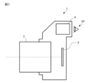
- FIG. 1 is a schematic diagram of a camera equipped with the optical system of the present embodiment. 1 is a flowchart outlining a method for manufacturing an optical system according to the present embodiment.
- the optical system of this embodiment has, in order from the object side, a front group having positive refractive power, an aperture stop, and a rear group, and satisfies all of the following conditional expressions.
- (1) 0.10 ⁇ ff /
- (2) 0.13 ⁇ tr / TL ⁇ 0.45
- the front group has positive refractive power, so the principal point can be located on the object side, making it possible to shorten the overall length relative to the focal length.
- the effect of this embodiment can be made more certain by setting the lower limit of conditional expression (1) to 0.10. In order to make the effect of this embodiment more certain, it is preferable to set the lower limit of conditional expression (1) to 0.15, 0.19, or even 0.40.
- Conditional formula (2) defines the ratio between the sum of the center thicknesses of the lenses in the rear group and the overall length of the optical system.
- conditional expression (3) if the value of conditional expression (3) exceeds the upper limit, it becomes difficult to appropriately correct various aberrations, including spherical aberration, coma, field curvature, and distortion.
- conditional expression (3) falls below the lower limit, the overall length of the optical system becomes long, and the optical system becomes large.
- the effect of this embodiment can be made more certain by setting the upper limit value of conditional expression (4) to 0.70. In order to make the effect of this embodiment more certain, it is preferable to set the upper limit value of conditional expression (4) to 0.65, 0.60, or even 0.40.
- Conditional formula (5) defines the ratio between the focal length of the single lens Pfoi and the focal length of the rear group.
- conditional expression (5) falls below the lower limit, the refractive power of the single lens Pfoi becomes too strong, making it difficult to properly correct various aberrations, including spherical aberration, coma, and curvature of field.
- the effect of this embodiment can be made more certain by setting the upper limit value of conditional expression (6) to 0.55. In order to make the effect of this embodiment more certain, it is preferable to set the upper limit value of conditional expression (6) to 0.50, 0.48, 0.46, or even 0.40.
- the effect of this embodiment can be made more certain by setting the lower limit of conditional expression (6) to 0.25. In order to make the effect of this embodiment more certain, it is preferable to set the lower limit of conditional expression (6) to 0.28, 0.30, or even 0.31.
- Conditional formula (7) specifies the ratio between the distance on the optical axis between the object-side lens surface of lens Li1 and the image-side lens surface of lens Li2 when focusing at infinity and the back focus in the air-equivalent length of the optical system.
- conditional formula (7) specifies the ratio between the distance on the optical axis between the object-side lens surface of lens Li1 and the image-side lens surface of lens Li2 when focusing at infinity and the back focus in the air-equivalent length of the optical system.
- conditional expression (7) if the value of conditional expression (7) exceeds the upper limit, it becomes difficult to appropriately correct the field curvature and coma aberration.
- the effect of this embodiment can be made more certain by setting the upper limit value of conditional expression (7) to 1.10. In order to make the effect of this embodiment more certain, it is preferable to set the upper limit value of conditional expression (7) to 1.05, and further to 1.00.
- conditional expression (7) falls below the lower limit, it becomes difficult to appropriately correct the field curvature and distortion.
- the effect of this embodiment can be made more certain by setting the lower limit of conditional expression (7) to 0.05. In order to make the effect of this embodiment more certain, it is preferable to set the lower limit of conditional expression (7) to 0.06, or even 0.07.
- the rear group has a plurality of lens groups including at least one focusing group that moves during focusing, and that the spacing between the plurality of lens groups changes during focusing, and that the following conditional expression is satisfied: (8) 0.30 ⁇ tGi / Da ⁇ 9.00 however, tGi: the sum of the lengths on the optical axis of the lenses included in the lens group Gi that is located closest to the image side among the multiple lens groups
- Conditional formula (8) specifies the ratio between the sum of the axial lengths of the lenses included in lens group Gi and the axial distance between the object-side lens surface of lens Li1 and the image-side lens surface of lens Li2 when focusing at infinity.
- conditional expression (8) in the optical system of this embodiment exceeds the upper limit, the lens thickness of the lens group Gi becomes too large, and the weight of the optical system increases.
- the effect of this embodiment can be made more certain by setting the upper limit value of conditional expression (8) to 9.00. In order to make the effect of this embodiment more certain, it is preferable to set the upper limit value of conditional expression (8) to 8.50, 8.00, 7.80, 7.60, or even 3.00.
- conditional expression (8) falls below the lower limit, it becomes difficult to appropriately correct various aberrations, including curvature of field and distortion.
- the effect of this embodiment can be made more certain by setting the lower limit of conditional expression (8) to 0.30. In order to make the effect of this embodiment more certain, it is preferable to set the lower limit of conditional expression (8) to 0.32, 0.34, 0.60, 1.00, or even 1.50.
- the optical system of this embodiment satisfies the following conditional expression. (9) 0.40 ⁇ D1/TL ⁇ 0.85 however, D1: The distance on the optical axis between the lens surface closest to the object and the object-side surface of the single lens Pr having the strongest refractive power among the biconvex single lenses in the rear group when focusing at infinity
- Conditional expression (9) specifies the ratio of the distance on the optical axis when focusing at infinity between the lens surface closest to the object and the lens surface closest to the object of the single lens Pr to the total length of the optical system.
- conditional expression (9) the optical system of this embodiment can appropriately correct various aberrations, including spherical aberration, coma, curvature of field, and distortion, while preventing the optical system from becoming too large.
- conditional expression (9) if the value of conditional expression (9) exceeds the upper limit, the refractive power between the lens surface closest to the object and the lens surface of the single lens Pr closest to the object becomes too weak, the lens diameter increases, and the optical system becomes large.
- the effect of this embodiment can be made more certain by setting the upper limit value of conditional expression (9) to 0.85. In order to make the effect of this embodiment more certain, it is preferable to set the upper limit value of conditional expression (9) to 0.84, 0.82, or even 0.80.
- conditional expression (9) falls below the lower limit, the refractive power between the lens surface closest to the object and the lens surface of the single lens Pr closest to the object becomes too strong, causing high-order spherical aberration, coma, curvature of field, and distortion, making it difficult to properly correct the various aberrations.
- the effect of this embodiment can be made more certain by setting the lower limit of conditional expression (9) to 0.40. In order to make the effect of this embodiment more certain, it is preferable to set the lower limit of conditional expression (9) to 0.45, or even 0.50.
- the optical system of this embodiment satisfies the following conditional expression. (10) 0.10 ⁇ D2/TL ⁇ 0.80 however, D2: The distance on the optical axis between the aperture stop and the object-side lens surface of the single lens Pr having the strongest refractive power among the biconvex single lenses in the rear group.
- Conditional formula (10) defines the ratio of the distance on the optical axis between the aperture stop and the object-side lens surface of the single lens Pr to the overall length of the optical system.
- conditional formula (10) the optical system of this embodiment can appropriately correct various aberrations, including spherical aberration, coma, curvature of field, and distortion, while preventing the optical system from becoming too large.
- conditional expression (10) if the value of conditional expression (10) exceeds the upper limit, the refractive power between the aperture stop and the object-side lens surface of the single lens Pr becomes too weak, the lens diameter increases, and the optical system becomes large.
- the effect of this embodiment can be made more certain by setting the upper limit value of conditional expression (10) to 0.80. In order to make the effect of this embodiment more certain, it is preferable to set the upper limit value of conditional expression (10) to 0.70, 0.60, 0.50, 0.40, or even 0.36.
- conditional formula (10) falls below the lower limit, the refractive power between the aperture stop and the object-side lens surface of the single lens Pr becomes too strong, causing high-order spherical aberration, coma, field curvature, and distortion, making it difficult to properly correct the various aberrations.
- the effect of this embodiment can be made more certain by setting the lower limit of conditional expression (10) to 0.10. In order to make the effect of this embodiment more certain, it is preferable to set the lower limit of conditional expression (10) to 0.11, 0.12, or even 0.13.
- the optical system of this embodiment has at least one focusing group that moves during focusing, and satisfies the following conditional expression. (11) 0.25 ⁇
- Conditional expression (11) specifies the ratio between the focal length of the focusing group Gfo arranged closest to the object and the focal length of the optical system.
- conditional expression (11) the optical system of this embodiment can appropriately correct various aberrations, including spherical aberration, coma, curvature of field, and distortion, while suppressing an increase in the overall length of the optical system.
- conditional expression (11) if the value of conditional expression (11) exceeds the upper limit, it becomes difficult to suppress fluctuations in various aberrations, including spherical aberration, coma, field curvature, and distortion, during focusing.
- the effect of this embodiment can be made more certain by setting the upper limit value of conditional expression (11) to 0.90. In order to make the effect of this embodiment more certain, it is preferable to set the upper limit value of conditional expression (11) to 0.85, and more preferably 0.80.
- conditional expression (11) falls below the lower limit, the refractive power of the focusing group located closest to the object becomes too weak, and the amount of movement of the focusing group during focusing increases, increasing the overall length of the optical system.
- the effect of this embodiment can be made more certain by setting the lower limit of conditional expression (11) to 0.25. In order to make the effect of this embodiment more certain, it is preferable to set the lower limit of conditional expression (11) to 0.26, 0.28, 0.30, 0.31, or even 0.32.
- the front group has at least one positive lens Pf that satisfies both of the following conditional expressions: (12) 1.60 ⁇ n.d.Pf (13) ⁇ dPf ⁇ 31.00 (14) 0.01 ⁇ ⁇ gFPf - (0.6415 - 0.00162 ⁇ ⁇ dPf) however, ndPf: refractive index of the positive lens Pf for the d-line ⁇ dPf: Abbe number of the positive lens Pf based on the d-line ⁇ gFPf: partial dispersion ratio of the positive lens Pf, which is defined by the following equation when the refractive index of the positive lens Pf for the g-line is ngPf, the refractive index of the positive lens Pf for the F-line is nFPf, and the refractive index of the positive lens Pf for the C-line is nCPf.
- ⁇ gFPf (ngPf-nFPf) / (nFPf
- the optical system of this embodiment has at least one positive lens Pf in the front group, making it possible to appropriately correct various aberrations, including axial chromatic aberration.
- the optical system of this embodiment can suppress the occurrence of high-order aberrations by making the value of conditional expression (12) for the positive lens Pf greater than the lower limit.
- the effect of this embodiment can be made more certain by setting the lower limit of conditional expression (12) to 1.60. In order to make the effect of this embodiment more certain, it is preferable to set the lower limit of conditional expression (12) to 1.62, 1.64, or even 1.66.
- the optical system of this embodiment can effectively correct the secondary dispersion of axial chromatic aberration by making the value of conditional expression (13) for the positive lens Pf smaller than the upper limit.
- the effect of this embodiment can be made more certain by setting the upper limit value of conditional expression (13) to 31.00. In order to make the effect of this embodiment more certain, it is preferable to set the upper limit value of conditional expression (13) to 29.50, 28.00, or even 27.50.
- the optical system of this embodiment can effectively correct the secondary dispersion of axial chromatic aberration by making the value of conditional expression (14) for the positive lens Pf greater than the lower limit.
- the effect of this embodiment can be made more certain by setting the lower limit of conditional expression (14) to 0.01. In order to make the effect of this embodiment more certain, it is preferable to set the lower limit of conditional expression (14) to 0.015, 0.02, or even 0.025.
- the front group has at least one negative lens Nf that satisfies both of the following conditional expressions: (15) 1.85 ⁇ ndNf (16) ⁇ dNf ⁇ 26.00 (17) ⁇ gFNf-(0.6415-0.00162 ⁇ dNf) ⁇ 0.015 however, ndNf: refractive index of the negative lens Nf for the d line ⁇ dNf: Abbe number of the negative lens Nf based on the d line ⁇ gFNf: partial dispersion ratio of the negative lens Nf, which is defined by the following equation when the refractive index of the negative lens Nf for the g line is ngNf, the refractive index of the negative lens Nf for the F line is nFNf, and the refractive index of the negative lens Nf for the C line is nCNf.
- ⁇ gFNf (ngNf-nFNf)/(nFNf-nCNf)
- the optical system of this embodiment has at least one negative lens Nf in the front group, making it possible to appropriately correct various aberrations, including axial chromatic aberration.
- the optical system of this embodiment can suppress the occurrence of high-order aberrations by making the value of conditional expression (15) for the negative lens Nf greater than the lower limit.
- the effect of this embodiment can be made more certain by setting the lower limit of conditional expression (15) to 1.85.
- the optical system of this embodiment can effectively correct the secondary dispersion of axial chromatic aberration by making the value of conditional expression (16) for the negative lens Nf smaller than the upper limit.
- the effect of this embodiment can be made more certain by setting the upper limit value of conditional expression (16) to 26.00. In order to make the effect of this embodiment more certain, it is preferable to set the upper limit value of conditional expression (16) to 25.80, 25.50, or even 25.20.
- the optical system of this embodiment can effectively correct the secondary dispersion of axial chromatic aberration by making the value of conditional expression (17) for the negative lens Nf smaller than the upper limit.
- the effect of this embodiment can be made more certain by setting the upper limit value of conditional expression (17) to 0.015. In order to make the effect of this embodiment more certain, it is preferable to set the upper limit value of conditional expression (17) to 0.013, 0.012, or even 0.01.
- the above configuration makes it possible to realize an optical system that is compact and has good optical performance.
- the optical device of this embodiment is equipped with an optical system having the above-described configuration. This makes it possible to realize an optical device that is small and has good optical performance.
- the interchangeable lens of this embodiment has an optical system with the above-mentioned configuration. This makes it possible to realize an interchangeable lens that is small and has good optical performance.
- a method for manufacturing the optical system of the present embodiment includes constructing an optical system having, in order from the object side, a front group having positive refractive power, an aperture stop, and a rear group, so as to satisfy all of the following conditional expressions: (1) 0.10 ⁇ ff /
- This method of manufacturing an optical system makes it possible to manufacture an optical system that is small and has good optical performance.
- FIG. 1 is a cross-sectional view of the optical system of the first embodiment when focused on an object at infinity.
- the optical system of this embodiment has, from the object side, a first lens group G1 with positive refractive power, a second lens group G2 with negative refractive power, a third lens group G3 with positive refractive power, a fourth lens group G4 with positive refractive power, and a fifth lens group G5 with negative refractive power.
- the first lens group G1 consists of, in order from the object side, a meniscus-shaped positive lens L1 with its convex surface facing the object side, a meniscus-shaped positive lens L2 with its convex surface facing the object side, a meniscus-shaped positive lens L3 with its convex surface facing the object side, a cemented negative lens consisting of a biconvex positive lens L4 and a biconcave negative lens L5, an aperture stop S, and a meniscus-shaped positive lens L6 with its convex surface facing the object side.
- the second lens group G2 consists of a negative meniscus lens L7 with its convex surface facing the object side.
- the third lens group G3 consists of, in order from the object side, a meniscus-shaped positive lens L8 with its concave surface facing the object side, a cemented negative lens consisting of a biconcave negative lens L9 and a meniscus-shaped positive lens L10 with its convex surface facing the object side, a biconvex positive lens L11, and a meniscus-shaped negative lens L12 with its convex surface facing the object side.
- the fourth lens group G4 consists of a positive meniscus lens L13 with its convex surface facing the object side.
- the fifth lens group G5 consists of, in order from the object side, a biconcave negative lens L14, a meniscus positive lens L15 with its convex surface facing the object side, and a meniscus negative lens L16 with its concave surface facing the object side.
- An image sensor (not shown) composed of a CCD or CMOS or the like is disposed on image plane I.
- a filter FL is placed between the optical system of this embodiment and the image plane I.
- the optical system of this embodiment focuses by moving the second lens group G2 and the fourth lens group G4 along the optical axis.
- the second lens group G2 is moved from the object side to the image plane side
- the fourth lens group G4 is moved from the image plane side to the object side.
- the positive lens L1 to the negative lens L5 of the first lens group G1 correspond to the front group
- the positive lens L6 of the first lens group G1, the second lens group G2, the third lens group G3, the fourth lens group G4, and the fifth lens group G5 correspond to the rear group
- the second lens group G2 and the fourth lens group G4 correspond to focusing groups that move when focusing.
- the second lens group G2 corresponds to the focusing group Gfo located closest to the object.
- the fifth lens group corresponds to the lens group Gi located closest to the image.
- the positive lens L11 corresponds to the single lens Pr with the strongest refractive power among the biconvex single lenses in the rear group, and the single lens Pfoi with the strongest refractive power among the biconvex single lenses arranged closer to the image surface than the focusing group Gfo.
- the negative lens L16 corresponds to the lens Li1 arranged closest to the image surface
- the positive lens L15 corresponds to the lens Li2 arranged adjacent to the object side of the lens Li1.
- the positive lens L1 corresponds to the positive lens Pf of the front group
- the negative lens L5 corresponds to the negative lens Nf of the front group.
- Table 1 below lists the specifications of the optical system in this embodiment.
- f is the focal length of the entire optical system
- ff is the focal length of the front group
- fr is the focal length of the rear group
- TL is the distance from the lens surface closest to the object to the image plane
- Bf is the back focus in air equivalent length of the optical system
- FNO is the F-number of the optical system
- Y is the maximum image height.
- m is the order of the optical surface counted from the object side
- r is the radius of curvature
- d is the surface spacing
- nd is the refractive index for the d line (wavelength 587.6 nm)
- ⁇ d is the Abbe number for the d line.
- optical surfaces marked with an "*" are aspheric.
- m is the optical surface that corresponds to the aspherical data
- K is the conic constant
- A4-A10 are the aspherical coefficients.
- An aspheric surface is expressed by the following formula (a), where y is the height in the direction perpendicular to the optical axis, S(y) is the distance along the optical axis from the tangent plane of the apex of each aspheric surface at height y to each aspheric surface (amount of sag), r is the radius of curvature (paraxial radius of curvature) of the reference spherical surface, K is the conic constant, and An is the n-th order aspheric coefficient. In each embodiment, the second order aspheric coefficient A2 is 0. Also, "En” represents " ⁇ 10 -n ".
- the focal length f, radius of curvature r, and other lengths listed in Table 1 are in units of "mm.” However, this is not limited to this because the optical system can achieve the same optical performance even when proportionally enlarged or reduced.
- Figure 2 shows various aberrations in the optical system of the first embodiment.
- FNO indicates the F-number
- A indicates the image height
- the spherical aberration diagram indicates the F-number value corresponding to the maximum aperture
- the astigmatism diagram and distortion diagram indicate the maximum image height
- the coma diagram indicates the value of each image height.
- d indicates the d-line
- g indicates the g-line (wavelength 435.8 nm).
- the solid line indicates the sagittal image plane
- the dashed line indicates the meridional image plane.
- FIG. 3 is a cross-sectional view of the optical system of the second embodiment when focused on an object at infinity.
- the optical system of this embodiment has, in order from the object side, a first lens group G1 having positive refractive power, an aperture stop S, a second lens group G2 having negative refractive power, a third lens group G3 having positive refractive power, a fourth lens group G4 having positive refractive power, and a fifth lens group G5 having negative refractive power.
- the first lens group G1 consists of, in order from the object side, a meniscus-shaped positive lens L1 with its convex surface facing the object side, a meniscus-shaped positive lens L2 with its convex surface facing the object side, a meniscus-shaped positive lens L3 with its convex surface facing the object side, a cemented negative lens consisting of a biconvex positive lens L4 and a biconcave negative lens L5, and a biconvex positive lens L6.
- the second lens group G2 consists of a negative meniscus lens L7 with its convex surface facing the object side.
- the third lens group G3 consists of, from the object side, a cemented negative lens consisting of a biconcave negative lens L8 and a meniscus positive lens L9 with its convex surface facing the object side, a biconvex positive lens L10, and a meniscus negative lens L11 with its convex surface facing the object side.
- the fourth lens group G4 consists of a positive meniscus lens L12 with its convex surface facing the object side.
- the fifth lens group G5 consists of, in order from the object side, a cemented positive lens consisting of a meniscus negative lens L13 with its convex surface facing the object side and a biconvex positive lens L14, and a biconcave negative lens L15.
- An image sensor (not shown) composed of a CCD or CMOS or the like is disposed on image plane I.
- a filter FL is placed between the optical system of this embodiment and the image plane I.
- the first lens group G1 corresponds to the front group
- the second lens group G2, the third lens group G3, the fourth lens group G4, and the fifth lens group G5 correspond to the rear group.
- the second lens group G2 and the fourth lens group G4 correspond to focusing groups that move when focusing.
- the second lens group G2 corresponds to the focusing group Gfo, which is located closest to the object side.
- the fifth lens group corresponds to the lens group Gi, which is located closest to the image side.
- the positive lens L10 corresponds to the single lens Pr with the strongest refractive power among the biconvex single lenses in the rear group, and the single lens Pfoi with the strongest refractive power among the biconvex single lenses arranged closer to the image surface than the focusing group Gfo.
- the negative lens L15 corresponds to the lens Li1 arranged closest to the image surface
- the positive lens L14 corresponds to the lens Li2 arranged adjacent to the object side of the lens Li1.
- the positive lens L1 corresponds to the positive lens Pf of the front group
- the negative lens L5 corresponds to the negative lens Nf of the front group.
- FIG. 4 shows various aberrations in the optical system of the second embodiment.
- FIG. 5 is a cross-sectional view of the optical system of the third embodiment when focused on an object at infinity.
- the optical system of this embodiment has, from the object side, a first lens group G1 with positive refractive power, a second lens group G2 with negative refractive power, a third lens group G3 with positive refractive power, a fourth lens group G4 with positive refractive power, and a fifth lens group G5 with negative refractive power.
- the first lens group G1 consists of, in order from the object side, a meniscus-shaped positive lens L1 with its convex surface facing the object side, a meniscus-shaped positive lens L2 with its convex surface facing the object side, a meniscus-shaped positive lens L3 with its convex surface facing the object side, a cemented negative lens consisting of a biconvex positive lens L4 and a biconcave negative lens L5, an aperture stop S, and a meniscus-shaped positive lens L6 with its convex surface facing the object side.
- the second lens group G2 consists of a negative meniscus lens L7 with its convex surface facing the object side.
- the third lens group G3 consists of, from the object side, a cemented negative lens consisting of a biconcave negative lens L8 and a meniscus positive lens L9 with its convex surface facing the object side, a biconvex positive lens L10, and a meniscus negative lens L11 with its convex surface facing the object side.
- the fourth lens group G4 consists of a positive meniscus lens L12 with its convex surface facing the object side.
- the fifth lens group G5 consists of, in order from the object side, a cemented positive lens consisting of a meniscus negative lens L13 with its convex surface facing the object side and a biconvex positive lens L14, and a biconcave negative lens L15.
- a filter FL is placed between the optical system of this embodiment and the image plane I.
- the optical system of this embodiment focuses by moving the second lens group G2 and the fourth lens group G4 along the optical axis.
- the second lens group G2 is moved from the object side to the image plane side
- the fourth lens group G4 is moved from the image plane side to the object side.
- the positive lens L1 to the negative lens L5 of the first lens group G1 correspond to the front group
- the positive lens L6 of the first lens group G1, the second lens group G2, the third lens group G3, the fourth lens group G4, and the fifth lens group G5 correspond to the rear group
- the second lens group G2 and the fourth lens group G4 correspond to focusing groups that move when focusing.
- the second lens group G2 corresponds to the focusing group Gfo located closest to the object.
- the fifth lens group corresponds to the lens group Gi located closest to the image.
- the positive lens L10 corresponds to the single lens Pr with the strongest refractive power among the biconvex single lenses in the rear group, and the single lens Pfoi with the strongest refractive power among the biconvex single lenses arranged closer to the image surface than the focusing group Gfo.
- the negative lens L15 corresponds to the lens Li1 arranged closest to the image surface
- the positive lens L14 corresponds to the lens Li2 arranged adjacent to the object side of the lens Li1.
- the positive lens L1 corresponds to the positive lens Pf of the front group
- the negative lens L5 corresponds to the negative lens Nf of the front group.
- FIG. 6 shows various aberration diagrams for the optical system of the third embodiment.
- FIG. 7 is a cross-sectional view of the optical system of the fourth embodiment when focused on an object at infinity.
- the optical system of this embodiment has, in order from the object side, a first lens group G1 having positive refractive power, an aperture stop S, a second lens group G2 having negative refractive power, a third lens group G3 having positive refractive power, a fourth lens group G4 having positive refractive power, and a fifth lens group G5 having negative refractive power.
- the second lens group G2 consists of a negative meniscus lens L7 with its convex surface facing the object side.
- the third lens group G3 consists of, in order from the object side, a biconvex positive lens L8, a biconcave negative lens L9, a biconcave negative lens L10, and a biconvex positive lens L11.
- the fourth lens group G4 consists of a biconvex positive lens L12.
- the fifth lens group G5 consists of a biconcave negative lens L13.
- An image sensor (not shown) composed of a CCD or CMOS or the like is disposed on image plane I.
- a filter FL is placed between the optical system of this embodiment and the image plane I.
- the optical system of this embodiment focuses by moving the second lens group G2 and the fourth lens group G4 along the optical axis.
- the second lens group G2 is moved from the object side to the image plane side
- the fourth lens group G4 is moved from the image plane side to the object side.
- the first lens group G1 corresponds to the front group
- the second lens group G2, the third lens group G3, the fourth lens group G4, and the fifth lens group G5 correspond to the rear group.
- the second lens group G2 and the fourth lens group G4 correspond to focusing groups that move when focusing.
- the second lens group G2 corresponds to the focusing group Gfo, which is located closest to the object side.
- the fifth lens group corresponds to the lens group Gi, which is located closest to the image side.
- the positive lens L11 corresponds to the single lens Pr with the strongest refractive power among the biconvex single lenses in the rear group, and the single lens Pfoi with the strongest refractive power among the biconvex single lenses arranged closer to the image surface than the focusing group Gfo.
- the negative lens L13 corresponds to the lens Li1 arranged closest to the image surface
- the positive lens L12 corresponds to the lens Li2 arranged adjacent to the object side of the lens Li1.
- the positive lens L1 corresponds to the positive lens Pf of the front group
- the negative lens L5 corresponds to the negative lens Nf of the front group.
- FIG. 8 shows various aberration diagrams for the optical system of the fourth embodiment.
- FIG. 9 is a cross-sectional view of the optical system of the fifth embodiment when focused on an object at infinity.
- the optical system of this embodiment has, from the object side, a first lens group G1 having positive refractive power, a second lens group G2 having negative refractive power, a third lens group G3 having positive refractive power, a fourth lens group G4 having negative refractive power, and a fifth lens group G5 having negative refractive power.
- the first lens group G1 consists of, in order from the object side, a meniscus-shaped positive lens L1 with its convex surface facing the object side, a meniscus-shaped positive lens L2 with its convex surface facing the object side, a meniscus-shaped positive lens L3 with its convex surface facing the object side, a cemented negative lens consisting of a biconvex positive lens L4 and a biconcave negative lens L5, an aperture stop S, and a meniscus-shaped positive lens L6 with its convex surface facing the object side.
- the second lens group G2 consists of a negative meniscus lens L7 with its convex surface facing the object side.
- the third lens group G3 consists of, in order from the object side, a biconcave negative lens L8, a meniscus positive lens L9 with its convex surface facing the object side, a biconvex positive lens L10, and a biconvex positive lens L11.
- the fourth lens group G4 consists of a biconcave negative lens L12.
- the fifth lens group G5 consists of, in order from the object side, a meniscus-shaped positive lens L13 with its convex surface facing the object side, a biconcave negative lens L14, and a biconcave negative lens L15.
- An image sensor (not shown) composed of a CCD or CMOS or the like is disposed on image plane I.
- a filter FL is placed between the optical system of this embodiment and the image plane I.
- the positive lens L1 to the negative lens L5 of the first lens group G1 correspond to the front group
- the positive lens L6 of the first lens group G1, the second lens group G2, the third lens group G3, the fourth lens group G4, and the fifth lens group G5 correspond to the rear group
- the second lens group G2 and the fourth lens group G4 correspond to focusing groups that move when focusing.
- the second lens group G2 corresponds to the focusing group Gfo located closest to the object.
- the fifth lens group corresponds to the lens group Gi located closest to the image.
- the positive lens L10 corresponds to the single lens Pr with the strongest refractive power among the biconvex single lenses in the rear group, and the single lens Pfoi with the strongest refractive power among the biconvex single lenses arranged closer to the image surface than the focusing group Gfo.
- the negative lens L15 corresponds to the lens Li1 arranged closest to the image surface
- the positive lens L14 corresponds to the lens Li2 arranged adjacent to the object side of the lens Li1.
- the positive lens L1 corresponds to the positive lens Pf of the front group
- the negative lens L5 corresponds to the negative lens Nf of the front group.
- FIG. 10 shows various aberrations in the optical system of the fifth embodiment.
- FIG. 11 is a cross-sectional view of the optical system of the sixth embodiment when focused on an object at infinity.
- the optical system of this embodiment has, from the object side, a first lens group G1 with positive refractive power, a second lens group G2 with negative refractive power, a third lens group G3 with positive refractive power, a fourth lens group G4 with positive refractive power, and a fifth lens group G5 with negative refractive power.
- the first lens group G1 consists of, in order from the object side, a meniscus-shaped positive lens L1 with its convex surface facing the object side, a meniscus-shaped positive lens L2 with its convex surface facing the object side, a meniscus-shaped positive lens L3 with its convex surface facing the object side, a cemented negative lens consisting of a biconvex positive lens L4 and a biconcave negative lens L5, an aperture stop S, and a biconvex positive lens L6.
- the second lens group G2 consists of a negative meniscus lens L7 with its convex surface facing the object side.
- the third lens group G3 consists of, in order from the object side, a cemented negative lens consisting of a biconcave negative lens L8 and a meniscus positive lens L9 with its convex surface facing the object side, a biconvex positive lens L10, and a meniscus positive lens L11 with its concave surface facing the object side.
- the fourth lens group G4 consists of a plano-convex positive lens L12 with its flat surface facing the object side.
- the fifth lens group G5 consists of, in order from the object side, a cemented positive lens consisting of a meniscus-shaped positive lens L13 with its concave surface facing the object side and a meniscus-shaped negative lens L14 with its concave surface facing the object side, and a plano-concave negative lens L15 with its concave surface facing the object side.
- An image sensor (not shown) composed of a CCD or CMOS or the like is disposed on image plane I.
- a filter FL is placed between the optical system of this embodiment and the image plane I.
- the optical system of this embodiment focuses by moving the second lens group G2 and the fourth lens group G4 along the optical axis.
- the second lens group G2 is moved from the object side to the image plane side
- the fourth lens group G4 is moved from the image plane side to the object side.
- the positive lens L1 to the negative lens L5 of the first lens group G1 correspond to the front group
- the positive lens L6 of the first lens group G1, the second lens group G2, the third lens group G3, the fourth lens group G4, and the fifth lens group G5 correspond to the rear group
- the second lens group G2 and the fourth lens group G4 correspond to focusing groups that move when focusing.
- the second lens group G2 corresponds to the focusing group Gfo located closest to the object.
- the fifth lens group corresponds to the lens group Gi located closest to the image.
- the positive lens L10 corresponds to the single lens Pr with the strongest refractive power among the biconvex single lenses in the rear group, and the single lens Pfoi with the strongest refractive power among the biconvex single lenses arranged closer to the image surface than the focusing group Gfo.
- the negative lens L15 corresponds to the lens Li1 arranged closest to the image surface, and the negative lens L14 corresponds to the lens Li2 arranged adjacent to the object side of the lens Li1.
- the positive lens L1 corresponds to the positive lens Pf of the front group, and the negative lens L5 corresponds to the negative lens Nf of the front group.
- FIG. 12 shows various aberration diagrams for the optical system of the sixth embodiment.
- FIG. 13 is a cross-sectional view of the optical system of the seventh embodiment when focused on an object at infinity.
- the optical system of this embodiment has, from the object side, a first lens group G1 with positive refractive power, a second lens group G2 with negative refractive power, a third lens group G3 with positive refractive power, a fourth lens group G4 with positive refractive power, and a fifth lens group G5 with negative refractive power.
- the first lens group G1 consists of, in order from the object side, a meniscus-shaped positive lens L1 with its convex surface facing the object side, a meniscus-shaped positive lens L2 with its convex surface facing the object side, a meniscus-shaped positive lens L3 with its convex surface facing the object side, a cemented negative lens consisting of a meniscus-shaped positive lens L4 with its convex surface facing the object side and a meniscus-shaped negative lens L5 with its convex surface facing the object side, an aperture stop S, and a biconvex positive lens L6.
- the second lens group G2 consists of a negative meniscus lens L7 with its convex surface facing the object side.
- the third lens group G3 consists of, in order from the object side, a cemented negative lens consisting of a meniscus negative lens L8 with its convex surface facing the object side and a meniscus positive lens L9 with its convex surface facing the object side, a biconvex positive lens L10, and a meniscus positive lens L11 with its concave surface facing the object side.
- the fourth lens group G4 consists of a positive meniscus lens L12 with its concave surface facing the object side.
- the fifth lens group G5 consists of, in order from the object side, a cemented negative lens consisting of a meniscus-shaped negative lens L13 with its convex surface facing the object side and a meniscus-shaped positive lens L14 with its convex surface facing the object side, and a biconcave negative lens L15.
- An image sensor (not shown) composed of a CCD or CMOS or the like is disposed on image plane I.
- a filter FL is placed between the optical system of this embodiment and the image plane I.
- the optical system of this embodiment focuses by moving the second lens group G2 and the fourth lens group G4 along the optical axis.
- the second lens group G2 is moved from the object side to the image plane side
- the fourth lens group G4 is moved from the image plane side to the object side.
- the positive lens L1 to the negative lens L5 of the first lens group G1 correspond to the front group
- the positive lens L6 of the first lens group G1, the second lens group G2, the third lens group G3, the fourth lens group G4, and the fifth lens group G5 correspond to the rear group
- the second lens group G2 and the fourth lens group G4 correspond to focusing groups that move when focusing.
- the second lens group G2 corresponds to the focusing group Gfo located closest to the object.
- the fifth lens group corresponds to the lens group Gi located closest to the image.
- the positive lens L10 corresponds to the single lens Pr with the strongest refractive power among the biconvex single lenses in the rear group, and the single lens Pfoi with the strongest refractive power among the biconvex single lenses arranged closer to the image surface than the focusing group Gfo.
- the negative lens L15 corresponds to the lens Li1 arranged closest to the image surface
- the positive lens L14 corresponds to the lens Li2 arranged adjacent to the object side of the lens Li1.
- the positive lens L1 corresponds to the positive lens Pf of the front group
- the negative lens L5 corresponds to the negative lens Nf of the front group.
- FIG. 14 shows various aberrations in the optical system of the seventh embodiment.
- FIG. 15 is a cross-sectional view of the optical system of the eighth embodiment when focused on an object at infinity.
- the optical system of this embodiment has, from the object side, a first lens group G1 with positive refractive power, a second lens group G2 with negative refractive power, a third lens group G3 with positive refractive power, a fourth lens group G4 with positive refractive power, and a fifth lens group G5 with negative refractive power.
- the first lens group G1 consists of, in order from the object side, a meniscus-shaped positive lens L1 with its convex surface facing the object side, a meniscus-shaped positive lens L2 with its convex surface facing the object side, a meniscus-shaped positive lens L3 with its convex surface facing the object side, a cemented negative lens consisting of a biconvex positive lens L4 and a biconcave negative lens L5, an aperture stop S, and a meniscus-shaped positive lens L6 with its convex surface facing the object side.
- the second lens group G2 consists of a negative meniscus lens L7 with its convex surface facing the object side.
- the third lens group G3 consists of, in order from the object side, a cemented positive lens consisting of a meniscus negative lens L8 with its concave surface facing the object side and a meniscus positive lens L9 with its concave surface facing the object side, a biconvex positive lens L10, and a biconcave negative lens L11.
- the fourth lens group G4 consists of a plano-convex positive lens L12 with its convex surface facing the object side.
- the fifth lens group G5 consists of, in order from the object side, a cemented negative lens consisting of a plano-concave negative lens L13 with its concave surface facing the object side and a plano-convex positive lens L14 with its flat surface facing the object side, and a biconcave negative lens L15.
- An image sensor (not shown) composed of a CCD or CMOS or the like is disposed on image plane I.
- a filter FL is placed between the optical system of this embodiment and the image plane I.
- the optical system of this embodiment focuses by moving the second lens group G2 and the fourth lens group G4 along the optical axis.
- the second lens group G2 is moved from the object side to the image plane side
- the fourth lens group G4 is moved from the image plane side to the object side.
- the positive lens L1 to the negative lens L5 of the first lens group G1 correspond to the front group
- the positive lens L6 of the first lens group G1, the second lens group G2, the third lens group G3, the fourth lens group G4, and the fifth lens group G5 correspond to the rear group
- the second lens group G2 and the fourth lens group G4 correspond to focusing groups that move when focusing.
- the second lens group G2 corresponds to the focusing group Gfo located closest to the object.
- the fifth lens group corresponds to the lens group Gi located closest to the image.
- the positive lens L10 corresponds to the single lens Pr with the strongest refractive power among the biconvex single lenses in the rear group, and the single lens Pfoi with the strongest refractive power among the biconvex single lenses arranged closer to the image surface than the focusing group Gfo.
- the negative lens L15 corresponds to the lens Li1 arranged closest to the image surface
- the positive lens L14 corresponds to the lens Li2 arranged adjacent to the object side of the lens Li1.
- the positive lens L1 corresponds to the positive lens Pf of the front group
- the negative lens L5 corresponds to the negative lens Nf of the front group.
- FIG. 16 shows various aberration diagrams for the optical system of the eighth embodiment.
- FIG. 17 is a cross-sectional view of the optical system of the ninth embodiment when focused on an object at infinity.
- the optical system of this embodiment has, from the object side, a first lens group G1 with positive refractive power, an aperture stop S, a second lens group G2 with negative refractive power, and a third lens group G3 with positive refractive power.
- the first lens group G1 consists of, from the object side, a biconvex positive lens L1, a cemented negative lens consisting of a biconvex positive lens L2 and a biconcave negative lens L3, and a biconvex positive lens L4.
- the second lens group G2 is made up of a cemented negative lens consisting of a biconvex positive lens L5 and a biconcave negative lens L6.
- the third lens group G3 consists of, in order from the object side, a biconvex positive lens L7, a cemented negative lens consisting of a biconcave negative lens L8 and a biconvex positive lens L9, a cemented negative lens consisting of a plano-convex negative lens L10 with its flat surface facing the object side and a meniscus positive lens L11 with its convex surface facing the object side, a meniscus positive lens L12 with its convex surface facing the object side, and a meniscus negative lens L13 with its concave surface facing the object side.
- An image sensor (not shown) composed of a CCD or CMOS or the like is disposed on image plane I.
- a filter FL is placed between the optical system of this embodiment and the image plane I.
- the optical system of this embodiment focuses by moving the second lens group G2 along the optical axis.
- the second lens group G2 is moved from the object side to the image surface side.
- the first lens group G1 corresponds to the front group
- the second lens group G2 and the third lens group G3 correspond to the rear group.
- the second lens group G2 corresponds to the focusing group that moves when focusing.
- the second lens group G2 corresponds to the focusing group Gfo that is located closest to the object side.
- the third lens group corresponds to the lens group Gi that is located closest to the image side.
- the positive lens L7 corresponds to the single lens Pr with the strongest refractive power among the biconvex single lenses in the rear group, and the single lens Pfoi with the strongest refractive power among the biconvex single lenses arranged closer to the image surface than the focusing group Gfo.
- the negative lens L13 corresponds to the lens Li1 arranged closest to the image surface
- the positive lens L12 corresponds to the lens Li2 arranged adjacent to the object side of the lens Li1.
- FIG. 18 shows various aberration diagrams for the optical system of the ninth embodiment.
- FIG. 19 is a cross-sectional view of the optical system of the tenth embodiment when focused on an object at infinity.
- the optical system of this embodiment has, from the object side, a first lens group G1 with positive refractive power, an aperture stop S, a second lens group G2 with positive refractive power, and a third lens group G3 with negative refractive power.
- the first lens group G1 consists of, in order from the object side, a meniscus-shaped positive lens L1 with its convex surface facing the object side, a cemented negative lens consisting of a biconvex positive lens L2 and a biconcave negative lens L3, and a cemented negative lens consisting of a biconvex positive lens L4 and a biconcave negative lens L5.
- the second lens group G2 consists of, in order from the object side, a biconcave negative lens L6, a biconvex positive lens L7, a meniscus negative lens L8 with its convex surface facing the object side, and a cemented positive lens consisting of a biconcave negative lens L9 and a biconvex positive lens L10.
- the third lens group G3 consists of, from the object side, a positive meniscus lens L11 with its concave surface facing the object side, and a negative meniscus lens L12 with its concave surface facing the object side.
- An image sensor (not shown) composed of a CCD or CMOS or the like is disposed on image plane I.
- a filter FL is placed between the optical system of this embodiment and the image plane I.
- the optical system of this embodiment focuses by moving the second lens group G2 along the optical axis.
- the second lens group G2 is moved from the image plane side to the object side.
- the first lens group G1 corresponds to the front group
- the second lens group G2 and the third lens group G3 correspond to the rear group.
- the second lens group G2 corresponds to the focusing group that moves when focusing.
- the second lens group G2 corresponds to the focusing group Gfo that is located closest to the object side.
- the third lens group corresponds to the lens group Gi that is located closest to the image side.
- the positive lens L7 corresponds to the single lens Pr with the strongest refractive power among the biconvex single lenses in the rear group.
- the negative lens L12 corresponds to the lens Li1 arranged closest to the image plane, and the positive lens L11 corresponds to the lens Li2 arranged adjacent to the object side of the lens Li1.
- FIG. 20 shows various aberration diagrams for the optical system of the tenth embodiment.
- TL is the total length of the optical system
- f is the focal length of the optical system
- Bf is the back focus in air equivalent length
- ff is the focal length of the front group
- fr is the focal length of the rear group
- fPr is the focal length of the single lens Pr
- fPfo1 is the focal length of the single lens Pfoi
- ffo is the focal length of the focusing group Gfo.
- tr is the sum of the central thicknesses of each of the lenses in the rear group
- tGi is the sum of the lengths on the optical axis of each of the lenses in lens group Gi.
- Da is the distance on the optical axis between the object-side lens surface of Li1 and the image-side lens surface of lens Li2 when focused at infinity.
- D1 is the distance on the optical axis between the lens surface closest to the object and the object-side surface of the single lens Pr when focused at infinity
- D2 is the distance on the optical axis between the aperture stop and the object-side lens surface of the single lens Pr.
- ndPf is the refractive index of the positive lens Pf for the d line
- ⁇ dPf is the Abbe number of the positive lens Pf based on the d line
- ⁇ FPf is the partial dispersion ratio of the positive lens Pf
- ndNf is the refractive index of the negative lens Nf for the d line
- ⁇ dNf is the Abbe number of the negative lens Nf based on the d line
- ⁇ FNf is the partial dispersion ratio of the negative lens Nf.
- the optical system of this embodiment does not need to have optical components such as filters between the lens surface closest to the image surface and the image surface.
- the optical system of this embodiment may have an anti-vibration lens group that corrects image blur caused by camera shake by being moved so as to have a component perpendicular to the optical axis.
- the anti-vibration lens group may be a lens group, or a partial lens group made up of one or more lens components contained in the lens group.
- a "lens component" refers to a single lens, or a cemented lens made up of two or more single lenses cemented together.
- the lens surface may be formed as a spherical or flat surface, or as an aspheric surface. If the lens surface is spherical or flat, this is preferable because it facilitates lens processing and assembly adjustment, and prevents deterioration of optical performance due to errors in processing and assembly adjustment. In addition, if the lens surface is spherical or flat, this is preferable because there is less deterioration in imaging performance when the image plane is shifted.
- the aspheric surface may be formed by grinding glass or by glass molding using a mold having an aspheric shape, or may be formed on the surface of a resin bonded to the surface of the glass.
- the lens surface may be a diffractive surface, and the lens may be a gradient index lens (GRIN lens) or a plastic lens.
- GRIN lens gradient index lens
- FIG. 21 is a schematic diagram of a camera equipped with the optical system of this embodiment.
- Camera 1 is an example of an optical device, and is a so-called mirrorless camera with interchangeable lenses, which has an interchangeable lens equipped with the optical system according to the first embodiment as the photographic lens 2.
- camera 1 In camera 1, light from an object (subject) (not shown) is collected by photographing lens 2 and reaches image sensor 3. Image sensor 3 converts the light from the subject into image data. The image data is displayed on electronic viewfinder 4. This allows a photographer with their eye positioned at eyepoint EP to observe the subject.
- the image data is stored in a memory (not shown). In this way, the photographer can photograph the subject using camera 1.
- the optical system of the first embodiment mounted on the camera 1 as the photographic lens 2 is a small optical system with good optical performance. Therefore, the camera 1 can be small and achieve good optical performance. Note that the same effects as the camera 1 can be achieved by constructing a camera that mounts the optical system of the second to tenth embodiments mounted on the camera 1 as the photographic lens 2.
- FIG. 22 is a flow chart outlining the manufacturing method of the optical system of this embodiment.
- the manufacturing method of the optical system of this embodiment shown in FIG. 22 includes the following steps S11-S12.
- Step S11 Prepare the front group, aperture stop S, and rear group.
- Step S12 The optical system is made to satisfy both of the following conditions: (1) 0.10 ⁇ ff /
- the manufacturing method for the optical system of this embodiment makes it possible to manufacture an optical system that is small and has good imaging performance.
Landscapes
- Physics & Mathematics (AREA)
- General Physics & Mathematics (AREA)
- Optics & Photonics (AREA)
- Engineering & Computer Science (AREA)
- Multimedia (AREA)
- Signal Processing (AREA)
- Nonlinear Science (AREA)
- Lenses (AREA)
Priority Applications (3)
| Application Number | Priority Date | Filing Date | Title |
|---|---|---|---|
| CN202380089510.8A CN120390898A (zh) | 2023-01-06 | 2023-12-14 | 光学系统、光学设备、可换镜头以及光学系统的制造方法 |
| JP2024568714A JPWO2024147268A1 (cg-RX-API-DMAC7.html) | 2023-01-06 | 2023-12-14 | |
| US19/258,356 US20250327989A1 (en) | 2023-01-06 | 2025-07-02 | Optical system, optical device, interchangeable lens, and method for manufacturing optical system |
Applications Claiming Priority (2)
| Application Number | Priority Date | Filing Date | Title |
|---|---|---|---|
| JP2023-000837 | 2023-01-06 | ||
| JP2023000837 | 2023-01-06 |
Related Child Applications (1)
| Application Number | Title | Priority Date | Filing Date |
|---|---|---|---|
| US19/258,356 Continuation US20250327989A1 (en) | 2023-01-06 | 2025-07-02 | Optical system, optical device, interchangeable lens, and method for manufacturing optical system |
Publications (1)
| Publication Number | Publication Date |
|---|---|
| WO2024147268A1 true WO2024147268A1 (ja) | 2024-07-11 |
Family
ID=91803794
Family Applications (1)
| Application Number | Title | Priority Date | Filing Date |
|---|---|---|---|
| PCT/JP2023/044790 Ceased WO2024147268A1 (ja) | 2023-01-06 | 2023-12-14 | 光学系、光学機器、交換レンズおよび光学系の製造方法 |
Country Status (4)
| Country | Link |
|---|---|
| US (1) | US20250327989A1 (cg-RX-API-DMAC7.html) |
| JP (1) | JPWO2024147268A1 (cg-RX-API-DMAC7.html) |
| CN (1) | CN120390898A (cg-RX-API-DMAC7.html) |
| WO (1) | WO2024147268A1 (cg-RX-API-DMAC7.html) |
Citations (3)
| Publication number | Priority date | Publication date | Assignee | Title |
|---|---|---|---|---|
| JP2017215493A (ja) * | 2016-06-01 | 2017-12-07 | キヤノン株式会社 | 光学系及びそれを有する撮像装置 |
| JP2020030383A (ja) * | 2018-08-24 | 2020-02-27 | 株式会社シグマ | 結像光学系 |
| WO2022009588A1 (ja) * | 2020-07-09 | 2022-01-13 | 株式会社ニコン | 光学系、光学機器、および光学系の製造方法 |
-
2023
- 2023-12-14 JP JP2024568714A patent/JPWO2024147268A1/ja active Pending
- 2023-12-14 WO PCT/JP2023/044790 patent/WO2024147268A1/ja not_active Ceased
- 2023-12-14 CN CN202380089510.8A patent/CN120390898A/zh active Pending
-
2025
- 2025-07-02 US US19/258,356 patent/US20250327989A1/en active Pending
Patent Citations (3)
| Publication number | Priority date | Publication date | Assignee | Title |
|---|---|---|---|---|
| JP2017215493A (ja) * | 2016-06-01 | 2017-12-07 | キヤノン株式会社 | 光学系及びそれを有する撮像装置 |
| JP2020030383A (ja) * | 2018-08-24 | 2020-02-27 | 株式会社シグマ | 結像光学系 |
| WO2022009588A1 (ja) * | 2020-07-09 | 2022-01-13 | 株式会社ニコン | 光学系、光学機器、および光学系の製造方法 |
Also Published As
| Publication number | Publication date |
|---|---|
| US20250327989A1 (en) | 2025-10-23 |
| JPWO2024147268A1 (cg-RX-API-DMAC7.html) | 2024-07-11 |
| CN120390898A (zh) | 2025-07-29 |
Similar Documents
| Publication | Publication Date | Title |
|---|---|---|
| CN102132189B (zh) | 变焦镜头、成像设备和用于制造变焦镜头的方法 | |
| CN102483515B (zh) | 变焦透镜系统 | |
| JP5396888B2 (ja) | 広角レンズ、撮像装置、広角レンズの製造方法 | |
| CN102346294B (zh) | 变焦镜头系统、光学设备和用于制造变焦镜头系统的方法 | |
| CN112867953A (zh) | 变倍光学系统、光学设备以及变倍光学系统的制造方法 | |
| US12591121B2 (en) | Zoom optical system, optical apparatus, and method for manufacturing zoom optical system | |
| US12366729B2 (en) | Optical system, optical apparatus, and method for manufacturing optical system | |
| US12313826B2 (en) | Optical system, optical apparatus and method for manufacturing the optical system, and zoom optical system, optical apparatus and method for manufacturing the zoom optical system | |
| US20210208374A1 (en) | Optical system, optical apparatus, and method for manufacturing the optical system | |
| JP6554759B2 (ja) | 撮影レンズ、該撮影レンズを備えた光学機器、撮影レンズの製造方法 | |
| CN114270238A (zh) | 光学系统、光学设备及光学系统的制造方法以及变倍光学系统、光学设备及变倍光学系统的制造方法 | |
| JP2025062142A (ja) | 変倍光学系、光学機器および変倍光学系の製造方法 | |
| JP7143882B2 (ja) | 光学系、光学機器、および光学系の製造方法 | |
| JP6969358B2 (ja) | 光学系、光学機器 | |
| JP2010170061A (ja) | 変倍光学系、撮像装置、変倍光学系の製造方法 | |
| JP2023171585A (ja) | 変倍光学系、光学機器、及び変倍光学系の製造方法 | |
| JP6816370B2 (ja) | 光学系及び光学機器 | |
| WO2023190739A1 (ja) | 変倍光学系、光学機器および変倍光学系の製造方法 | |
| CN114341696A (zh) | 光学系统、光学设备及光学系统的制造方法 | |
| JP7306587B2 (ja) | 光学系、光学機器および光学系の製造方法 | |
| CN112840258B (zh) | 变倍光学系统以及光学设备 | |
| CN114270237A (zh) | 光学系统、光学设备及光学系统的制造方法 | |
| JP5445040B2 (ja) | 広角レンズ、撮像装置、広角レンズの製造方法 | |
| JP2024045767A (ja) | 光学系および光学機器 | |
| WO2024095858A1 (ja) | 変倍光学系、光学機器および変倍光学系の製造方法 |
Legal Events
| Date | Code | Title | Description |
|---|---|---|---|
| 121 | Ep: the epo has been informed by wipo that ep was designated in this application |
Ref document number: 23914756 Country of ref document: EP Kind code of ref document: A1 |
|
| WWE | Wipo information: entry into national phase |
Ref document number: 2024568714 Country of ref document: JP |
|
| WWE | Wipo information: entry into national phase |
Ref document number: 202380089510.8 Country of ref document: CN |
|
| WWP | Wipo information: published in national office |
Ref document number: 202380089510.8 Country of ref document: CN |
|
| NENP | Non-entry into the national phase |
Ref country code: DE |
|
| 122 | Ep: pct application non-entry in european phase |
Ref document number: 23914756 Country of ref document: EP Kind code of ref document: A1 |