WO2024147249A1 - 画像生成装置およびヘッドマウントディスプレイ - Google Patents
画像生成装置およびヘッドマウントディスプレイ Download PDFInfo
- Publication number
- WO2024147249A1 WO2024147249A1 PCT/JP2023/043069 JP2023043069W WO2024147249A1 WO 2024147249 A1 WO2024147249 A1 WO 2024147249A1 JP 2023043069 W JP2023043069 W JP 2023043069W WO 2024147249 A1 WO2024147249 A1 WO 2024147249A1
- Authority
- WO
- WIPO (PCT)
- Prior art keywords
- image
- video signal
- frame
- imaging
- resolution
- Prior art date
- Legal status (The legal status is an assumption and is not a legal conclusion. Google has not performed a legal analysis and makes no representation as to the accuracy of the status listed.)
- Ceased
Links
Images


Classifications
-
- G—PHYSICS
- G02—OPTICS
- G02B—OPTICAL ELEMENTS, SYSTEMS OR APPARATUS
- G02B27/00—Optical systems or apparatus not provided for by any of the groups G02B1/00 - G02B26/00, G02B30/00
- G02B27/01—Head-up displays
- G02B27/017—Head mounted
- G02B27/0172—Head mounted characterised by optical features
-
- G—PHYSICS
- G02—OPTICS
- G02B—OPTICAL ELEMENTS, SYSTEMS OR APPARATUS
- G02B26/00—Optical devices or arrangements for the control of light using movable or deformable optical elements
- G02B26/08—Optical devices or arrangements for the control of light using movable or deformable optical elements for controlling the direction of light
- G02B26/10—Scanning systems
-
- G—PHYSICS
- G02—OPTICS
- G02B—OPTICAL ELEMENTS, SYSTEMS OR APPARATUS
- G02B27/00—Optical systems or apparatus not provided for by any of the groups G02B1/00 - G02B26/00, G02B30/00
- G02B27/0093—Optical systems or apparatus not provided for by any of the groups G02B1/00 - G02B26/00, G02B30/00 with means for monitoring data relating to the user, e.g. head-tracking, eye-tracking
-
- G—PHYSICS
- G02—OPTICS
- G02B—OPTICAL ELEMENTS, SYSTEMS OR APPARATUS
- G02B27/00—Optical systems or apparatus not provided for by any of the groups G02B1/00 - G02B26/00, G02B30/00
- G02B27/01—Head-up displays
- G02B27/0179—Display position adjusting means not related to the information to be displayed
-
- G—PHYSICS
- G02—OPTICS
- G02B—OPTICAL ELEMENTS, SYSTEMS OR APPARATUS
- G02B27/00—Optical systems or apparatus not provided for by any of the groups G02B1/00 - G02B26/00, G02B30/00
- G02B27/02—Viewing or reading apparatus
-
- G—PHYSICS
- G09—EDUCATION; CRYPTOGRAPHY; DISPLAY; ADVERTISING; SEALS
- G09G—ARRANGEMENTS OR CIRCUITS FOR CONTROL OF INDICATING DEVICES USING STATIC MEANS TO PRESENT VARIABLE INFORMATION
- G09G5/00—Control arrangements or circuits for visual indicators common to cathode-ray tube indicators and other visual indicators
- G09G5/36—Control arrangements or circuits for visual indicators common to cathode-ray tube indicators and other visual indicators characterised by the display of a graphic pattern, e.g. using an all-points-addressable [APA] memory
- G09G5/37—Details of the operation on graphic patterns
- G09G5/377—Details of the operation on graphic patterns for mixing or overlaying two or more graphic patterns
-
- G—PHYSICS
- G09—EDUCATION; CRYPTOGRAPHY; DISPLAY; ADVERTISING; SEALS
- G09G—ARRANGEMENTS OR CIRCUITS FOR CONTROL OF INDICATING DEVICES USING STATIC MEANS TO PRESENT VARIABLE INFORMATION
- G09G5/00—Control arrangements or circuits for visual indicators common to cathode-ray tube indicators and other visual indicators
- G09G5/36—Control arrangements or circuits for visual indicators common to cathode-ray tube indicators and other visual indicators characterised by the display of a graphic pattern, e.g. using an all-points-addressable [APA] memory
- G09G5/39—Control of the bit-mapped memory
- G09G5/395—Arrangements specially adapted for transferring the contents of the bit-mapped memory to the screen
- G09G5/397—Arrangements specially adapted for transferring the contents of two or more bit-mapped memories to the screen simultaneously, e.g. for mixing or overlay
-
- H—ELECTRICITY
- H04—ELECTRIC COMMUNICATION TECHNIQUE
- H04N—PICTORIAL COMMUNICATION, e.g. TELEVISION
- H04N5/00—Details of television systems
- H04N5/64—Constructional details of receivers, e.g. cabinets or dust covers
-
- G—PHYSICS
- G02—OPTICS
- G02B—OPTICAL ELEMENTS, SYSTEMS OR APPARATUS
- G02B27/00—Optical systems or apparatus not provided for by any of the groups G02B1/00 - G02B26/00, G02B30/00
- G02B27/01—Head-up displays
- G02B27/0101—Head-up displays characterised by optical features
- G02B2027/0138—Head-up displays characterised by optical features comprising image capture systems, e.g. camera
-
- G—PHYSICS
- G02—OPTICS
- G02B—OPTICAL ELEMENTS, SYSTEMS OR APPARATUS
- G02B27/00—Optical systems or apparatus not provided for by any of the groups G02B1/00 - G02B26/00, G02B30/00
- G02B27/01—Head-up displays
- G02B27/0101—Head-up displays characterised by optical features
- G02B2027/014—Head-up displays characterised by optical features comprising information/image processing systems
-
- G—PHYSICS
- G02—OPTICS
- G02B—OPTICAL ELEMENTS, SYSTEMS OR APPARATUS
- G02B27/00—Optical systems or apparatus not provided for by any of the groups G02B1/00 - G02B26/00, G02B30/00
- G02B27/01—Head-up displays
- G02B27/0101—Head-up displays characterised by optical features
- G02B2027/0147—Head-up displays characterised by optical features comprising a device modifying the resolution of the displayed image
-
- G—PHYSICS
- G02—OPTICS
- G02B—OPTICAL ELEMENTS, SYSTEMS OR APPARATUS
- G02B27/00—Optical systems or apparatus not provided for by any of the groups G02B1/00 - G02B26/00, G02B30/00
- G02B27/01—Head-up displays
- G02B27/0179—Display position adjusting means not related to the information to be displayed
- G02B2027/0187—Display position adjusting means not related to the information to be displayed slaved to motion of at least a part of the body of the user, e.g. head, eye
Definitions
- the present invention relates to an image generating device and a head-mounted display that generate images by scanning light.
- known image generating devices that generate images by scanning light include head-mounted displays such as goggles and glasses that realize AR (Augmented Reality) and VR (Virtual Reality).
- head-mounted displays such as goggles and glasses that realize AR (Augmented Reality) and VR (Virtual Reality).
- AR Augmented Reality
- VR Virtual Reality
- light based on a video signal is directed toward a translucent display, and the reflected light is directed toward the user's eyes.
- light based on a video signal is directly directed toward the user's eyes.
- Patent Document 1 describes an apparatus that realizes a first line density in a first portion of an image and a second line density lower than the first line density in a second portion of the image by controlling the rotation of the fast axis and slow axis of a MEMS mirror, and determines the position of the first portion of the image based on the line of sight of the eye.
- the resolution of the image in the second portion that does not correspond to the line of sight is lower than the resolution of the image in the first portion that corresponds to the line of sight, reducing eye fatigue for the user.
- a video signal obtained by capturing an image in front of the user can be used as a video signal for modulating the light used to generate the image. This allows the user to grasp the scenery in front of them from the captured image, even if the goggles or glasses described above are not particularly see-through.
- the image definition of the portion of the image corresponding to the user's line of sight different from the image definition of the other portions so that the user can view the image more comfortably.
- the present invention aims to provide an image generating device and a head-mounted display that can smoothly switch between the image resolution of a first image area near the user's line of sight and a second image area elsewhere.
- the image generating device includes a camera that captures an image of a field of view, an imaging processing unit that outputs a first imaging video signal for constructing a frame image of a first resolution and a second imaging video signal for constructing a frame image of a second resolution different from the first resolution, a first frame buffer that stores the first imaging video signal, a second frame buffer that stores the second imaging video signal, a light source that emits light for constructing the frame image, a scanning unit that scans the light emitted from the light source, a detection unit that detects the user's line of sight, and a control unit.
- the control unit controls the light source and the scanning unit so that an image is generated by applying the first imaging video signal from the first frame buffer to a first image area including a viewpoint position on the frame image corresponding to the line of sight, and controls the light source and the scanning unit so that an image is generated by applying the second imaging video signal from the second frame buffer to a second image area of the frame image other than the first image area.
- the first captured video signal stored in the first frame buffer and the second captured video signal stored in the second frame buffer are selectively used according to the user's line of sight to generate one frame of image. This allows smooth switching of image resolution between the first image area near the user's line of sight and the other second image area.
- the head mounted display according to the second aspect of the present invention comprises the image generating device according to the first aspect, a frame that holds the image generating device, and an optical system that guides light from the image generating device to the eyes of the user who wears the head mounted display on his or her head.
- the head mounted display of this embodiment provides the same effects as the first embodiment.
- the user can grasp the scenery captured by the camera through the frame image generated by the image generating device.
- the present invention provides an image generating device and a head mounted display that can smoothly switch between the image resolution of a first image area near the user's line of sight and a second image area elsewhere.
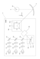
- FIG. 1 is a perspective view illustrating a schematic configuration of AR glasses according to a first embodiment.
- FIG. 2 is a diagram illustrating a schematic configuration of a projection unit according to the first embodiment.
- FIG. 3 is a block diagram showing the configuration of a projection unit and a detection unit according to the first embodiment.
- FIG. 4 is a block diagram showing the configuration of a signal processing unit according to the first embodiment.
- FIG. 5 is a diagram illustrating a schematic diagram of the first and second captured video signals acquired by the camera according to the first embodiment.
- FIG. 6 is a schematic diagram for explaining the thinning process by the input processing unit according to the first embodiment.
- Fig. 7A is a diagram showing frame image generation according to a comparative example, and Fig.
- FIG. 7B is a diagram showing frame image generation according to the first embodiment.
- FIG. 8 is a flowchart showing a frame image generating process performed by the image generating device according to the first embodiment.
- FIG. 9 is a flowchart showing details of the storage process according to the first embodiment.
- FIG. 10 is a block diagram showing a configuration of a signal processing unit according to the first modification of the first embodiment.
- FIG. 11 is a schematic diagram for explaining the thinning process by the input processing unit according to the first modification of the first embodiment.
- FIG. 12 is a block diagram showing a configuration of a signal processing unit according to the second modification of the first embodiment. In FIG. FIG. FIG.
- FIG. 13 is a diagram illustrating a first image area being set to one of five areas based on the viewpoint position, according to the third modification of the first embodiment.
- FIG. 14 is a diagram showing the scanning speed of the second mirror in a case where five areas are respectively set as the first image area according to the third modification of the first embodiment.
- FIG. 15 is a block diagram showing a configuration of a signal processing unit according to the second embodiment.
- FIG. 16 is a diagram illustrating a first captured video signal and a second captured video signal acquired by the camera when the first exposure time is longer than the second exposure time according to the second embodiment.
- FIG. 17(a) to (d) are diagrams illustrating schematic diagrams of video signals stored in two first buffers and two second buffers when the first exposure time is longer than the second exposure time in the second embodiment.
- Fig. 18A is a diagram illustrating the generation of a frame image when the first exposure time is longer than the second exposure time according to the second embodiment.
- Fig. 18B is a diagram illustrating an example of a frame image when the first exposure time is longer than the second exposure time according to the second embodiment.
- FIG. 19 is a diagram illustrating a first captured video signal and a second captured video signal acquired by the camera when the first exposure time is shorter than the second exposure time according to the second embodiment.
- Figures 20(a) to (d) are diagrams showing schematic diagrams of video signals stored in two first buffers and two second buffers when the first exposure time is shorter than the second exposure time in embodiment 2.
- Fig. 21A is a diagram illustrating the generation of a frame image when the first exposure time is shorter than the second exposure time according to the second embodiment.
- Fig. 21B is a diagram illustrating an example of a frame image when the first exposure time is shorter than the second exposure time according to the second embodiment.
- FIG. 22 is a flowchart showing a frame image generating process performed by the image generating device according to the second embodiment.
- FIG. 23 is a block diagram showing a configuration of a signal processing unit according to the third embodiment.
- Fig. 24A is a diagram showing a frame image generation according to the third embodiment, and
- Fig. 24B is an example diagram showing a frame image according to the third embodiment.
- FIG. 25 is a block diagram showing a configuration of a signal processing unit according to another modification.
- the present invention is applied to an image generating device for a head mounted display.
- head mounted displays include AR glasses, AR goggles, VR glasses, and VR goggles.
- the head mounted display in the following embodiment is AR glasses.
- the following embodiment is one embodiment of the present invention, and the present invention is not limited to the following embodiment.
- the present invention is not limited to image generating devices for head mounted displays, but can also be applied to image generating devices such as in-vehicle head-up displays.
- the mutually orthogonal X, Y, and Z axes are indicated in addition to the front, back, left, right, up, and down directions of the AR glasses 1.
- the positive X-axis, positive Y-axis, and positive Z-axis directions correspond to the right, rear, and upward directions of the AR glasses 1, respectively.
- the AR glasses 1 include a frame 2, a pair of image generating devices 3, and a pair of mirrors 4.
- the AR glasses 1 are worn on the user's head, similar to regular eyeglasses.
- the frame 2 holds a pair of image generating devices 3 and a pair of mirrors 4.
- the frame 2 is composed of a front portion 2a and a pair of support portions 2b.
- the pair of support portions 2b extend rearward from the right and left ends of the front portion 2a.
- the front portion 2a is positioned in front of a pair of eyes E of the user.
- the frame 2 is composed of an opaque material.
- the frame 2 may also be composed of a transparent material.
- the pair of image generating devices 3 are symmetrical with respect to the Y-Z plane that passes through the center of the AR glasses 1.
- the image generating devices 3 generate an image at the eye E of a user who wears the AR glasses 1 on their head.
- Mirror 4 is a mirror with a concave reflective surface, and is installed on the inner surface of the front portion 2a of the frame 2. Mirror 4 almost completely reflects the light projected from the corresponding projection portion 11, and guides it to the user's eye E.
- the image generating device 3 includes a projection unit 11, a detection unit 12, and a camera 13.
- the projection unit 11 is installed on the inner surface of the support unit 2b.
- the projection unit 11 projects light modulated by a video signal onto the corresponding mirror 4.
- the light from the projection unit 11 reflected by the mirror 4 is irradiated onto the fovea centralis, which is located at the center of the retina in the eye E. This allows the user to visually grasp the frame image 20 (see Figure 2) generated by the image generation device 3.
- the pair of detection units 12 are installed on the inner surface of the front surface 2a between the pair of mirrors 4.
- the detection units 12 are used to detect the user's line of sight.
- the pair of cameras 13 are installed on the outer surface of the front part 2a, in front of the pair of mirrors 4.
- the cameras 13 capture the field of view of the cameras 13.
- the field of view of the cameras 13 is in front of the AR glasses 1.
- FIG. 2 is a diagram showing a schematic configuration of the projection unit 11.
- Light sources 101, 102, and 103 are, for example, semiconductor laser light sources.
- Light source 101 emits laser light with a red wavelength in the range of 635 nm to 645 nm
- light source 102 emits laser light with a green wavelength in the range of 510 nm to 530 nm
- light source 103 emits laser light with a blue wavelength in the range of 440 nm to 460 nm.
- a color image is generated as the frame image 20 described below, so the projection unit 11 is equipped with light sources 101, 102, and 103 capable of emitting red, green, and blue laser light.
- the projection unit 11 may be equipped with only one light source corresponding to the color of the image.
- the projection unit 11 may also be configured to be equipped with two light sources with different emission wavelengths.
- Mirror 131 almost completely reflects the red light that passes through aperture 121.
- Dichroic mirror 132 reflects the green light that passes through aperture 122 and transmits the red light reflected by mirror 131.
- Dichroic mirror 133 reflects the blue light that passes through aperture 123 and transmits the red and green light that passes through dichroic mirror 132.
- Mirror 131 and the two dichroic mirrors 132 and 133 are positioned so as to align the optical axes of the light of each color emitted from light sources 101, 102, and 103.
- the first scanning unit 140 reflects the light that has passed through the dichroic mirror 133.
- the first scanning unit 140 is, for example, a MEMS (Micro Electro Mechanical System) mirror.
- the first scanning unit 140 has a configuration for rotating the first mirror 141, on which the light that has passed through the dichroic mirror 133 is incident, around an axis 141a parallel to the Z-axis direction in response to a drive signal.
- the rotation of the first mirror 141 changes the reflection direction of the light.
- the light reflected by the first mirror 141 is scanned along a scanning line extending in the X-axis direction on the retina of the eye E, as described below.
- the relay optical system 150 directs the light reflected by the first scanning unit 140 toward the center of the second mirror 161 of the second scanning unit 160. That is, the light incident on the first scanning unit 140 is deflected by the first mirror 141 at a predetermined deflection angle.
- the relay optical system 150 directs the light at each deflection angle toward the center of the second mirror 161.
- the relay optical system 150 also has multiple mirrors, and reflects the light reflected by the first scanning unit 140 by the multiple mirrors and directs it toward the second scanning unit 160. This makes it possible to realize a long optical path length inside the relay optical system 150 and suppress the deflection angle of the light when viewed from the second mirror 161.
- the second scanning unit 160 reflects the light that has passed through the relay optical system 150.
- the second scanning unit 160 is, for example, a MEMS mirror.
- the second scanning unit 160 has a configuration that rotates the second mirror 161, on which the light that has passed through the relay optical system 150 is incident, around an axis 161a parallel to the XY plane in response to a drive signal.
- the direction in which the light is reflected changes as the second mirror 161 rotates.
- the scanning line on the retina of the eye E along which the light is scanned by the first scanning unit 140 is changed in the Z-axis direction as described below.
- the light reflected by the second scanning unit 160 i.e., the light emitted from the projection unit 11, is reflected by the mirror 4 and forms a frame image 20 on the retina of the eye E.
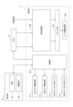
- FIG. 3 is a block diagram showing the configuration of the projection unit 11 and the detection unit 12.
- the detection unit 12 includes a light source 12a and an image sensor 12b, and is connected to the control unit 201 of the projection unit 11.
- the light source 12a is, for example, an LED that emits light of an infrared wavelength.
- the image sensor 12b is, for example, a CMOS image sensor or a CCD image sensor.
- the light source 12a irradiates light onto the user's eye E in response to instructions from the control unit 201.
- the image sensor 12b captures an image of the user's eye E in response to instructions from the control unit 201, and outputs the captured image to the control unit 201.
- the camera 13 In response to instructions from the control unit 201, the camera 13 captures an image of its field of view, generates a video signal, and outputs the generated video signal to the signal processing unit 300 of the corresponding projection unit 11.
- the left camera 13 outputs the generated video signal to the signal processing unit 300 of the left projection unit 11
- the right camera 13 outputs the generated video signal to the signal processing unit 300 of the right projection unit 11.
- the camera 13 of embodiment 1 outputs a first captured video signal for high resolution and a second captured video signal for low resolution, as described below.
- the projection unit 11 includes a control unit 201, a first mirror drive circuit 211, a second mirror drive circuit 212, a first mirror monitor sensor 213, a second mirror monitor sensor 214, a signal processing unit 300, a line memory 221, and a laser drive circuit 222.
- the control unit 201 includes an arithmetic processing unit such as a CPU or FPGA, and memory.
- the control unit 201 detects the user's line of sight based on the captured image from the detection unit 12, for example, by the dark pupil method, the bright pupil method, or the corneal reflex method.
- the control unit 201 acquires the viewpoint position in the frame image 20 formed on the user's retina based on the detected line of sight of the user.
- the control unit 201 also controls the signal processing unit 300 to process video signals from the camera 13 and external devices.
- the first mirror drive circuit 211 drives the first mirror 141 of the first scanning unit 140 in response to a drive signal from the control unit 201.
- the second mirror drive circuit 212 drives the second mirror 161 of the second scanning unit 160 in response to a drive signal from the control unit 201.
- the first mirror monitor sensor 213 is installed on the first mirror 141 and outputs a detection signal corresponding to the rotation of the first mirror 141 to the control unit 201.
- the second mirror monitor sensor 214 is installed on the second mirror 161 and outputs a detection signal corresponding to the rotation of the second mirror 161 to the control unit 201. Based on the detection signals from the first mirror monitor sensor 213 and the second mirror monitor sensor 214, the control unit 201 outputs drive signals to the first mirror drive circuit 211 and the second mirror drive circuit 212 so that the first mirror 141 and the second mirror 161 rotate with the desired drive waveform.
- the signal processing unit 300 processes the video signals from the camera 13 and external devices, and generates one line's worth of video signals. The configuration of the signal processing unit 300 will be described later with reference to FIG. 4.
- the line memory 221 outputs one line's worth of video signals output from the signal processing unit 300 to the laser driving circuit 222.
- the laser driving circuit 222 drives the light sources 101, 102, and 103 to emit light modulated by the one line's worth of video signals output from the line memory 221.
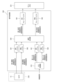
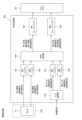
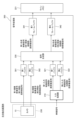
- FIG. 4 is a block diagram showing the configuration of the signal processing unit 300.
- the signal processing unit 300 includes a first buffer 301, a second buffer 302, an input processing unit 310, a first buffer 321, a second buffer 322, a signal synthesis unit 330, a first frame buffer 341, and a second frame buffer 342.
- the imaging processing unit 230 is composed of the camera 13.
- the camera 13 captures an image of the field of view and generates a first imaging video signal for high resolution and a second imaging video signal for low resolution.
- the first buffer 301 is a memory that temporarily stores the first imaging video signal output from the camera 13 (imaging processing unit 230).
- the second buffer 302 is a memory that temporarily stores the second imaging video signal output from the camera 13 (imaging processing unit 230).
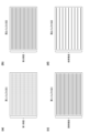
- FIG. 5 is a diagram showing a schematic diagram of the first and second image capture signals acquired by the camera 13.
- Camera 13 generates a first imaging video signal in a first imaging period set within one frame, and generates a second imaging video signal in a second imaging period different from the first imaging period within one frame.
- the first imaging period is the first half of one frame
- the second imaging period is the second half of one frame
- the lengths of the first imaging period and the second imaging period are the same.
- the video signals for each line stored in the first buffer 301 and the second buffer 302 are shown by solid and dashed lines.
- the odd-numbered first captured video signals from the top are shown by solid lines
- the even-numbered first captured video signals from the top are shown by dashed lines.
- 17 lines of first captured video signals are shown in the first buffer 301 in FIG. 5, but the actual number of lines is several levels more.
- the second captured video signals stored in the second buffer 302 the second captured video signals with the dashed lines of the first buffer 301 omitted are shown by solid lines.
- the second imaging video signal of the second buffer 302 is a signal in which every other line of the first imaging video signal of the first buffer 301 is thinned out by driving each light receiving unit in the camera 13.
- the manner in which the lines are thinned out is not limited to this, and for example, the second imaging video signal of the second buffer 302 may be a signal in which every third or more lines of the first imaging video signal of the first buffer 301 are thinned out.
- the video signal from the external device is, for example, a video signal related to CG (Computer Graphics). This video signal has the same resolution as the first captured video signal output from camera 13.
- Input processing unit 310 performs thinning processing on the video signal input from the external device.
- First buffer 321 is a memory that temporarily stores the video signal input from the external device, i.e., the first input video signal that has not been thinned out by input processing unit 310.
- Second buffer 322 is a memory that temporarily stores the second input video signal after thinning processing by input processing unit 310.
- FIG. 6 is a schematic diagram for explaining the thinning process performed by the input processing unit 310.
- the input processing unit 310 generates a first input video signal and a second input video signal, each having a different resolution, from a video signal from an external device.
- the video signals for each line stored in the first buffer 321 and the second buffer 322 are shown by solid and dashed lines.
- the odd-numbered first input video signals from the top are shown by solid lines
- the even-numbered first input video signals from the top are shown by dashed lines.
- 17 lines of first input video signals are shown in the first buffer 321 in FIG. 6, but the actual number of lines is several lines more.
- the second input video signal stored in the second buffer 322 is a signal in which the dashed lines of the first buffer 321 have been thinned out.
- the second input video signal of the second buffer 322 is a signal in which every other line of the first input video signal of the first buffer 321 is thinned out.
- the manner in which the lines are thinned out is not limited to this, and for example, the second input video signal may be a signal in which every third or more lines of the first input video signal of the first buffer 321 are thinned out.
- the second input video signal may be generated by mixing adjacent lines of the first input video signal stored in the first buffer 321. In the mixing process, for example, two adjacent lines are replaced with one line calculated as the average value of the signals of these two lines.
- the signal synthesis unit 330 synthesizes the first captured video signal for high resolution stored in the first buffer 301 and the first input video signal for high resolution stored in the first buffer 321 to generate a first synthesized video signal for high resolution for one frame.
- the signal synthesis unit 330 also synthesizes the second captured video signal for low resolution stored in the second buffer 302 and the second input video signal for low resolution stored in the second buffer 322 to generate a second synthesized video signal for low resolution for one frame.
- the first frame buffer 341 stores one frame of the first composite video signal for high resolution generated by the signal synthesis unit 330.
- the second frame buffer 342 stores one frame of the second composite video signal for low resolution generated by the signal synthesis unit 330.
- the first frame buffer 34 in response to a control signal from the control unit 201 (see FIG. 3), sequentially outputs one line of the first composite video signal of one stored frame of the first composite video signal to the line memory 221.
- the second frame buffer 342 in response to a control signal from the control unit 201, sequentially outputs one line of the second composite video signal of one stored frame of the second composite video signal to the line memory 221. Either one of the one line of the first composite video signal from the first frame buffer 341 or the one line of the second composite video signal from the second frame buffer 342 is input to the line memory 221.
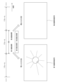
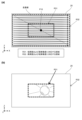
- FIG. 7(a) is a schematic diagram showing the generation of a frame image 20 according to a comparative example.
- the resolution (number of scanning lines) of the frame image 20 is set low in the outer area of a predetermined range including the user's viewpoint position P10, as shown in FIG. 7(b). This makes it less likely that the user's eyes will become tired.
- a first composite video signal with a large number of scanning lines (high resolution) is stored in advance in the first frame buffer 341, and a second composite video signal with a small number of scanning lines (low resolution) is stored in the second frame buffer 342.
- the control unit 201 then switches between the first composite video signal from the first frame buffer 341 and the second composite video signal from the second frame buffer 342 according to the viewpoint position P10 to generate the frame image 20. This makes it possible to suppress the above-mentioned display delay and realize image generation that tracks the user's viewpoint position P10.
- FIG. 7(b) is a diagram showing a schematic diagram of the generation of a frame image 20 according to the first embodiment.
- the control unit 201 detects the user's line of sight based on the captured image acquired by the detection unit 12, and acquires the viewpoint position P10 on the frame image 20 based on the detected line of sight.
- the control unit 201 controls the light sources 101, 102, 103, the first scanning unit 140, and the second scanning unit 160 so that an image is generated by applying a high-resolution first composite video signal from the first frame buffer 341 to a first image region R1 of a predetermined number of scanning lines that includes the viewpoint position P10 on the frame image 20.
- the control unit 201 also controls the light sources 101, 102, 103, the first scanning unit 140, and the second scanning unit 160 so that an image is generated by applying a low-resolution second composite video signal from the second frame buffer 342 to a second image region R2 other than the first image region R1 of the frame image 20.
- FIG. 7(b) for convenience, about five scanning lines are shown in the first image region R1, and about eight scanning lines in total are shown in the second image region R2, but the actual number of scanning lines is several levels more.
- the number of scanning lines included in the first image region R1 may be changed as appropriate. Also, in FIG. 7(b), the first image region R1 has ranges with the same number of scanning lines above and below the viewpoint position P10 as the center, but the number of scanning lines corresponding to the upper range and the number of scanning lines corresponding to the lower range may be different from each other.
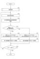
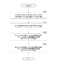
- FIG. 8 is a flowchart showing the process of generating a frame image 20 performed by the image generating device 3.
- the processing in steps S11 to S19 is related to the generation of a frame image 20 corresponding to one frame.
- the control unit 201 performs a storage process (S11). As a result, a first composite video signal for one frame of high resolution and a second composite video signal for one frame of low resolution are stored in the first frame buffer 341 and the second frame buffer 342, respectively, based on the video signal from the camera 13 and the video signal from the external device.
- FIG. 9 is a flowchart showing the details of the storage process of step S11 in FIG. 8. The process in FIG. 9 is executed by the control unit 201 controlling the imaging processing unit 230 and the signal processing unit 300.
- the imaging processor 230 (camera 13 in the first embodiment) generates a first imaging video signal for high resolution during the first imaging period, and generates a second imaging video signal for low resolution during the second imaging period.
- the imaging processor 230 then stores the generated first imaging video signal and second imaging video signal in the first buffer 301 and second buffer 302, respectively (S101).
- the input processing unit 310 generates a first input video signal for high resolution and a second input video signal for low resolution based on a video signal input from an external device. Then, the input processing unit 310 stores the generated first input video signal and second input video signal in the first buffer 321 and the second buffer 322, respectively (S102). Note that the processes of steps S101 and S102 are performed in parallel.
- the signal synthesis unit 330 synthesizes the first captured video signal stored in the first buffer 301 with the first input video signal of the same line as the first captured video signal among the first input video signals stored in the first buffer 321, to generate a first synthesized video signal for one frame of high resolution.
- the signal synthesis unit 330 then stores the generated first synthesized video signal in the first frame buffer 341 (S103).
- the signal synthesis unit 330 synthesizes the second captured video signal stored in the second buffer 302 with the second input video signal of the same line as the second captured video signal among the second input video signals stored in the second buffer 322, to generate a second synthesized video signal for one frame of low resolution.
- the signal synthesis unit 330 then stores the generated second synthesized video signal in the second frame buffer 342 (S104). Note that the processes of steps S103 and S104 are performed in parallel.
- the control unit 201 detects the user's viewpoint position P10 based on the captured image acquired by the detection unit 12 (S12).
- the control unit 201 sets the first image area R1 and the second image area R2 based on the viewpoint position P10 detected in step S12 (S13).
- the control unit 201 causes the first frame buffer 341 to output a high-resolution first composite video signal to the line memory 221 (S15). As a result, one line of image is generated by the first composite video signal from the first frame buffer 341. In parallel with this, the control unit 201 controls the second mirror drive circuit 212 so that the second mirror 161 rotates at the first scanning speed (S16). As a result, the spacing between vertically adjacent scan lines becomes narrower, as shown in the first image region R1 in FIG. 7(b).
- the control unit 201 causes the second frame buffer 342 to output a low-resolution second composite video signal to the line memory 221 (S17). As a result, one line of image is generated by the second composite video signal from the second frame buffer 342.
- the control unit 201 controls the second mirror drive circuit 212 so that the second mirror 161 rotates at a second scanning speed that is faster than the first scanning speed (S18). As a result, the spacing between vertically adjacent scanning lines becomes wider, as shown in the second image region R2 in FIG. 7(b).
- the control unit 201 determines whether or not image generation for one frame has been completed (S19). If image generation for one frame has not been completed (S19: NO), the process returns to step S12, and steps S12 to S18 are performed again. When image generation for one frame is completed in this manner (S19: YES), the process in FIG. 8 ends. Frame images 20 are generated continuously by repeating the process in FIG. 8.
- the camera 13 of this modified example outputs only a high-resolution video signal similar to the first captured video signal of embodiment 1.
- the input processing unit 350 performs a thinning process on the video signal input from the camera 13 similar to the thinning process performed by the input processing unit 310.
- the first buffer 301 temporarily stores the first captured video signal output from the camera 13 that has not been thinned out by the input processing unit 350.
- the second buffer 302 temporarily stores the second captured video signal that has been thinned out and generated by the input processing unit 350.
- the second imaging video signal in the second buffer 302 is a signal in which every other line of the first imaging video signal in the first buffer 301 is thinned out.
- the manner in which the lines are thinned out is not limited to this, and for example, the second imaging video signal may be a signal in which every third or more lines of the first imaging video signal in the first buffer 301 are thinned out.
- the second imaging video signal may be generated by mixing adjacent lines of the first imaging video signal stored in the first buffer 301. In the mixing process, for example, two adjacent lines are replaced with one line calculated as the average value of the signals of these two lines.
- the camera 13 only needs to output one type of first imaging video signal, and therefore the configuration and processing of the camera 13 can be simplified. Furthermore, as shown in the first embodiment, in a configuration in which the first imaging video signal and the second imaging video signal are obtained in two different imaging periods, if the subject moves at high speed, the position of the subject will differ in the two types of video signals. However, according to this modified example, since the camera 13 only outputs one type of first imaging video signal, the position of the subject will be the same in the first imaging video signal and the second imaging video signal generated by the input processing unit 350, even if the subject moves at high speed. This makes it possible to avoid any discomfort felt by the user based on the first imaging video signal and the second imaging video signal.
- the signal processing unit 300 in FIG. 12 omits the input processing unit 310, the first buffer 321, the second buffer 322, and the signal synthesis unit 330.
- the first captured video signal from the camera 13 is temporarily stored in the first buffer 301, and one frame of the first captured video signal is then output to the first frame buffer 341.
- the second captured video signal from the camera 13 is temporarily stored in the second buffer 302, and one frame of the second captured video signal is then output to the second frame buffer 342.
- the first captured video signal stored in the first frame buffer 341 and the second captured video signal stored in the second frame buffer 342 are selectively used according to the user's line of sight to generate one frame of image. Therefore, similar to the first embodiment, the image resolution (definition) can be smoothly switched between the first image region R1 near the user's line of sight and the other second image region R2.
- control unit 201 sets regions R11 to R15 as the first image region, respectively.
- Viewpoint regions R01 to R05 are obtained by dividing frame image 20 into five regions in the vertical direction (Z-axis direction).
- Regions R11 to R15 are regions set corresponding to viewpoint regions R01 to R05, and each includes a predetermined number of scanning lines.
- regions R11 to R15 are set as the first image region, regions other than regions R11 to R15 are set as the second image region, respectively.
- FIG. 14 shows the scanning speed of the second mirror 161 when the five regions R11 to R15 are each set as the first image region in this modified example.
- the scanning speed of the second mirror 161 is set as shown in the bottom graph of FIG. 14.
- the bottom graph of FIG. 14 shows the scanning speed of the second mirror 161 for scanning one line.
- the speed of the second mirror 161 is slower in regions R11 to R15.
- the control unit 201 sets the area including the viewpoint position P10 as the first image area out of a plurality of areas R11 to R15 that are previously formed by dividing the frame image 20 in a direction (Z-axis direction) that intersects with the scanning lines.
- the camera 13 of the first embodiment outputs two types of video signals, a first captured video signal for high resolution and a second captured video signal for low resolution, whereas the camera 13 of the second embodiment outputs two types of video signals, a first captured video signal for a first luminance and a second captured video signal for a second luminance.
- FIG. 15 is a block diagram showing the configuration of the signal processing unit 300 according to the second embodiment.
- the signal processing unit 300 in FIG. 15 differs in the two types of video signals output from the camera 13. That is, the camera 13 outputs a first imaged video signal for a first luminance and a first imaged video signal for a second luminance.
- the signal synthesis unit 330 synthesizes the first imaged video signal for a first luminance stored in the first buffer 301 with the first input video signal for high resolution stored in the first buffer 321 to generate a first synthesized video signal for the first luminance and high resolution for one frame.
- the signal synthesis unit 330 also synthesizes the second imaged video signal for a second luminance stored in the second buffer 302 with the second input video signal for low resolution stored in the second buffer 322 to generate a second synthesized video signal for the second luminance and low resolution for one frame.
- the control unit 201 sets a first image region R31 of a predetermined size including the viewpoint position P10.
- the first image region R31 corresponds to the user's visual field range of, for example, ⁇ 30° in the X-axis direction and ⁇ 10° in the Z-axis direction, with the viewpoint position P10 as the center.
- the control unit 201 applies a first composite video signal from the first frame buffer 341 to the first image region R31 including the viewpoint position P10, and causes light to be emitted from the light sources 101, 102, and 103.
- the control unit 201 applies a second composite video signal from the second frame buffer 342 to the second image region R32 other than the first image region R31, and causes light to be emitted from the light sources 101, 102, and 103.
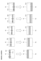
- FIG. 19 is a diagram showing a schematic diagram of the first and second captured video signals acquired by the camera 13 when the first exposure time is shorter than the second exposure time.
- the first exposure time is shorter than the second exposure time, compared to the example shown in FIG. 16.
- the first imaging video signal for the first luminance generated by the first exposure time is darker than the second imaging video signal for the second luminance generated by the second exposure time.
- 20(a) to (d) are schematic diagrams showing the video signals stored in the first buffer 301, the second buffer 302, the first buffer 321, and the second buffer 322, respectively.
- the first buffer 301 stores the first image pickup video signal for the first luminance generated by the camera 13, i.e., in the example of FIG. 19, the dark first image pickup video signal.
- the second buffer 302 stores the second image pickup video signal for the second luminance generated by the camera 13, i.e., in the example of FIG. 19, the bright second image pickup video signal.
- the first buffer 321 stores the first input video signal for high resolution
- the second buffer 322 stores the second input video signal for low resolution.
- the signal synthesis unit 330 synthesizes the first captured image signal as shown in Fig. 20(a) with the first input image signal as shown in Fig. 20(c) to generate a first synthesized image signal for the first luminance and high resolution.
- the signal synthesis unit 330 also synthesizes the second captured image signal as shown in Fig. 20(b) with the second input image signal as shown in Fig. 20(d) to generate a second synthesized image signal for the second luminance and low resolution.
- control unit 201 also sets a first image region R31 similar to that shown in FIG. 18(a), and applies the first composite video signal from the first frame buffer 341 to the first image region R31 including the viewpoint position P10.
- the control unit 201 also applies the second composite video signal from the second frame buffer 342 to the second image region R32 other than the first image region R31.
- the control unit 201 If the current scan line is included only in the second image region R32 (S21: YES), the control unit 201 outputs the second composite video signal from the second frame buffer 342 to the line memory 221 (S22). As a result, in the second embodiment, one line of an image is generated by the second composite video signal for the second luminance and low resolution.
- the imaging processing section 230 outputs a first imaging video signal for constructing a frame image 20 of a first luminance (first resolution) and a second imaging video signal for constructing a frame image 20 of a second luminance (second resolution).
- the first frame buffer 341 stores the first composite video signal (first imaging video signal)
- the second frame buffer 342 stores the second composite video signal (second imaging video signal).
- the signal synthesis unit 330 synthesizes the first captured image signal for high gradation stored in the first buffer 301 and the first input image signal for high gradation stored in the first buffer 321 to generate a first synthesized image signal for high gradation for one frame.
- the signal synthesis unit 330 also synthesizes the second captured image signal for low gradation stored in the second buffer 302 and the second input image signal for low gradation stored in the second buffer 322 to generate a second synthesized image signal for low gradation for one frame.
- FIG. 24(a) is a diagram showing a schematic diagram of the generation of a frame image 20 according to embodiment 3.
- the imaging processing unit 230 outputs a first imaging video signal for constructing a high gradation (first definition) frame image 20 and a second imaging video signal for constructing a low gradation (second definition) frame image 20.
- the first frame buffer 341 stores the first composite video signal (first imaging video signal)
- the second frame buffer 342 stores the second composite video signal (second imaging video signal).
- the first captured video signal stored in the first frame buffer 341 and the second captured video signal stored in the second frame buffer 342 are selectively used according to the user's line of sight to generate one frame of image. This allows smooth switching of the image gradation (resolution) between the first image region R31 near the user's line of sight and the other second image region R32.
- a high-gradation frame image 20 is displayed in the first image region R31 near the user's line of sight, and a low-gradation frame image 20 is displayed in the second image region R32 around the user's line of sight. This makes it possible to reduce eye fatigue for the user. Furthermore, even if the user has poor eyesight, the user can clearly grasp the subject by referring to the high-gradation frame image 20 in the first image region R31.
- the camera 13 outputs a first captured video signal corresponding to a high gradation (first gradation), and the imaging processing unit 230 has an input processing unit 350 that performs processing to reduce the gradation of the high gradation first captured video signal to generate a second captured video signal for a low gradation (second gradation).
- This configuration allows for smooth generation of high and low gradation video signals.
- the input processing unit 350 may be configured integrally with the camera 13.
- the video signal from the external device may be a first input video signal for high gradation and a second input video signal for low gradation. In this case, the input processing unit 310 is omitted.
- the configuration for processing video signals from an external device i.e., the input processing unit 310, the first buffer 321, the second buffer 322, and the signal synthesis unit 330, may be omitted.
- FIG. 25 is a block diagram showing the configuration of the signal processing unit 300 in this modified example.
- the detection of the viewpoint position P10 and the setting of the first image area and the second image area are performed for each line of image generation, but they may also be performed for each frame of image (frame image 20) generation.
- the input processing unit 350 performs thinning and mixing processes on the input first imaging video signal for high resolution to generate a second imaging video signal for low resolution, as shown in FIG. 11.
- the input processing unit 350 may perform complementation processes on the input second imaging video signal for low resolution to generate a first imaging video signal for high resolution.
- complementation processes impose a higher processing load than thinning and mixing processes, it is preferable that the video signal input to the input processing unit 350 is the first imaging video signal for high resolution.
- the input processing units 350 and 310 perform processing to reduce the number of gradations of the video signal to two gradations, but this is not limited thereto, and processing to reduce the number of gradations of the video signal to a number other than two gradations (for example, 16 gradations) may also be performed.
- two frame buffers the first frame buffer 341 and the second frame buffer 342, are used, but three or more frame buffers storing video signals with different definitions (resolution, brightness, gradation, combinations thereof, etc.) may be used to output video signals to the line memory 221.
- two of the three or more frame buffers are selected as the first frame buffer 341 and the second frame buffer 342 to process the image display. Which of the three or more frame buffers is used to generate the display image is selected, for example, by the user.
- three buffers are provided between the input processing unit 350 and the signal synthesis unit 330 for temporarily storing the captured image video signals of the three levels of definition
- three buffers are provided between the input processing unit 310 and the signal synthesis unit 330 for temporarily storing the input image signals of the three levels of definition.
- the signal synthesis unit 330 then synthesizes the captured image video signals and the input video signals of the corresponding levels of definition, and outputs the synthesized synthesized video signals of the three levels of definition to the corresponding frame buffers.
- An imaging processing section including a camera for imaging a field of view, and outputting a first imaging video signal for constructing a frame image of a first resolution and a second imaging video signal for constructing a frame image of a second resolution different from the first resolution; a first frame buffer for storing the first image pickup video signal; a second frame buffer for storing the second image signal; a light source that emits light for constructing the frame image; A scanning unit that scans the light emitted from the light source; A detection unit for detecting a line of sight of a user; A control unit, The control unit is controlling the light source and the scanning unit so that an image is generated by applying the first captured video signal from the first frame buffer to a first image region including a viewpoint position on the frame image corresponding to the line of sight; controlling the light source and the scanning unit so that an image is generated by applying the second captured video signal from the second frame buffer to a second image area other than the first image area of the frame image; 1.
- An image generating apparatus comprising:
- the first definition and the second definition are a first resolution and a second resolution of the frame image defined by a scanning speed of the scanning unit, respectively;
- the first resolution is higher than the second resolution.
Landscapes
- Physics & Mathematics (AREA)
- General Physics & Mathematics (AREA)
- Engineering & Computer Science (AREA)
- Optics & Photonics (AREA)
- Computer Hardware Design (AREA)
- Theoretical Computer Science (AREA)
- Multimedia (AREA)
- Signal Processing (AREA)
- Controls And Circuits For Display Device (AREA)
- Control Of Indicators Other Than Cathode Ray Tubes (AREA)
Priority Applications (2)
| Application Number | Priority Date | Filing Date | Title |
|---|---|---|---|
| JP2024568708A JPWO2024147249A1 (https=) | 2023-01-05 | 2023-12-01 | |
| US19/244,975 US20250314893A1 (en) | 2023-01-05 | 2025-06-20 | Image generation device and head-mounted display |
Applications Claiming Priority (2)
| Application Number | Priority Date | Filing Date | Title |
|---|---|---|---|
| JP2023-000741 | 2023-01-05 | ||
| JP2023000741 | 2023-01-05 |
Related Child Applications (1)
| Application Number | Title | Priority Date | Filing Date |
|---|---|---|---|
| US19/244,975 Continuation US20250314893A1 (en) | 2023-01-05 | 2025-06-20 | Image generation device and head-mounted display |
Publications (1)
| Publication Number | Publication Date |
|---|---|
| WO2024147249A1 true WO2024147249A1 (ja) | 2024-07-11 |
Family
ID=91803868
Family Applications (1)
| Application Number | Title | Priority Date | Filing Date |
|---|---|---|---|
| PCT/JP2023/043069 Ceased WO2024147249A1 (ja) | 2023-01-05 | 2023-12-01 | 画像生成装置およびヘッドマウントディスプレイ |
Country Status (3)
| Country | Link |
|---|---|
| US (1) | US20250314893A1 (https=) |
| JP (1) | JPWO2024147249A1 (https=) |
| WO (1) | WO2024147249A1 (https=) |
Citations (4)
| Publication number | Priority date | Publication date | Assignee | Title |
|---|---|---|---|---|
| US20140002587A1 (en) * | 2012-06-29 | 2014-01-02 | Jerry G. Aguren | Wide field-of-view stereo vision platform with dynamic control of immersive or heads-up display operation |
| WO2017195650A1 (ja) * | 2016-05-13 | 2017-11-16 | ソニー株式会社 | 生成装置および生成方法、並びに、再生装置および再生方法 |
| JP2020167659A (ja) * | 2019-03-29 | 2020-10-08 | 株式会社ソニー・インタラクティブエンタテインメント | 画像処理装置、ヘッドマウントディスプレイ、および画像表示方法 |
| JP2021518679A (ja) * | 2018-03-16 | 2021-08-02 | マジック リープ, インコーポレイテッドMagic Leap,Inc. | ディスプレイシステムのための深度ベースの中心窩化レンダリング |
-
2023
- 2023-12-01 JP JP2024568708A patent/JPWO2024147249A1/ja active Pending
- 2023-12-01 WO PCT/JP2023/043069 patent/WO2024147249A1/ja not_active Ceased
-
2025
- 2025-06-20 US US19/244,975 patent/US20250314893A1/en not_active Abandoned
Patent Citations (4)
| Publication number | Priority date | Publication date | Assignee | Title |
|---|---|---|---|---|
| US20140002587A1 (en) * | 2012-06-29 | 2014-01-02 | Jerry G. Aguren | Wide field-of-view stereo vision platform with dynamic control of immersive or heads-up display operation |
| WO2017195650A1 (ja) * | 2016-05-13 | 2017-11-16 | ソニー株式会社 | 生成装置および生成方法、並びに、再生装置および再生方法 |
| JP2021518679A (ja) * | 2018-03-16 | 2021-08-02 | マジック リープ, インコーポレイテッドMagic Leap,Inc. | ディスプレイシステムのための深度ベースの中心窩化レンダリング |
| JP2020167659A (ja) * | 2019-03-29 | 2020-10-08 | 株式会社ソニー・インタラクティブエンタテインメント | 画像処理装置、ヘッドマウントディスプレイ、および画像表示方法 |
Also Published As
| Publication number | Publication date |
|---|---|
| US20250314893A1 (en) | 2025-10-09 |
| JPWO2024147249A1 (https=) | 2024-07-11 |
Similar Documents
| Publication | Publication Date | Title |
|---|---|---|
| JP7709198B2 (ja) | 画像投影システム | |
| US6523955B1 (en) | Method for improving optic perceptive faculty by modifying the retinal image | |
| US6201517B1 (en) | Stereoscopic image display apparatus | |
| US6227667B1 (en) | Apparatus for recording the retina reflex image and for superimposing of additional images in the eye | |
| JP6184983B2 (ja) | 画像生成システム及び画像生成方法 | |
| JP4682470B2 (ja) | スキャン型ディスプレイ装置 | |
| JP3571501B2 (ja) | 映像観察装置 | |
| US8061845B2 (en) | Image display system and image display method | |
| EP3729182B1 (en) | Eye tracking for head-worn display | |
| EP3514606A1 (en) | Eye tracking for head-worn display | |
| EP1736811A1 (en) | Scanning display | |
| JP2009192561A (ja) | 画像表示装置 | |
| WO2024147249A1 (ja) | 画像生成装置およびヘッドマウントディスプレイ | |
| JPH11109279A (ja) | 映像表示装置 | |
| JP2006195084A (ja) | 表示装置 | |
| WO2025047507A1 (ja) | 画像生成装置およびヘッドマウントディスプレイ | |
| JPH11109278A (ja) | 映像表示装置 | |
| JP2021170699A (ja) | 電子機器 | |
| WO2025105113A1 (ja) | 画像生成装置およびヘッドマウントディスプレイ | |
| WO2025047508A1 (ja) | 画像生成装置およびヘッドマウントディスプレイ | |
| WO2024084819A1 (ja) | 画像生成装置 | |
| JP2007121581A (ja) | 走査型画像表示装置、撮像装置および画像表示システム | |
| WO2025225322A1 (ja) | 画像表示装置、ヘッドマウントディスプレイおよびヘッドアップディスプレイ | |
| JP2012080285A (ja) | 撮像装置及びそれを備えたヘッドマウントディスプレイ | |
| JP2006350257A (ja) | 走査型表示装置 |
Legal Events
| Date | Code | Title | Description |
|---|---|---|---|
| 121 | Ep: the epo has been informed by wipo that ep was designated in this application |
Ref document number: 23914737 Country of ref document: EP Kind code of ref document: A1 |
|
| WWE | Wipo information: entry into national phase |
Ref document number: 2024568708 Country of ref document: JP |
|
| NENP | Non-entry into the national phase |
Ref country code: DE |
|
| 122 | Ep: pct application non-entry in european phase |
Ref document number: 23914737 Country of ref document: EP Kind code of ref document: A1 |