WO2024147249A1 - Image generation device and head-mounted display - Google Patents
Image generation device and head-mounted display Download PDFInfo
- Publication number
- WO2024147249A1 WO2024147249A1 PCT/JP2023/043069 JP2023043069W WO2024147249A1 WO 2024147249 A1 WO2024147249 A1 WO 2024147249A1 JP 2023043069 W JP2023043069 W JP 2023043069W WO 2024147249 A1 WO2024147249 A1 WO 2024147249A1
- Authority
- WO
- WIPO (PCT)
- Prior art keywords
- image
- video signal
- frame
- imaging
- resolution
- Prior art date
Links
- 239000000872 buffer Substances 0.000 claims abstract description 210
- 238000003384 imaging method Methods 0.000 claims abstract description 169
- 238000000034 method Methods 0.000 claims description 54
- 239000002131 composite material Substances 0.000 claims description 46
- 230000008569 process Effects 0.000 claims description 35
- 230000015572 biosynthetic process Effects 0.000 claims description 29
- 238000003786 synthesis reaction Methods 0.000 claims description 29
- 238000001514 detection method Methods 0.000 claims description 16
- 230000003287 optical effect Effects 0.000 claims description 16
- 210000003128 head Anatomy 0.000 claims description 9
- 238000010586 diagram Methods 0.000 description 56
- 239000011521 glass Substances 0.000 description 22
- 230000004048 modification Effects 0.000 description 20
- 238000012986 modification Methods 0.000 description 20
- 230000004044 response Effects 0.000 description 10
- 230000000694 effects Effects 0.000 description 9
- 210000001525 retina Anatomy 0.000 description 6
- 208000003464 asthenopia Diseases 0.000 description 5
- 230000000052 comparative effect Effects 0.000 description 4
- 230000004438 eyesight Effects 0.000 description 4
- 230000008859 change Effects 0.000 description 3
- 239000007787 solid Substances 0.000 description 3
- 230000002194 synthesizing effect Effects 0.000 description 3
- 210000001747 pupil Anatomy 0.000 description 2
- 230000009467 reduction Effects 0.000 description 2
- 230000000007 visual effect Effects 0.000 description 2
- 230000003190 augmentative effect Effects 0.000 description 1
- 210000000873 fovea centralis Anatomy 0.000 description 1
- 239000000463 material Substances 0.000 description 1
- 238000011946 reduction process Methods 0.000 description 1
- 230000011514 reflex Effects 0.000 description 1
- 239000004065 semiconductor Substances 0.000 description 1
- 239000012780 transparent material Substances 0.000 description 1
Images


Classifications
-
- G—PHYSICS
- G02—OPTICS
- G02B—OPTICAL ELEMENTS, SYSTEMS OR APPARATUS
- G02B26/00—Optical devices or arrangements for the control of light using movable or deformable optical elements
- G02B26/08—Optical devices or arrangements for the control of light using movable or deformable optical elements for controlling the direction of light
- G02B26/10—Scanning systems
-
- G—PHYSICS
- G02—OPTICS
- G02B—OPTICAL ELEMENTS, SYSTEMS OR APPARATUS
- G02B27/00—Optical systems or apparatus not provided for by any of the groups G02B1/00 - G02B26/00, G02B30/00
- G02B27/02—Viewing or reading apparatus
-
- G—PHYSICS
- G09—EDUCATION; CRYPTOGRAPHY; DISPLAY; ADVERTISING; SEALS
- G09G—ARRANGEMENTS OR CIRCUITS FOR CONTROL OF INDICATING DEVICES USING STATIC MEANS TO PRESENT VARIABLE INFORMATION
- G09G5/00—Control arrangements or circuits for visual indicators common to cathode-ray tube indicators and other visual indicators
- G09G5/36—Control arrangements or circuits for visual indicators common to cathode-ray tube indicators and other visual indicators characterised by the display of a graphic pattern, e.g. using an all-points-addressable [APA] memory
- G09G5/37—Details of the operation on graphic patterns
- G09G5/377—Details of the operation on graphic patterns for mixing or overlaying two or more graphic patterns
-
- G—PHYSICS
- G09—EDUCATION; CRYPTOGRAPHY; DISPLAY; ADVERTISING; SEALS
- G09G—ARRANGEMENTS OR CIRCUITS FOR CONTROL OF INDICATING DEVICES USING STATIC MEANS TO PRESENT VARIABLE INFORMATION
- G09G5/00—Control arrangements or circuits for visual indicators common to cathode-ray tube indicators and other visual indicators
- G09G5/36—Control arrangements or circuits for visual indicators common to cathode-ray tube indicators and other visual indicators characterised by the display of a graphic pattern, e.g. using an all-points-addressable [APA] memory
- G09G5/39—Control of the bit-mapped memory
- G09G5/395—Arrangements specially adapted for transferring the contents of the bit-mapped memory to the screen
- G09G5/397—Arrangements specially adapted for transferring the contents of two or more bit-mapped memories to the screen simultaneously, e.g. for mixing or overlay
-
- H—ELECTRICITY
- H04—ELECTRIC COMMUNICATION TECHNIQUE
- H04N—PICTORIAL COMMUNICATION, e.g. TELEVISION
- H04N5/00—Details of television systems
- H04N5/64—Constructional details of receivers, e.g. cabinets or dust covers
Definitions
- the present invention relates to an image generating device and a head-mounted display that generate images by scanning light.
- known image generating devices that generate images by scanning light include head-mounted displays such as goggles and glasses that realize AR (Augmented Reality) and VR (Virtual Reality).
- head-mounted displays such as goggles and glasses that realize AR (Augmented Reality) and VR (Virtual Reality).
- AR Augmented Reality
- VR Virtual Reality
- light based on a video signal is directed toward a translucent display, and the reflected light is directed toward the user's eyes.
- light based on a video signal is directly directed toward the user's eyes.
- Patent Document 1 describes an apparatus that realizes a first line density in a first portion of an image and a second line density lower than the first line density in a second portion of the image by controlling the rotation of the fast axis and slow axis of a MEMS mirror, and determines the position of the first portion of the image based on the line of sight of the eye.
- the resolution of the image in the second portion that does not correspond to the line of sight is lower than the resolution of the image in the first portion that corresponds to the line of sight, reducing eye fatigue for the user.
- a video signal obtained by capturing an image in front of the user can be used as a video signal for modulating the light used to generate the image. This allows the user to grasp the scenery in front of them from the captured image, even if the goggles or glasses described above are not particularly see-through.
- the image definition of the portion of the image corresponding to the user's line of sight different from the image definition of the other portions so that the user can view the image more comfortably.
- the present invention aims to provide an image generating device and a head-mounted display that can smoothly switch between the image resolution of a first image area near the user's line of sight and a second image area elsewhere.
- the image generating device includes a camera that captures an image of a field of view, an imaging processing unit that outputs a first imaging video signal for constructing a frame image of a first resolution and a second imaging video signal for constructing a frame image of a second resolution different from the first resolution, a first frame buffer that stores the first imaging video signal, a second frame buffer that stores the second imaging video signal, a light source that emits light for constructing the frame image, a scanning unit that scans the light emitted from the light source, a detection unit that detects the user's line of sight, and a control unit.
- the control unit controls the light source and the scanning unit so that an image is generated by applying the first imaging video signal from the first frame buffer to a first image area including a viewpoint position on the frame image corresponding to the line of sight, and controls the light source and the scanning unit so that an image is generated by applying the second imaging video signal from the second frame buffer to a second image area of the frame image other than the first image area.
- the first captured video signal stored in the first frame buffer and the second captured video signal stored in the second frame buffer are selectively used according to the user's line of sight to generate one frame of image. This allows smooth switching of image resolution between the first image area near the user's line of sight and the other second image area.
- the head mounted display according to the second aspect of the present invention comprises the image generating device according to the first aspect, a frame that holds the image generating device, and an optical system that guides light from the image generating device to the eyes of the user who wears the head mounted display on his or her head.
- the head mounted display of this embodiment provides the same effects as the first embodiment.
- the user can grasp the scenery captured by the camera through the frame image generated by the image generating device.
- the present invention provides an image generating device and a head mounted display that can smoothly switch between the image resolution of a first image area near the user's line of sight and a second image area elsewhere.
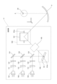
- FIG. 1 is a perspective view illustrating a schematic configuration of AR glasses according to a first embodiment.
- FIG. 2 is a diagram illustrating a schematic configuration of a projection unit according to the first embodiment.
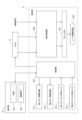
- FIG. 3 is a block diagram showing the configuration of a projection unit and a detection unit according to the first embodiment.
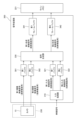
- FIG. 4 is a block diagram showing the configuration of a signal processing unit according to the first embodiment.
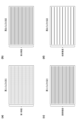
- FIG. 5 is a diagram illustrating a schematic diagram of the first and second captured video signals acquired by the camera according to the first embodiment.
- FIG. 6 is a schematic diagram for explaining the thinning process by the input processing unit according to the first embodiment.
- Fig. 7A is a diagram showing frame image generation according to a comparative example, and Fig.
- FIG. 7B is a diagram showing frame image generation according to the first embodiment.
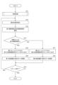
- FIG. 8 is a flowchart showing a frame image generating process performed by the image generating device according to the first embodiment.
- FIG. 9 is a flowchart showing details of the storage process according to the first embodiment.
- FIG. 10 is a block diagram showing a configuration of a signal processing unit according to the first modification of the first embodiment.
- FIG. 11 is a schematic diagram for explaining the thinning process by the input processing unit according to the first modification of the first embodiment.
- FIG. 12 is a block diagram showing a configuration of a signal processing unit according to the second modification of the first embodiment. In FIG. FIG. FIG.
- FIG. 13 is a diagram illustrating a first image area being set to one of five areas based on the viewpoint position, according to the third modification of the first embodiment.
- FIG. 14 is a diagram showing the scanning speed of the second mirror in a case where five areas are respectively set as the first image area according to the third modification of the first embodiment.
- FIG. 15 is a block diagram showing a configuration of a signal processing unit according to the second embodiment.
- FIG. 16 is a diagram illustrating a first captured video signal and a second captured video signal acquired by the camera when the first exposure time is longer than the second exposure time according to the second embodiment.
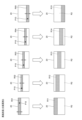
- FIG. 17(a) to (d) are diagrams illustrating schematic diagrams of video signals stored in two first buffers and two second buffers when the first exposure time is longer than the second exposure time in the second embodiment.
- Fig. 18A is a diagram illustrating the generation of a frame image when the first exposure time is longer than the second exposure time according to the second embodiment.
- Fig. 18B is a diagram illustrating an example of a frame image when the first exposure time is longer than the second exposure time according to the second embodiment.
- FIG. 19 is a diagram illustrating a first captured video signal and a second captured video signal acquired by the camera when the first exposure time is shorter than the second exposure time according to the second embodiment.
- Figures 20(a) to (d) are diagrams showing schematic diagrams of video signals stored in two first buffers and two second buffers when the first exposure time is shorter than the second exposure time in embodiment 2.
- Fig. 21A is a diagram illustrating the generation of a frame image when the first exposure time is shorter than the second exposure time according to the second embodiment.
- Fig. 21B is a diagram illustrating an example of a frame image when the first exposure time is shorter than the second exposure time according to the second embodiment.
- FIG. 22 is a flowchart showing a frame image generating process performed by the image generating device according to the second embodiment.
- FIG. 23 is a block diagram showing a configuration of a signal processing unit according to the third embodiment.
- Fig. 24A is a diagram showing a frame image generation according to the third embodiment, and
- Fig. 24B is an example diagram showing a frame image according to the third embodiment.
- FIG. 25 is a block diagram showing a configuration of a signal processing unit according to another modification.
- the present invention is applied to an image generating device for a head mounted display.
- head mounted displays include AR glasses, AR goggles, VR glasses, and VR goggles.
- the head mounted display in the following embodiment is AR glasses.
- the following embodiment is one embodiment of the present invention, and the present invention is not limited to the following embodiment.
- the present invention is not limited to image generating devices for head mounted displays, but can also be applied to image generating devices such as in-vehicle head-up displays.
- the mutually orthogonal X, Y, and Z axes are indicated in addition to the front, back, left, right, up, and down directions of the AR glasses 1.
- the positive X-axis, positive Y-axis, and positive Z-axis directions correspond to the right, rear, and upward directions of the AR glasses 1, respectively.
- the AR glasses 1 include a frame 2, a pair of image generating devices 3, and a pair of mirrors 4.
- the AR glasses 1 are worn on the user's head, similar to regular eyeglasses.
- the frame 2 holds a pair of image generating devices 3 and a pair of mirrors 4.
- the frame 2 is composed of a front portion 2a and a pair of support portions 2b.
- the pair of support portions 2b extend rearward from the right and left ends of the front portion 2a.
- the front portion 2a is positioned in front of a pair of eyes E of the user.
- the frame 2 is composed of an opaque material.
- the frame 2 may also be composed of a transparent material.
- the pair of image generating devices 3 are symmetrical with respect to the Y-Z plane that passes through the center of the AR glasses 1.
- the image generating devices 3 generate an image at the eye E of a user who wears the AR glasses 1 on their head.
- Mirror 4 is a mirror with a concave reflective surface, and is installed on the inner surface of the front portion 2a of the frame 2. Mirror 4 almost completely reflects the light projected from the corresponding projection portion 11, and guides it to the user's eye E.
- the image generating device 3 includes a projection unit 11, a detection unit 12, and a camera 13.
- the projection unit 11 is installed on the inner surface of the support unit 2b.
- the projection unit 11 projects light modulated by a video signal onto the corresponding mirror 4.
- the light from the projection unit 11 reflected by the mirror 4 is irradiated onto the fovea centralis, which is located at the center of the retina in the eye E. This allows the user to visually grasp the frame image 20 (see Figure 2) generated by the image generation device 3.
- the pair of detection units 12 are installed on the inner surface of the front surface 2a between the pair of mirrors 4.
- the detection units 12 are used to detect the user's line of sight.
- the pair of cameras 13 are installed on the outer surface of the front part 2a, in front of the pair of mirrors 4.
- the cameras 13 capture the field of view of the cameras 13.
- the field of view of the cameras 13 is in front of the AR glasses 1.
- FIG. 2 is a diagram showing a schematic configuration of the projection unit 11.
- Light sources 101, 102, and 103 are, for example, semiconductor laser light sources.
- Light source 101 emits laser light with a red wavelength in the range of 635 nm to 645 nm
- light source 102 emits laser light with a green wavelength in the range of 510 nm to 530 nm
- light source 103 emits laser light with a blue wavelength in the range of 440 nm to 460 nm.
- a color image is generated as the frame image 20 described below, so the projection unit 11 is equipped with light sources 101, 102, and 103 capable of emitting red, green, and blue laser light.
- the projection unit 11 may be equipped with only one light source corresponding to the color of the image.
- the projection unit 11 may also be configured to be equipped with two light sources with different emission wavelengths.
- Mirror 131 almost completely reflects the red light that passes through aperture 121.
- Dichroic mirror 132 reflects the green light that passes through aperture 122 and transmits the red light reflected by mirror 131.
- Dichroic mirror 133 reflects the blue light that passes through aperture 123 and transmits the red and green light that passes through dichroic mirror 132.
- Mirror 131 and the two dichroic mirrors 132 and 133 are positioned so as to align the optical axes of the light of each color emitted from light sources 101, 102, and 103.
- the first scanning unit 140 reflects the light that has passed through the dichroic mirror 133.
- the first scanning unit 140 is, for example, a MEMS (Micro Electro Mechanical System) mirror.
- the first scanning unit 140 has a configuration for rotating the first mirror 141, on which the light that has passed through the dichroic mirror 133 is incident, around an axis 141a parallel to the Z-axis direction in response to a drive signal.
- the rotation of the first mirror 141 changes the reflection direction of the light.
- the light reflected by the first mirror 141 is scanned along a scanning line extending in the X-axis direction on the retina of the eye E, as described below.
- the relay optical system 150 directs the light reflected by the first scanning unit 140 toward the center of the second mirror 161 of the second scanning unit 160. That is, the light incident on the first scanning unit 140 is deflected by the first mirror 141 at a predetermined deflection angle.
- the relay optical system 150 directs the light at each deflection angle toward the center of the second mirror 161.
- the relay optical system 150 also has multiple mirrors, and reflects the light reflected by the first scanning unit 140 by the multiple mirrors and directs it toward the second scanning unit 160. This makes it possible to realize a long optical path length inside the relay optical system 150 and suppress the deflection angle of the light when viewed from the second mirror 161.
- the second scanning unit 160 reflects the light that has passed through the relay optical system 150.
- the second scanning unit 160 is, for example, a MEMS mirror.
- the second scanning unit 160 has a configuration that rotates the second mirror 161, on which the light that has passed through the relay optical system 150 is incident, around an axis 161a parallel to the XY plane in response to a drive signal.
- the direction in which the light is reflected changes as the second mirror 161 rotates.
- the scanning line on the retina of the eye E along which the light is scanned by the first scanning unit 140 is changed in the Z-axis direction as described below.
- the light reflected by the second scanning unit 160 i.e., the light emitted from the projection unit 11, is reflected by the mirror 4 and forms a frame image 20 on the retina of the eye E.
- FIG. 3 is a block diagram showing the configuration of the projection unit 11 and the detection unit 12.
- the detection unit 12 includes a light source 12a and an image sensor 12b, and is connected to the control unit 201 of the projection unit 11.
- the light source 12a is, for example, an LED that emits light of an infrared wavelength.
- the image sensor 12b is, for example, a CMOS image sensor or a CCD image sensor.
- the light source 12a irradiates light onto the user's eye E in response to instructions from the control unit 201.
- the image sensor 12b captures an image of the user's eye E in response to instructions from the control unit 201, and outputs the captured image to the control unit 201.
- the camera 13 In response to instructions from the control unit 201, the camera 13 captures an image of its field of view, generates a video signal, and outputs the generated video signal to the signal processing unit 300 of the corresponding projection unit 11.
- the left camera 13 outputs the generated video signal to the signal processing unit 300 of the left projection unit 11
- the right camera 13 outputs the generated video signal to the signal processing unit 300 of the right projection unit 11.
- the camera 13 of embodiment 1 outputs a first captured video signal for high resolution and a second captured video signal for low resolution, as described below.
- the projection unit 11 includes a control unit 201, a first mirror drive circuit 211, a second mirror drive circuit 212, a first mirror monitor sensor 213, a second mirror monitor sensor 214, a signal processing unit 300, a line memory 221, and a laser drive circuit 222.
- the control unit 201 includes an arithmetic processing unit such as a CPU or FPGA, and memory.
- the control unit 201 detects the user's line of sight based on the captured image from the detection unit 12, for example, by the dark pupil method, the bright pupil method, or the corneal reflex method.
- the control unit 201 acquires the viewpoint position in the frame image 20 formed on the user's retina based on the detected line of sight of the user.
- the control unit 201 also controls the signal processing unit 300 to process video signals from the camera 13 and external devices.
- the first mirror drive circuit 211 drives the first mirror 141 of the first scanning unit 140 in response to a drive signal from the control unit 201.
- the second mirror drive circuit 212 drives the second mirror 161 of the second scanning unit 160 in response to a drive signal from the control unit 201.
- the first mirror monitor sensor 213 is installed on the first mirror 141 and outputs a detection signal corresponding to the rotation of the first mirror 141 to the control unit 201.
- the second mirror monitor sensor 214 is installed on the second mirror 161 and outputs a detection signal corresponding to the rotation of the second mirror 161 to the control unit 201. Based on the detection signals from the first mirror monitor sensor 213 and the second mirror monitor sensor 214, the control unit 201 outputs drive signals to the first mirror drive circuit 211 and the second mirror drive circuit 212 so that the first mirror 141 and the second mirror 161 rotate with the desired drive waveform.
- the signal processing unit 300 processes the video signals from the camera 13 and external devices, and generates one line's worth of video signals. The configuration of the signal processing unit 300 will be described later with reference to FIG. 4.
- the line memory 221 outputs one line's worth of video signals output from the signal processing unit 300 to the laser driving circuit 222.
- the laser driving circuit 222 drives the light sources 101, 102, and 103 to emit light modulated by the one line's worth of video signals output from the line memory 221.
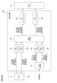
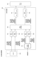
- FIG. 4 is a block diagram showing the configuration of the signal processing unit 300.
- the signal processing unit 300 includes a first buffer 301, a second buffer 302, an input processing unit 310, a first buffer 321, a second buffer 322, a signal synthesis unit 330, a first frame buffer 341, and a second frame buffer 342.
- the imaging processing unit 230 is composed of the camera 13.
- the camera 13 captures an image of the field of view and generates a first imaging video signal for high resolution and a second imaging video signal for low resolution.
- the first buffer 301 is a memory that temporarily stores the first imaging video signal output from the camera 13 (imaging processing unit 230).
- the second buffer 302 is a memory that temporarily stores the second imaging video signal output from the camera 13 (imaging processing unit 230).
- FIG. 5 is a diagram showing a schematic diagram of the first and second image capture signals acquired by the camera 13.
- Camera 13 generates a first imaging video signal in a first imaging period set within one frame, and generates a second imaging video signal in a second imaging period different from the first imaging period within one frame.
- the first imaging period is the first half of one frame
- the second imaging period is the second half of one frame
- the lengths of the first imaging period and the second imaging period are the same.
- the video signals for each line stored in the first buffer 301 and the second buffer 302 are shown by solid and dashed lines.
- the odd-numbered first captured video signals from the top are shown by solid lines
- the even-numbered first captured video signals from the top are shown by dashed lines.
- 17 lines of first captured video signals are shown in the first buffer 301 in FIG. 5, but the actual number of lines is several levels more.
- the second captured video signals stored in the second buffer 302 the second captured video signals with the dashed lines of the first buffer 301 omitted are shown by solid lines.
- the second imaging video signal of the second buffer 302 is a signal in which every other line of the first imaging video signal of the first buffer 301 is thinned out by driving each light receiving unit in the camera 13.
- the manner in which the lines are thinned out is not limited to this, and for example, the second imaging video signal of the second buffer 302 may be a signal in which every third or more lines of the first imaging video signal of the first buffer 301 are thinned out.
- the video signal from the external device is, for example, a video signal related to CG (Computer Graphics). This video signal has the same resolution as the first captured video signal output from camera 13.
- Input processing unit 310 performs thinning processing on the video signal input from the external device.
- First buffer 321 is a memory that temporarily stores the video signal input from the external device, i.e., the first input video signal that has not been thinned out by input processing unit 310.
- Second buffer 322 is a memory that temporarily stores the second input video signal after thinning processing by input processing unit 310.
- FIG. 6 is a schematic diagram for explaining the thinning process performed by the input processing unit 310.
- the input processing unit 310 generates a first input video signal and a second input video signal, each having a different resolution, from a video signal from an external device.
- the video signals for each line stored in the first buffer 321 and the second buffer 322 are shown by solid and dashed lines.
- the odd-numbered first input video signals from the top are shown by solid lines
- the even-numbered first input video signals from the top are shown by dashed lines.
- 17 lines of first input video signals are shown in the first buffer 321 in FIG. 6, but the actual number of lines is several lines more.
- the second input video signal stored in the second buffer 322 is a signal in which the dashed lines of the first buffer 321 have been thinned out.
- the second input video signal of the second buffer 322 is a signal in which every other line of the first input video signal of the first buffer 321 is thinned out.
- the manner in which the lines are thinned out is not limited to this, and for example, the second input video signal may be a signal in which every third or more lines of the first input video signal of the first buffer 321 are thinned out.
- the second input video signal may be generated by mixing adjacent lines of the first input video signal stored in the first buffer 321. In the mixing process, for example, two adjacent lines are replaced with one line calculated as the average value of the signals of these two lines.
- the signal synthesis unit 330 synthesizes the first captured video signal for high resolution stored in the first buffer 301 and the first input video signal for high resolution stored in the first buffer 321 to generate a first synthesized video signal for high resolution for one frame.
- the signal synthesis unit 330 also synthesizes the second captured video signal for low resolution stored in the second buffer 302 and the second input video signal for low resolution stored in the second buffer 322 to generate a second synthesized video signal for low resolution for one frame.
- the first frame buffer 341 stores one frame of the first composite video signal for high resolution generated by the signal synthesis unit 330.
- the second frame buffer 342 stores one frame of the second composite video signal for low resolution generated by the signal synthesis unit 330.
- the first frame buffer 34 in response to a control signal from the control unit 201 (see FIG. 3), sequentially outputs one line of the first composite video signal of one stored frame of the first composite video signal to the line memory 221.
- the second frame buffer 342 in response to a control signal from the control unit 201, sequentially outputs one line of the second composite video signal of one stored frame of the second composite video signal to the line memory 221. Either one of the one line of the first composite video signal from the first frame buffer 341 or the one line of the second composite video signal from the second frame buffer 342 is input to the line memory 221.
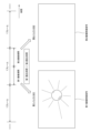
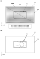
- FIG. 7(a) is a schematic diagram showing the generation of a frame image 20 according to a comparative example.
- the resolution (number of scanning lines) of the frame image 20 is set low in the outer area of a predetermined range including the user's viewpoint position P10, as shown in FIG. 7(b). This makes it less likely that the user's eyes will become tired.
- a first composite video signal with a large number of scanning lines (high resolution) is stored in advance in the first frame buffer 341, and a second composite video signal with a small number of scanning lines (low resolution) is stored in the second frame buffer 342.
- the control unit 201 then switches between the first composite video signal from the first frame buffer 341 and the second composite video signal from the second frame buffer 342 according to the viewpoint position P10 to generate the frame image 20. This makes it possible to suppress the above-mentioned display delay and realize image generation that tracks the user's viewpoint position P10.
- FIG. 7(b) is a diagram showing a schematic diagram of the generation of a frame image 20 according to the first embodiment.
- the control unit 201 detects the user's line of sight based on the captured image acquired by the detection unit 12, and acquires the viewpoint position P10 on the frame image 20 based on the detected line of sight.
- the control unit 201 controls the light sources 101, 102, 103, the first scanning unit 140, and the second scanning unit 160 so that an image is generated by applying a high-resolution first composite video signal from the first frame buffer 341 to a first image region R1 of a predetermined number of scanning lines that includes the viewpoint position P10 on the frame image 20.
- the control unit 201 also controls the light sources 101, 102, 103, the first scanning unit 140, and the second scanning unit 160 so that an image is generated by applying a low-resolution second composite video signal from the second frame buffer 342 to a second image region R2 other than the first image region R1 of the frame image 20.
- FIG. 7(b) for convenience, about five scanning lines are shown in the first image region R1, and about eight scanning lines in total are shown in the second image region R2, but the actual number of scanning lines is several levels more.
- the number of scanning lines included in the first image region R1 may be changed as appropriate. Also, in FIG. 7(b), the first image region R1 has ranges with the same number of scanning lines above and below the viewpoint position P10 as the center, but the number of scanning lines corresponding to the upper range and the number of scanning lines corresponding to the lower range may be different from each other.
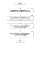
- FIG. 8 is a flowchart showing the process of generating a frame image 20 performed by the image generating device 3.
- the processing in steps S11 to S19 is related to the generation of a frame image 20 corresponding to one frame.
- the control unit 201 performs a storage process (S11). As a result, a first composite video signal for one frame of high resolution and a second composite video signal for one frame of low resolution are stored in the first frame buffer 341 and the second frame buffer 342, respectively, based on the video signal from the camera 13 and the video signal from the external device.
- FIG. 9 is a flowchart showing the details of the storage process of step S11 in FIG. 8. The process in FIG. 9 is executed by the control unit 201 controlling the imaging processing unit 230 and the signal processing unit 300.
- the imaging processor 230 (camera 13 in the first embodiment) generates a first imaging video signal for high resolution during the first imaging period, and generates a second imaging video signal for low resolution during the second imaging period.
- the imaging processor 230 then stores the generated first imaging video signal and second imaging video signal in the first buffer 301 and second buffer 302, respectively (S101).
- the input processing unit 310 generates a first input video signal for high resolution and a second input video signal for low resolution based on a video signal input from an external device. Then, the input processing unit 310 stores the generated first input video signal and second input video signal in the first buffer 321 and the second buffer 322, respectively (S102). Note that the processes of steps S101 and S102 are performed in parallel.
- the signal synthesis unit 330 synthesizes the first captured video signal stored in the first buffer 301 with the first input video signal of the same line as the first captured video signal among the first input video signals stored in the first buffer 321, to generate a first synthesized video signal for one frame of high resolution.
- the signal synthesis unit 330 then stores the generated first synthesized video signal in the first frame buffer 341 (S103).
- the signal synthesis unit 330 synthesizes the second captured video signal stored in the second buffer 302 with the second input video signal of the same line as the second captured video signal among the second input video signals stored in the second buffer 322, to generate a second synthesized video signal for one frame of low resolution.
- the signal synthesis unit 330 then stores the generated second synthesized video signal in the second frame buffer 342 (S104). Note that the processes of steps S103 and S104 are performed in parallel.
- the control unit 201 detects the user's viewpoint position P10 based on the captured image acquired by the detection unit 12 (S12).
- the control unit 201 sets the first image area R1 and the second image area R2 based on the viewpoint position P10 detected in step S12 (S13).
- the control unit 201 causes the first frame buffer 341 to output a high-resolution first composite video signal to the line memory 221 (S15). As a result, one line of image is generated by the first composite video signal from the first frame buffer 341. In parallel with this, the control unit 201 controls the second mirror drive circuit 212 so that the second mirror 161 rotates at the first scanning speed (S16). As a result, the spacing between vertically adjacent scan lines becomes narrower, as shown in the first image region R1 in FIG. 7(b).
- the control unit 201 causes the second frame buffer 342 to output a low-resolution second composite video signal to the line memory 221 (S17). As a result, one line of image is generated by the second composite video signal from the second frame buffer 342.
- the control unit 201 controls the second mirror drive circuit 212 so that the second mirror 161 rotates at a second scanning speed that is faster than the first scanning speed (S18). As a result, the spacing between vertically adjacent scanning lines becomes wider, as shown in the second image region R2 in FIG. 7(b).
- the control unit 201 determines whether or not image generation for one frame has been completed (S19). If image generation for one frame has not been completed (S19: NO), the process returns to step S12, and steps S12 to S18 are performed again. When image generation for one frame is completed in this manner (S19: YES), the process in FIG. 8 ends. Frame images 20 are generated continuously by repeating the process in FIG. 8.
- the camera 13 of this modified example outputs only a high-resolution video signal similar to the first captured video signal of embodiment 1.
- the input processing unit 350 performs a thinning process on the video signal input from the camera 13 similar to the thinning process performed by the input processing unit 310.
- the first buffer 301 temporarily stores the first captured video signal output from the camera 13 that has not been thinned out by the input processing unit 350.
- the second buffer 302 temporarily stores the second captured video signal that has been thinned out and generated by the input processing unit 350.
- the second imaging video signal in the second buffer 302 is a signal in which every other line of the first imaging video signal in the first buffer 301 is thinned out.
- the manner in which the lines are thinned out is not limited to this, and for example, the second imaging video signal may be a signal in which every third or more lines of the first imaging video signal in the first buffer 301 are thinned out.
- the second imaging video signal may be generated by mixing adjacent lines of the first imaging video signal stored in the first buffer 301. In the mixing process, for example, two adjacent lines are replaced with one line calculated as the average value of the signals of these two lines.
- the camera 13 only needs to output one type of first imaging video signal, and therefore the configuration and processing of the camera 13 can be simplified. Furthermore, as shown in the first embodiment, in a configuration in which the first imaging video signal and the second imaging video signal are obtained in two different imaging periods, if the subject moves at high speed, the position of the subject will differ in the two types of video signals. However, according to this modified example, since the camera 13 only outputs one type of first imaging video signal, the position of the subject will be the same in the first imaging video signal and the second imaging video signal generated by the input processing unit 350, even if the subject moves at high speed. This makes it possible to avoid any discomfort felt by the user based on the first imaging video signal and the second imaging video signal.
- the signal processing unit 300 in FIG. 12 omits the input processing unit 310, the first buffer 321, the second buffer 322, and the signal synthesis unit 330.
- the first captured video signal from the camera 13 is temporarily stored in the first buffer 301, and one frame of the first captured video signal is then output to the first frame buffer 341.
- the second captured video signal from the camera 13 is temporarily stored in the second buffer 302, and one frame of the second captured video signal is then output to the second frame buffer 342.
- the first captured video signal stored in the first frame buffer 341 and the second captured video signal stored in the second frame buffer 342 are selectively used according to the user's line of sight to generate one frame of image. Therefore, similar to the first embodiment, the image resolution (definition) can be smoothly switched between the first image region R1 near the user's line of sight and the other second image region R2.
- control unit 201 sets regions R11 to R15 as the first image region, respectively.
- Viewpoint regions R01 to R05 are obtained by dividing frame image 20 into five regions in the vertical direction (Z-axis direction).
- Regions R11 to R15 are regions set corresponding to viewpoint regions R01 to R05, and each includes a predetermined number of scanning lines.
- regions R11 to R15 are set as the first image region, regions other than regions R11 to R15 are set as the second image region, respectively.
- FIG. 14 shows the scanning speed of the second mirror 161 when the five regions R11 to R15 are each set as the first image region in this modified example.
- the scanning speed of the second mirror 161 is set as shown in the bottom graph of FIG. 14.
- the bottom graph of FIG. 14 shows the scanning speed of the second mirror 161 for scanning one line.
- the speed of the second mirror 161 is slower in regions R11 to R15.
- the control unit 201 sets the area including the viewpoint position P10 as the first image area out of a plurality of areas R11 to R15 that are previously formed by dividing the frame image 20 in a direction (Z-axis direction) that intersects with the scanning lines.
- the camera 13 of the first embodiment outputs two types of video signals, a first captured video signal for high resolution and a second captured video signal for low resolution, whereas the camera 13 of the second embodiment outputs two types of video signals, a first captured video signal for a first luminance and a second captured video signal for a second luminance.
- FIG. 15 is a block diagram showing the configuration of the signal processing unit 300 according to the second embodiment.
- the signal processing unit 300 in FIG. 15 differs in the two types of video signals output from the camera 13. That is, the camera 13 outputs a first imaged video signal for a first luminance and a first imaged video signal for a second luminance.
- the signal synthesis unit 330 synthesizes the first imaged video signal for a first luminance stored in the first buffer 301 with the first input video signal for high resolution stored in the first buffer 321 to generate a first synthesized video signal for the first luminance and high resolution for one frame.
- the signal synthesis unit 330 also synthesizes the second imaged video signal for a second luminance stored in the second buffer 302 with the second input video signal for low resolution stored in the second buffer 322 to generate a second synthesized video signal for the second luminance and low resolution for one frame.
- the control unit 201 sets a first image region R31 of a predetermined size including the viewpoint position P10.
- the first image region R31 corresponds to the user's visual field range of, for example, ⁇ 30° in the X-axis direction and ⁇ 10° in the Z-axis direction, with the viewpoint position P10 as the center.
- the control unit 201 applies a first composite video signal from the first frame buffer 341 to the first image region R31 including the viewpoint position P10, and causes light to be emitted from the light sources 101, 102, and 103.
- the control unit 201 applies a second composite video signal from the second frame buffer 342 to the second image region R32 other than the first image region R31, and causes light to be emitted from the light sources 101, 102, and 103.
- FIG. 19 is a diagram showing a schematic diagram of the first and second captured video signals acquired by the camera 13 when the first exposure time is shorter than the second exposure time.
- the first exposure time is shorter than the second exposure time, compared to the example shown in FIG. 16.
- the first imaging video signal for the first luminance generated by the first exposure time is darker than the second imaging video signal for the second luminance generated by the second exposure time.
- 20(a) to (d) are schematic diagrams showing the video signals stored in the first buffer 301, the second buffer 302, the first buffer 321, and the second buffer 322, respectively.
- the first buffer 301 stores the first image pickup video signal for the first luminance generated by the camera 13, i.e., in the example of FIG. 19, the dark first image pickup video signal.
- the second buffer 302 stores the second image pickup video signal for the second luminance generated by the camera 13, i.e., in the example of FIG. 19, the bright second image pickup video signal.
- the first buffer 321 stores the first input video signal for high resolution
- the second buffer 322 stores the second input video signal for low resolution.
- the signal synthesis unit 330 synthesizes the first captured image signal as shown in Fig. 20(a) with the first input image signal as shown in Fig. 20(c) to generate a first synthesized image signal for the first luminance and high resolution.
- the signal synthesis unit 330 also synthesizes the second captured image signal as shown in Fig. 20(b) with the second input image signal as shown in Fig. 20(d) to generate a second synthesized image signal for the second luminance and low resolution.
- control unit 201 also sets a first image region R31 similar to that shown in FIG. 18(a), and applies the first composite video signal from the first frame buffer 341 to the first image region R31 including the viewpoint position P10.
- the control unit 201 also applies the second composite video signal from the second frame buffer 342 to the second image region R32 other than the first image region R31.
- the control unit 201 If the current scan line is included only in the second image region R32 (S21: YES), the control unit 201 outputs the second composite video signal from the second frame buffer 342 to the line memory 221 (S22). As a result, in the second embodiment, one line of an image is generated by the second composite video signal for the second luminance and low resolution.
- the imaging processing section 230 outputs a first imaging video signal for constructing a frame image 20 of a first luminance (first resolution) and a second imaging video signal for constructing a frame image 20 of a second luminance (second resolution).
- the first frame buffer 341 stores the first composite video signal (first imaging video signal)
- the second frame buffer 342 stores the second composite video signal (second imaging video signal).
- the signal synthesis unit 330 synthesizes the first captured image signal for high gradation stored in the first buffer 301 and the first input image signal for high gradation stored in the first buffer 321 to generate a first synthesized image signal for high gradation for one frame.
- the signal synthesis unit 330 also synthesizes the second captured image signal for low gradation stored in the second buffer 302 and the second input image signal for low gradation stored in the second buffer 322 to generate a second synthesized image signal for low gradation for one frame.
- FIG. 24(a) is a diagram showing a schematic diagram of the generation of a frame image 20 according to embodiment 3.
- the imaging processing unit 230 outputs a first imaging video signal for constructing a high gradation (first definition) frame image 20 and a second imaging video signal for constructing a low gradation (second definition) frame image 20.
- the first frame buffer 341 stores the first composite video signal (first imaging video signal)
- the second frame buffer 342 stores the second composite video signal (second imaging video signal).
- the first captured video signal stored in the first frame buffer 341 and the second captured video signal stored in the second frame buffer 342 are selectively used according to the user's line of sight to generate one frame of image. This allows smooth switching of the image gradation (resolution) between the first image region R31 near the user's line of sight and the other second image region R32.
- a high-gradation frame image 20 is displayed in the first image region R31 near the user's line of sight, and a low-gradation frame image 20 is displayed in the second image region R32 around the user's line of sight. This makes it possible to reduce eye fatigue for the user. Furthermore, even if the user has poor eyesight, the user can clearly grasp the subject by referring to the high-gradation frame image 20 in the first image region R31.
- the camera 13 outputs a first captured video signal corresponding to a high gradation (first gradation), and the imaging processing unit 230 has an input processing unit 350 that performs processing to reduce the gradation of the high gradation first captured video signal to generate a second captured video signal for a low gradation (second gradation).
- This configuration allows for smooth generation of high and low gradation video signals.
- the input processing unit 350 may be configured integrally with the camera 13.
- the video signal from the external device may be a first input video signal for high gradation and a second input video signal for low gradation. In this case, the input processing unit 310 is omitted.
- the configuration for processing video signals from an external device i.e., the input processing unit 310, the first buffer 321, the second buffer 322, and the signal synthesis unit 330, may be omitted.
- FIG. 25 is a block diagram showing the configuration of the signal processing unit 300 in this modified example.
- the detection of the viewpoint position P10 and the setting of the first image area and the second image area are performed for each line of image generation, but they may also be performed for each frame of image (frame image 20) generation.
- the input processing unit 350 performs thinning and mixing processes on the input first imaging video signal for high resolution to generate a second imaging video signal for low resolution, as shown in FIG. 11.
- the input processing unit 350 may perform complementation processes on the input second imaging video signal for low resolution to generate a first imaging video signal for high resolution.
- complementation processes impose a higher processing load than thinning and mixing processes, it is preferable that the video signal input to the input processing unit 350 is the first imaging video signal for high resolution.
- the input processing units 350 and 310 perform processing to reduce the number of gradations of the video signal to two gradations, but this is not limited thereto, and processing to reduce the number of gradations of the video signal to a number other than two gradations (for example, 16 gradations) may also be performed.
- two frame buffers the first frame buffer 341 and the second frame buffer 342, are used, but three or more frame buffers storing video signals with different definitions (resolution, brightness, gradation, combinations thereof, etc.) may be used to output video signals to the line memory 221.
- two of the three or more frame buffers are selected as the first frame buffer 341 and the second frame buffer 342 to process the image display. Which of the three or more frame buffers is used to generate the display image is selected, for example, by the user.
- three buffers are provided between the input processing unit 350 and the signal synthesis unit 330 for temporarily storing the captured image video signals of the three levels of definition
- three buffers are provided between the input processing unit 310 and the signal synthesis unit 330 for temporarily storing the input image signals of the three levels of definition.
- the signal synthesis unit 330 then synthesizes the captured image video signals and the input video signals of the corresponding levels of definition, and outputs the synthesized synthesized video signals of the three levels of definition to the corresponding frame buffers.
- An imaging processing section including a camera for imaging a field of view, and outputting a first imaging video signal for constructing a frame image of a first resolution and a second imaging video signal for constructing a frame image of a second resolution different from the first resolution; a first frame buffer for storing the first image pickup video signal; a second frame buffer for storing the second image signal; a light source that emits light for constructing the frame image; A scanning unit that scans the light emitted from the light source; A detection unit for detecting a line of sight of a user; A control unit, The control unit is controlling the light source and the scanning unit so that an image is generated by applying the first captured video signal from the first frame buffer to a first image region including a viewpoint position on the frame image corresponding to the line of sight; controlling the light source and the scanning unit so that an image is generated by applying the second captured video signal from the second frame buffer to a second image area other than the first image area of the frame image; 1.
- An image generating apparatus comprising:
- the first definition and the second definition are a first resolution and a second resolution of the frame image defined by a scanning speed of the scanning unit, respectively;
- the first resolution is higher than the second resolution.
Landscapes
- Engineering & Computer Science (AREA)
- Physics & Mathematics (AREA)
- General Physics & Mathematics (AREA)
- Computer Hardware Design (AREA)
- Theoretical Computer Science (AREA)
- Optics & Photonics (AREA)
- Multimedia (AREA)
- Signal Processing (AREA)
- Control Of Indicators Other Than Cathode Ray Tubes (AREA)
Abstract
This image generation device comprises: an imaging processing unit (230) that includes a camera (13) for imaging a field-of-view range and that outputs a first imaged video signal for forming a frame image having a first definition and a second imaged video signal for forming a frame image having a second definition; and a first frame buffer (341) that stores the first imaged video signal therein and a second frame buffer (342) that stores the second imaged video signal therein. An image is generated in a first image area by applying the first imaged video signal from the first frame buffer (341), and an image is generated in a second image area by applying the second imaged video signal from the second frame buffer (342).
Description
本発明は、光を走査して画像を生成する画像生成装置およびヘッドマウントディスプレイに関する。
The present invention relates to an image generating device and a head-mounted display that generate images by scanning light.
従来、光を走査して画像を生成する画像生成装置として、たとえば、AR(Augmented Reality)やVR(Virtual Reality)を実現するゴーグルやグラスなどのヘッドマウントディスプレイが知られている。これらの装置では、たとえば、映像信号に基づく光が半透明のディスプレイに向けて照射され、その反射光がユーザの目に照射される。あるいは、映像信号に基づく光がユーザの目に直接照射される。
Conventionally, known image generating devices that generate images by scanning light include head-mounted displays such as goggles and glasses that realize AR (Augmented Reality) and VR (Virtual Reality). In these devices, for example, light based on a video signal is directed toward a translucent display, and the reflected light is directed toward the user's eyes. Alternatively, light based on a video signal is directly directed toward the user's eyes.
以下の特許文献1には、MEMSミラーのファスト軸およびスロー軸の回転を制御することにより、画像の第1の部分において第1の線密度を実現し、画像の第2の部分において第1の線密度よりも低い第2の線密度を実現し、目の視線に基づいて画像の第1の部分の位置を決定する装置が記載されている。これにより、視線に対応しない第2の部分の画像の解像度が、視線に対応する第1の部分の画像の解像度より低くなるため、使用者の目が疲れにくくなる。
The following Patent Document 1 describes an apparatus that realizes a first line density in a first portion of an image and a second line density lower than the first line density in a second portion of the image by controlling the rotation of the fast axis and slow axis of a MEMS mirror, and determines the position of the first portion of the image based on the line of sight of the eye. As a result, the resolution of the image in the second portion that does not correspond to the line of sight is lower than the resolution of the image in the first portion that corresponds to the line of sight, reducing eye fatigue for the user.
上記のようなヘッドマウントディスプレイでは、画像生成用の光を変調するための映像信号として、たとえば、使用者前方の画像を撮像して得られた映像信号を用いることができる。これにより、上述のゴーグルやグラスが特にシースルーでなくても、使用者は、撮像された画像から前方の風景を把握できる。
In a head-mounted display like the one described above, for example, a video signal obtained by capturing an image in front of the user can be used as a video signal for modulating the light used to generate the image. This allows the user to grasp the scenery in front of them from the captured image, even if the goggles or glasses described above are not particularly see-through.
この場合、使用者がより快適に画像を見ることができるように、使用者の視線に対応する部分の画像の精細度とその他の部分の画像の精細度とを、互いに相違させることが好ましい。
In this case, it is preferable to make the image definition of the portion of the image corresponding to the user's line of sight different from the image definition of the other portions so that the user can view the image more comfortably.
しかしながら、使用者の視線は動的に変化し得るため、視線に応じて各精細度の映像信号を生成すると、映像信号の生成が間に合わず、表示に遅れが生じてしまう。このような表示遅れが生じると、画像が乱れ、使用者への違和感が生じてしまう。
However, because the user's line of sight can change dynamically, if video signals of each resolution are generated according to the line of sight, the video signals cannot be generated in time, resulting in a delay in display. When such a display delay occurs, the image becomes distorted, causing discomfort to the user.
かかる課題に鑑み、本発明は、使用者の視線付近の第1画像領域とその他の第2画像領域とにおいて画像の精細度を円滑に切り替えることが可能な画像生成装置およびヘッドマウントディスプレイを提供することを目的とする。
In view of these problems, the present invention aims to provide an image generating device and a head-mounted display that can smoothly switch between the image resolution of a first image area near the user's line of sight and a second image area elsewhere.
本発明の第1の態様に係る画像生成装置は、視野範囲を撮像するカメラを含み、第1精細度のフレーム画像を構成するための第1撮像映像信号および前記第1精細度とは異なる第2精細度のフレーム画像を構成するための第2撮像映像信号をそれぞれ出力する撮像処理部と、前記第1撮像映像信号を記憶する第1フレームバッファと、前記第2撮像映像信号を記憶する第2フレームバッファと、前記フレーム画像を構成するための光を出射する光源と、前記光源から出射された光を走査させる走査部と、使用者の視線を検出するための検出部と、制御部と、を備える。前記制御部は、前記視線に対応する前記フレーム画像上の視点位置を含む第1画像領域には、前記第1フレームバッファからの前記第1撮像映像信号を適用して画像が生成されるよう、前記光源および前記走査部を制御し、前記フレーム画像の前記第1画像領域以外の第2画像領域には、前記第2フレームバッファからの前記第2撮像映像信号を適用して画像が生成されるよう、前記光源および前記走査部を制御する。
The image generating device according to the first aspect of the present invention includes a camera that captures an image of a field of view, an imaging processing unit that outputs a first imaging video signal for constructing a frame image of a first resolution and a second imaging video signal for constructing a frame image of a second resolution different from the first resolution, a first frame buffer that stores the first imaging video signal, a second frame buffer that stores the second imaging video signal, a light source that emits light for constructing the frame image, a scanning unit that scans the light emitted from the light source, a detection unit that detects the user's line of sight, and a control unit. The control unit controls the light source and the scanning unit so that an image is generated by applying the first imaging video signal from the first frame buffer to a first image area including a viewpoint position on the frame image corresponding to the line of sight, and controls the light source and the scanning unit so that an image is generated by applying the second imaging video signal from the second frame buffer to a second image area of the frame image other than the first image area.
本態様に係る画像生成装置によれば、第1フレームバッファに記憶された第1撮像映像信号と、第2フレームバッファに記憶された第2撮像映像信号とが、使用者の視線に応じて選択的に用いられて、1フレームの画像が生成される。このため、使用者の視線付近の第1画像領域とその他の第2画像領域とにおいて、画像の精細度を円滑に切り替えることができる。
In the image generating device according to this embodiment, the first captured video signal stored in the first frame buffer and the second captured video signal stored in the second frame buffer are selectively used according to the user's line of sight to generate one frame of image. This allows smooth switching of image resolution between the first image area near the user's line of sight and the other second image area.
本発明の第2の態様に係るヘッドマウントディスプレイは、第1の態様に係る画像生成装置と、前記画像生成装置を保持するフレームと、前記画像生成装置からの光を、当該ヘッドマウントディスプレイを頭部に装着した前記使用者の目に導くための光学系と、を備える。
The head mounted display according to the second aspect of the present invention comprises the image generating device according to the first aspect, a frame that holds the image generating device, and an optical system that guides light from the image generating device to the eyes of the user who wears the head mounted display on his or her head.
本態様に係るヘッドマウントディスプレイによれば、第1の態様と同様の効果が奏される。また、使用者は、ヘッドマウントディスプレイを頭部に装着することにより、カメラにより撮像された風景等を、画像生成装置により生成されたフレーム画像により把握できる。
The head mounted display of this embodiment provides the same effects as the first embodiment. In addition, by wearing the head mounted display on the head, the user can grasp the scenery captured by the camera through the frame image generated by the image generating device.
以上のとおり、本発明によれば、使用者の視線付近の第1画像領域とその他の第2画像領域とにおいて画像の精細度を円滑に切り替えることが可能な画像生成装置およびヘッドマウントディスプレイを提供できる。
As described above, the present invention provides an image generating device and a head mounted display that can smoothly switch between the image resolution of a first image area near the user's line of sight and a second image area elsewhere.
本発明の効果ないし意義は、以下に示す実施形態の説明により更に明らかとなろう。ただし、以下に示す実施形態は、あくまでも、本発明を実施化する際の一つの例示であって、本発明は、以下の実施形態に記載されたものに何ら制限されるものではない。
The effects and significance of the present invention will become clearer from the description of the embodiment shown below. However, the embodiment shown below is merely an example of how the present invention may be put into practice, and the present invention is in no way limited to the embodiment described below.
ただし、図面はもっぱら説明のためのものであって、この発明の範囲を限定するものではない。
However, the drawings are for illustrative purposes only and do not limit the scope of the invention.
以下、本発明の実施形態について図面を参照して説明する。以下の実施形態には、ヘッドマウントディスプレイの画像生成装置に本発明を適用した例が示されている。ヘッドマウントディスプレイとして、ARグラス、ARゴーグル、VRグラス、VRゴーグルなどが挙げられる。以下の実施形態のヘッドマウントディスプレイは、ARグラスである。ただし、以下の実施形態は、本発明の一実施形態あって、本発明は、以下の実施形態に何ら制限されるものではない。たとえば、本発明は、ヘッドマウントディスプレイの画像生成装置に限らず、車載のヘッドアップディスプレイなどの画像生成装置にも適用可能である。
Below, an embodiment of the present invention will be described with reference to the drawings. In the following embodiment, an example is shown in which the present invention is applied to an image generating device for a head mounted display. Examples of head mounted displays include AR glasses, AR goggles, VR glasses, and VR goggles. The head mounted display in the following embodiment is AR glasses. However, the following embodiment is one embodiment of the present invention, and the present invention is not limited to the following embodiment. For example, the present invention is not limited to image generating devices for head mounted displays, but can also be applied to image generating devices such as in-vehicle head-up displays.
<実施形態1>
図1は、ARグラス1の構成を模式的に示す斜視図である。 <Embodiment 1>
FIG. 1 is a perspective view showing a schematic configuration of theAR glasses 1.
図1は、ARグラス1の構成を模式的に示す斜視図である。 <
FIG. 1 is a perspective view showing a schematic configuration of the
図1には、ARグラス1の前後左右上下方向とともに、互いに直交するX、Y、Z軸が付記されている。X軸正方向、Y軸正方向およびZ軸正方向は、それぞれ、ARグラス1の右方向、後ろ方向および上方向に対応する。
In FIG. 1, the mutually orthogonal X, Y, and Z axes are indicated in addition to the front, back, left, right, up, and down directions of the AR glasses 1. The positive X-axis, positive Y-axis, and positive Z-axis directions correspond to the right, rear, and upward directions of the AR glasses 1, respectively.
ARグラス1は、フレーム2と、一対の画像生成装置3と、一対のミラー4と、を備える。ARグラス1は、一般的な眼鏡と同様、使用者の頭部に装着される。
The AR glasses 1 include a frame 2, a pair of image generating devices 3, and a pair of mirrors 4. The AR glasses 1 are worn on the user's head, similar to regular eyeglasses.
フレーム2は、一対の画像生成装置3および一対のミラー4を保持する。フレーム2は、前面部2aおよび一対の支持部2bにより構成される。一対の支持部2bは、前面部2aの右端および左端から後方に延びている。フレーム2が使用者に装着されると、前面部2aが使用者の一対の目Eの前方に位置付けられる。フレーム2は、不透明な材料により構成される。フレーム2が、透明な材料により構成されてもよい。
The frame 2 holds a pair of image generating devices 3 and a pair of mirrors 4. The frame 2 is composed of a front portion 2a and a pair of support portions 2b. The pair of support portions 2b extend rearward from the right and left ends of the front portion 2a. When the frame 2 is worn by a user, the front portion 2a is positioned in front of a pair of eyes E of the user. The frame 2 is composed of an opaque material. The frame 2 may also be composed of a transparent material.
一対の画像生成装置3は、ARグラス1の中心を通るY-Z平面に対して、互いに線対称である。画像生成装置3は、ARグラス1を頭部に装着した使用者の目Eにおいて画像を生成する。
The pair of image generating devices 3 are symmetrical with respect to the Y-Z plane that passes through the center of the AR glasses 1. The image generating devices 3 generate an image at the eye E of a user who wears the AR glasses 1 on their head.
ミラー4は、反射面が凹状に形成されたミラーであり、フレーム2の前面部2aの内側面に設置される。ミラー4は、対応する投射部11から投射された光を略全反射して、使用者の目Eに導く。
Mirror 4 is a mirror with a concave reflective surface, and is installed on the inner surface of the front portion 2a of the frame 2. Mirror 4 almost completely reflects the light projected from the corresponding projection portion 11, and guides it to the user's eye E.
画像生成装置3は、投射部11と、検出部12と、カメラ13と、を備える。
The image generating device 3 includes a projection unit 11, a detection unit 12, and a camera 13.
投射部11は、支持部2bの内側面に設置される。投射部11は、対応するミラー4に対して、映像信号により変調された光を投射する。ミラー4により反射された投射部11からの光は、目E内の網膜の中心に位置する中心窩に照射される。これにより、使用者は、画像生成装置3により生成されたフレーム画像20(図2参照)を視覚的に把握できる。
The projection unit 11 is installed on the inner surface of the support unit 2b. The projection unit 11 projects light modulated by a video signal onto the corresponding mirror 4. The light from the projection unit 11 reflected by the mirror 4 is irradiated onto the fovea centralis, which is located at the center of the retina in the eye E. This allows the user to visually grasp the frame image 20 (see Figure 2) generated by the image generation device 3.
一対の検出部12は、一対のミラー4の間において、前面部2aの内側面に設置されている。検出部12は、使用者の視線を検出するために用いられる。
The pair of detection units 12 are installed on the inner surface of the front surface 2a between the pair of mirrors 4. The detection units 12 are used to detect the user's line of sight.
一対のカメラ13は、一対のミラー4の前方において、前面部2aの外側面に設置されている。カメラ13は、当該カメラ13の視野範囲を撮像する。本実施形態のカメラ13の視野範囲は、ARグラス1の前方である。
The pair of cameras 13 are installed on the outer surface of the front part 2a, in front of the pair of mirrors 4. The cameras 13 capture the field of view of the cameras 13. In this embodiment, the field of view of the cameras 13 is in front of the AR glasses 1.
図2は、投射部11の構成を模式的に示す図である。
FIG. 2 is a diagram showing a schematic configuration of the projection unit 11.
投射部11は、光源101、102、103と、コリメータレンズ111、112、113と、アパーチャ121、122、123と、ミラー131と、ダイクロイックミラー132、133と、第1走査部140と、リレー光学系150と、第2走査部160と、を備える。
The projection unit 11 includes light sources 101, 102, and 103, collimator lenses 111, 112, and 113, apertures 121, 122, and 123, a mirror 131, dichroic mirrors 132 and 133, a first scanning unit 140, a relay optical system 150, and a second scanning unit 160.
光源101、102、103は、たとえば、半導体レーザ光源である。光源101は、635nm以上645nm以下の範囲に含まれる赤色波長のレーザ光を出射し、光源102は、510nm以上530nm以下の範囲に含まれる緑色波長のレーザ光を出射し、光源103は、440nm以上460nm以下の範囲に含まれる青色波長のレーザ光を出射する。
Light sources 101, 102, and 103 are, for example, semiconductor laser light sources. Light source 101 emits laser light with a red wavelength in the range of 635 nm to 645 nm, light source 102 emits laser light with a green wavelength in the range of 510 nm to 530 nm, and light source 103 emits laser light with a blue wavelength in the range of 440 nm to 460 nm.
実施形態1では、後述するフレーム画像20としてカラー画像が生成されるため、投射部11は、赤色、緑色および青色のレーザ光を出射可能な光源101、102、103を備える。フレーム画像20として単色の画像を表示する場合、投射部11は、画像の色に対応する1つの光源のみを備えていてもよい。また、投射部11は、出射波長の異なる2つの光源を備える構成でもよい。
In the first embodiment, a color image is generated as the frame image 20 described below, so the projection unit 11 is equipped with light sources 101, 102, and 103 capable of emitting red, green, and blue laser light. When a monochromatic image is displayed as the frame image 20, the projection unit 11 may be equipped with only one light source corresponding to the color of the image. The projection unit 11 may also be configured to be equipped with two light sources with different emission wavelengths.
光源101、102、103から出射された光は、それぞれ、コリメータレンズ111、112、113によって平行光に変換される。コリメータレンズ111、112、113を透過した光は、それぞれ、アパーチャ121、122、123によって、ほぼ円形のビームに整形される。
The light emitted from light sources 101, 102, and 103 is converted into parallel light by collimator lenses 111, 112, and 113, respectively. The light transmitted through collimator lenses 111, 112, and 113 is shaped into a nearly circular beam by apertures 121, 122, and 123, respectively.
ミラー131は、アパーチャ121を通過した赤色光を略全反射する。ダイクロイックミラー132は、アパーチャ122を通過した緑色光を反射し、ミラー131で反射された赤色光を透過する。ダイクロイックミラー133は、アパーチャ123を通過した青色光を反射し、ダイクロイックミラー132を経由した赤色光および緑色光を透過する。ミラー131と2つのダイクロイックミラー132、133は、光源101、102、103から出射された各色の光の光軸を整合させるように配置されている。
Mirror 131 almost completely reflects the red light that passes through aperture 121. Dichroic mirror 132 reflects the green light that passes through aperture 122 and transmits the red light reflected by mirror 131. Dichroic mirror 133 reflects the blue light that passes through aperture 123 and transmits the red and green light that passes through dichroic mirror 132. Mirror 131 and the two dichroic mirrors 132 and 133 are positioned so as to align the optical axes of the light of each color emitted from light sources 101, 102, and 103.
第1走査部140は、ダイクロイックミラー133を経由した光を反射する。第1走査部140は、たとえば、MEMS(Micro Electro Mechanical System)ミラーである。第1走査部140は、ダイクロイックミラー133を経由した光が入射する第1ミラー141を、駆動信号に応じて、Z軸方向に平行な軸141aの周りに回転させる構成を備える。第1ミラー141が回転することにより、光の反射方向が変化する。これにより、第1ミラー141によって反射された光は、後述のように、目Eの網膜においてX軸方向に延びる走査線に沿って走査される。
The first scanning unit 140 reflects the light that has passed through the dichroic mirror 133. The first scanning unit 140 is, for example, a MEMS (Micro Electro Mechanical System) mirror. The first scanning unit 140 has a configuration for rotating the first mirror 141, on which the light that has passed through the dichroic mirror 133 is incident, around an axis 141a parallel to the Z-axis direction in response to a drive signal. The rotation of the first mirror 141 changes the reflection direction of the light. As a result, the light reflected by the first mirror 141 is scanned along a scanning line extending in the X-axis direction on the retina of the eye E, as described below.
リレー光学系150は、第1走査部140によって反射された光を、第2走査部160の第2ミラー161の中心へと向かわせる。すなわち、第1走査部140に入射する光は、第1ミラー141によって所定の振り角で振られる。リレー光学系150は、各振り角の光を、第2ミラー161の中心へと向かわせる。また、リレー光学系150は、複数のミラーを有し、第1走査部140によって反射された光を複数のミラーによって反射させて、第2走査部160に向かわせる。これにより、リレー光学系150の内部に長い光路長を実現でき、第2ミラー161から見たときの光の振り角を抑制できる。
The relay optical system 150 directs the light reflected by the first scanning unit 140 toward the center of the second mirror 161 of the second scanning unit 160. That is, the light incident on the first scanning unit 140 is deflected by the first mirror 141 at a predetermined deflection angle. The relay optical system 150 directs the light at each deflection angle toward the center of the second mirror 161. The relay optical system 150 also has multiple mirrors, and reflects the light reflected by the first scanning unit 140 by the multiple mirrors and directs it toward the second scanning unit 160. This makes it possible to realize a long optical path length inside the relay optical system 150 and suppress the deflection angle of the light when viewed from the second mirror 161.
第2走査部160は、リレー光学系150を経由した光を反射する。第2走査部160は、たとえば、MEMSミラーである。第2走査部160は、リレー光学系150を経由した光が入射する第2ミラー161を、駆動信号に応じて、X-Y平面に平行な軸161aの周りに回転させる構成を備える。第2ミラー161が回転することにより、光の反射方向が変化する。これにより、目Eの網膜において、第1走査部140によって光が走査される走査線が、後述のようにZ軸方向に変更される。
The second scanning unit 160 reflects the light that has passed through the relay optical system 150. The second scanning unit 160 is, for example, a MEMS mirror. The second scanning unit 160 has a configuration that rotates the second mirror 161, on which the light that has passed through the relay optical system 150 is incident, around an axis 161a parallel to the XY plane in response to a drive signal. The direction in which the light is reflected changes as the second mirror 161 rotates. As a result, the scanning line on the retina of the eye E along which the light is scanned by the first scanning unit 140 is changed in the Z-axis direction as described below.
第2走査部160によって反射された光、すなわち、投射部11から出射された光は、ミラー4によって反射され、目Eの網膜においてフレーム画像20を形成する。
The light reflected by the second scanning unit 160, i.e., the light emitted from the projection unit 11, is reflected by the mirror 4 and forms a frame image 20 on the retina of the eye E.
図3は、投射部11および検出部12の構成を示すブロック図である。
FIG. 3 is a block diagram showing the configuration of the projection unit 11 and the detection unit 12.
検出部12は、光源12aおよび撮像素子12bを備え、投射部11の制御部201に接続されている。光源12aは、たとえば、赤外波長の光を出射するLEDである。撮像素子12bは、たとえば、CMOSイメージセンサまたはCCDイメージセンサである。光源12aは、制御部201の指示に応じて使用者の目Eに光を照射する。撮像素子12bは、制御部201の指示に応じて使用者の目Eを撮像し、撮像した撮像画像を制御部201に出力する。
The detection unit 12 includes a light source 12a and an image sensor 12b, and is connected to the control unit 201 of the projection unit 11. The light source 12a is, for example, an LED that emits light of an infrared wavelength. The image sensor 12b is, for example, a CMOS image sensor or a CCD image sensor. The light source 12a irradiates light onto the user's eye E in response to instructions from the control unit 201. The image sensor 12b captures an image of the user's eye E in response to instructions from the control unit 201, and outputs the captured image to the control unit 201.
カメラ13は、制御部201の指示に応じて、当該カメラ13の視野範囲を撮像して映像信号を生成し、生成した映像信号を対応する投射部11の信号処理部300に出力する。図1において、左側のカメラ13は、生成した映像信号を左側の投射部11の信号処理部300に出力し、右側のカメラ13は、生成した映像信号を右側の投射部11の信号処理部300に出力する。実施形態1のカメラ13は、後述するように高解像度用の第1撮像映像信号および低解像度用の第2撮像映像信号を出力する。
In response to instructions from the control unit 201, the camera 13 captures an image of its field of view, generates a video signal, and outputs the generated video signal to the signal processing unit 300 of the corresponding projection unit 11. In FIG. 1, the left camera 13 outputs the generated video signal to the signal processing unit 300 of the left projection unit 11, and the right camera 13 outputs the generated video signal to the signal processing unit 300 of the right projection unit 11. The camera 13 of embodiment 1 outputs a first captured video signal for high resolution and a second captured video signal for low resolution, as described below.
投射部11は、制御部201と、第1ミラー駆動回路211と、第2ミラー駆動回路212と、第1ミラーモニタ用センサ213と、第2ミラーモニタ用センサ214と、信号処理部300と、ラインメモリ221と、レーザ駆動回路222と、を備える。
The projection unit 11 includes a control unit 201, a first mirror drive circuit 211, a second mirror drive circuit 212, a first mirror monitor sensor 213, a second mirror monitor sensor 214, a signal processing unit 300, a line memory 221, and a laser drive circuit 222.
制御部201は、CPUやFPGAなどの演算処理ユニットやメモリを備える。制御部201は、検出部12からの撮像画像に基づいて、たとえば、暗瞳孔法、明瞳孔法、角膜反射法などにより、使用者の視線を検出する。制御部201は、検出した使用者の視線に基づいて、使用者の網膜に形成されるフレーム画像20における視点位置を取得する。また、制御部201は、カメラ13および外部装置からの映像信号を処理するよう、信号処理部300を制御する。
The control unit 201 includes an arithmetic processing unit such as a CPU or FPGA, and memory. The control unit 201 detects the user's line of sight based on the captured image from the detection unit 12, for example, by the dark pupil method, the bright pupil method, or the corneal reflex method. The control unit 201 acquires the viewpoint position in the frame image 20 formed on the user's retina based on the detected line of sight of the user. The control unit 201 also controls the signal processing unit 300 to process video signals from the camera 13 and external devices.
第1ミラー駆動回路211は、制御部201からの駆動信号に応じて、第1走査部140の第1ミラー141を駆動させる。第2ミラー駆動回路212は、制御部201からの駆動信号に応じて、第2走査部160の第2ミラー161を駆動させる。
The first mirror drive circuit 211 drives the first mirror 141 of the first scanning unit 140 in response to a drive signal from the control unit 201. The second mirror drive circuit 212 drives the second mirror 161 of the second scanning unit 160 in response to a drive signal from the control unit 201.
第1ミラーモニタ用センサ213は、第1ミラー141に設置されており、第1ミラー141の回転に応じた検出信号を制御部201に出力する。第2ミラーモニタ用センサ214は、第2ミラー161に設置されており、第2ミラー161の回転に応じた検出信号を制御部201に出力する。制御部201は、第1ミラーモニタ用センサ213および第2ミラーモニタ用センサ214からの検出信号に基づいて、第1ミラー141および第2ミラー161が所望の駆動波形で回転するよう、第1ミラー駆動回路211および第2ミラー駆動回路212に駆動信号を出力する。
The first mirror monitor sensor 213 is installed on the first mirror 141 and outputs a detection signal corresponding to the rotation of the first mirror 141 to the control unit 201. The second mirror monitor sensor 214 is installed on the second mirror 161 and outputs a detection signal corresponding to the rotation of the second mirror 161 to the control unit 201. Based on the detection signals from the first mirror monitor sensor 213 and the second mirror monitor sensor 214, the control unit 201 outputs drive signals to the first mirror drive circuit 211 and the second mirror drive circuit 212 so that the first mirror 141 and the second mirror 161 rotate with the desired drive waveform.
信号処理部300は、カメラ13および外部装置からの映像信号を処理し、1ライン分の映像信号を生成する。信号処理部300の構成については、追って図4を参照して説明する。
The signal processing unit 300 processes the video signals from the camera 13 and external devices, and generates one line's worth of video signals. The configuration of the signal processing unit 300 will be described later with reference to FIG. 4.
ラインメモリ221は、信号処理部300から出力された1ライン分の映像信号を、レーザ駆動回路222に出力する。レーザ駆動回路222は、ラインメモリ221から出力された1ライン分の映像信号により変調された光を出射するよう、光源101、102、103を駆動する。
The line memory 221 outputs one line's worth of video signals output from the signal processing unit 300 to the laser driving circuit 222. The laser driving circuit 222 drives the light sources 101, 102, and 103 to emit light modulated by the one line's worth of video signals output from the line memory 221.
図4は、信号処理部300の構成を示すブロック図である。
FIG. 4 is a block diagram showing the configuration of the signal processing unit 300.
信号処理部300は、第1バッファ301と、第2バッファ302と、入力処理部310と、第1バッファ321と、第2バッファ322と、信号合成部330と、第1フレームバッファ341と、第2フレームバッファ342と、を備える。
The signal processing unit 300 includes a first buffer 301, a second buffer 302, an input processing unit 310, a first buffer 321, a second buffer 322, a signal synthesis unit 330, a first frame buffer 341, and a second frame buffer 342.
実施形態1では、撮像処理部230は、カメラ13により構成される。カメラ13は、視野範囲を撮像して、高解像度用の第1撮像映像信号と、低解像度用の第2撮像映像信号とをそれぞれ生成する。第1バッファ301は、カメラ13(撮像処理部230)から出力された第1撮像映像信号を一時的に記憶するメモリである。第2バッファ302は、カメラ13(撮像処理部230)から出力された第2撮像映像信号を一時的に記憶するメモリである。
In the first embodiment, the imaging processing unit 230 is composed of the camera 13. The camera 13 captures an image of the field of view and generates a first imaging video signal for high resolution and a second imaging video signal for low resolution. The first buffer 301 is a memory that temporarily stores the first imaging video signal output from the camera 13 (imaging processing unit 230). The second buffer 302 is a memory that temporarily stores the second imaging video signal output from the camera 13 (imaging processing unit 230).
図5は、カメラ13により取得される第1および第2撮像映像信号を模式的に示す図である。
FIG. 5 is a diagram showing a schematic diagram of the first and second image capture signals acquired by the camera 13.
カメラ13は、1フレーム内に設定された第1撮像期間において第1撮像映像信号を生成し、1フレーム内の第1撮像期間と異なる第2撮像期間において第2撮像映像信号を生成する。たとえば、第1撮像期間は1フレーム内の前半期間であり、第2撮像期間は1フレーム内の後半期間であり、第1撮像期間の長さと第2撮像期間の長さは同じである。
Camera 13 generates a first imaging video signal in a first imaging period set within one frame, and generates a second imaging video signal in a second imaging period different from the first imaging period within one frame. For example, the first imaging period is the first half of one frame, the second imaging period is the second half of one frame, and the lengths of the first imaging period and the second imaging period are the same.
カメラ13は、第1撮像期間において、カメラ13内の全ての受光部を駆動して、高解像度用の第1撮像映像信号を生成する。一方、カメラ13は、第2撮像期間において、カメラ13内の水平に並ぶ各行の受光部のうち1行おきの受光部を駆動して、低解像度用の第2撮像映像信号を生成する。
During the first imaging period, camera 13 drives all light receiving sections within camera 13 to generate a first imaging video signal for high resolution. Meanwhile, during the second imaging period, camera 13 drives every other light receiving section among the light receiving sections in each row that are horizontally arranged within camera 13 to generate a second imaging video signal for low resolution.
図5には、第1バッファ301および第2バッファ302に記憶されるラインごとの映像信号が、実線および破線で示されている。第1バッファ301に記憶される第1撮像映像信号のうち、上から奇数番目の第1撮像映像信号が実線で示され、上から偶数番目の第1撮像映像信号が破線で示されている。便宜上、図5の第1バッファ301には17ライン分の第1撮像映像信号が示されているが、実際のライン数は、これより数段多い。第2バッファ302に記憶される第2撮像映像信号では、第1バッファ301の破線のラインが省略された状態の第2撮像映像信号が実線で示されている。
In FIG. 5, the video signals for each line stored in the first buffer 301 and the second buffer 302 are shown by solid and dashed lines. Of the first captured video signals stored in the first buffer 301, the odd-numbered first captured video signals from the top are shown by solid lines, and the even-numbered first captured video signals from the top are shown by dashed lines. For convenience, 17 lines of first captured video signals are shown in the first buffer 301 in FIG. 5, but the actual number of lines is several levels more. In the second captured video signals stored in the second buffer 302, the second captured video signals with the dashed lines of the first buffer 301 omitted are shown by solid lines.
なお、図5の例では、カメラ13内の各受光部の駆動により、第2バッファ302の第2撮像映像信号は、第1バッファ301の第1撮像映像信号のラインが1行おきに間引かれた状態の信号であった。しかしながら、ラインの間引かれ方はこれに限らず、たとえば、第2バッファ302の第2撮像映像信号は、第1バッファ301の第1撮像映像信号のラインが3行以上おきに1行間引かれた状態の信号でもよい。
In the example of FIG. 5, the second imaging video signal of the second buffer 302 is a signal in which every other line of the first imaging video signal of the first buffer 301 is thinned out by driving each light receiving unit in the camera 13. However, the manner in which the lines are thinned out is not limited to this, and for example, the second imaging video signal of the second buffer 302 may be a signal in which every third or more lines of the first imaging video signal of the first buffer 301 are thinned out.
図4に戻り、外部装置からの映像信号は、たとえば、CG(Computer Graphics)に関する映像信号である。この映像信号は、カメラ13から出力される第1撮像映像信号と同様の解像度である。入力処理部310は、外部装置から入力された映像信号に対して間引き処理を行う。第1バッファ321は、外部装置から入力された映像信号、すなわち入力処理部310により間引き処理が行われなかった第1入力映像信号を一時的に記憶するメモリである。第2バッファ322は、入力処理部310による間引き処理後の第2入力映像信号を一時的に記憶するメモリである。
Returning to FIG. 4, the video signal from the external device is, for example, a video signal related to CG (Computer Graphics). This video signal has the same resolution as the first captured video signal output from camera 13. Input processing unit 310 performs thinning processing on the video signal input from the external device. First buffer 321 is a memory that temporarily stores the video signal input from the external device, i.e., the first input video signal that has not been thinned out by input processing unit 310. Second buffer 322 is a memory that temporarily stores the second input video signal after thinning processing by input processing unit 310.
図6は、入力処理部310による間引き処理を説明するための模式図である。
FIG. 6 is a schematic diagram for explaining the thinning process performed by the input processing unit 310.
入力処理部310は、外部装置からの映像信号から、互いに解像度が異なる第1入力映像信号および第2入力映像信号を生成する。
The input processing unit 310 generates a first input video signal and a second input video signal, each having a different resolution, from a video signal from an external device.
図6には、第1バッファ321および第2バッファ322に記憶されるラインごとの映像信号が、実線および破線で示されている。第1バッファ321に記憶される第1入力映像信号のうち、上から奇数番目の第1入力映像信号が実線で示され、上から偶数番目の第1入力映像信号が破線で示されている。便宜上、図6の第1バッファ321には17ライン分の第1入力映像信号が示されているが、実際のライン数は、これより数段多い。第2バッファ322に記憶される第2入力映像信号は、第1バッファ321の破線のラインが間引かれた信号である。
In FIG. 6, the video signals for each line stored in the first buffer 321 and the second buffer 322 are shown by solid and dashed lines. Of the first input video signals stored in the first buffer 321, the odd-numbered first input video signals from the top are shown by solid lines, and the even-numbered first input video signals from the top are shown by dashed lines. For convenience, 17 lines of first input video signals are shown in the first buffer 321 in FIG. 6, but the actual number of lines is several lines more. The second input video signal stored in the second buffer 322 is a signal in which the dashed lines of the first buffer 321 have been thinned out.
なお、図6の例では、第2バッファ322の第2入力映像信号は、第1バッファ321の第1入力映像信号のラインが1行おきに間引かれた信号であった。しかしながら、ラインの間引かれ方はこれに限らず、たとえば、第2入力映像信号は、第1バッファ321の第1入力映像信号が3行以上おきに1行間引かれた信号でもよい。また、第2入力映像信号は、第1バッファ321に記憶される第1入力映像信号の隣り合うラインが混合されることにより生成されてもよい。混合処理では、たとえば、隣接する2つのラインが、これら2つのラインの信号の平均値として算出された1つのラインに置き換えられる。
In the example of FIG. 6, the second input video signal of the second buffer 322 is a signal in which every other line of the first input video signal of the first buffer 321 is thinned out. However, the manner in which the lines are thinned out is not limited to this, and for example, the second input video signal may be a signal in which every third or more lines of the first input video signal of the first buffer 321 are thinned out. Furthermore, the second input video signal may be generated by mixing adjacent lines of the first input video signal stored in the first buffer 321. In the mixing process, for example, two adjacent lines are replaced with one line calculated as the average value of the signals of these two lines.
図4に戻り、信号合成部330は、第1バッファ301に記憶された高解像度用の第1撮像映像信号と、第1バッファ321に記憶された高解像度用の第1入力映像信号とを合成して、1フレーム分の高解像度用の第1合成映像信号を生成する。また、信号合成部330は、第2バッファ302に記憶された低解像度用の第2撮像映像信号と、第2バッファ322に記憶された低解像度用の第2入力映像信号とを合成して、1フレーム分の低解像度用の第2合成映像信号を生成する。
Returning to FIG. 4, the signal synthesis unit 330 synthesizes the first captured video signal for high resolution stored in the first buffer 301 and the first input video signal for high resolution stored in the first buffer 321 to generate a first synthesized video signal for high resolution for one frame. The signal synthesis unit 330 also synthesizes the second captured video signal for low resolution stored in the second buffer 302 and the second input video signal for low resolution stored in the second buffer 322 to generate a second synthesized video signal for low resolution for one frame.
第1フレームバッファ341は、信号合成部330で生成された1フレーム分の高解像度用の第1合成映像信号を記憶する。第2フレームバッファ342は、信号合成部330で生成された1フレーム分の低解像度用の第2合成映像信号を記憶する。
The first frame buffer 341 stores one frame of the first composite video signal for high resolution generated by the signal synthesis unit 330. The second frame buffer 342 stores one frame of the second composite video signal for low resolution generated by the signal synthesis unit 330.
第1フレームバッファ341は、制御部201(図3参照)からの制御信号に応じて、記憶した1フレーム分の第1合成映像信号のうちの1ライン分の第1合成映像信号を、順次ラインメモリ221に出力する。第2フレームバッファ342は、制御部201からの制御信号に応じて、記憶した1フレーム分の第2合成映像信号のうちの1ライン分の第2合成映像信号を、順次ラインメモリ221に出力する。ラインメモリ221には、第1フレームバッファ341からの1ライン分の第1合成映像信号と、第2フレームバッファ342からの1ライン分の第2合成映像信号のいずれか一方が入力される。
The first frame buffer 341, in response to a control signal from the control unit 201 (see FIG. 3), sequentially outputs one line of the first composite video signal of one stored frame of the first composite video signal to the line memory 221. The second frame buffer 342, in response to a control signal from the control unit 201, sequentially outputs one line of the second composite video signal of one stored frame of the second composite video signal to the line memory 221. Either one of the one line of the first composite video signal from the first frame buffer 341 or the one line of the second composite video signal from the second frame buffer 342 is input to the line memory 221.
次に、比較例に係るフレーム画像20の生成方法と、実施形態1に係るフレーム画像20の生成方法とを順に説明する。
Next, we will explain the method of generating the frame image 20 according to the comparative example and the method of generating the frame image 20 according to the first embodiment.
図7(a)は、比較例に係る、フレーム画像20の生成を模式的に示す図である。
FIG. 7(a) is a schematic diagram showing the generation of a frame image 20 according to a comparative example.
第1走査部140によって光が走査線に沿ってX軸方向に走査され、第2走査部160によって走査線がZ軸方向に変更されることにより、フレーム画像20が、使用者の目Eの網膜に生成される。走査線が変更される際には、図7(a)の点線に示すように、光源101、102、103が消灯された状態で、第1走査部140および第2走査部160による走査位置が移動される。走査線の変更においては、最下段の走査線を除き、各段の走査線の走査が終了すると、次の段の走査線の先頭に走査位置が移動される。最下段の走査線の走査が終了した場合、最上段の走査線の先頭に走査位置が移動される。比較例では、高解像度用の映像信号のみに基づいて、フレーム画像20が生成される。
The first scanning unit 140 scans light along the scanning line in the X-axis direction, and the second scanning unit 160 changes the scanning line to the Z-axis direction, thereby generating a frame image 20 on the retina of the user's eye E. When the scanning line is changed, as shown by the dotted line in FIG. 7(a), the scanning positions of the first scanning unit 140 and the second scanning unit 160 are moved with the light sources 101, 102, and 103 turned off. When changing the scanning line, when scanning of each scanning line is completed except for the bottom scanning line, the scanning position is moved to the beginning of the scanning line of the next row. When scanning of the bottom scanning line is completed, the scanning position is moved to the beginning of the scanning line of the top scanning line. In the comparative example, the frame image 20 is generated based only on a high-resolution video signal.
ところで、図7(a)に示すようにフレーム画像20全体が高解像度であると、使用者の目が疲れやすくなってしまう。そこで、実施形態1では、図7(b)に示すように、使用者の視点位置P10を含む所定範囲の外側領域では、フレーム画像20の解像度(走査線数)が低く設定される。これにより、使用者の目が疲れにくくなる。
However, if the entire frame image 20 has a high resolution as shown in FIG. 7(a), the user's eyes will become tired easily. Therefore, in the first embodiment, the resolution (number of scanning lines) of the frame image 20 is set low in the outer area of a predetermined range including the user's viewpoint position P10, as shown in FIG. 7(b). This makes it less likely that the user's eyes will become tired.
ただし、フレーム画像20内で解像度(走査線数)を変化させようとすると、随時、変化後の解像度(走査線数)に応じた映像信号を用いて走査を行う必要がある。しかしながら、使用者の視点位置P10は動的に変化し得るため、視点位置P10の変化に応じて各解像度(走査線数)の映像信号を随時生成しようとすると、映像信号の生成が間に合わず表示に遅れが生じ得る。このような表示遅れが生じると、フレーム画像20が乱れ、使用者への違和感が生じてしまう。
However, when attempting to change the resolution (number of scanning lines) within the frame image 20, it is necessary to perform scanning using a video signal that corresponds to the changed resolution (number of scanning lines) at any time. However, because the user's viewpoint position P10 can change dynamically, if video signals for each resolution (number of scanning lines) are to be generated at any time in response to changes in the viewpoint position P10, the generation of the video signal may not be able to keep up, resulting in a delay in display. When such a display delay occurs, the frame image 20 becomes distorted, causing an uncomfortable feeling to the user.
そこで、実施形態1では、上述したようにあらかじめ、第1フレームバッファ341に走査線数の多い(高解像度の)第1合成映像信号が記憶され、第2フレームバッファ342に走査線数の少ない(低解像度の)第2合成映像信号が記憶される。そして、制御部201は、視点位置P10に応じて、第1フレームバッファ341からの第1合成映像信号と、第2フレームバッファ342からの第2合成映像信号とを切り替えて、フレーム画像20を生成する。これにより、上述の表示遅れを抑制でき、使用者の視点位置P10に追従した画像生成を実現できる。
In the first embodiment, as described above, a first composite video signal with a large number of scanning lines (high resolution) is stored in advance in the first frame buffer 341, and a second composite video signal with a small number of scanning lines (low resolution) is stored in the second frame buffer 342. The control unit 201 then switches between the first composite video signal from the first frame buffer 341 and the second composite video signal from the second frame buffer 342 according to the viewpoint position P10 to generate the frame image 20. This makes it possible to suppress the above-mentioned display delay and realize image generation that tracks the user's viewpoint position P10.
図7(b)は、実施形態1に係る、フレーム画像20の生成を模式的に示す図である。
FIG. 7(b) is a diagram showing a schematic diagram of the generation of a frame image 20 according to the first embodiment.
実施形態1では、制御部201は、検出部12により取得された撮像画像に基づいて使用者の視線を検出し、検出した視線に基づいてフレーム画像20上の視点位置P10を取得する。制御部201は、フレーム画像20上の視点位置P10を含む所定走査線数の第1画像領域R1には、第1フレームバッファ341からの高解像度の第1合成映像信号を適用して画像が生成されるよう、光源101、102、103、第1走査部140および第2走査部160を制御する。また、制御部201は、フレーム画像20の第1画像領域R1以外の第2画像領域R2には、第2フレームバッファ342からの低解像度の第2合成映像信号を適用して画像が生成されるよう、光源101、102、103、第1走査部140および第2走査部160を制御する。
In the first embodiment, the control unit 201 detects the user's line of sight based on the captured image acquired by the detection unit 12, and acquires the viewpoint position P10 on the frame image 20 based on the detected line of sight. The control unit 201 controls the light sources 101, 102, 103, the first scanning unit 140, and the second scanning unit 160 so that an image is generated by applying a high-resolution first composite video signal from the first frame buffer 341 to a first image region R1 of a predetermined number of scanning lines that includes the viewpoint position P10 on the frame image 20. The control unit 201 also controls the light sources 101, 102, 103, the first scanning unit 140, and the second scanning unit 160 so that an image is generated by applying a low-resolution second composite video signal from the second frame buffer 342 to a second image region R2 other than the first image region R1 of the frame image 20.
図7(b)では、便宜上、第1画像領域R1に5本程度の走査線が示され、第2画像領域R2には合計で8本程度の走査線が示されているが、実際の走査線数は、これより数段多い。
In FIG. 7(b), for convenience, about five scanning lines are shown in the first image region R1, and about eight scanning lines in total are shown in the second image region R2, but the actual number of scanning lines is several levels more.
なお、第1画像領域R1に含まれる走査線数は、適宜変更されてもよい。また、図7(b)では、第1画像領域R1が、視点位置P10を中心として上下に同じ走査線数の範囲を有したが、上側の範囲に対応する走査線数と下側の範囲に対応する走査線数とが、互いに異なってもよい。
The number of scanning lines included in the first image region R1 may be changed as appropriate. Also, in FIG. 7(b), the first image region R1 has ranges with the same number of scanning lines above and below the viewpoint position P10 as the center, but the number of scanning lines corresponding to the upper range and the number of scanning lines corresponding to the lower range may be different from each other.
図8は、画像生成装置3が行うフレーム画像20の生成処理を示すフローチャートである。
FIG. 8 is a flowchart showing the process of generating a frame image 20 performed by the image generating device 3.
ステップS11~S19の処理は、1フレームに対応するフレーム画像20の生成に関する処理である。
The processing in steps S11 to S19 is related to the generation of a frame image 20 corresponding to one frame.
制御部201は、記憶処理を行う(S11)。これにより、カメラ13からの映像信号と、外部装置からの映像信号とに基づいて、1フレーム分の高解像度用の第1合成映像信号と、1フレーム分の低解像度用の第2合成映像信号とが、それぞれ、第1フレームバッファ341および第2フレームバッファ342に記憶される。
The control unit 201 performs a storage process (S11). As a result, a first composite video signal for one frame of high resolution and a second composite video signal for one frame of low resolution are stored in the first frame buffer 341 and the second frame buffer 342, respectively, based on the video signal from the camera 13 and the video signal from the external device.
図9は、図8のステップS11の記憶処理の詳細を示すフローチャートである。図9の処理は、制御部201が、撮像処理部230および信号処理部300を制御することにより実行される。
FIG. 9 is a flowchart showing the details of the storage process of step S11 in FIG. 8. The process in FIG. 9 is executed by the control unit 201 controlling the imaging processing unit 230 and the signal processing unit 300.
図5に示したように、撮像処理部230(実施形態1ではカメラ13)は、第1撮像期間において高解像度用の第1撮像映像信号を生成し、第2撮像期間において低解像度用の第2撮像映像信号を生成する。そして、撮像処理部230は、生成した第1撮像映像信号および第2撮像映像信号を、それぞれ、第1バッファ301および第2バッファ302に記憶させる(S101)。
As shown in FIG. 5, the imaging processor 230 (camera 13 in the first embodiment) generates a first imaging video signal for high resolution during the first imaging period, and generates a second imaging video signal for low resolution during the second imaging period. The imaging processor 230 then stores the generated first imaging video signal and second imaging video signal in the first buffer 301 and second buffer 302, respectively (S101).
図6に示したように、入力処理部310は、外部装置から入力された映像信号に基づいて、高解像度用の第1入力映像信号と、低解像度用の第2入力映像信号とを生成する。そして、入力処理部310は、生成した第1入力映像信号および第2入力映像信号を、それぞれ、第1バッファ321および第2バッファ322に記憶させる(S102)。なお、ステップS101、S102の処理は、並行して行われる。
As shown in FIG. 6, the input processing unit 310 generates a first input video signal for high resolution and a second input video signal for low resolution based on a video signal input from an external device. Then, the input processing unit 310 stores the generated first input video signal and second input video signal in the first buffer 321 and the second buffer 322, respectively (S102). Note that the processes of steps S101 and S102 are performed in parallel.
信号合成部330は、第1バッファ301に記憶された第1撮像映像信号と、第1バッファ321に記憶された第1入力映像信号のうち当該第1撮像映像信号と同一ラインの第1入力映像信号とを合成し、1フレーム分の高解像度用の第1合成映像信号を生成する。そして、信号合成部330は、生成した第1合成映像信号を第1フレームバッファ341に記憶させる(S103)。
The signal synthesis unit 330 synthesizes the first captured video signal stored in the first buffer 301 with the first input video signal of the same line as the first captured video signal among the first input video signals stored in the first buffer 321, to generate a first synthesized video signal for one frame of high resolution. The signal synthesis unit 330 then stores the generated first synthesized video signal in the first frame buffer 341 (S103).
信号合成部330は、第2バッファ302に記憶された第2撮像映像信号と、第2バッファ322に記憶された第2入力映像信号のうち当該第2撮像映像信号と同一ラインの第2入力映像信号を合成し、1フレーム分の低解像度用の第2合成映像信号を生成する。そして、信号合成部330は、生成した第2合成映像信号を第2フレームバッファ342に記憶させる(S104)。なお、ステップS103、S104の処理は、並行して行われる。
The signal synthesis unit 330 synthesizes the second captured video signal stored in the second buffer 302 with the second input video signal of the same line as the second captured video signal among the second input video signals stored in the second buffer 322, to generate a second synthesized video signal for one frame of low resolution. The signal synthesis unit 330 then stores the generated second synthesized video signal in the second frame buffer 342 (S104). Note that the processes of steps S103 and S104 are performed in parallel.
図8に戻り、ステップS12~S18の処理は、1ライン分の画像の生成に関する処理である。
Returning to FIG. 8, steps S12 to S18 are related to the generation of one line of an image.
制御部201は、ステップS12~S18の処理と並行して、第1ミラー141が各ラインの処理において同様の周期で反復回動するよう、第1ミラー駆動回路211を制御し、ラインメモリ221に入力された1ライン分の映像信号に基づいて、レーザ駆動回路222を駆動させる。
In parallel with the processing of steps S12 to S18, the control unit 201 controls the first mirror drive circuit 211 so that the first mirror 141 rotates repeatedly at the same period in the processing of each line, and drives the laser drive circuit 222 based on the video signal for one line input to the line memory 221.
制御部201は、検出部12により取得された撮像画像に基づいて、使用者の視点位置P10を検出する(S12)。制御部201は、ステップS12で検出した視点位置P10に基づいて、第1画像領域R1および第2画像領域R2を設定する(S13)。
The control unit 201 detects the user's viewpoint position P10 based on the captured image acquired by the detection unit 12 (S12). The control unit 201 sets the first image area R1 and the second image area R2 based on the viewpoint position P10 detected in step S12 (S13).
制御部201は、現在の走査ラインが第1画像領域R1内であるか否かを判定する(S14)。
The control unit 201 determines whether the current scan line is within the first image region R1 (S14).
現在の走査ラインが第1画像領域R1内であると(S14:YES)、制御部201は、第1フレームバッファ341から高解像度の第1合成映像信号をラインメモリ221に出力させる(S15)。これにより、第1フレームバッファ341からの第1合成映像信号により、1ライン分の画像が生成される。これに並行して、制御部201は、第1走査速度で第2ミラー161が回動するよう、第2ミラー駆動回路212を制御する(S16)。これにより、図7(b)の第1画像領域R1に示したように、上下に隣り合う走査線の間隔が狭くなる。
If the current scan line is within the first image region R1 (S14: YES), the control unit 201 causes the first frame buffer 341 to output a high-resolution first composite video signal to the line memory 221 (S15). As a result, one line of image is generated by the first composite video signal from the first frame buffer 341. In parallel with this, the control unit 201 controls the second mirror drive circuit 212 so that the second mirror 161 rotates at the first scanning speed (S16). As a result, the spacing between vertically adjacent scan lines becomes narrower, as shown in the first image region R1 in FIG. 7(b).
他方、現在の走査ラインが第2画像領域R2内であると(S14:NO)、制御部201は、第2フレームバッファ342から低解像度の第2合成映像信号をラインメモリ221に出力させる(S17)。これにより、第2フレームバッファ342からの第2合成映像信号により、1ライン分の画像が生成される。これに並行して、制御部201は、第1走査速度よりも速い第2走査速度で第2ミラー161が回動するよう、第2ミラー駆動回路212を制御する(S18)。これにより、図7(b)の第2画像領域R2に示したように、上下に隣り合う走査線の間隔が広くなる。
On the other hand, if the current scan line is within the second image region R2 (S14: NO), the control unit 201 causes the second frame buffer 342 to output a low-resolution second composite video signal to the line memory 221 (S17). As a result, one line of image is generated by the second composite video signal from the second frame buffer 342. In parallel with this, the control unit 201 controls the second mirror drive circuit 212 so that the second mirror 161 rotates at a second scanning speed that is faster than the first scanning speed (S18). As a result, the spacing between vertically adjacent scanning lines becomes wider, as shown in the second image region R2 in FIG. 7(b).
制御部201は、1フレームの画像生成が終了したか否かを判定する(S19)。1フレームの画像生成が終了していない場合(S19:NO)、処理がステップS12に戻され、再度、ステップS12~S18の処理が行われる。こうして1フレームの画像生成が終了すると(S19:YES)、図8の処理が終了する。図8の処理が繰り返し行われることにより、フレーム画像20が連続的に生成される。
The control unit 201 determines whether or not image generation for one frame has been completed (S19). If image generation for one frame has not been completed (S19: NO), the process returns to step S12, and steps S12 to S18 are performed again. When image generation for one frame is completed in this manner (S19: YES), the process in FIG. 8 ends. Frame images 20 are generated continuously by repeating the process in FIG. 8.
<実施形態1の効果>
実施形態1によれば、以下の効果が奏される。 Effects of First Embodiment
According to the first embodiment, the following effects are achieved.
実施形態1によれば、以下の効果が奏される。 Effects of First Embodiment
According to the first embodiment, the following effects are achieved.
撮像処理部230は、高解像度(第1精細度)のフレーム画像20を構成するための第1撮像映像信号および低解像度(第2精細度)のフレーム画像20を構成するための第2撮像映像信号をそれぞれ出力する。第1フレームバッファ341は、第1合成映像信号(第1撮像映像信号)を記憶し、第2フレームバッファ342は、第2合成映像信号(第2撮像映像信号)を記憶する。制御部201は、第1画像領域R1には、第1フレームバッファ341からの第1合成映像信号を適用して画像が生成されるよう、光源101、102、103、第1走査部140および第2走査部160を制御する。また、制御部201は、第2画像領域R2には、第2フレームバッファ342からの第2合成映像信号を適用して画像が生成されるよう、光源101、102、103、第1走査部140および第2走査部160を制御する。
The imaging processing unit 230 outputs a first imaging video signal for forming a frame image 20 with a high resolution (first resolution) and a second imaging video signal for forming a frame image 20 with a low resolution (second resolution). The first frame buffer 341 stores the first composite video signal (first imaging video signal), and the second frame buffer 342 stores the second composite video signal (second imaging video signal). The control unit 201 controls the light sources 101, 102, 103, the first scanning unit 140, and the second scanning unit 160 so that an image is generated in the first image region R1 by applying the first composite video signal from the first frame buffer 341. The control unit 201 also controls the light sources 101, 102, 103, the first scanning unit 140, and the second scanning unit 160 so that an image is generated in the second image region R2 by applying the second composite video signal from the second frame buffer 342.
この構成によれば、第1フレームバッファ341に記憶された第1撮像映像信号と、第2フレームバッファ342に記憶された第2撮像映像信号とが、使用者の視線に応じて選択的に用いられて、1フレームの画像が生成される。このため、使用者の視線付近の第1画像領域R1とその他の第2画像領域R2とにおいて、画像の解像度(精細度)を円滑に切り替えることができる。
With this configuration, the first captured video signal stored in the first frame buffer 341 and the second captured video signal stored in the second frame buffer 342 are selectively used according to the user's line of sight to generate one frame of image. This makes it possible to smoothly switch the image resolution (definition) between the first image region R1 near the user's line of sight and the other second image region R2.
第1画像領域R1のフレーム画像20は高解像度(第1解像度)であり、第2画像領域R2のフレーム画像20は低解像度(第2解像度)である。この場合の解像度は、第2走査部160の走査速度により規定される。
The frame image 20 in the first image region R1 has a high resolution (first resolution), and the frame image 20 in the second image region R2 has a low resolution (second resolution). In this case, the resolution is determined by the scanning speed of the second scanning unit 160.
この構成によれば、使用者の視線付近の第1画像領域R1に、高解像度のフレーム画像20が表示され、使用者の視線周辺の第2画像領域R2に、低解像度のフレーム画像20が表示される。これにより、使用者の目を疲れにくくできる。また、使用者の視力が低い場合でも、使用者は、第1画像領域R1の高解像度のフレーム画像20を参照して、被写体や風景を明瞭に把握できる。
With this configuration, a high-resolution frame image 20 is displayed in the first image region R1 near the user's line of sight, and a low-resolution frame image 20 is displayed in the second image region R2 around the user's line of sight. This makes it possible to reduce eye fatigue for the user. Furthermore, even if the user has poor eyesight, the user can clearly grasp the subject or scenery by referring to the high-resolution frame image 20 in the first image region R1.
図5に示したように、カメラ13は、1フレーム期間中の第1撮像期間において、高解像度に対応する第1撮像映像信号を出力し、1フレーム期間中の第1撮像期間とは異なる第2撮像期間において、低解像度に対応する第2撮像映像信号を出力する。
As shown in FIG. 5, the camera 13 outputs a first imaging video signal corresponding to a high resolution during a first imaging period in one frame period, and outputs a second imaging video signal corresponding to a low resolution during a second imaging period that is different from the first imaging period in one frame period.
この構成によれば、高解像度の第1撮像映像信号および低解像度の第2撮像映像信号を円滑に生成できる。
This configuration allows for smooth generation of a high-resolution first captured video signal and a low-resolution second captured video signal.
入力処理部310は、外部装置からの映像信号に基づいて、高解像度(第1精細度)のフレーム画像20を構成するための第1入力映像信号および低解像度(第2精細度)のフレーム画像20を構成するための第2入力映像信号をそれぞれ出力する。信号合成部330は、第1撮像映像信号と第1入力映像信号とを合成した第1合成映像信号を第1フレームバッファ341に記憶させ、第2撮像映像信号と第2入力映像信号とを合成した第2合成映像信号を第2フレームバッファ342に記憶させる。
The input processing unit 310 outputs a first input video signal for constructing a frame image 20 with high resolution (first definition) and a second input video signal for constructing a frame image 20 with low resolution (second definition) based on a video signal from an external device. The signal synthesis unit 330 stores a first synthesized video signal obtained by synthesizing the first captured video signal and the first input video signal in the first frame buffer 341, and stores a second synthesized video signal obtained by synthesizing the second captured video signal and the second input video signal in the second frame buffer 342.
この構成によれば、撮像処理部230からの映像信号と、外部装置からの映像信号とを合成してフレーム画像20を生成できる。
With this configuration, the video signal from the imaging processing unit 230 and the video signal from the external device can be combined to generate the frame image 20.
図1に示したように、ミラー4(光学系)は、第1走査部140および第2走査部160(走査部)によって走査された光を、ARグラス1(ヘッドマウントディスプレイ)を頭部に装着した使用者の目Eに導く。
As shown in FIG. 1, the mirror 4 (optical system) guides the light scanned by the first scanning unit 140 and the second scanning unit 160 (scanning unit) to the eye E of a user wearing AR glasses 1 (head-mounted display) on the head.
この構成によれば、使用者は、ARグラス1を頭部に装着することにより、カメラ13により撮像された風景等を、画像生成装置3により生成されたフレーム画像20により把握できる。
With this configuration, a user can wear the AR glasses 1 on their head and grasp the scenery captured by the camera 13 through the frame image 20 generated by the image generating device 3.
<実施形態1の変更例1>
実施形態1では、カメラ13が、第1撮像映像信号および第2撮像映像信号の両方を出力したが、これに限らず、カメラ13が1種類の映像信号を出力し、カメラ13の後段に配置された処理部が、互いに異なる解像度の映像信号を生成してもよい。 <Modification 1 of First Embodiment>
Inembodiment 1, camera 13 outputs both the first imaging video signal and the second imaging video signal, but this is not limited thereto. Camera 13 may output one type of video signal, and a processing unit arranged downstream of camera 13 may generate video signals having different resolutions.
実施形態1では、カメラ13が、第1撮像映像信号および第2撮像映像信号の両方を出力したが、これに限らず、カメラ13が1種類の映像信号を出力し、カメラ13の後段に配置された処理部が、互いに異なる解像度の映像信号を生成してもよい。 <
In
図10は、本変更例に係る、信号処理部300の構成を示すブロック図である。
FIG. 10 is a block diagram showing the configuration of the signal processing unit 300 in this modified example.
図10の信号処理部300は、図4と比較して、カメラ13と、第1バッファ301および第2バッファ302との間に、入力処理部350を備える。本変更例の撮像処理部230は、カメラ13および入力処理部350により構成される。
Compared to FIG. 4, the signal processing unit 300 in FIG. 10 includes an input processing unit 350 between the camera 13 and the first and second buffers 301 and 302. The imaging processing unit 230 in this modified example is composed of the camera 13 and the input processing unit 350.
本変更例のカメラ13は、実施形態1の第1撮像映像信号と同様の、高解像度用の映像信号のみを出力する。入力処理部350は、カメラ13から入力された映像信号に対して、入力処理部310が行う間引き処理と同様の間引き処理を行う。第1バッファ301は、カメラ13から出力され、入力処理部350により間引き処理が行われなかった第1撮像映像信号を一時的に記憶する。第2バッファ302は、入力処理部350により間引き処理が行われて生成された第2撮像映像信号を一時的に記憶する。
The camera 13 of this modified example outputs only a high-resolution video signal similar to the first captured video signal of embodiment 1. The input processing unit 350 performs a thinning process on the video signal input from the camera 13 similar to the thinning process performed by the input processing unit 310. The first buffer 301 temporarily stores the first captured video signal output from the camera 13 that has not been thinned out by the input processing unit 350. The second buffer 302 temporarily stores the second captured video signal that has been thinned out and generated by the input processing unit 350.
図11は、入力処理部350による間引き処理を説明するための模式図である。
FIG. 11 is a schematic diagram for explaining the thinning process performed by the input processing unit 350.
入力処理部350は、カメラ13からの映像信号から、互いに解像度が異なる第1撮像映像信号および第2撮像映像信号を生成する。
The input processing unit 350 generates a first imaging video signal and a second imaging video signal, each having a different resolution, from the video signal from the camera 13.
図11には、第1バッファ301および第2バッファ302に記憶されるラインごとの映像信号が、実線および破線で示されている。第1バッファ301に記憶される第1撮像映像信号のうち、上から奇数番目の第1撮像映像信号が実線で示され、上から偶数番目の第1撮像映像信号が破線で示されている。便宜上、図11の第1バッファ301には17ライン分の第1撮像映像信号が示されているが、実際のライン数は、これより数段多い。第2バッファ302に記憶される第2撮像映像信号は、第1バッファ301の破線のラインが間引かれた信号である。
In FIG. 11, the video signals for each line stored in the first buffer 301 and the second buffer 302 are shown by solid and dashed lines. Of the first imaging video signals stored in the first buffer 301, the odd-numbered first imaging video signals from the top are shown by solid lines, and the even-numbered first imaging video signals from the top are shown by dashed lines. For convenience, 17 lines of first imaging video signals are shown in the first buffer 301 in FIG. 11, but the actual number of lines is several levels more. The second imaging video signal stored in the second buffer 302 is a signal in which the dashed lines of the first buffer 301 have been thinned out.
なお、図11の例では、第2バッファ302の第2撮像映像信号は、第1バッファ301の第1撮像映像信号のラインが1行おきに間引かれた信号であった。しかしながら、ラインの間引かれ方はこれに限らず、たとえば、第2撮像映像信号は、第1バッファ301の第1撮像映像信号が3行以上おきに1行間引かれた信号でもよい。また、第2撮像映像信号は、第1バッファ301に記憶される第1撮像映像信号の隣り合うラインが混合されることにより生成されてもよい。混合処理では、たとえば、隣接する2つのラインが、これら2つのラインの信号の平均値として算出された1つのラインに置き換えられる。
In the example of FIG. 11, the second imaging video signal in the second buffer 302 is a signal in which every other line of the first imaging video signal in the first buffer 301 is thinned out. However, the manner in which the lines are thinned out is not limited to this, and for example, the second imaging video signal may be a signal in which every third or more lines of the first imaging video signal in the first buffer 301 are thinned out. Furthermore, the second imaging video signal may be generated by mixing adjacent lines of the first imaging video signal stored in the first buffer 301. In the mixing process, for example, two adjacent lines are replaced with one line calculated as the average value of the signals of these two lines.
<実施形態1の変更例1の効果>
カメラ13は、高解像度に対応する第1撮像映像信号を出力し、撮像処理部230は、高解像度の第1撮像映像信号に対して間引きまたは混合を行って、低解像度に対応する第2撮像映像信号を生成する入力処理部350を備える。 <Effects ofModification 1 of First Embodiment>
Thecamera 13 outputs a first imaging video signal corresponding to a high resolution, and the imaging processing unit 230 is equipped with an input processing unit 350 that performs thinning or mixing on the high-resolution first imaging video signal to generate a second imaging video signal corresponding to a low resolution.
カメラ13は、高解像度に対応する第1撮像映像信号を出力し、撮像処理部230は、高解像度の第1撮像映像信号に対して間引きまたは混合を行って、低解像度に対応する第2撮像映像信号を生成する入力処理部350を備える。 <Effects of
The
この構成によれば、カメラ13は1種類の第1撮像映像信号のみを出力すればよいため、カメラ13の構成および処理を簡素化できる。また、実施形態1に示したように、異なる2つの撮像期間で第1撮像映像信号および第2撮像映像信号を得る構成では、被写体が高速移動する場合、2種類の映像信号において被写体の位置が互いに異なってしまう。しかしながら、本変更例によれば、カメラ13が1種類の第1撮像映像信号のみを出力するため、被写体が高速移動したとしても、入力処理部350によって生成された第1撮像映像信号および第2撮像映像信号において、被写体の位置は互いに同じとなる。よって、第1撮像映像信号および第2撮像映像信号に基づく使用者の違和感を回避できる。
With this configuration, the camera 13 only needs to output one type of first imaging video signal, and therefore the configuration and processing of the camera 13 can be simplified. Furthermore, as shown in the first embodiment, in a configuration in which the first imaging video signal and the second imaging video signal are obtained in two different imaging periods, if the subject moves at high speed, the position of the subject will differ in the two types of video signals. However, according to this modified example, since the camera 13 only outputs one type of first imaging video signal, the position of the subject will be the same in the first imaging video signal and the second imaging video signal generated by the input processing unit 350, even if the subject moves at high speed. This makes it possible to avoid any discomfort felt by the user based on the first imaging video signal and the second imaging video signal.
<実施形態1の変更例2>
実施形態1では、カメラ13からの映像信号と、外部装置からの映像信号の両方が信号処理部300に入力されたが、以下に示すように、カメラ13からの映像信号のみが信号処理部300に入力されてもよい。 <Modification 2 of First Embodiment>
Inembodiment 1, both the video signal from the camera 13 and the video signal from the external device are input to the signal processing unit 300, but as shown below, only the video signal from the camera 13 may be input to the signal processing unit 300.
実施形態1では、カメラ13からの映像信号と、外部装置からの映像信号の両方が信号処理部300に入力されたが、以下に示すように、カメラ13からの映像信号のみが信号処理部300に入力されてもよい。 <
In
図12は、本変更例に係る、信号処理部300の構成を示すブロック図である。
FIG. 12 is a block diagram showing the configuration of the signal processing unit 300 in this modified example.
図12の信号処理部300は、図4と比較して、入力処理部310、第1バッファ321、第2バッファ322および信号合成部330が省略されている。カメラ13からの第1撮像映像信号は、一時的に第1バッファ301に記憶された後、1フレーム分の第1撮像映像信号が、第1フレームバッファ341に出力される。カメラ13からの第2撮像映像信号は、一時的に第2バッファ302に記憶された後、1フレーム分の第2撮像映像信号が、第2フレームバッファ342に出力される。
Compared to FIG. 4, the signal processing unit 300 in FIG. 12 omits the input processing unit 310, the first buffer 321, the second buffer 322, and the signal synthesis unit 330. The first captured video signal from the camera 13 is temporarily stored in the first buffer 301, and one frame of the first captured video signal is then output to the first frame buffer 341. The second captured video signal from the camera 13 is temporarily stored in the second buffer 302, and one frame of the second captured video signal is then output to the second frame buffer 342.
<実施形態1の変更例2の効果>
第1フレームバッファ341は、第1バッファ301からの第1撮像映像信号を記憶し、第2フレームバッファ342は、第2バッファ302からの第2撮像映像信号を記憶する。第1画像領域R1には、第1フレームバッファ341からの第1撮像映像信号を適用して画像が生成され、第2画像領域R2には、第2フレームバッファ342からの第2撮像映像信号を適用して画像が生成される。 <Effects ofModification 2 of First Embodiment>
Thefirst frame buffer 341 stores the first captured video signal from the first buffer 301, and the second frame buffer 342 stores the second captured video signal from the second buffer 302. An image is generated in the first image region R1 by applying the first captured video signal from the first frame buffer 341, and an image is generated in the second image region R2 by applying the second captured video signal from the second frame buffer 342.
第1フレームバッファ341は、第1バッファ301からの第1撮像映像信号を記憶し、第2フレームバッファ342は、第2バッファ302からの第2撮像映像信号を記憶する。第1画像領域R1には、第1フレームバッファ341からの第1撮像映像信号を適用して画像が生成され、第2画像領域R2には、第2フレームバッファ342からの第2撮像映像信号を適用して画像が生成される。 <Effects of
The
この構成によれば、第1フレームバッファ341に記憶された第1撮像映像信号と、第2フレームバッファ342に記憶された第2撮像映像信号とが、使用者の視線に応じて選択的に用いられて、1フレームの画像が生成される。このため、実施形態1と同様、使用者の視線付近の第1画像領域R1とその他の第2画像領域R2とにおいて、画像の解像度(精細度)を円滑に切り替えることができる。
With this configuration, the first captured video signal stored in the first frame buffer 341 and the second captured video signal stored in the second frame buffer 342 are selectively used according to the user's line of sight to generate one frame of image. Therefore, similar to the first embodiment, the image resolution (definition) can be smoothly switched between the first image region R1 near the user's line of sight and the other second image region R2.
なお、本変更例においても、図10に示した変更例1と同様、カメラ13から1種類の映像信号が出力され、カメラ13と第1バッファ301および第2バッファ302との間に、入力処理部350が配置されてもよい。
In this modified example, as in modified example 1 shown in FIG. 10, one type of video signal may be output from the camera 13, and the input processing unit 350 may be disposed between the camera 13 and the first buffer 301 and second buffer 302.
<実施形態1の変更例3>
実施形態1では、第1画像領域R1が、使用者の視線に基づく視点位置P10を含む所定走査線数の範囲に設定されたが、これに限らず、第1画像領域R1が、視点位置P10に基づいて、あらかじめ用意された複数の領域のうちの1つに設定されてもよい。 <Modification 3 of First Embodiment>
Inembodiment 1, the first image area R1 is set within a range of a predetermined number of scanning lines including the viewpoint position P10 based on the user's line of sight, but this is not limited thereto, and the first image area R1 may be set to one of a plurality of areas prepared in advance based on the viewpoint position P10.
実施形態1では、第1画像領域R1が、使用者の視線に基づく視点位置P10を含む所定走査線数の範囲に設定されたが、これに限らず、第1画像領域R1が、視点位置P10に基づいて、あらかじめ用意された複数の領域のうちの1つに設定されてもよい。 <
In
図13は、本変更例に係る、視点位置P10に基づいて第1画像領域R1が5つの領域R11~R15のいずれかに設定されることを模式的に示す図である。
FIG. 13 is a schematic diagram showing how the first image region R1 is set to one of five regions R11 to R15 based on the viewpoint position P10 in this modified example.
フレーム画像20において視点位置P10が、視点領域R01~R05に含まれる場合、制御部201は、それぞれ、領域R11~R15を第1画像領域に設定する。視点領域R01~R05は、フレーム画像20を上下方向(Z軸方向)に5つに分割したものである。領域R11~R15は、視点領域R01~R05に対応して設定された領域であり、いずれも所定数の走査線を含む。領域R11~R15が第1画像領域に設定された場合、それぞれ、領域R11~R15以外の領域が第2画像領域に設定される。
When viewpoint position P10 is included in viewpoint regions R01 to R05 in frame image 20, control unit 201 sets regions R11 to R15 as the first image region, respectively. Viewpoint regions R01 to R05 are obtained by dividing frame image 20 into five regions in the vertical direction (Z-axis direction). Regions R11 to R15 are regions set corresponding to viewpoint regions R01 to R05, and each includes a predetermined number of scanning lines. When regions R11 to R15 are set as the first image region, regions other than regions R11 to R15 are set as the second image region, respectively.
図14は、本変更例に係る、5つの領域R11~R15がそれぞれ第1画像領域に設定された場合の第2ミラー161の走査速度を示す図である。
FIG. 14 shows the scanning speed of the second mirror 161 when the five regions R11 to R15 are each set as the first image region in this modified example.
図14の上段に示すように領域R11~R15が第1画像領域に設定される場合、それぞれ、図14の下段のグラフに示すように、第2ミラー161の走査速度が設定される。図14の下段のグラフは、1ライン分の走査における第2ミラー161の走査速度を示している。図14の下段の5つのグラフでは、それぞれ、領域R11~R15において第2ミラー161の速度が遅くなっている。これにより、5つの領域R11~R15がそれぞれ第1画像領域に設定された場合、各領域R11~R15に対応する範囲において画像の解像度が高められる。
When regions R11 to R15 are set as the first image region as shown in the top row of FIG. 14, the scanning speed of the second mirror 161 is set as shown in the bottom graph of FIG. 14. The bottom graph of FIG. 14 shows the scanning speed of the second mirror 161 for scanning one line. In each of the five graphs in the bottom row of FIG. 14, the speed of the second mirror 161 is slower in regions R11 to R15. As a result, when the five regions R11 to R15 are set as the first image region, the image resolution is increased in the ranges corresponding to the regions R11 to R15.
<実施形態1の変更例3の効果>
制御部201は、予めフレーム画像20を走査線に交差する方向(Z軸方向)に区分して構成された複数の領域R11~R15のうち、視点位置P10を含む領域を第1画像領域に設定する。 <Effects ofModification 3 of First Embodiment>
Thecontrol unit 201 sets the area including the viewpoint position P10 as the first image area out of a plurality of areas R11 to R15 that are previously formed by dividing the frame image 20 in a direction (Z-axis direction) that intersects with the scanning lines.
制御部201は、予めフレーム画像20を走査線に交差する方向(Z軸方向)に区分して構成された複数の領域R11~R15のうち、視点位置P10を含む領域を第1画像領域に設定する。 <Effects of
The
この構成によれば、予め複数の領域R11~R15が用意されるため、視点位置P10を含む第1画像領域を円滑に設定できる。
With this configuration, multiple regions R11 to R15 are prepared in advance, so the first image region including the viewpoint position P10 can be smoothly set.
<実施形態2>
実施形態1のカメラ13は、高解像度用の第1撮像映像信号と、低解像度用の第2撮像映像信号の2種類の映像信号を出力した。これに対し、実施形態2のカメラ13は、第1輝度用の第1撮像映像信号と、第2輝度用の第2撮像映像信号の2種類の映像信号を出力する。 <Embodiment 2>
Thecamera 13 of the first embodiment outputs two types of video signals, a first captured video signal for high resolution and a second captured video signal for low resolution, whereas the camera 13 of the second embodiment outputs two types of video signals, a first captured video signal for a first luminance and a second captured video signal for a second luminance.
実施形態1のカメラ13は、高解像度用の第1撮像映像信号と、低解像度用の第2撮像映像信号の2種類の映像信号を出力した。これに対し、実施形態2のカメラ13は、第1輝度用の第1撮像映像信号と、第2輝度用の第2撮像映像信号の2種類の映像信号を出力する。 <
The
図15は、実施形態2に係る、信号処理部300の構成を示すブロック図である。
FIG. 15 is a block diagram showing the configuration of the signal processing unit 300 according to the second embodiment.
図15の信号処理部300は、図4と比較して、カメラ13から出力される2種類の映像信号が異なっている。すなわち、カメラ13は、第1輝度用の第1撮像映像信号と、第2輝度用の第1撮像映像信号とを出力する。信号合成部330は、第1バッファ301に記憶された第1輝度用の第1撮像映像信号と、第1バッファ321に記憶された高解像度用の第1入力映像信号とを合成して、1フレーム分の第1輝度および高解像度用の第1合成映像信号を生成する。また、信号合成部330は、第2バッファ302に記憶された第2輝度用の第2撮像映像信号と、第2バッファ322に記憶された低解像度用の第2入力映像信号とを合成して、1フレーム分の第2輝度および低解像度用の第2合成映像信号を生成する。
Compared to FIG. 4, the signal processing unit 300 in FIG. 15 differs in the two types of video signals output from the camera 13. That is, the camera 13 outputs a first imaged video signal for a first luminance and a first imaged video signal for a second luminance. The signal synthesis unit 330 synthesizes the first imaged video signal for a first luminance stored in the first buffer 301 with the first input video signal for high resolution stored in the first buffer 321 to generate a first synthesized video signal for the first luminance and high resolution for one frame. The signal synthesis unit 330 also synthesizes the second imaged video signal for a second luminance stored in the second buffer 302 with the second input video signal for low resolution stored in the second buffer 322 to generate a second synthesized video signal for the second luminance and low resolution for one frame.
ここで、カメラ13は、第1輝度用の第1撮像映像信号を取得する際に、当該カメラ13の露光時間を第1露光時間に設定し、第2輝度用の第2撮像映像信号を取得する際に、当該カメラ13の露光時間を第2露光時間に設定する。以下、第1露光時間が第2露光時間より長い場合と、第1露光時間が第2露光時間より短い場合とについて、順に説明する。
Here, when acquiring the first captured video signal for the first luminance, the camera 13 sets the exposure time of the camera 13 to the first exposure time, and when acquiring the second captured video signal for the second luminance, the camera 13 sets the exposure time of the camera 13 to the second exposure time. Below, we will explain in order the case where the first exposure time is longer than the second exposure time and the case where the first exposure time is shorter than the second exposure time.
図16は、第1露光時間が第2露光時間より長い場合にカメラ13により取得される第1撮像映像信号および第2撮像映像信号を模式的に示す図である。
FIG. 16 is a diagram showing a schematic diagram of the first and second captured video signals acquired by the camera 13 when the first exposure time is longer than the second exposure time.
カメラ13は、1フレーム内に設定された第1撮像期間において、当該カメラ13の露光時間を第1露光時間に設定して第1撮像映像信号を生成する。第1露光時間により生成された第1撮像映像信号は、第1輝度用の映像信号として第1バッファ301に記憶される。一方、カメラ13は、1フレーム内に設定された第2撮像期間において、当該カメラ13の露光時間を第2露光時間に設定して第2撮像映像信号を生成する。第2露光時間により生成された第2撮像映像信号は、第2輝度用の映像信号として第2バッファ302に記憶される。
In a first imaging period set within one frame, the camera 13 sets the exposure time of the camera 13 to a first exposure time to generate a first imaging video signal. The first imaging video signal generated by the first exposure time is stored in the first buffer 301 as a video signal for a first luminance. Meanwhile, in a second imaging period set within one frame, the camera 13 sets the exposure time of the camera 13 to a second exposure time to generate a second imaging video signal. The second imaging video signal generated by the second exposure time is stored in the second buffer 302 as a video signal for a second luminance.
たとえば、カメラ13が夜空を撮影している場合、長い第1露光時間によれば、星の撮影のために十分な光がカメラ13の受光部に入射するため、図16の左下に示すように、第1撮像映像信号には夜空の星が写ることになる。一方、短い第2露光時間によれば、星の撮影のために十分な光がカメラ13の受光部に入射せず、図16の右下に示すように、第2撮像映像信号には暗い夜空のみが写ることになる。
For example, if camera 13 is photographing the night sky, a long first exposure time will allow enough light to enter the light receiving section of camera 13 to photograph the stars, and the first captured video signal will show the stars in the night sky, as shown in the bottom left of Figure 16. On the other hand, a short second exposure time will not allow enough light to enter the light receiving section of camera 13 to photograph the stars, and the second captured video signal will show only the dark night sky, as shown in the bottom right of Figure 16.
図17(a)~(d)は、それぞれ、第1バッファ301、第2バッファ302、第1バッファ321および第2バッファ322に記憶される映像信号を模式的に示す図である。
FIGS. 17(a) to (d) are schematic diagrams showing the video signals stored in the first buffer 301, the second buffer 302, the first buffer 321, and the second buffer 322, respectively.
図17(a)に示すように、第1バッファ301には、カメラ13で生成された第1輝度用の第1撮像映像信号、すなわち図16の例では明るい第1撮像映像信号が記憶される。図17(b)に示すように、第2バッファ302には、カメラ13で生成された第2輝度用の第2撮像映像信号、すなわち図16の例では暗い第2撮像映像信号が記憶される。図17(b)では、便宜上、輝度の低い映像信号が、点線で示されている。図17(a)、(b)に示す第1撮像映像信号および第2撮像映像信号は、いずれも高解像度用の映像信号である。
As shown in FIG. 17(a), the first buffer 301 stores a first imaging video signal for a first luminance generated by the camera 13, i.e., a bright first imaging video signal in the example of FIG. 16. As shown in FIG. 17(b), the second buffer 302 stores a second imaging video signal for a second luminance generated by the camera 13, i.e., a dark second imaging video signal in the example of FIG. 16. For convenience, a video signal with low luminance is shown by a dotted line in FIG. 17(b). The first imaging video signal and the second imaging video signal shown in FIGS. 17(a) and (b) are both video signals for high resolution.
図17(c)に示すように、第1バッファ321には、入力処理部310からの高解像度用の第1入力映像信号が記憶される。図17(d)に示すように、第2バッファ322には、入力処理部310からの低解像度用の第2入力映像信号が記憶される。
As shown in FIG. 17(c), the first buffer 321 stores a first input video signal for high resolution from the input processing unit 310. As shown in FIG. 17(d), the second buffer 322 stores a second input video signal for low resolution from the input processing unit 310.
信号合成部330は、図17(a)に示すような第1撮像映像信号と、図17(c)に示すような第1入力映像信号とを合成して、第1輝度および高解像度用の第1合成映像信号を生成する。また、信号合成部330は、図17(b)に示すような第2撮像映像信号と、図17(d)に示すような第2入力映像信号とを合成して、第2輝度および低解像度用の第2合成映像信号を生成する。
The signal synthesis unit 330 synthesizes a first captured image signal as shown in FIG. 17(a) with a first input image signal as shown in FIG. 17(c) to generate a first synthesized image signal for a first luminance and high resolution. The signal synthesis unit 330 also synthesizes a second captured image signal as shown in FIG. 17(b) with a second input image signal as shown in FIG. 17(d) to generate a second synthesized image signal for a second luminance and low resolution.
図18(a)は、第1露光時間が第2露光時間より長い場合のフレーム画像20の生成を模式的に示す図である。
FIG. 18(a) is a diagram that shows a schematic diagram of the generation of a frame image 20 when the first exposure time is longer than the second exposure time.
制御部201は、視点位置P10を含む所定の大きさの第1画像領域R31を設定する。第1画像領域R31は、たとえば、視点位置P10を中心として、X軸方向に±30°、Z軸方向に±10°の使用者の視野範囲に対応する。制御部201は、視点位置P10を含む第1画像領域R31には、第1フレームバッファ341からの第1合成映像信号を適用して光源101、102、103から光を出射させる。一方、制御部201は、第1画像領域R31以外の第2画像領域R32には、第2フレームバッファ342からの第2合成映像信号を適用して、光源101、102、103から光を出射させる。
The control unit 201 sets a first image region R31 of a predetermined size including the viewpoint position P10. The first image region R31 corresponds to the user's visual field range of, for example, ±30° in the X-axis direction and ±10° in the Z-axis direction, with the viewpoint position P10 as the center. The control unit 201 applies a first composite video signal from the first frame buffer 341 to the first image region R31 including the viewpoint position P10, and causes light to be emitted from the light sources 101, 102, and 103. On the other hand, the control unit 201 applies a second composite video signal from the second frame buffer 342 to the second image region R32 other than the first image region R31, and causes light to be emitted from the light sources 101, 102, and 103.
図16に示したように第1露光時間が第2露光時間より長い場合、視点位置P10付近の第1画像領域R31では、高輝度および高解像度な画像が表示され、第1画像領域R31以外の第2画像領域R2では、低輝度および低解像度な画像が表示される。これにより、図18(b)に示すように、視点位置P10付近において夜空の星が高輝度および高解像度で表示されるため、使用者は視点位置P10付近の星を確実に視認できる。
When the first exposure time is longer than the second exposure time as shown in FIG. 16, a high brightness, high resolution image is displayed in the first image region R31 near the viewpoint position P10, and a low brightness, low resolution image is displayed in the second image region R2 outside the first image region R31. As a result, as shown in FIG. 18(b), the stars in the night sky are displayed with high brightness and high resolution near the viewpoint position P10, allowing the user to reliably view the stars near the viewpoint position P10.
図19は、第1露光時間が第2露光時間より短い場合にカメラ13により取得される第1撮像映像信号および第2撮像映像信号を模式的に示す図である。
FIG. 19 is a diagram showing a schematic diagram of the first and second captured video signals acquired by the camera 13 when the first exposure time is shorter than the second exposure time.
図19に示す例では、図16に示した例と比較して、第1露光時間が第2露光時間よりも短い。これにより、第1露光時間により生成された第1輝度用の第1撮像映像信号は、第2露光時間により生成された第2輝度用の第2撮像映像信号よりも、暗くなる。
In the example shown in FIG. 19, the first exposure time is shorter than the second exposure time, compared to the example shown in FIG. 16. As a result, the first imaging video signal for the first luminance generated by the first exposure time is darker than the second imaging video signal for the second luminance generated by the second exposure time.
たとえば、カメラ13が太陽を撮影している場合、短い第1露光時間によれば、太陽の撮影のために最小限の光がカメラ13の受光部に入射するため、図19の左下に示すように、第1撮像映像信号には太陽が写ることになる。一方、長い第2露光時間によれば、太陽からの光によってカメラ13の受光部が飽和するため、図19の右下に示すように、第2撮像映像信号には白飛びした状態が映ることになる。
For example, if camera 13 is photographing the sun, a short first exposure time will result in a minimum amount of light entering the light receiving section of camera 13 to photograph the sun, and the sun will be captured in the first captured video signal, as shown in the bottom left of Figure 19. On the other hand, a long second exposure time will saturate the light receiving section of camera 13 with light from the sun, and the second captured video signal will show a blown-out image, as shown in the bottom right of Figure 19.
図20(a)~(d)は、それぞれ、第1バッファ301、第2バッファ302、第1バッファ321および第2バッファ322に記憶される映像信号を模式的に示す図である。
20(a) to (d) are schematic diagrams showing the video signals stored in the first buffer 301, the second buffer 302, the first buffer 321, and the second buffer 322, respectively.
図20(a)に示すように、第1バッファ301には、カメラ13で生成された第1輝度用の第1撮像映像信号、すなわち図19の例では暗い第1撮像映像信号が記憶される。図20(b)に示すように、第2バッファ302には、カメラ13で生成された第2輝度用の第2撮像映像信号、すなわち図19の例では明るい第2撮像映像信号が記憶される。また、図20(c)、(d)に示すように、第1バッファ321には高解像度用の第1入力映像信号が記憶され、第2バッファ322には低解像度用の第2入力映像信号が記憶される。
As shown in FIG. 20(a), the first buffer 301 stores the first image pickup video signal for the first luminance generated by the camera 13, i.e., in the example of FIG. 19, the dark first image pickup video signal. As shown in FIG. 20(b), the second buffer 302 stores the second image pickup video signal for the second luminance generated by the camera 13, i.e., in the example of FIG. 19, the bright second image pickup video signal. Also, as shown in FIGS. 20(c) and (d), the first buffer 321 stores the first input video signal for high resolution, and the second buffer 322 stores the second input video signal for low resolution.
この場合も、図17(a)~(d)と同様、信号合成部330は、図20(a)に示すような第1撮像映像信号と、図20(c)に示すような第1入力映像信号とを合成して、第1輝度および高解像度用の第1合成映像信号を生成する。また、信号合成部330は、図20(b)に示すような第2撮像映像信号と、図20(d)に示すような第2入力映像信号とを合成して、第2輝度および低解像度用の第2合成映像信号を生成する。
In this case, similarly to Fig. 17(a)-(d), the signal synthesis unit 330 synthesizes the first captured image signal as shown in Fig. 20(a) with the first input image signal as shown in Fig. 20(c) to generate a first synthesized image signal for the first luminance and high resolution. The signal synthesis unit 330 also synthesizes the second captured image signal as shown in Fig. 20(b) with the second input image signal as shown in Fig. 20(d) to generate a second synthesized image signal for the second luminance and low resolution.
図21(a)は、第1露光時間が第2露光時間より短い場合のフレーム画像20の生成を模式的に示す図である。
FIG. 21(a) is a diagram that shows a schematic diagram of the generation of a frame image 20 when the first exposure time is shorter than the second exposure time.
この場合も、制御部201は、図18(a)と同様の第1画像領域R31を設定し、視点位置P10を含む第1画像領域R31には、第1フレームバッファ341からの第1合成映像信号を適用する。また、制御部201は、第1画像領域R31以外の第2画像領域R32には、第2フレームバッファ342からの第2合成映像信号を適用する。
In this case, the control unit 201 also sets a first image region R31 similar to that shown in FIG. 18(a), and applies the first composite video signal from the first frame buffer 341 to the first image region R31 including the viewpoint position P10. The control unit 201 also applies the second composite video signal from the second frame buffer 342 to the second image region R32 other than the first image region R31.
図19に示したように第1露光時間が第2露光時間より短い場合、視点位置P10付近の第1画像領域R31では、低輝度および高解像度な画像が表示され、第1画像領域R31以外の第2画像領域R2では、高輝度および低解像度な画像が表示される。これにより、図21(b)に示すように、視点位置P10付近において空の太陽が低輝度で表示されるため、使用者は視点位置P10付近の太陽を確実に視認できる。
When the first exposure time is shorter than the second exposure time as shown in FIG. 19, a low-luminance, high-resolution image is displayed in the first image region R31 near the viewpoint position P10, and a high-luminance, low-resolution image is displayed in the second image region R2 outside the first image region R31. This causes the sun in the sky to be displayed at a low luminance near the viewpoint position P10 as shown in FIG. 21(b), allowing the user to reliably view the sun near the viewpoint position P10.
なお、図18(a)、(b)および図21(a)、(b)では、第1画像領域R1は、視点位置P10を中心として、X軸方向に±30°、Z軸方向に±10°の使用者の視野範囲に対応するように設定されたが、視点位置P10に対して設定される角度範囲はこれに限らない。第1画像領域R1のZ軸方向の範囲は、視点位置P10を含む所定走査線数の範囲でもよい。
In addition, in Figures 18(a) and (b) and Figures 21(a) and (b), the first image region R1 is set to correspond to the user's visual field range of ±30° in the X-axis direction and ±10° in the Z-axis direction with the viewpoint position P10 as the center, but the angular range set for the viewpoint position P10 is not limited to this. The range in the Z-axis direction of the first image region R1 may be a range of a predetermined number of scanning lines that includes the viewpoint position P10.
図22は、実施形態2に係る、画像生成装置3が行うフレーム画像20の生成処理を示すフローチャートである。
FIG. 22 is a flowchart showing the process of generating a frame image 20 performed by the image generating device 3 according to the second embodiment.
図22の処理は、図8に示した実施形態1の処理と比較して、ステップS14~S18に代えて、ステップS21~S24が追加されている。図22の処理は、第1露光時間が第2露光時間より長い場合、および、第1露光時間が第2露光時間より短い場合のいずれにおいても同様に実行される。図22の処理では、第2ミラー161のZ軸負方向への回動は、一定の走査速度で行われる。以下、図8と異なる処理について説明する。
Compared to the process of embodiment 1 shown in FIG. 8, the process of FIG. 22 adds steps S21 to S24 instead of steps S14 to S18. The process of FIG. 22 is executed in the same way both when the first exposure time is longer than the second exposure time and when the first exposure time is shorter than the second exposure time. In the process of FIG. 22, the second mirror 161 is rotated in the negative direction of the Z axis at a constant scanning speed. The process that differs from FIG. 8 will be described below.
制御部201は、現在の走査ラインが第2画像領域R32のみに含まれるか否かを判定する(S21)。
The control unit 201 determines whether the current scan line is included only in the second image area R32 (S21).
現在の走査ラインが第2画像領域R32のみに含まれる場合(S21:YES)、制御部201は、第2フレームバッファ342から第2合成映像信号をラインメモリ221に出力させる(S22)。これにより、実施形態2では、第2輝度および低解像度用の第2合成映像信号により、1ライン分の画像が生成される。
If the current scan line is included only in the second image region R32 (S21: YES), the control unit 201 outputs the second composite video signal from the second frame buffer 342 to the line memory 221 (S22). As a result, in the second embodiment, one line of an image is generated by the second composite video signal for the second luminance and low resolution.
他方、現在の走査ラインが第1画像領域R31と第2画像領域R32の両方に含まれる場合(S21:NO)、制御部201は、第1画像領域R31の位置に応じて、第1フレームバッファ341の第1合成映像信号および第2フレームバッファ342の第2合成映像信号から、1ライン分の映像信号を生成する(S23)。制御部201は、ステップS23で生成した映像信号をラインメモリ221に出力させる(S24)。これにより、実施形態2では、1ライン分の画像のうち第1画像領域R31の画像は、第1輝度および高解像度用の第1合成映像信号により生成される。1ライン分の画像のうち第2画像領域R32の画像は、第2輝度および低解像度用の第2合成映像信号により生成される。
On the other hand, if the current scan line is included in both the first image region R31 and the second image region R32 (S21: NO), the control unit 201 generates one line of video signals from the first composite video signal in the first frame buffer 341 and the second composite video signal in the second frame buffer 342 according to the position of the first image region R31 (S23). The control unit 201 outputs the video signals generated in step S23 to the line memory 221 (S24). As a result, in the second embodiment, the image in the first image region R31 of one line of image is generated by the first composite video signal for the first luminance and high resolution. The image in the second image region R32 of one line of image is generated by the second composite video signal for the second luminance and low resolution.
<実施形態2の効果>
撮像処理部230は、第1輝度(第1精細度)のフレーム画像20を構成するための第1撮像映像信号および第2輝度(第2精細度)のフレーム画像20を構成するための第2撮像映像信号をそれぞれ出力する。第1フレームバッファ341は、第1合成映像信号(第1撮像映像信号)を記憶し、第2フレームバッファ342は、第2合成映像信号(第2撮像映像信号)を記憶する。 <Effects of the Second Embodiment>
Theimaging processing section 230 outputs a first imaging video signal for constructing a frame image 20 of a first luminance (first resolution) and a second imaging video signal for constructing a frame image 20 of a second luminance (second resolution). The first frame buffer 341 stores the first composite video signal (first imaging video signal), and the second frame buffer 342 stores the second composite video signal (second imaging video signal).
撮像処理部230は、第1輝度(第1精細度)のフレーム画像20を構成するための第1撮像映像信号および第2輝度(第2精細度)のフレーム画像20を構成するための第2撮像映像信号をそれぞれ出力する。第1フレームバッファ341は、第1合成映像信号(第1撮像映像信号)を記憶し、第2フレームバッファ342は、第2合成映像信号(第2撮像映像信号)を記憶する。 <Effects of the Second Embodiment>
The
この構成によれば、実施形態1と同様、第1フレームバッファ341に記憶された第1撮像映像信号と、第2フレームバッファ342に記憶された第2撮像映像信号とが、使用者の視線に応じて選択的に用いられて、1フレームの画像が生成される。このため、使用者の視線付近の第1画像領域R1とその他の第2画像領域R2とにおいて、画像の輝度(精細度)を円滑に切り替えることができる。
With this configuration, as in the first embodiment, the first captured video signal stored in the first frame buffer 341 and the second captured video signal stored in the second frame buffer 342 are selectively used according to the user's line of sight to generate one frame of image. This allows smooth switching of image brightness (resolution) between the first image region R1 near the user's line of sight and the second image region R2 elsewhere.
図18(b)の場合、第1画像領域R31のフレーム画像20は高輝度(第1精細度、第1輝度)であり、第2画像領域R32のフレーム画像20は低輝度(第2精細度、第2輝度)である。図21(b)の場合、第1画像領域R31のフレーム画像20は低輝度(第1精細度、第1輝度)であり、第2画像領域R32のフレーム画像20は高輝度(第2精細度、第2輝度)である。図16、19に示したように、第1精細度および第2精細度は、それぞれ、カメラ13が撮像を行う際の第1露光時間および第2露光時間により設定される。
In the case of FIG. 18(b), the frame image 20 in the first image region R31 has high luminance (first resolution, first luminance), and the frame image 20 in the second image region R32 has low luminance (second resolution, second luminance). In the case of FIG. 21(b), the frame image 20 in the first image region R31 has low luminance (first resolution, first luminance), and the frame image 20 in the second image region R32 has high luminance (second resolution, second luminance). As shown in FIGS. 16 and 19, the first resolution and second resolution are set by the first exposure time and second exposure time, respectively, when the camera 13 captures an image.
この構成によれば、カメラ13の被写体が暗い場合、第1露光時間を第2露光時間よりも長く設定することで、図18(b)に示したように、使用者の視線付近の第1画像領域R31に、高輝度のフレーム画像20が表示され、使用者の視線周辺の第2画像領域R32に、低輝度のフレーム画像20が表示される。また、カメラ13の被写体が明るい場合に、第1露光時間を第2露光時間よりも短く設定することで、図21(b)に示したように、使用者の視線付近の第1画像領域R31に、低輝度のフレーム画像20が表示され、使用者の視線周辺の第2画像領域R32に、高輝度のフレーム画像20が表示される。これにより、使用者は、カメラ13の被写体を適正な輝度で視認できる。
With this configuration, when the subject of the camera 13 is dark, by setting the first exposure time longer than the second exposure time, a high-luminance frame image 20 is displayed in the first image region R31 near the user's line of sight, and a low-luminance frame image 20 is displayed in the second image region R32 around the user's line of sight, as shown in FIG. 18(b). Also, when the subject of the camera 13 is bright, by setting the first exposure time shorter than the second exposure time, a low-luminance frame image 20 is displayed in the first image region R31 near the user's line of sight, and a high-luminance frame image 20 is displayed in the second image region R32 around the user's line of sight, as shown in FIG. 21(b). This allows the user to view the subject of the camera 13 at an appropriate brightness.
なお、本実施形態においても、図10に示した変更例1と同様、カメラ13から1種類の映像信号が出力され、カメラ13と第1バッファ301および第2バッファ302との間に、入力処理部350が配置されてもよい。この場合、カメラ13は、第1輝度用の第1撮像映像信号を出力し、入力処理部350は、第1撮像映像信号に対して低輝度化または高輝度化の処理を行って第2輝度用の第2撮像映像信号を生成する。
In this embodiment, as in the first modification shown in FIG. 10, one type of video signal may be output from the camera 13, and the input processing unit 350 may be disposed between the camera 13 and the first and second buffers 301 and 302. In this case, the camera 13 outputs a first imaging video signal for a first luminance, and the input processing unit 350 performs a process of lowering or increasing the luminance of the first imaging video signal to generate a second imaging video signal for a second luminance.
また、実施形態1の変更例2と同様、外部装置からの映像信号を処理する構成、すなわち入力処理部310、第1バッファ321、第2バッファ322および信号合成部330が省略されてもよい。
Furthermore, as in the second modification of the first embodiment, the configuration for processing video signals from an external device, i.e., the input processing unit 310, the first buffer 321, the second buffer 322, and the signal synthesis unit 330, may be omitted.
<実施形態3>
実施形態1の変更例1では、入力処理部350、310は、高解像度用および低解像度用の2種類の映像信号を出力した。これに対し、実施形態3では、入力処理部350、310は、高階調用および低階調用の映像信号を出力する。 <Embodiment 3>
In the first modification of the first embodiment, the input processors 350 and 310 output two types of video signals, one for high resolution and one for low resolution. In contrast, in the third embodiment, the input processors 350 and 310 output video signals for high gradation and one for low gradation.
実施形態1の変更例1では、入力処理部350、310は、高解像度用および低解像度用の2種類の映像信号を出力した。これに対し、実施形態3では、入力処理部350、310は、高階調用および低階調用の映像信号を出力する。 <
In the first modification of the first embodiment, the
図23は、実施形態3に係る、信号処理部300の構成を示すブロック図である。
FIG. 23 is a block diagram showing the configuration of the signal processing unit 300 according to the third embodiment.
図23の信号処理部300は、図10の実施形態1の変更例1と比較して、入力処理部350、310から出力される2種類の映像信号が異なっている。
Compared to the first modification of the first embodiment in FIG. 10, the signal processing unit 300 in FIG. 23 differs in the two types of video signals output from the input processing units 350 and 310.
入力処理部350は、カメラ13から出力された高階調用の第1撮像映像信号を、そのまま第1バッファ301へと出力するとともに、カメラ13から出力された高階調用の第1撮像映像信号を低階調化して生成した第2撮像映像信号を第2バッファ302へと出力する。カメラ13から出力された第1撮像映像信号は、たとえば、濃淡が256階調で表現された映像信号であり、入力処理部350の低階調化により生成された第2撮像映像信号は、たとえば、2階調の映像信号である。第1撮像映像信号および第2撮像映像信号は、いずれも高解像度用の映像信号である。
The input processing unit 350 outputs the first imaging video signal for high gradation output from the camera 13 directly to the first buffer 301, and outputs a second imaging video signal generated by reducing the gradation of the first imaging video signal for high gradation output from the camera 13 to the second buffer 302. The first imaging video signal output from the camera 13 is, for example, a video signal in which shading is expressed in 256 gradations, and the second imaging video signal generated by the reduction in gradation by the input processing unit 350 is, for example, a video signal with two gradations. Both the first imaging video signal and the second imaging video signal are video signals for high resolution.
入力処理部310は、外部装置から出力された高階調用の第1入力映像信号を、そのまま第1バッファ321へと出力するとともに、外部装置から出力された高階調用の第1入力映像信号を低階調化して生成した第2入力映像信号を第2バッファ322へと出力する。外部装置から出力された第1入力映像信号は、たとえば、濃淡が256階調で表現された映像信号であり、入力処理部310の低階調化により生成された第2入力映像信号は、たとえば、2階調の映像信号である。第1入力映像信号および第2入力映像信号は、いずれも高解像度用の映像信号である。
The input processing unit 310 outputs the first input video signal for high gradation output from an external device directly to the first buffer 321, and outputs a second input video signal generated by reducing the gradation of the first input video signal for high gradation output from the external device to the second buffer 322. The first input video signal output from the external device is, for example, a video signal expressed in 256 gradations, and the second input video signal generated by the reduction in gradation by the input processing unit 310 is, for example, a video signal with two gradations. Both the first input video signal and the second input video signal are video signals for high resolution.
信号合成部330は、第1バッファ301に記憶された高階調用の第1撮像映像信号と、第1バッファ321に記憶された高階調用の第1入力映像信号とを合成して、1フレーム分の高階調用の第1合成映像信号を生成する。また、信号合成部330は、第2バッファ302に記憶された低階調用の第2撮像映像信号と、第2バッファ322に記憶された低階調用の第2入力映像信号とを合成して、1フレーム分の低階調用の第2合成映像信号を生成する。
The signal synthesis unit 330 synthesizes the first captured image signal for high gradation stored in the first buffer 301 and the first input image signal for high gradation stored in the first buffer 321 to generate a first synthesized image signal for high gradation for one frame. The signal synthesis unit 330 also synthesizes the second captured image signal for low gradation stored in the second buffer 302 and the second input image signal for low gradation stored in the second buffer 322 to generate a second synthesized image signal for low gradation for one frame.
図24(a)は、実施形態3に係る、フレーム画像20の生成を模式的に示す図である。
FIG. 24(a) is a diagram showing a schematic diagram of the generation of a frame image 20 according to embodiment 3.
この場合も、制御部201は、図18(a)および図21(a)に示した実施形態2と同様、視点位置P10を含む所定の大きさの第1画像領域R31を設定する。制御部201は、視点位置P10を含む第1画像領域R31には、第1フレームバッファ341からの第1合成映像信号を適用する。また、制御部201は、第1画像領域R31以外の第2画像領域R32には、第2フレームバッファ342からの第2合成映像信号を適用する。
In this case, the control unit 201 also sets a first image region R31 of a predetermined size including the viewpoint position P10, as in the second embodiment shown in Figs. 18(a) and 21(a). The control unit 201 applies a first composite video signal from the first frame buffer 341 to the first image region R31 including the viewpoint position P10. The control unit 201 also applies a second composite video signal from the second frame buffer 342 to a second image region R32 other than the first image region R31.
これにより、図24(b)に示すように、視点位置P10付近の第1画像領域R31では高階調な画像が表示され、第1画像領域R31以外の第2画像領域R32では低階調な画像が表示される。具体的には、第1画像領域R31に、実際の走行中の車が、高階調の第1撮像映像信号によって表示されるとともに、階調が細かな車のイラストが、高階調の第1入力映像信号によって表示されている。また、第2画像領域R32に、車および道路の状況が、低階調な第2撮像映像信号によって表示されるとともに、天気マークが、低階調の第2入力映像信号によって表示されている。
As a result, as shown in FIG. 24(b), a high-gradation image is displayed in the first image region R31 near the viewpoint position P10, and a low-gradation image is displayed in the second image region R32 outside the first image region R31. Specifically, in the first image region R31, an actual driving car is displayed by the high-gradation first captured video signal, and a finely gradated illustration of the car is displayed by the high-gradation first input video signal. In addition, in the second image region R32, the car and road conditions are displayed by the low-gradation second captured video signal, and weather symbols are displayed by the low-gradation second input video signal.
実施形態3においても、図22に示した実施形態2と同様、フレーム画像20の生成処理が行われる。
In the third embodiment, the frame image 20 is generated in the same manner as in the second embodiment shown in FIG. 22.
<実施形態3の効果>
撮像処理部230は、高階調(第1精細度)のフレーム画像20を構成するための第1撮像映像信号および低階調(第2精細度)のフレーム画像20を構成するための第2撮像映像信号をそれぞれ出力する。第1フレームバッファ341は、第1合成映像信号(第1撮像映像信号)を記憶し、第2フレームバッファ342は、第2合成映像信号(第2撮像映像信号)を記憶する。 <Effects of the Third Embodiment>
Theimaging processing unit 230 outputs a first imaging video signal for constructing a high gradation (first definition) frame image 20 and a second imaging video signal for constructing a low gradation (second definition) frame image 20. The first frame buffer 341 stores the first composite video signal (first imaging video signal), and the second frame buffer 342 stores the second composite video signal (second imaging video signal).
撮像処理部230は、高階調(第1精細度)のフレーム画像20を構成するための第1撮像映像信号および低階調(第2精細度)のフレーム画像20を構成するための第2撮像映像信号をそれぞれ出力する。第1フレームバッファ341は、第1合成映像信号(第1撮像映像信号)を記憶し、第2フレームバッファ342は、第2合成映像信号(第2撮像映像信号)を記憶する。 <Effects of the Third Embodiment>
The
この構成によれば、実施形態1と同様、第1フレームバッファ341に記憶された第1撮像映像信号と、第2フレームバッファ342に記憶された第2撮像映像信号とが、使用者の視線に応じて選択的に用いられて、1フレームの画像が生成される。このため、使用者の視線付近の第1画像領域R31とその他の第2画像領域R32とにおいて、画像の階調(精細度)を円滑に切り替えることができる。
With this configuration, as in the first embodiment, the first captured video signal stored in the first frame buffer 341 and the second captured video signal stored in the second frame buffer 342 are selectively used according to the user's line of sight to generate one frame of image. This allows smooth switching of the image gradation (resolution) between the first image region R31 near the user's line of sight and the other second image region R32.
第1画像領域R31のフレーム画像20は高階調(第1精細度、第1階調)であり、第2画像領域R32のフレーム画像20は低階調(第2精細度、第2階調)である。この場合の第1階調および第2階調は、それぞれ、1撮像映像信号および第2撮像映像信号の輝度分解能を規定する。
The frame image 20 in the first image region R31 has a high gradation (first resolution, first gradation), and the frame image 20 in the second image region R32 has a low gradation (second resolution, second gradation). In this case, the first gradation and the second gradation define the luminance resolution of the first imaging video signal and the second imaging video signal, respectively.
この構成によれば、使用者の視線付近の第1画像領域R31に、高階調のフレーム画像20が表示され、使用者の視線周辺の第2画像領域R32に、低階調のフレーム画像20が表示される。これにより、使用者の目を疲れにくくできる。また、使用者の視力が低い場合でも、使用者は、第1画像領域R31の高階調のフレーム画像20を参照して、被写体を明瞭に把握できる。
With this configuration, a high-gradation frame image 20 is displayed in the first image region R31 near the user's line of sight, and a low-gradation frame image 20 is displayed in the second image region R32 around the user's line of sight. This makes it possible to reduce eye fatigue for the user. Furthermore, even if the user has poor eyesight, the user can clearly grasp the subject by referring to the high-gradation frame image 20 in the first image region R31.
カメラ13は、高階調(第1階調)に対応する第1撮像映像信号を出力し、撮像処理部230は、高階調の第1撮像映像信号に対して低階調化の処理を行って、低階調(第2階調)に対する第2撮像映像信号を生成する入力処理部350を備える。
The camera 13 outputs a first captured video signal corresponding to a high gradation (first gradation), and the imaging processing unit 230 has an input processing unit 350 that performs processing to reduce the gradation of the high gradation first captured video signal to generate a second captured video signal for a low gradation (second gradation).
この構成によれば、高階調および低階調の映像信号を円滑に生成できる。
This configuration allows for smooth generation of high and low gradation video signals.
なお、入力処理部350が、カメラ13と一体的に構成されてもよい。外部装置からの映像信号が、高階調用の第1入力映像信号および低階調用の第2入力映像信号でもよい。この場合、入力処理部310は省略される。
The input processing unit 350 may be configured integrally with the camera 13. The video signal from the external device may be a first input video signal for high gradation and a second input video signal for low gradation. In this case, the input processing unit 310 is omitted.
また、実施形態1の変更例2と同様、外部装置からの映像信号を処理する構成、すなわち入力処理部310、第1バッファ321、第2バッファ322および信号合成部330が省略されてもよい。
Furthermore, as in the second modification of the first embodiment, the configuration for processing video signals from an external device, i.e., the input processing unit 310, the first buffer 321, the second buffer 322, and the signal synthesis unit 330, may be omitted.
<その他の変更例>
画像生成装置3およびARグラス1(ヘッドマウントディスプレイ)の構成は、上記実施形態および変更例に示した構成以外に、種々の変更が可能である。 <Other changes>
The configurations of theimage generating device 3 and the AR glasses 1 (head mounted display) can be modified in various ways in addition to the configurations shown in the above embodiment and modified examples.
画像生成装置3およびARグラス1(ヘッドマウントディスプレイ)の構成は、上記実施形態および変更例に示した構成以外に、種々の変更が可能である。 <Other changes>
The configurations of the
上記実施形態1~3において、撮像処理部230から出力される2種類の映像信号、および、入力処理部310から出力される2種類の映像信号は、上記に限らない。すなわち、第1撮像映像信号および第2撮像映像信号は、複数種類の精細度(解像度、輝度および階調など)のうち、1種類以上の精細度において互いに異なる映像信号でもよい。同様に、第1入力映像信号および第2入力映像信号は、1種類以上の精細度において互いに異なる映像信号でもよい。たとえば、出力される映像信号の種類が、図25に示すように設定されてもよい。
In the above embodiments 1 to 3, the two types of video signals output from the imaging processing unit 230 and the two types of video signals output from the input processing unit 310 are not limited to those described above. That is, the first imaging video signal and the second imaging video signal may be video signals that differ from each other in one or more types of definition among multiple types of definition (resolution, brightness, gradation, etc.). Similarly, the first input video signal and the second input video signal may be video signals that differ from each other in one or more types of definition. For example, the types of video signals to be output may be set as shown in FIG. 25.
図25は、この場合の変更例に係る、信号処理部300の構成を示すブロック図である。
FIG. 25 is a block diagram showing the configuration of the signal processing unit 300 in this modified example.
図25の信号処理部300は、図15に示した実施形態2と比較して、撮像処理部230は、第1輝度および高解像度用の第1撮像映像信号と、第2輝度および低解像度用の第2撮像映像信号とを出力する。また、入力処理部310は、高階調および高解像度用の第1入力映像信号と、低階調および低解像度用の第2入力映像信号とを出力する。この場合、第1フレームバッファ341には、第1輝度および高解像度用の第1撮像映像信号と、高階調および高解像度用の第1入力映像信号とを合成した第1合成映像信号が記憶される。また、第2フレームバッファ342には、第2輝度および低解像度用の第2撮像映像信号と、低階調および低解像度用の第2入力映像信号とを合成した第2合成映像信号が記憶される。
Compared to the second embodiment shown in FIG. 15, the signal processing unit 300 in FIG. 25 has an imaging processing unit 230 that outputs a first imaging video signal for a first luminance and high resolution and a second imaging video signal for a second luminance and low resolution. The input processing unit 310 outputs a first input video signal for high gradation and high resolution and a second input video signal for low gradation and low resolution. In this case, the first frame buffer 341 stores a first composite video signal obtained by combining the first imaging video signal for the first luminance and high resolution and the first input video signal for high gradation and high resolution. The second frame buffer 342 stores a second composite video signal obtained by combining the second imaging video signal for the second luminance and low resolution and the second input video signal for low gradation and low resolution.
上記実施形態および変更例では、視点位置P10の検出と、第1画像領域および第2画像領域の設定とが、1ラインの画像生成ごとに行われたが、1フレームの画像(フレーム画像20)の生成ごとに行われてもよい。
In the above embodiment and modified example, the detection of the viewpoint position P10 and the setting of the first image area and the second image area are performed for each line of image generation, but they may also be performed for each frame of image (frame image 20) generation.
上記実施形態1の変更例1では、入力処理部350は、図11に示したように、入力された高解像度用の第1撮像映像信号に対して間引きや混合の処理を行って、低解像度用の第2撮像映像信号を生成した。しかしながら、カメラ13から低解像度用の第2撮像映像信号が入力される場合、入力処理部350は、入力された低解像度用の第2撮像映像信号に対して補完処理を行って、高解像度用の第1撮像映像信号を生成してもよい。ただし、補完処理は間引きや混合の処理に比べて処理負荷が高いため、入力処理部350に入力される映像信号は高解像度用の第1撮像映像信号であることが好ましい。
In the first modification of the first embodiment, the input processing unit 350 performs thinning and mixing processes on the input first imaging video signal for high resolution to generate a second imaging video signal for low resolution, as shown in FIG. 11. However, when a second imaging video signal for low resolution is input from the camera 13, the input processing unit 350 may perform complementation processes on the input second imaging video signal for low resolution to generate a first imaging video signal for high resolution. However, because complementation processes impose a higher processing load than thinning and mixing processes, it is preferable that the video signal input to the input processing unit 350 is the first imaging video signal for high resolution.
上記実施形態2、3では、視点位置P10に基づいて第1画像領域R31および第2画像領域R32が設定されたが、これに限らず、図7(b)に示した実施形態1と同様、視点位置P10に基づいて第1画像領域R1および第2画像領域R2が設定されてもよい。また、上記実施形態2、3において、上記実施形態1の変更例3と同様、視点位置P10に基づいて予め用意された複数の領域R11~R15が設定されてもよい。
In the above-mentioned second and third embodiments, the first image region R31 and the second image region R32 are set based on the viewpoint position P10, but this is not limiting, and the first image region R1 and the second image region R2 may be set based on the viewpoint position P10, as in the first embodiment shown in FIG. 7(b). Furthermore, in the above-mentioned second and third embodiments, a plurality of regions R11 to R15 prepared in advance may be set based on the viewpoint position P10, as in the third modification of the first embodiment.
上記実施形態3では、入力処理部350、310は、映像信号の階調数を2階調に減じる処理を行ったが、これに限らず、映像信号を2階調以外の階調(たとえば、16階調)に減じる処理を行ってもよい。
In the above third embodiment, the input processing units 350 and 310 perform processing to reduce the number of gradations of the video signal to two gradations, but this is not limited thereto, and processing to reduce the number of gradations of the video signal to a number other than two gradations (for example, 16 gradations) may also be performed.
上記実施形態および変更例では、第1フレームバッファ341および第2フレームバッファ342の2つのフレームバッファが用いられたが、互いに精細度(解像度、輝度、階調およびそれらの組合せなど)が異なる映像信号を格納する3つ以上のフレームバッファを用いて、ラインメモリ221に映像信号を出力してもよい。この場合、3つ以上のフレームバッファのうち2つが、第1フレームバッファ341および第2フレームバッファ342として選択されて、画像表示の処理が行われる。3つ以上のフレームバッファのうち何れを表示画像の生成に用いるかは、たとえば、使用者により選択される。
In the above embodiment and modified example, two frame buffers, the first frame buffer 341 and the second frame buffer 342, are used, but three or more frame buffers storing video signals with different definitions (resolution, brightness, gradation, combinations thereof, etc.) may be used to output video signals to the line memory 221. In this case, two of the three or more frame buffers are selected as the first frame buffer 341 and the second frame buffer 342 to process the image display. Which of the three or more frame buffers is used to generate the display image is selected, for example, by the user.
たとえば、図10に示したような構成において3つのフレームバッファが用いられる場合、入力処理部350と信号合成部330との間に、3段階の精細度の撮像映像信号をそれぞれ一時的に記憶する3つのバッファが設けられ、入力処理部310と信号合成部330との間に、3段階の精細度の入力映像信号をそれぞれ一時的に記憶する3つのバッファが設けられる。そして、信号合成部330は、互いに対応する精細度の撮像映像信号および入力映像信号を合成し、合成した3段階の精細度の合成映像信号を、対応するフレームバッファに出力する。
For example, when three frame buffers are used in the configuration shown in FIG. 10, three buffers are provided between the input processing unit 350 and the signal synthesis unit 330 for temporarily storing the captured image video signals of the three levels of definition, and three buffers are provided between the input processing unit 310 and the signal synthesis unit 330 for temporarily storing the input image signals of the three levels of definition. The signal synthesis unit 330 then synthesizes the captured image video signals and the input video signals of the corresponding levels of definition, and outputs the synthesized synthesized video signals of the three levels of definition to the corresponding frame buffers.
たとえば、実施形態1の変更例1において3つのフレームバッファが用いられる場合、信号合成部330は、高解像度、中解像度および低解像度の撮像映像信号に対して、それぞれ、高解像度、中解像度および低解像度の入力映像信号を合成し、合成した3段階の精細度の合成映像信号を、対応するフレームバッファに出力する。
For example, when three frame buffers are used in the first modification of the first embodiment, the signal synthesis unit 330 synthesizes high-resolution, medium-resolution, and low-resolution input video signals with high-resolution, medium-resolution, and low-resolution captured video signals, respectively, and outputs the synthesized video signals with three levels of resolution to the corresponding frame buffers.
図15に示した実施形態2、図23に示した実施形態3、および図25に示した変更例において3つのフレームバッファが用いられる場合も同様に、信号合成部330は、3段階の精細度の合成映像信号を生成し、対応するフレームバッファに出力する。
Similarly, when three frame buffers are used in the second embodiment shown in FIG. 15, the third embodiment shown in FIG. 23, and the modified example shown in FIG. 25, the signal synthesis unit 330 generates synthesized video signals with three levels of resolution and outputs them to the corresponding frame buffers.
また、図12に示したような撮像映像信号と入力映像信号との合成が行われない構成において3つのフレームバッファが用いられる場合も、カメラ13の後段に入力処理部350が配置され、入力処理部350の後段に、3段階の精細度の撮像映像信号をそれぞれ一時的に記憶する3つのバッファが設けられる。そして、3つのバッファとラインメモリ221との間に、3つのバッファに対応して、それぞれ3つのフレームバッファが配置される。
Also, when three frame buffers are used in a configuration in which the captured video signal and the input video signal are not combined as shown in FIG. 12, an input processing unit 350 is disposed downstream of the camera 13, and three buffers for temporarily storing captured video signals of three different resolutions are disposed downstream of the input processing unit 350. Then, three frame buffers are disposed between the three buffers and the line memory 221, corresponding to each of the three buffers.
上記実施形態および変更例では、カメラ13の視野範囲は、ARグラス1の前方であったが、これに限らず、ARグラス1の上方、下方、後方であってもよい。
In the above embodiment and modified example, the field of view of the camera 13 was in front of the AR glasses 1, but it is not limited to this and may be above, below, or behind the AR glasses 1.
上記実施形態および変更例では、画像生成装置3およびミラー4の組は、使用者の一対の目Eに対応するように、ARグラス1に2つ設けられたが、使用者の片方の目Eのみに対応するように、ARグラス1に1つだけ設けられてもよい。
In the above embodiment and modified example, two sets of image generating devices 3 and mirrors 4 are provided on the AR glasses 1 to correspond to a pair of eyes E of the user, but only one set may be provided on the AR glasses 1 to correspond to only one eye E of the user.
上記実施形態および変更例では、第1走査部140および第2走査部160によって走査された光は、ミラー4を経て使用者の目Eに導かれたが、これに限らず、ミラー以外の光学系(たとえば、レンズ等)を経て使用者の目Eに導かれてもよい。この場合の光学系は、たとえば、複数のミラーの組合せ、ミラーとレンズの組合せ、複数のレンズの組合せでもよい。
In the above embodiment and modified example, the light scanned by the first scanning unit 140 and the second scanning unit 160 is directed to the user's eye E via the mirror 4, but this is not limited, and the light may be directed to the user's eye E via an optical system other than a mirror (for example, a lens, etc.). In this case, the optical system may be, for example, a combination of multiple mirrors, a combination of a mirror and a lens, or a combination of multiple lenses.
上記実施形態および変更例において、第1ミラー141および第2ミラー161は、別々に設けられたが、第1ミラー141および第2ミラー161に代えて、2つの軸について回動する1つのミラーが設けられてもよい。
In the above embodiment and modified example, the first mirror 141 and the second mirror 161 are provided separately, but instead of the first mirror 141 and the second mirror 161, a single mirror that rotates about two axes may be provided.
本発明の実施形態は、特許請求の範囲に示された技術的思想の範囲内において、適宜、種々の変更が可能である。
The embodiments of the present invention may be modified in various ways as appropriate within the scope of the technical ideas set forth in the claims.
(付記)
以上の実施形態の記載により、下記の技術が開示される。 (Additional Note)
The above description of the embodiments discloses the following techniques.
以上の実施形態の記載により、下記の技術が開示される。 (Additional Note)
The above description of the embodiments discloses the following techniques.
(技術1)
視野範囲を撮像するカメラを含み、第1精細度のフレーム画像を構成するための第1撮像映像信号および前記第1精細度とは異なる第2精細度のフレーム画像を構成するための第2撮像映像信号をそれぞれ出力する撮像処理部と、
前記第1撮像映像信号を記憶する第1フレームバッファと、
前記第2撮像映像信号を記憶する第2フレームバッファと、
前記フレーム画像を構成するための光を出射する光源と、
前記光源から出射された光を走査させる走査部と、
使用者の視線を検出するための検出部と、
制御部と、を備え、
前記制御部は、
前記視線に対応する前記フレーム画像上の視点位置を含む第1画像領域には、前記第1フレームバッファからの前記第1撮像映像信号を適用して画像が生成されるよう、前記光源および前記走査部を制御し、
前記フレーム画像の前記第1画像領域以外の第2画像領域には、前記第2フレームバッファからの前記第2撮像映像信号を適用して画像が生成されるよう、前記光源および前記走査部を制御する、
ことを特徴とする画像生成装置。 (Technique 1)
an imaging processing section including a camera for imaging a field of view, and outputting a first imaging video signal for constructing a frame image of a first resolution and a second imaging video signal for constructing a frame image of a second resolution different from the first resolution;
a first frame buffer for storing the first image pickup video signal;
a second frame buffer for storing the second image signal;
a light source that emits light for constructing the frame image;
A scanning unit that scans the light emitted from the light source;
A detection unit for detecting a line of sight of a user;
A control unit,
The control unit is
controlling the light source and the scanning unit so that an image is generated by applying the first captured video signal from the first frame buffer to a first image region including a viewpoint position on the frame image corresponding to the line of sight;
controlling the light source and the scanning unit so that an image is generated by applying the second captured video signal from the second frame buffer to a second image area other than the first image area of the frame image;
1. An image generating apparatus comprising:
この技術によれば、第1フレームバッファに記憶された第1撮像映像信号と、第2フレームバッファに記憶された第2撮像映像信号とが、使用者の視線に応じて選択的に用いられて、1フレームの画像が生成される。このため、使用者の視線付近の第1画像領域とその他の第2画像領域とにおいて、画像の精細度を円滑に切り替えることができる。
According to this technology, the first captured video signal stored in the first frame buffer and the second captured video signal stored in the second frame buffer are selectively used according to the user's line of sight to generate one frame of image. This makes it possible to smoothly switch between the image resolution in the first image area near the user's line of sight and the other second image area.
(技術2)
技術1に記載の画像生成装置において、
前記第1精細度および前記第2精細度は、それぞれ、前記走査部の走査速度により規定される前記フレーム画像の第1解像度および第2解像度であり、
前記第1解像度は、前記第2解像度よりも高い、
ことを特徴とする画像生成装置。 (Technique 2)
In the image generating device according to the first aspect,
the first definition and the second definition are a first resolution and a second resolution of the frame image defined by a scanning speed of the scanning unit, respectively;
The first resolution is higher than the second resolution.
1. An image generating apparatus comprising:
この技術によれば、使用者の視線付近の第1画像領域に、高解像度のフレーム画像が表示され、使用者の視線周辺の第2画像領域に、低解像度のフレーム画像が表示される。これにより、使用者の目を疲れにくくできる。また、使用者の視力が低い場合でも、使用者は、第1画像領域の第1解像度のフレーム画像を参照して、被写体や風景を明瞭に把握できる。
With this technology, a high-resolution frame image is displayed in a first image area near the user's line of sight, and a low-resolution frame image is displayed in a second image area around the user's line of sight. This helps to reduce eye fatigue for the user. Furthermore, even if the user has poor eyesight, the user can clearly grasp the subject or scenery by referring to the first-resolution frame image in the first image area.
(技術3)
技術2に記載の画像生成装置において、
前記カメラは、
1フレーム期間中の第1撮像期間において、前記第1解像度に対応する前記第1撮像映像信号を出力し、
1フレーム期間中の前記第1撮像期間とは異なる第2撮像期間において、前記第2解像度に対応する前記第2撮像映像信号を出力する、
ことを特徴とする画像生成装置。 (Technique 3)
In the image generating device according to the second aspect of the present invention,
The camera includes:
outputting the first imaging video signal corresponding to the first resolution during a first imaging period in one frame period;
outputting the second imaging video signal corresponding to the second resolution in a second imaging period different from the first imaging period in one frame period;
1. An image generating apparatus comprising:
この技術によれば、第1解像度および第2解像度の第1映像信号を円滑に生成できる。
This technology allows the first video signal with the first and second resolutions to be generated smoothly.
(技術4)
技術2または3に記載の画像生成装置において、
前記カメラは、前記第1解像度に対応する前記第1撮像映像信号を出力し、
前記撮像処理部は、前記第1解像度の前記第1撮像映像信号に対して間引きまたは混合を行って、前記第2解像度に対応する前記第2撮像映像信号を生成する入力処理部を備える、
ことを特徴とする画像生成装置。 (Technique 4)
In the image generating device according to the second or third aspect of the present invention,
the camera outputs the first captured video signal corresponding to the first resolution;
the imaging processing unit includes an input processing unit that performs thinning or mixing on the first imaging video signal having the first resolution to generate the second imaging video signal corresponding to the second resolution;
1. An image generating apparatus comprising:
この技術によれば、カメラは1種類の第1撮像映像信号のみを出力すればよいため、カメラの構成および処理を簡素化できる。また、異なる2つの撮像期間で2種類の映像信号を得る構成では、被写体が高速移動する場合、2種類の映像信号において被写体の位置が互いに異なってしまう。しかしながら、上記構成によれば、カメラが1種類の映像信号のみを出力するため、被写体が高速移動したとしても、入力処理部によって生成された2種類の映像信号において、被写体の位置は互いに同じとなる。よって、第1撮像映像信号および第2撮像映像信号に基づく使用者の違和感を回避できる。
With this technology, the camera only needs to output one type of first imaging video signal, simplifying the camera configuration and processing. Furthermore, in a configuration in which two types of video signals are obtained in two different imaging periods, if the subject moves at high speed, the position of the subject will differ in the two types of video signals. However, with the above configuration, since the camera only outputs one type of video signal, even if the subject moves at high speed, the position of the subject will be the same in the two types of video signals generated by the input processing unit. This makes it possible to avoid any discomfort felt by the user based on the first imaging video signal and the second imaging video signal.
(技術5)
技術1ないし4の何れか一項に記載の画像生成装置において、
前記第1精細度および前記第2精細度は、それぞれ、前記カメラが撮像を行う際の第1露光時間および第2露光時間により設定される、
ことを特徴とする画像生成装置。 (Technique 5)
In the image generating device according to any one oftechniques 1 to 4,
the first definition and the second definition are set by a first exposure time and a second exposure time when the camera captures an image, respectively;
1. An image generating apparatus comprising:
技術1ないし4の何れか一項に記載の画像生成装置において、
前記第1精細度および前記第2精細度は、それぞれ、前記カメラが撮像を行う際の第1露光時間および第2露光時間により設定される、
ことを特徴とする画像生成装置。 (Technique 5)
In the image generating device according to any one of
the first definition and the second definition are set by a first exposure time and a second exposure time when the camera captures an image, respectively;
1. An image generating apparatus comprising:
この技術によれば、カメラの被写体が暗い場合に、第1露光時間を第2露光時間よりも長く設定することで、使用者の視線付近の第1画像領域に、高輝度のフレーム画像が表示され、使用者の視線周辺の第2画像領域に、低輝度のフレーム画像が表示される。また、カメラの被写体が明るい場合に、第1露光時間を第2露光時間よりも短く設定することで、使用者の視線付近の第1画像領域に、低輝度のフレーム画像が表示され、使用者の視線周辺の第2画像領域に、高輝度のフレーム画像が表示される。これにより、使用者は、カメラの被写体を適正な輝度で視認できる。
According to this technology, when the camera's subject is dark, the first exposure time is set longer than the second exposure time, so that a high-brightness frame image is displayed in the first image area near the user's line of sight, and a low-brightness frame image is displayed in the second image area around the user's line of sight. Also, when the camera's subject is bright, the first exposure time is set shorter than the second exposure time, so that a low-brightness frame image is displayed in the first image area near the user's line of sight, and a high-brightness frame image is displayed in the second image area around the user's line of sight. This allows the user to view the camera's subject at the appropriate brightness.
(技術6)
技術1ないし5の何れか一項に記載の画像生成装置において、
前記第1精細度および前記第2精細度は、それぞれ、前記第1撮像映像信号および前記第2撮像映像信号の輝度分解能を規定する第1階調および第2階調であり、
前記第1階調は、前記第2階調よりも高い、
ことを特徴とする画像生成装置。 (Technique 6)
In the image generating device according to any one oftechniques 1 to 5,
the first definition and the second definition are first and second gradations that define luminance resolutions of the first and second image-captured video signals, respectively;
The first gradation is higher than the second gradation.
1. An image generating apparatus comprising:
技術1ないし5の何れか一項に記載の画像生成装置において、
前記第1精細度および前記第2精細度は、それぞれ、前記第1撮像映像信号および前記第2撮像映像信号の輝度分解能を規定する第1階調および第2階調であり、
前記第1階調は、前記第2階調よりも高い、
ことを特徴とする画像生成装置。 (Technique 6)
In the image generating device according to any one of
the first definition and the second definition are first and second gradations that define luminance resolutions of the first and second image-captured video signals, respectively;
The first gradation is higher than the second gradation.
1. An image generating apparatus comprising:
この技術によれば、使用者の視線付近の第1画像領域に、高階調のフレーム画像が表示され、使用者の視線周辺の第2画像領域に、低階調のフレーム画像が表示される。これにより、使用者の目を疲れにくくできる。また、使用者の視力が低い場合でも、使用者は、第1画像領域の第1階調のフレーム画像を参照して、被写体を明瞭に把握できる。
With this technology, a high-gradation frame image is displayed in a first image area near the user's line of sight, and a low-gradation frame image is displayed in a second image area around the user's line of sight. This makes it possible to reduce eye fatigue for the user. Furthermore, even if the user has poor eyesight, the user can clearly grasp the subject by referring to the first-gradation frame image in the first image area.
(技術7)
技術6に記載の画像生成装置において、
前記カメラは、前記第1階調に対応する前記第1撮像映像信号を出力し、
前記撮像処理部は、前記第1階調の前記第1撮像映像信号に対して低階調化の処理を行って、前記第2階調に対する前記第2撮像映像信号を生成する入力処理部を備える、
ことを特徴とする画像生成装置。 (Technique 7)
In the image generating device according to the sixth aspect of the present invention,
the camera outputs the first captured video signal corresponding to the first gradation;
the imaging processing unit includes an input processing unit that performs a gradation reduction process on the first imaging video signal of the first gradation to generate the second imaging video signal of the second gradation,
1. An image generating apparatus comprising:
この技術によれば、第1階調および第2階調の映像信号を円滑に生成できる。
This technology allows for smooth generation of first and second gradation video signals.
(技術8)
技術1ないし7の何れか一項に記載の画像生成装置において、
外部装置からの映像信号に基づいて、前記第1精細度のフレーム画像を構成するための第1入力映像信号および前記第2精細度のフレーム画像を構成するための第2入力映像信号をそれぞれ出力する入力処理部と、
前記第1撮像映像信号と前記第1入力映像信号とを合成した第1合成映像信号を前記第1フレームバッファに記憶させ、前記第2撮像映像信号と前記第2入力映像信号とを合成した第2合成映像信号を前記第2フレームバッファに記憶させる信号合成部と、を備え、
前記制御部は、
前記第1画像領域には、前記第1フレームバッファからの前記第1合成映像信号を適用して画像が生成されるよう、前記光源および前記走査部を制御し、
前記第2画像領域には、前記第2フレームバッファからの前記第2合成映像信号を適用して画像が生成されるよう、前記光源および前記走査部を制御する、
ことを特徴とする画像生成装置。 (Technique 8)
In the image generating device according to any one of thetechniques 1 to 7,
an input processing unit that outputs a first input video signal for constructing a frame image of the first definition and a second input video signal for constructing a frame image of the second definition based on a video signal from an external device;
a signal synthesis unit that synthesizes the first captured image signal and the first input image signal to generate a first synthesized image signal, and stores the first synthesized image signal in the first frame buffer, and that synthesizes the second captured image signal and the second input image signal to generate a second synthesized image signal, and stores the second synthesized image signal in the second frame buffer,
The control unit is
controlling the light source and the scanning unit so that an image is generated in the first image area by applying the first composite video signal from the first frame buffer;
controlling the light source and the scanning unit so that an image is generated in the second image area by applying the second composite video signal from the second frame buffer;
1. An image generating apparatus comprising:
技術1ないし7の何れか一項に記載の画像生成装置において、
外部装置からの映像信号に基づいて、前記第1精細度のフレーム画像を構成するための第1入力映像信号および前記第2精細度のフレーム画像を構成するための第2入力映像信号をそれぞれ出力する入力処理部と、
前記第1撮像映像信号と前記第1入力映像信号とを合成した第1合成映像信号を前記第1フレームバッファに記憶させ、前記第2撮像映像信号と前記第2入力映像信号とを合成した第2合成映像信号を前記第2フレームバッファに記憶させる信号合成部と、を備え、
前記制御部は、
前記第1画像領域には、前記第1フレームバッファからの前記第1合成映像信号を適用して画像が生成されるよう、前記光源および前記走査部を制御し、
前記第2画像領域には、前記第2フレームバッファからの前記第2合成映像信号を適用して画像が生成されるよう、前記光源および前記走査部を制御する、
ことを特徴とする画像生成装置。 (Technique 8)
In the image generating device according to any one of the
an input processing unit that outputs a first input video signal for constructing a frame image of the first definition and a second input video signal for constructing a frame image of the second definition based on a video signal from an external device;
a signal synthesis unit that synthesizes the first captured image signal and the first input image signal to generate a first synthesized image signal, and stores the first synthesized image signal in the first frame buffer, and that synthesizes the second captured image signal and the second input image signal to generate a second synthesized image signal, and stores the second synthesized image signal in the second frame buffer,
The control unit is
controlling the light source and the scanning unit so that an image is generated in the first image area by applying the first composite video signal from the first frame buffer;
controlling the light source and the scanning unit so that an image is generated in the second image area by applying the second composite video signal from the second frame buffer;
1. An image generating apparatus comprising:
この技術によれば、撮像処理部からの映像信号と、外部装置からの映像信号とを合成してフレーム画像を生成できる。また、この場合も、第1フレームバッファに記憶された第1合成映像信号と、第2フレームバッファに記憶された第2合成映像信号とが、使用者の視線に応じて選択的に用いられて、1フレームの画像が生成される。このため、使用者の視線付近の第1画像領域とその他の第2画像領域とにおいて、画像の精細度を円滑に切り替えることができる。
This technology allows a frame image to be generated by synthesizing a video signal from an imaging processing unit and a video signal from an external device. In this case too, the first synthesized video signal stored in the first frame buffer and the second synthesized video signal stored in the second frame buffer are selectively used according to the user's line of sight to generate one frame of image. This allows smooth switching of image resolution between the first image area near the user's line of sight and the other second image area.
(技術9)
技術1ないし8の何れか一項に記載の画像生成装置と、
前記画像生成装置を保持するフレームと、
前記画像生成装置からの光を、当該ヘッドマウントディスプレイを頭部に装着した前記使用者の目に導くための光学系と、を備える、
ことを特徴とするヘッドマウントディスプレイ。 (Technique 9)
An image generating device according to any one oftechniques 1 to 8;
a frame for holding the image generating device;
and an optical system for directing light from the image generating device to the eyes of the user who wears the head mounted display on his/her head.
A head mounted display characterized by:
技術1ないし8の何れか一項に記載の画像生成装置と、
前記画像生成装置を保持するフレームと、
前記画像生成装置からの光を、当該ヘッドマウントディスプレイを頭部に装着した前記使用者の目に導くための光学系と、を備える、
ことを特徴とするヘッドマウントディスプレイ。 (Technique 9)
An image generating device according to any one of
a frame for holding the image generating device;
and an optical system for directing light from the image generating device to the eyes of the user who wears the head mounted display on his/her head.
A head mounted display characterized by:
この技術によれば、使用者は、ヘッドマウントディスプレイを頭部に装着することにより、カメラにより撮像された風景等を、画像生成装置により生成されたフレーム画像により把握できる。
With this technology, a user can wear a head-mounted display on their head and grasp the scenery captured by a camera through frame images generated by an image generation device.
1 ARグラス(ヘッドマウントディスプレイ)
2 フレーム
3 画像生成装置
4 ミラー(光学系)
12 検出部
13 カメラ
20 フレーム画像
101、102、103 光源
140 第1走査部(走査部)
160 第2走査部(走査部)
201 制御部
230 撮像処理部
310 入力処理部
330 信号合成部
341 第1フレームバッファ
342 第2フレームバッファ
350 入力処理部
P10 視点位置
R1、R31 第1画像領域
R11~R15 領域(第1画像領域)
R2、R32 第2画像領域 1. AR glasses (head-mounted display)
2Frame 3 Image generating device 4 Mirror (optical system)
12Detector 13 Camera 20 Frame image 101, 102, 103 Light source 140 First scanning unit (scanning unit)
160 Second scanning unit (scanning unit)
201 Control unit 230 Imaging processing unit 310 Input processing unit 330 Signal synthesis unit 341 First frame buffer 342 Second frame buffer 350 Input processing unit P10 Viewpoint position R1, R31 First image area R11 to R15 Area (first image area)
R2, R32 Second image area
2 フレーム
3 画像生成装置
4 ミラー(光学系)
12 検出部
13 カメラ
20 フレーム画像
101、102、103 光源
140 第1走査部(走査部)
160 第2走査部(走査部)
201 制御部
230 撮像処理部
310 入力処理部
330 信号合成部
341 第1フレームバッファ
342 第2フレームバッファ
350 入力処理部
P10 視点位置
R1、R31 第1画像領域
R11~R15 領域(第1画像領域)
R2、R32 第2画像領域 1. AR glasses (head-mounted display)
2
12
160 Second scanning unit (scanning unit)
R2, R32 Second image area
Claims (9)
- 視野範囲を撮像するカメラを含み、第1精細度のフレーム画像を構成するための第1撮像映像信号および前記第1精細度とは異なる第2精細度のフレーム画像を構成するための第2撮像映像信号をそれぞれ出力する撮像処理部と、
前記第1撮像映像信号を記憶する第1フレームバッファと、
前記第2撮像映像信号を記憶する第2フレームバッファと、
前記フレーム画像を構成するための光を出射する光源と、
前記光源から出射された光を走査させる走査部と、
使用者の視線を検出するための検出部と、
制御部と、を備え、
前記制御部は、
前記視線に対応する前記フレーム画像上の視点位置を含む第1画像領域には、前記第1フレームバッファからの前記第1撮像映像信号を適用して画像が生成されるよう、前記光源および前記走査部を制御し、
前記フレーム画像の前記第1画像領域以外の第2画像領域には、前記第2フレームバッファからの前記第2撮像映像信号を適用して画像が生成されるよう、前記光源および前記走査部を制御する、
ことを特徴とする画像生成装置。
an imaging processing section including a camera for imaging a field of view, and outputting a first imaging video signal for constructing a frame image of a first resolution and a second imaging video signal for constructing a frame image of a second resolution different from the first resolution;
a first frame buffer for storing the first image pickup video signal;
a second frame buffer for storing the second image signal;
a light source that emits light for constructing the frame image;
A scanning unit that scans the light emitted from the light source;
A detection unit for detecting a line of sight of a user;
A control unit,
The control unit is
controlling the light source and the scanning unit so that an image is generated by applying the first captured video signal from the first frame buffer to a first image region including a viewpoint position on the frame image corresponding to the line of sight;
controlling the light source and the scanning unit so that an image is generated by applying the second captured video signal from the second frame buffer to a second image area other than the first image area of the frame image;
1. An image generating apparatus comprising:
- 請求項1に記載の画像生成装置において、
前記第1精細度および前記第2精細度は、それぞれ、前記走査部の走査速度により規定される前記フレーム画像の第1解像度および第2解像度であり、
前記第1解像度は、前記第2解像度よりも高い、
ことを特徴とする画像生成装置。
2. The image generating device according to claim 1,
the first definition and the second definition are a first resolution and a second resolution of the frame image defined by a scanning speed of the scanning unit, respectively;
The first resolution is higher than the second resolution.
1. An image generating apparatus comprising:
- 請求項2に記載の画像生成装置において、
前記カメラは、
1フレーム期間中の第1撮像期間において、前記第1解像度に対応する前記第1撮像映像信号を出力し、
1フレーム期間中の前記第1撮像期間とは異なる第2撮像期間において、前記第2解像度に対応する前記第2撮像映像信号を出力する、
ことを特徴とする画像生成装置。
3. The image generating device according to claim 2,
The camera includes:
outputting the first imaging video signal corresponding to the first resolution during a first imaging period in one frame period;
outputting the second imaging video signal corresponding to the second resolution in a second imaging period different from the first imaging period in one frame period;
1. An image generating apparatus comprising:
- 請求項2に記載の画像生成装置において、
前記カメラは、前記第1解像度に対応する前記第1撮像映像信号を出力し、
前記撮像処理部は、前記第1解像度の前記第1撮像映像信号に対して間引きまたは混合を行って、前記第2解像度に対応する前記第2撮像映像信号を生成する入力処理部を備える、
ことを特徴とする画像生成装置。
3. The image generating device according to claim 2,
the camera outputs the first captured video signal corresponding to the first resolution;
the imaging processing unit includes an input processing unit that performs thinning or mixing on the first imaging video signal having the first resolution to generate the second imaging video signal corresponding to the second resolution;
1. An image generating apparatus comprising:
- 請求項1に記載の画像生成装置において、
前記第1精細度および前記第2精細度は、それぞれ、前記カメラが撮像を行う際の第1露光時間および第2露光時間により設定される、
ことを特徴とする画像生成装置。
2. The image generating device according to claim 1,
the first definition and the second definition are set by a first exposure time and a second exposure time when the camera captures an image, respectively;
1. An image generating apparatus comprising:
- 請求項1に記載の画像生成装置において、
前記第1精細度および前記第2精細度は、それぞれ、前記第1撮像映像信号および前記第2撮像映像信号の輝度分解能を規定する第1階調および第2階調であり、
前記第1階調は、前記第2階調よりも高い、
ことを特徴とする画像生成装置。
2. The image generating device according to claim 1,
the first definition and the second definition are first and second gradations that define luminance resolutions of the first and second image-captured video signals, respectively;
The first gradation is higher than the second gradation.
1. An image generating apparatus comprising:
- 請求項6に記載の画像生成装置において、
前記カメラは、前記第1階調に対応する前記第1撮像映像信号を出力し、
前記撮像処理部は、前記第1階調の前記第1撮像映像信号に対して低階調化の処理を行って、前記第2階調に対応する前記第2撮像映像信号を生成する入力処理部を備える、
ことを特徴とする画像生成装置。
7. The image generating device according to claim 6,
the camera outputs the first captured video signal corresponding to the first gradation;
the imaging processing unit includes an input processing unit that performs a process of reducing gradation of the first imaging video signal of the first gradation to generate the second imaging video signal corresponding to the second gradation.
1. An image generating apparatus comprising:
- 請求項1に記載の画像生成装置において、
外部装置からの映像信号に基づいて、前記第1精細度のフレーム画像を構成するための第1入力映像信号および前記第2精細度のフレーム画像を構成するための第2入力映像信号をそれぞれ出力する入力処理部と、
前記第1撮像映像信号と前記第1入力映像信号とを合成した第1合成映像信号を前記第1フレームバッファに記憶させ、前記第2撮像映像信号と前記第2入力映像信号とを合成した第2合成映像信号を前記第2フレームバッファに記憶させる信号合成部と、を備え、
前記制御部は、
前記第1画像領域には、前記第1フレームバッファからの前記第1合成映像信号を適用して画像が生成されるよう、前記光源および前記走査部を制御し、
前記第2画像領域には、前記第2フレームバッファからの前記第2合成映像信号を適用して画像が生成されるよう、前記光源および前記走査部を制御する、
ことを特徴とする画像生成装置。
2. The image generating device according to claim 1,
an input processing unit that outputs a first input video signal for constructing a frame image of the first definition and a second input video signal for constructing a frame image of the second definition based on a video signal from an external device;
a signal synthesis unit that synthesizes the first captured image signal and the first input image signal to generate a first synthesized image signal, and stores the first synthesized image signal in the first frame buffer, and that synthesizes the second captured image signal and the second input image signal to generate a second synthesized image signal, and stores the second synthesized image signal in the second frame buffer,
The control unit is
controlling the light source and the scanning unit so that an image is generated in the first image area by applying the first composite video signal from the first frame buffer;
controlling the light source and the scanning unit so that an image is generated in the second image area by applying the second composite video signal from the second frame buffer;
1. An image generating apparatus comprising:
- 請求項1ないし8の何れか一項に記載の画像生成装置と、
前記画像生成装置を保持するフレームと、
前記走査部によって走査された光を、当該ヘッドマウントディスプレイを頭部に装着した前記使用者の目に導くための光学系と、を備える、
ことを特徴とするヘッドマウントディスプレイ。 An image generating device according to any one of claims 1 to 8;
a frame for holding the image generating device;
and an optical system for guiding the light scanned by the scanning unit to the eyes of the user who wears the head mounted display on his/her head.
A head mounted display characterized by:
Applications Claiming Priority (2)
| Application Number | Priority Date | Filing Date | Title |
|---|---|---|---|
| JP2023000741 | 2023-01-05 | ||
| JP2023-000741 | 2023-01-18 |
Publications (1)
| Publication Number | Publication Date |
|---|---|
| WO2024147249A1 true WO2024147249A1 (en) | 2024-07-11 |
Family
ID=91803868
Family Applications (1)
| Application Number | Title | Priority Date | Filing Date |
|---|---|---|---|
| PCT/JP2023/043069 WO2024147249A1 (en) | 2023-01-05 | 2023-12-01 | Image generation device and head-mounted display |
Country Status (1)
| Country | Link |
|---|---|
| WO (1) | WO2024147249A1 (en) |
Citations (4)
| Publication number | Priority date | Publication date | Assignee | Title |
|---|---|---|---|---|
| US20140002587A1 (en) * | 2012-06-29 | 2014-01-02 | Jerry G. Aguren | Wide field-of-view stereo vision platform with dynamic control of immersive or heads-up display operation |
| WO2017195650A1 (en) * | 2016-05-13 | 2017-11-16 | ソニー株式会社 | Generation device and generation method, and reproduction device and reproduction method |
| JP2020167659A (en) * | 2019-03-29 | 2020-10-08 | 株式会社ソニー・インタラクティブエンタテインメント | Image processing apparatus, head-mounted display, and image display method |
| JP2021518679A (en) * | 2018-03-16 | 2021-08-02 | マジック リープ, インコーポレイテッドMagic Leap,Inc. | Depth-based foveal rendering for display systems |
-
2023
- 2023-12-01 WO PCT/JP2023/043069 patent/WO2024147249A1/en unknown
Patent Citations (4)
| Publication number | Priority date | Publication date | Assignee | Title |
|---|---|---|---|---|
| US20140002587A1 (en) * | 2012-06-29 | 2014-01-02 | Jerry G. Aguren | Wide field-of-view stereo vision platform with dynamic control of immersive or heads-up display operation |
| WO2017195650A1 (en) * | 2016-05-13 | 2017-11-16 | ソニー株式会社 | Generation device and generation method, and reproduction device and reproduction method |
| JP2021518679A (en) * | 2018-03-16 | 2021-08-02 | マジック リープ, インコーポレイテッドMagic Leap,Inc. | Depth-based foveal rendering for display systems |
| JP2020167659A (en) * | 2019-03-29 | 2020-10-08 | 株式会社ソニー・インタラクティブエンタテインメント | Image processing apparatus, head-mounted display, and image display method |
Similar Documents
| Publication | Publication Date | Title |
|---|---|---|
| CN108474939B (en) | Image projection system | |
| US6523955B1 (en) | Method for improving optic perceptive faculty by modifying the retinal image | |
| US6201517B1 (en) | Stereoscopic image display apparatus | |
| US6227667B1 (en) | Apparatus for recording the retina reflex image and for superimposing of additional images in the eye | |
| JP6184983B2 (en) | Image generation system and image generation method | |
| JP4682470B2 (en) | Scan type display device | |
| JP3571501B2 (en) | Video observation device | |
| US20080258996A1 (en) | Image display system and image display method | |
| US20130234930A1 (en) | Scanning mirror laser and projector head-up display glasses | |
| EP1736811A1 (en) | Scanning display | |
| EP3729182B1 (en) | Eye tracking for head-worn display | |
| EP3514606A1 (en) | Eye tracking for head-worn display | |
| JP2006195084A (en) | Display apparatus | |
| WO2024147249A1 (en) | Image generation device and head-mounted display | |
| JP2006350257A (en) | Scanning type picture display apparatus | |
| JP2021170699A (en) | Electronic device | |
| JPH11109279A (en) | Video display device | |
| WO2024084819A1 (en) | Image generation device | |
| JPH11109278A (en) | Video display device | |
| JP2009192561A (en) | Image display apparatus | |
| JP2007219069A (en) | Image display | |
| JP2012080285A (en) | Imaging device and head-mounted display including the same | |
| JP2010085621A (en) | Image display device | |
| WO2022153683A1 (en) | Image display device and image display method | |
| JP2507913B2 (en) | Eye movement tracking type visual presentation device by projection method |
Legal Events
| Date | Code | Title | Description |
|---|---|---|---|
| 121 | Ep: the epo has been informed by wipo that ep was designated in this application |
Ref document number: 23914737 Country of ref document: EP Kind code of ref document: A1 |