WO2024147241A1 - 光コネクタフェルール、光コネクタ、及び光結合構造 - Google Patents
光コネクタフェルール、光コネクタ、及び光結合構造 Download PDFInfo
- Publication number
- WO2024147241A1 WO2024147241A1 PCT/JP2023/042329 JP2023042329W WO2024147241A1 WO 2024147241 A1 WO2024147241 A1 WO 2024147241A1 JP 2023042329 W JP2023042329 W JP 2023042329W WO 2024147241 A1 WO2024147241 A1 WO 2024147241A1
- Authority
- WO
- WIPO (PCT)
- Prior art keywords
- optical connector
- optical
- optical fiber
- wall surface
- face
- Prior art date
- Legal status (The legal status is an assumption and is not a legal conclusion. Google has not performed a legal analysis and makes no representation as to the accuracy of the status listed.)
- Ceased
Links
Images










Classifications
-
- G—PHYSICS
- G02—OPTICS
- G02B—OPTICAL ELEMENTS, SYSTEMS OR APPARATUS
- G02B6/00—Light guides; Structural details of arrangements comprising light guides and other optical elements, e.g. couplings
- G02B6/24—Coupling light guides
- G02B6/36—Mechanical coupling means
- G02B6/38—Mechanical coupling means having fibre to fibre mating means
- G02B6/3807—Dismountable connectors, i.e. comprising plugs
- G02B6/3873—Connectors using guide surfaces for aligning ferrule ends, e.g. tubes, sleeves, V-grooves, rods, pins, balls
- G02B6/3885—Multicore or multichannel optical connectors, i.e. one single ferrule containing more than one fibre, e.g. ribbon type
-
- G—PHYSICS
- G02—OPTICS
- G02B—OPTICAL ELEMENTS, SYSTEMS OR APPARATUS
- G02B6/00—Light guides; Structural details of arrangements comprising light guides and other optical elements, e.g. couplings
- G02B6/24—Coupling light guides
- G02B6/36—Mechanical coupling means
- G02B6/38—Mechanical coupling means having fibre to fibre mating means
- G02B6/3807—Dismountable connectors, i.e. comprising plugs
- G02B6/3833—Details of mounting fibres in ferrules; Assembly methods; Manufacture
- G02B6/3834—Means for centering or aligning the light guide within the ferrule
- G02B6/3835—Means for centering or aligning the light guide within the ferrule using discs, bushings or the like
- G02B6/3837—Means for centering or aligning the light guide within the ferrule using discs, bushings or the like forwarding or threading methods of light guides into apertures of ferrule centering means
-
- G—PHYSICS
- G02—OPTICS
- G02B—OPTICAL ELEMENTS, SYSTEMS OR APPARATUS
- G02B6/00—Light guides; Structural details of arrangements comprising light guides and other optical elements, e.g. couplings
- G02B6/24—Coupling light guides
- G02B6/36—Mechanical coupling means
- G02B6/38—Mechanical coupling means having fibre to fibre mating means
- G02B6/3807—Dismountable connectors, i.e. comprising plugs
- G02B6/3833—Details of mounting fibres in ferrules; Assembly methods; Manufacture
- G02B6/3855—Details of mounting fibres in ferrules; Assembly methods; Manufacture characterised by the method of anchoring or fixing the fibre within the ferrule
- G02B6/3861—Adhesive bonding
Definitions
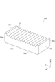
- FIG. 1 is a perspective view of an optical connector according to an embodiment.
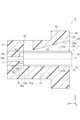
- FIG. 2 is a cross-sectional view of the optical connector of FIG.
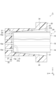
- FIG. 3 is another cross-sectional view of the optical connector of FIG.
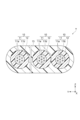
- FIG. 4 is a cross-sectional view of the ribbon fiber taken along line IV-IV in FIG.
- FIG. 5 is a cross-sectional view of an optical connector ferrule included in the optical connector of FIG.
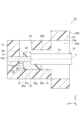
- FIG. 6 is another cross-sectional view of the optical connector ferrule of FIG.
- FIG. 7 is a side view of the ribbon fiber provided in the optical connector of FIG.
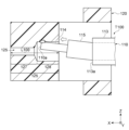
- FIG. 8 is a diagram showing how the ribbon fiber of FIG. 7 is mounted in an optical connector ferrule.
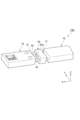
- FIG. 9 is a perspective view of an optical coupling structure including the optical connector of FIG. FIG.
- the clearance between the fiber insertion hole and the splice end of the optical fiber is small, so that it is desirable to insert the splice end of the optical fiber into the fiber insertion hole as straight as possible in order to avoid the contact of the splice end of the optical fiber with the fiber insertion hole.
- the splice end position of the optical fiber is likely to deviate from the ideal position depending on the length of the optical fiber from the outer jacket. Therefore, the splice end of the optical fiber may be inserted into the fiber insertion hole in a state where the attitude of the splice end is greatly tilted.
- the splice end may come into strong contact with the fiber insertion hole, causing the optical fiber to twist and rotate, resulting in a change in the installation state.
- Such a change in the installation state of the optical fiber may cause deterioration of the optical characteristics, such as an increase in connection loss.
- the holding member may be a resin layer that surrounds only the coating of the multiple optical fibers.
- the holding member by holding the relatively strong coating of the optical fiber with the holding member, it is possible to reduce the occurrence of damage to the optical fiber due to stress concentration at the boundary between the holding member and the optical fiber.
- the holding member may be a resin layer that surrounds only the tips of the optical fibers.
- the clearance between the tips and the holding member can be reduced, so that the positional deviation of the tips of the optical fibers can be further reduced. This makes it possible to more reliably reduce the occurrence of fluctuations in the installation state of the optical fibers.
- the holding member may penetrate in a first direction and be arranged in a second direction, and may have a plurality of through holes into which a plurality of optical fibers are respectively inserted.
- the tip of the optical fiber can be inserted into the holding portion of each insertion hole while the orientation of the optical fiber is adjusted by the through holes. This reduces the occurrence of fluctuations in the installation state, such as twisting and rotation of the optical fiber, due to friction between the insertion hole etc. and the tip.
- FIG 2 is a cross-sectional view showing the XZ cross section of the optical connector 1.
- Figure 3 is a cross-sectional view showing the XY cross section of the optical connector 1.
- Figure 4 is a cross-sectional view of the ribbon fiber T taken along line IV-IV in Figure 2.
- each optical fiber 10 has a tip portion 14 and a coating portion 15.
- the tip portion 14 is the portion of the glass portion 11 of the optical fiber 10 that protrudes forward from the coating end 15a of the coating portion 15.
- the tip portion 14 is the glass portion 11 from the coating end 15a to the tip 10a.
- the coating end 15a is the front edge of the coating portion 15, and is located at the boundary between the coating portion 15 and the tip portion 14.
- the glass portion 11 is exposed and not covered by the coating portion 15.
- the tip 14 is formed by removing a predetermined length of the resin coating 12 from the tip 10a. Therefore, the tip 14 can also be said to be a coating-removed portion where the resin coating 12 has been removed.
- the outer diameter of the tip 14 i.e., the diameter of the glass portion 11
- the coating portion 15 is the portion where the glass portion 11 is covered by the resin coating 12. In other words, the coating portion 15 is the portion of the optical fiber 10 behind the coated end 15a.
- the outer diameter of the coating portion 15 may be, for example, 50 ⁇ m or more and 500 ⁇ m or less.
- the upper surface 32 faces the lower surface 31 in the Z direction and is spaced upward from the lower surface 31.
- the upper surface 32 is, for example, a flat surface that is inclined relative to the lower surface 31 along the XY plane.
- the upper surface 32 is inclined relative to the lower surface 31 so that the Z-direction distance between the upper surface 32 and the lower surface 31 becomes narrower as the upper surface 32 approaches the inner wall surface 26 from the rear end surface 22 in the X direction.
- the minimum value of the Z-direction distance between the upper surface 32 and the lower surface 31 is set to be larger than the Z-direction width of the tape resin 13.
- a window 35 for injecting adhesive is connected to the upper surface 32. The window 35 penetrates in the Z direction from the upper surface 32 to the outer surface of the ferrule 20 above.
- side 33 and side 34 face each other in the Y direction and are arranged with a gap in between in the Y direction.
- Side 33 and side 34 are, for example, flat surfaces inclined from the XZ plane perpendicular to the Y direction.
- Side 33 and side 34 are inclined with respect to the XZ plane such that the gap in the Y direction between side 33 and side 34 becomes narrower as they approach inner wall surface 26 from rear end surface 22 in the X direction.
- the minimum gap in the Y direction between side 33 and side 34 is set to be larger than the width of tape resin 13 in the Y direction.
- the lower surface 31, the upper surface 32, the side surface 33, and the side surface 34 are configured as a positioning mechanism for guiding the multiple optical fibers 10 to the multiple insertion holes 25.
- the lower surface 31 is a flat surface parallel to the XY plane, so that the Z-direction positions of the multiple optical fibers 10 relative to the multiple insertion holes 25 are defined.
- the arrangement direction of the multiple optical fibers 10 is restricted to a state along the arrangement direction of the multiple insertion holes 25 (i.e., the Y direction) (see Figures 2 and 3).
- the upper surface 32 is inclined so that the distance between the upper surface 32 and the lower surface 31 gradually narrows, so that the Z-direction positions of the multiple optical fibers 10 held in the tape resin 13 are determined with greater precision as the tape resin 13 advances in the introduction hole 24.
- the side surfaces 33 and 34 are inclined so that the distance between the side surfaces 33 and 34 gradually narrows, so that the Y-direction positions of the multiple optical fibers 10 held in the tape resin 13 are determined with greater precision as the tape resin 13 advances in the introduction hole 24.
- the positions of the multiple optical fibers 10 relative to the multiple insertion holes 25 in the YZ plane are precisely determined by the bottom surface 31, the top surface 32, the side surface 33, and the side surface 34.
- Each insertion hole 25 has a holding portion 27 that holds the tip 14 of the optical fiber 10, and a tapered portion 28 (introduction portion) for introducing the tip 14 of the optical fiber 10 into the holding portion 27.
- the holding portion 27 is a circular small-diameter hole extending in the X direction from the front end face 21.
- the holding portion 27 has a constant inner diameter at each position along the X direction.
- the inner diameter of the holding portion 27 is large enough to hold the tip 14.
- the inner diameter of the holding portion 27 is set so that the clearance between the holding portion 27 and the tip 14 in the YZ plane is sufficiently small.
- the holding portion 27 opens at the front end face 21.
- the tip 10a of the optical fiber 10 inserted into the holding portion 27 is exposed from the opening of the front end face 21 (see Figures 2 and 3).
- the tapered portion 28 is disposed between the holding portion 27 and the inner wall surface 26.
- the tapered portion 28 extends in the X direction from the holding portion 27 to the inner wall surface 26.
- the tapered portion 28 connects the holding portion 27 and the inner wall surface 26 in the X direction.
- the tapered portion 28 has an inner diameter larger than the inner diameter of the holding portion 27.
- the inner diameter of the tapered portion 28 becomes smaller in the X direction from the inner wall surface 26 to the holding portion 27. In other words, the tapered portion 28 gradually reduces in diameter as it approaches the holding portion 27.
- the tapered portion 28 opens at the inner wall surface 26.
- the optical fiber 10 is inserted from the opening of the inner wall surface 26. When the optical fiber 10 is inserted into the insertion hole 25, the tip 14 of the optical fiber 10 is guided by the tapered portion 28 to the holding portion 27 and inserted into the holding portion 27.
- the length L of the insertion hole 25 in the X direction is set to 1.5 mm or less.
- the length L of the insertion hole 25 corresponds to the distance in the X direction from the front end surface 21 where the front end of the insertion hole 25 is located to the inner wall surface 26 where the rear end of the insertion hole 25 is located.
- the length L of the insertion hole 25 is the total length of the length L1 of the holding portion 27 in the X direction and the length L2 of the tapered portion 28 in the X direction.
- the length L1 of the holding portion 27 is set to be longer than the length L2 of the tapered portion 28, for example.
- the optical fiber 10 protruding from the end face 13a can also be shortened to a maximum of 1.5 mm. If the length L of the insertion hole 25 is shortened, the length L10 of the optical fiber 10 can be shortened, as described later. Therefore, it is effective in reducing the positional deviation of the tip 10a of the optical fiber 10.
- the length L of the insertion hole 25 can be measured by cutting the ferrule 20 in the X direction at a cross section including the insertion hole 25 and observing the cross section under a microscope.
- FIG. 13 is a cross-sectional view of the optical connector 1A according to the first modification.
- the tape resin 13 surrounds only the tip 14 of the optical fiber 10 among the tip 14 and the coating 15 in a bundle.
- a part of the tip 14 protrudes from the end face 13a of the tape resin 13, and the remaining part of the tip 14 is covered by the tape resin 13.
- the coating 15 is located, for example, behind the tape resin 13. In this way, even if only the tip 14 of the optical fiber 10 is held by the tape resin 13, the same effect as the above-mentioned embodiment can be obtained.
- FIG. 17 is a cross-sectional view of an optical connector 1D according to the fourth modification.
- FIG. 18 is another cross-sectional view of the optical connector 1D.
- FIG. 19 is a cross-sectional view of the optical connector 1D along the line XIX-XIX in FIG. 17.
- the introduction hole 24C includes a convex portion 45 on the lower surface 31.
- the upper surface 32C, the side surface 33B, and the side surface 34B of the introduction hole 24C extend in the X direction without inclining.
- the upper surface 32C extends, for example, parallel to the lower surface 31.
- the Z-direction interval between the upper surface 32B and the lower surface 31 is constant at each position along the X direction.
- the side surface 33B and the side surface 34B extend, for example, parallel to each other.
- the Y-direction interval between the side surface 33B and the side surface 34B is constant at each position along the X direction.
- FIG. 20 is a cross-sectional view of the ferrule 20C.
- FIG. 21 is another cross-sectional view of the ferrule 20C.
- the convex portion 45 protrudes upward from the lower surface 31 toward the upper surface 32C.
- the height of the top surface of the convex portion 45 from the lower surface 31 is lower than the height of the top surface of the protrusion 37 from the lower surface 31.
- the convex portion 45 extends linearly in the X direction from the abutting surface 37a of the protrusion 37 to the rear end surface 22 at the center of the Y direction of the lower surface 31.
- the width of the convex portion 45 in the Y direction is smaller than the width of the protrusion 37 in the Y direction, for example.
- the recess 46 of the tape resin 13A fits into the protrusion 45 of the introduction hole 24C, thereby determining the position of the tape resin 13A in the YZ plane in the introduction hole 24C, i.e., the position of the optical fiber 10 in the YZ plane relative to the insertion hole 25.
- the tape resin 13A advances until the end face 13a of the tape resin 13A abuts against the abutment surface 37a, thereby positioning the optical fiber 10 relative to the insertion hole 25. Therefore, the protrusion 45 and the recess 46 can function as a positioning mechanism for determining the position of the optical fiber 10 in the YZ plane.
- the optical fiber holding member 30 includes, for example, a front end face 30a, a rear end face 30b, an upper face 30c, a lower face 30d, a side face 30e, and a side face 30f.
- the front end face 30a and the rear end face 30b are, for example, planes along the YZ plane, and are arranged side by side along the X direction.
- the upper face 30c and the lower face 30d are, for example, planes along the XY plane, and are arranged side by side along the Z direction.
- the side surface 30e and the side surface 30f are, for example, flat surfaces along the XZ plane, and are arranged side by side along the Y direction.
Landscapes
- Physics & Mathematics (AREA)
- General Physics & Mathematics (AREA)
- Optics & Photonics (AREA)
- Mechanical Coupling Of Light Guides (AREA)
Priority Applications (3)
| Application Number | Priority Date | Filing Date | Title |
|---|---|---|---|
| JP2024568703A JPWO2024147241A1 (https=) | 2023-01-04 | 2023-11-27 | |
| EP23914729.1A EP4647820A4 (en) | 2023-01-04 | 2023-11-27 | OPTICAL CONNECTOR FERRULE, OPTICAL CONNECTOR AND OPTICAL COUPLING STRUCTURE |
| CN202380082147.7A CN120283185A (zh) | 2023-01-04 | 2023-11-27 | 光连接器插芯、光连接器以及光耦合结构 |
Applications Claiming Priority (2)
| Application Number | Priority Date | Filing Date | Title |
|---|---|---|---|
| JP2023-000155 | 2023-01-04 | ||
| JP2023000155 | 2023-01-04 |
Publications (1)
| Publication Number | Publication Date |
|---|---|
| WO2024147241A1 true WO2024147241A1 (ja) | 2024-07-11 |
Family
ID=91803838
Family Applications (1)
| Application Number | Title | Priority Date | Filing Date |
|---|---|---|---|
| PCT/JP2023/042329 Ceased WO2024147241A1 (ja) | 2023-01-04 | 2023-11-27 | 光コネクタフェルール、光コネクタ、及び光結合構造 |
Country Status (4)
| Country | Link |
|---|---|
| EP (1) | EP4647820A4 (https=) |
| JP (1) | JPWO2024147241A1 (https=) |
| CN (1) | CN120283185A (https=) |
| WO (1) | WO2024147241A1 (https=) |
Citations (8)
| Publication number | Priority date | Publication date | Assignee | Title |
|---|---|---|---|---|
| US6409394B1 (en) * | 2000-03-21 | 2002-06-25 | Sumitomo Electric Industries, Ltd. | Optical connector |
| JP2002236239A (ja) * | 2001-02-08 | 2002-08-23 | Toshiba Corp | 光ファイバ、光モジュール、光ファイバ装置 |
| JP2002333549A (ja) | 2001-05-08 | 2002-11-22 | Furukawa Electric Co Ltd:The | 光コネクタ用フェルール |
| JP2015527619A (ja) * | 2012-09-12 | 2015-09-17 | スリーエム イノベイティブ プロパティズ カンパニー | 遠隔グリップ多心コネクタ |
| WO2018055930A1 (ja) * | 2016-09-23 | 2018-03-29 | 住友電気工業株式会社 | 光コネクタフェルール及び光コネクタ |
| WO2018135368A1 (ja) * | 2017-01-17 | 2018-07-26 | 住友電気工業株式会社 | 光ファイバ保持部品、光コネクタ、及び光結合構造 |
| JP2020160350A (ja) * | 2019-03-27 | 2020-10-01 | 住友電気工業株式会社 | 光コネクタフェルール及び光コネクタ |
| JP2023000155A (ja) | 2021-06-17 | 2023-01-04 | 高光産業株式会社 | 車両 |
Family Cites Families (4)
| Publication number | Priority date | Publication date | Assignee | Title |
|---|---|---|---|---|
| JPS61209404A (ja) * | 1985-03-13 | 1986-09-17 | Furukawa Electric Co Ltd:The | 多心光フアイバコネクタの製造方法 |
| US6634800B2 (en) * | 2000-04-27 | 2003-10-21 | Furukawa Electric Co., Ltd. | Ferrule for optical connector |
| WO2016007491A1 (en) * | 2014-07-07 | 2016-01-14 | Adc Telecommunications, Inc. | Optical ferrule for multi-fiber cable and hardened multi-fiber optic connector therefore |
| WO2018089286A1 (en) * | 2016-11-08 | 2018-05-17 | Molex, Llc | Multi-fiber ferrule with lens elements |
-
2023
- 2023-11-27 WO PCT/JP2023/042329 patent/WO2024147241A1/ja not_active Ceased
- 2023-11-27 CN CN202380082147.7A patent/CN120283185A/zh active Pending
- 2023-11-27 EP EP23914729.1A patent/EP4647820A4/en active Pending
- 2023-11-27 JP JP2024568703A patent/JPWO2024147241A1/ja active Pending
Patent Citations (8)
| Publication number | Priority date | Publication date | Assignee | Title |
|---|---|---|---|---|
| US6409394B1 (en) * | 2000-03-21 | 2002-06-25 | Sumitomo Electric Industries, Ltd. | Optical connector |
| JP2002236239A (ja) * | 2001-02-08 | 2002-08-23 | Toshiba Corp | 光ファイバ、光モジュール、光ファイバ装置 |
| JP2002333549A (ja) | 2001-05-08 | 2002-11-22 | Furukawa Electric Co Ltd:The | 光コネクタ用フェルール |
| JP2015527619A (ja) * | 2012-09-12 | 2015-09-17 | スリーエム イノベイティブ プロパティズ カンパニー | 遠隔グリップ多心コネクタ |
| WO2018055930A1 (ja) * | 2016-09-23 | 2018-03-29 | 住友電気工業株式会社 | 光コネクタフェルール及び光コネクタ |
| WO2018135368A1 (ja) * | 2017-01-17 | 2018-07-26 | 住友電気工業株式会社 | 光ファイバ保持部品、光コネクタ、及び光結合構造 |
| JP2020160350A (ja) * | 2019-03-27 | 2020-10-01 | 住友電気工業株式会社 | 光コネクタフェルール及び光コネクタ |
| JP2023000155A (ja) | 2021-06-17 | 2023-01-04 | 高光産業株式会社 | 車両 |
Non-Patent Citations (1)
| Title |
|---|
| See also references of EP4647820A1 |
Also Published As
| Publication number | Publication date |
|---|---|
| JPWO2024147241A1 (https=) | 2024-07-11 |
| CN120283185A (zh) | 2025-07-08 |
| EP4647820A1 (en) | 2025-11-12 |
| EP4647820A4 (en) | 2026-04-22 |
Similar Documents
| Publication | Publication Date | Title |
|---|---|---|
| JP7040464B2 (ja) | 光ファイバ保持部品、光コネクタ、及び光結合構造 | |
| US11054586B2 (en) | Optical connector and optical connection structure | |
| US6331081B1 (en) | Optical transmission member and manufacturing method therefor | |
| JP7718521B2 (ja) | 光コネクタの製造方法 | |
| WO2023199632A1 (ja) | 光ファイバ保持部品、光ファイバ結合構造体、光コネクタ、及び光結合構造 | |
| JP7388368B2 (ja) | フェルール及び光コネクタ | |
| WO2024147241A1 (ja) | 光コネクタフェルール、光コネクタ、及び光結合構造 | |
| JP7786395B2 (ja) | 光コネクタ及び光接続構造 | |
| WO2024142472A1 (ja) | 光ファイバ保持部品およびフェルールアセンブリ | |
| JP7435692B2 (ja) | 光コネクタの接続方法 | |
| TWI890959B (zh) | 多芯光套管、多芯光連接器及多芯光套管的製造方法 | |
| US20260016643A1 (en) | Optical connector, ferrule, and optical coupling structure | |
| WO2025239152A1 (ja) | 光コネクタ | |
| CN121399515A (zh) | 保持构件、光连接器以及光连接组件 | |
| CN118056148A (zh) | 光连接器 | |
| WO2024252931A1 (ja) | 光ファイバ保持部品、光ファイバアセンブリ、光コネクタ、および光結合デバイス | |
| US20250138252A1 (en) | Optical connector ferrule and optical connector | |
| WO2025075063A1 (ja) | 光コネクタ、光接続アセンブリ、光導波路部材、および光コネクタの製造方法 | |
| JPWO2024029270A5 (https=) | ||
| WO2025075062A1 (ja) | 光コネクタ、光接続アセンブリ、および光コネクタの製造方法 | |
| WO2024176680A1 (ja) | フェルール、光コネクタ、及び光コネクタの製造方法 | |
| JP2002148486A (ja) | 多心光コネクタ | |
| JPH1138269A (ja) | 光コネクタおよびその製造方法 |
Legal Events
| Date | Code | Title | Description |
|---|---|---|---|
| 121 | Ep: the epo has been informed by wipo that ep was designated in this application |
Ref document number: 23914729 Country of ref document: EP Kind code of ref document: A1 |
|
| WWE | Wipo information: entry into national phase |
Ref document number: 2024568703 Country of ref document: JP |
|
| WWE | Wipo information: entry into national phase |
Ref document number: 202380082147.7 Country of ref document: CN |
|
| WWP | Wipo information: published in national office |
Ref document number: 202380082147.7 Country of ref document: CN |
|
| WWE | Wipo information: entry into national phase |
Ref document number: 2023914729 Country of ref document: EP |
|
| NENP | Non-entry into the national phase |
Ref country code: DE |
|
| ENP | Entry into the national phase |
Ref document number: 2023914729 Country of ref document: EP Effective date: 20250804 |
|
| WWP | Wipo information: published in national office |
Ref document number: 2023914729 Country of ref document: EP |