WO2024143337A1 - 構造部材及びその製造方法 - Google Patents
構造部材及びその製造方法 Download PDFInfo
- Publication number
- WO2024143337A1 WO2024143337A1 PCT/JP2023/046588 JP2023046588W WO2024143337A1 WO 2024143337 A1 WO2024143337 A1 WO 2024143337A1 JP 2023046588 W JP2023046588 W JP 2023046588W WO 2024143337 A1 WO2024143337 A1 WO 2024143337A1
- Authority
- WO
- WIPO (PCT)
- Prior art keywords
- lower die
- structural member
- top plate
- die
- corner portion
- Prior art date
- Legal status (The legal status is an assumption and is not a legal conclusion. Google has not performed a legal analysis and makes no representation as to the accuracy of the status listed.)
- Ceased
Links
Images










Classifications
-
- B—PERFORMING OPERATIONS; TRANSPORTING
- B21—MECHANICAL METAL-WORKING WITHOUT ESSENTIALLY REMOVING MATERIAL; PUNCHING METAL
- B21D—WORKING OR PROCESSING OF SHEET METAL OR METAL TUBES, RODS OR PROFILES WITHOUT ESSENTIALLY REMOVING MATERIAL; PUNCHING METAL
- B21D22/00—Shaping without cutting, by stamping, spinning, or deep-drawing
- B21D22/20—Deep-drawing
- B21D22/22—Deep-drawing with devices for holding the edge of the blanks
-
- B—PERFORMING OPERATIONS; TRANSPORTING
- B21—MECHANICAL METAL-WORKING WITHOUT ESSENTIALLY REMOVING MATERIAL; PUNCHING METAL
- B21D—WORKING OR PROCESSING OF SHEET METAL OR METAL TUBES, RODS OR PROFILES WITHOUT ESSENTIALLY REMOVING MATERIAL; PUNCHING METAL
- B21D22/00—Shaping without cutting, by stamping, spinning, or deep-drawing
- B21D22/20—Deep-drawing
-
- B—PERFORMING OPERATIONS; TRANSPORTING
- B21—MECHANICAL METAL-WORKING WITHOUT ESSENTIALLY REMOVING MATERIAL; PUNCHING METAL
- B21D—WORKING OR PROCESSING OF SHEET METAL OR METAL TUBES, RODS OR PROFILES WITHOUT ESSENTIALLY REMOVING MATERIAL; PUNCHING METAL
- B21D24/00—Special deep-drawing arrangements in, or in connection with, presses
- B21D24/005—Multi-stage presses
-
- B—PERFORMING OPERATIONS; TRANSPORTING
- B21—MECHANICAL METAL-WORKING WITHOUT ESSENTIALLY REMOVING MATERIAL; PUNCHING METAL
- B21D—WORKING OR PROCESSING OF SHEET METAL OR METAL TUBES, RODS OR PROFILES WITHOUT ESSENTIALLY REMOVING MATERIAL; PUNCHING METAL
- B21D53/00—Making other particular articles
- B21D53/88—Making other particular articles other parts for vehicles, e.g. cowlings, mudguards
Definitions
- the ridge portions 112 and 113 are provided on both sides of the top plate 111.
- the ridge portion 112 extends along the edge of the top plate 111.
- the ridge portion 112 in a plan view of the structural member 10, that is, when the structural member 10 is viewed from the top plate 111 side, the ridge portion 112 includes a curved portion.
- the ridge portion 113 extends along the edge of the top plate 111 on the opposite side to the ridge portion 112.
- the distance between the ridge portions 112 and 113 in a plan view of the structural member 10, that is, the width of the top plate 111 is smaller on one side of the longitudinal direction of the member body 11 and larger on the other side.
- the ridge portions 112 and 113 can each have a substantially arc shape when viewed in a cross section (transverse cross section) perpendicular to their extension direction.
- the flange portion 116 is connected to one vertical wall 114 on the opposite side of the top plate 111.
- the flange portion 117 is connected to the other vertical wall 115 on the opposite side of the top plate 111.
- the flange portions 116, 117 protrude from the vertical walls 114, 115, respectively, toward the outside of the structural member 10.
- the flange portions 116, 117 extend along the vertical walls 114, 115, respectively.
- the vertical wall 123 is connected to the top plate 121 via the ridge portion 122.
- the vertical wall 123 is connected to one of the vertical walls 114 of the member body 11 via the corner portion 13.
- the vertical wall 123 of the continuous flange 12 is bent relative to the vertical wall 114 of the member body 11.
- the flange portion 124 is connected to the vertical wall 123 on the opposite side of the top plate 121.
- the flange portion 124 protrudes from the vertical wall 123 toward the outside of the structural member 10.
- the flange portion 124 is continuous with one of the flange portions 116 of the member body 11.
- the preparation step is a step of preparing a material made of a metal plate.
- the material may be, for example, a steel plate having a tensile strength of 590 MPa or more, preferably 980 MPa or more, more preferably 1180 MPa or more.
- the material may be, for example, a blank having a shape obtained by developing the structural member 10 (FIGS. 1 to 3). Such a blank may be formed by punching a metal strip (coil) using a mold having a desired shape. Alternatively, the blank may be formed by hollowing out a coil using a laser.
- the material may be, for example, a preformed body formed by preforming a blank.
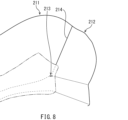
- the shoulder portion 211b extends along the edge of the top surface 211a.
- the shoulder portion 211b is a surface that is primarily used to form the ridge portion 112 (FIGS. 1 to 3) of the member body 11. Therefore, the shoulder portion 211b has a shape that corresponds to the ridge portion 112.
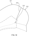
- the lower die 21 further includes a corner portion 213.
- the corner portion 213 has a concave shape on the inside of the lower die 21 when viewed from the pressing direction.
- the corner portion 213 is disposed between the shoulder portion 211b and the side surface 211c of the first lower die 211 and the shoulder portion 212b and the side surface 212c of the second lower die 212.
- the shoulder portion 211b and the side surface 211c of the first lower die 211 are adjacent to the corner portion 213.
- the shoulder portion 212b and the side surface 212c of the second lower die 212 are adjacent to the corner portion 213 on the opposite side of the shoulder portion 211b and the side surface 211c of the first lower die 211.
- the shoulder portion 212b and the side surface 212c of the second lower die 212 are disposed so as to bend with respect to the shoulder portion 211b and the side surface 211c of the first lower die 211.
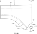
- Figure 4B is a view of the lower die 21 viewed from the top surfaces 211a, 212a along the press direction.
- the parting line 214 between the first lower die 211 and the second lower die 212 is positioned in the range from the end (R end) of the corner portion 213 on the second lower die 212 side to the end (R end) on the first lower die 211 side.
- the lower die 21 is divided into a first lower die 211 and a second lower die 212 at the position of a parting line 214.
- the second lower die 212 is set back from the first lower die 211. More specifically, the first lower die 211 and the second lower die 212 are positioned so that the shoulder 212b and side 212c of the second lower die 212 are set back from the position of the shoulder 211b and side 211c of the first lower die 211 when viewed from the pressing direction.
- the upper die 22 and the pad 23 are arranged to face the lower die 21 in the pressing direction.
- the upper die 22 is attached to, for example, a slide (not shown) that can be raised and lowered in a press machine.
- the pad 23 is connected to the slide, for example, via an expandable and contractible elastic member (not shown).
- the pad 23 mainly faces the top surface 211a of the first lower die 211.
- the molding surface 221 of the upper die 22 mainly faces the top surface 212a of the second lower die 212.
- the molding surface 221 of the upper die 22 has a shape corresponding to the shoulder 211b, side surface 211c, and flange surface 211d of the first lower die 211, the top surface 212a, shoulder 212b, and side surface 212c of the second lower die 212, and the corner portion 213.
- the parting line 24 between the upper mold 22 and the pad 23 is preferably located at the position of the corner portion 213 (FIG. 4B) or near the corner portion 213.
- the parting line 24 between the upper mold 22 and the pad 23 may be located at the same position as the parting line 214 between the first lower mold 211 and the second lower mold 212 (FIG. 4B), or may be located shifted from the parting line 214 to the first lower mold 211 side or the second lower mold 212 side.
- the mold 20 thus configured is used to perform cold pressing on the material to form it.
- the molding process includes a first process and a second process.
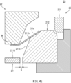
- FIG. 4D is a schematic diagram showing the IVD-IVD cross section of FIG. 4C.
- the second lower die 212 is positioned laterally spaced apart from the flange surface 211d of the first lower die 211.
- the second lower die 212 is positioned with a gap G between it and the first lower die 211.
- the second lower die 212 is attached to a press machine (not shown) via a cam mechanism 25.
- the cam mechanism 25 includes a cam driver 251 for moving the second lower die 212.
- the upper die 22 and pad 23 are brought relatively close to the lower die 21 in the pressing direction, and the material M arranged between the upper die 22 and pad 23 and the lower die 21 is sandwiched and pressed by the pad 23 and the first lower die 211.
- the pad 23 presses the material M prior to the upper die 22.
- the pad 23 presses the material M together with the top surface 211a of the first lower die 211, but does not substantially press the material M between the pad 23 and the top surface 212a of the second lower die 212.
- the portion of the material M that is mainly located on the top surface 211a of the first lower die 211 is pressed by the pad 23, but the portion of the material M that is located on the top surface 212a of the second lower die 212 is not pressed at all or almost not by the pad 23.
- the upper die 22 is brought even closer to the lower die 21 in the pressing direction to sandwich the material M between the upper die 22 and the first lower die 211, and the second lower die 212 is moved so that the side 212c of the second lower die 212 is aligned with the side 211c of the first lower die 211 when viewed from the pressing direction, to sandwich the material M between the upper die 22 and the second lower die 212.
- the state in which the side 212c of the second lower die 212 is aligned with the side 211c of the first lower die 211 refers to a state in which the difference in height (step) between adjacent side faces 211c, 212c is, for example, 0.5 mm or less.
- the upper die 22 is brought closer relative to the first lower die 211 and the second lower die 212 in the pressing direction.
- the material M is pressed down by the upper die 22.
- the material M is not sandwiched between the upper die 22 and the pad 23 and the second lower die 212. Therefore, at the position of the second lower die 212, the material M is pressed down by the upper die 22 and pulled towards the flange surface 211d, promoting the flow of material from the top surface 212a side to the side surface 212c side.
- the cam driver 251 of the cam mechanism 25 operates at the end of the second step.
- the cam driver 251 moves the second lower die 212 in a direction perpendicular to the press direction as it descends in the press direction.
- the second lower die 212 starts moving by the cam mechanism 25, for example, just before the upper die 22 reaches the bottom dead point.
- FIG. 4G for example, the second lower die 212 reaches the position of the first lower die 211 and stops at the same time as the upper die 22 reaches the bottom dead point, and the second lower die 212 and the upper die 22 clamp the material M.
- the gap between the flange surface 211d of the first lower die 211 and the second lower die 212 substantially disappears.
- the travel distance (cam stroke) of the second lower die 212 in the second molding step is preferably 9.0 times or less the thickness of the material M.
- the travel distance of the second lower die 212 may be, for example, 2.0 times or more the thickness of the material M.
- the thickness of the material M is, for example, 0.8 mm or more and 4.0 mm or less, and preferably 1.0 mm or more and 3.0 mm or less.
- the travel distance of the second lower die 212 is equal to the gap G ( Figure 4D) between the second lower die 212 and the first lower die 211 at the start of molding.
- the molding process described in this embodiment may be included in the manufacturing process until the structural member 10 attains the shape of the final product. If the manufacturing process includes multiple molding processes, the molding process described in this embodiment may be the first molding process, an intermediate molding process, or the final molding process.
- the first lower die 211 and the second lower die 212 are arranged so that the position of the side surface 212c of the second lower die 212 is set back from the position of the side surface 211c of the first lower die 211 when viewed from the pressing direction at the start of the molding process. Therefore, when the upper die 22 and the pad 23 are brought relatively close to the first lower die 211 and the second lower die 212, the material M is not constrained at the position of the second lower die 212. The second lower die 212 starts to clamp the material M together with the upper die 22 from the later stage of the molding process to form the continuous flange 12.
- the part of the corner portion 213 that becomes part of the second lower die 212 does not constrain the material M until the later stages of the molding process, so that the bending of the continuous flange 12 during the molding process is gentler and the distortion of the continuous flange 12 is reduced. This makes it even less likely that cracks will occur in the continuous flange 12.
- the continuous flange 12 is not restrained until the later stage of the forming process as described above, and the strain of the continuous flange 12 can be dispersed, so that the occurrence of cracks in the continuous flange 12 can be suppressed even when the radius of curvature of the corner portion 13 is small.
- a Vickers hardness test is performed in accordance with JIS Z 2244.
- the Vickers hardness is measured, for example, with a test force of 294.2 N (the value of HV30) and a test force holding time of 15 s.
- the Vickers hardness is measured at a position 1/4 of the plate thickness from the surface of the top plate 121 in the cross section of the test specimen.
- the structural member 10 or 10A may be divided after molding. This allows multiple structural members 10 or 10A including one or more continuous flanges 12 to be manufactured in a single molding process.
- the dividing position between the first lower die 211 and the second lower die 212 was "R start”
- the cracking was rated as acceptable
- the dividing position was "R center” and "R end”
- the cracking was rated as good in most cases, and the cracking of the continuous flange 12 was improved. Therefore, in order to more easily suppress the occurrence of cracks in the continuous flange 12, it can be said that it is preferable that the dividing line 214 between the first lower die 211 and the second lower die 212 is located in the middle in the extension direction of the corner portion 213, or closer to the first lower die 211 than the middle.
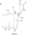
- Comparative Example 1 the Vickers hardness at the R start of the corner portion 13 (end E2 shown in Figure 5) was significantly smaller than the Vickers hardness at the edge E1 of the continuous flange. In Comparative Example 1, the difference in Vickers hardness between the edge E1 of the continuous flange and the R start E2 of the corner portion 13 was 49 Hv.
- the Vickers hardness at the R start E2 of the corner portion 13 is not significantly lower than the Vickers hardness at the edge E1 of the continuous flange.
- the difference in Vickers hardness between the edge E1 of the continuous flange and the R start E2 of the corner portion 13 is 9 Hv in Example 1, 13 Hv in Example 2, and 25 Hv in Example 8.
Landscapes
- Engineering & Computer Science (AREA)
- Mechanical Engineering (AREA)
- Shaping Metal By Deep-Drawing, Or The Like (AREA)
- Forging (AREA)
Priority Applications (3)
| Application Number | Priority Date | Filing Date | Title |
|---|---|---|---|
| JP2024521837A JP7525817B1 (ja) | 2022-12-26 | 2023-12-26 | 構造部材及びその製造方法 |
| EP23912116.3A EP4644014A1 (en) | 2022-12-26 | 2023-12-26 | Structural member and method for manufacturing same |
| CN202380088680.4A CN120418017A (zh) | 2022-12-26 | 2023-12-26 | 构造构件及其制造方法 |
Applications Claiming Priority (2)
| Application Number | Priority Date | Filing Date | Title |
|---|---|---|---|
| JP2022-208938 | 2022-12-26 | ||
| JP2022208938 | 2022-12-26 |
Publications (1)
| Publication Number | Publication Date |
|---|---|
| WO2024143337A1 true WO2024143337A1 (ja) | 2024-07-04 |
Family
ID=91718116
Family Applications (1)
| Application Number | Title | Priority Date | Filing Date |
|---|---|---|---|
| PCT/JP2023/046588 Ceased WO2024143337A1 (ja) | 2022-12-26 | 2023-12-26 | 構造部材及びその製造方法 |
Country Status (4)
| Country | Link |
|---|---|
| EP (1) | EP4644014A1 (https=) |
| JP (1) | JP7525817B1 (https=) |
| CN (1) | CN120418017A (https=) |
| WO (1) | WO2024143337A1 (https=) |
Families Citing this family (1)
| Publication number | Priority date | Publication date | Assignee | Title |
|---|---|---|---|---|
| JPWO2025142410A1 (https=) * | 2023-12-28 | 2025-07-03 |
Citations (7)
| Publication number | Priority date | Publication date | Assignee | Title |
|---|---|---|---|---|
| JP2010120061A (ja) * | 2008-11-20 | 2010-06-03 | Nissan Motor Co Ltd | プレス成形品、プレス成形品の製造方法および製造装置 |
| JP2011083807A (ja) | 2009-10-16 | 2011-04-28 | Daihatsu Motor Co Ltd | 断面ハット状部品の製造方法 |
| JP2016043402A (ja) * | 2014-08-26 | 2016-04-04 | Jfeスチール株式会社 | プレス成形用金型装置 |
| JP6690605B2 (ja) | 2017-07-06 | 2020-04-28 | Jfeスチール株式会社 | プレス成形方法 |
| WO2020100886A1 (ja) * | 2018-11-14 | 2020-05-22 | 日本製鉄株式会社 | 骨格部材 |
| JP2022072562A (ja) | 2020-10-30 | 2022-05-17 | 日本製鉄株式会社 | プレス成形方法、プレス成形用金型およびプレス成形用金型の設計方法 |
| JP7220800B2 (ja) * | 2019-10-04 | 2023-02-10 | 本田技研工業株式会社 | 車体構造 |
-
2023
- 2023-12-26 JP JP2024521837A patent/JP7525817B1/ja active Active
- 2023-12-26 CN CN202380088680.4A patent/CN120418017A/zh active Pending
- 2023-12-26 EP EP23912116.3A patent/EP4644014A1/en active Pending
- 2023-12-26 WO PCT/JP2023/046588 patent/WO2024143337A1/ja not_active Ceased
Patent Citations (7)
| Publication number | Priority date | Publication date | Assignee | Title |
|---|---|---|---|---|
| JP2010120061A (ja) * | 2008-11-20 | 2010-06-03 | Nissan Motor Co Ltd | プレス成形品、プレス成形品の製造方法および製造装置 |
| JP2011083807A (ja) | 2009-10-16 | 2011-04-28 | Daihatsu Motor Co Ltd | 断面ハット状部品の製造方法 |
| JP2016043402A (ja) * | 2014-08-26 | 2016-04-04 | Jfeスチール株式会社 | プレス成形用金型装置 |
| JP6690605B2 (ja) | 2017-07-06 | 2020-04-28 | Jfeスチール株式会社 | プレス成形方法 |
| WO2020100886A1 (ja) * | 2018-11-14 | 2020-05-22 | 日本製鉄株式会社 | 骨格部材 |
| JP7220800B2 (ja) * | 2019-10-04 | 2023-02-10 | 本田技研工業株式会社 | 車体構造 |
| JP2022072562A (ja) | 2020-10-30 | 2022-05-17 | 日本製鉄株式会社 | プレス成形方法、プレス成形用金型およびプレス成形用金型の設計方法 |
Non-Patent Citations (1)
| Title |
|---|
| See also references of EP4644014A1 |
Also Published As
| Publication number | Publication date |
|---|---|
| CN120418017A (zh) | 2025-08-01 |
| EP4644014A1 (en) | 2025-11-05 |
| JPWO2024143337A1 (https=) | 2024-07-04 |
| JP7525817B1 (ja) | 2024-07-31 |
Similar Documents
| Publication | Publication Date | Title |
|---|---|---|
| KR102407168B1 (ko) | 프레스 부품의 제조 방법 및 제조 장치 | |
| EP2896467B1 (en) | Method for producing curved article | |
| KR101701082B1 (ko) | 프레스 부품의 제조 방법 및 제조 장치 | |
| JP7311830B1 (ja) | 構造部材及びその製造方法 | |
| CN104903020B (zh) | 冲压成型品的制造方法 | |
| US9266162B2 (en) | Press-forming method of component with L shape | |
| CN105792957B (zh) | 压制成型装置、使用了该成型装置的压制成型品的制造方法以及压制成型品 | |
| KR101863469B1 (ko) | 강판 소재, 그 제조 방법 및 제조 장치, 및 그 강판 소재를 이용한 프레스 성형품의 제조 방법 | |
| KR101863482B1 (ko) | 프레스 성형품 및 이것을 구비한 자동차용 구조 부재, 및 그 프레스 성형품의 제조 방법 및 제조 장치 | |
| KR20180027547A (ko) | 프레스 부품의 제조 방법 및 제조 장치 | |
| KR20150113052A (ko) | 프레스 성형 부재의 제조 방법 및 프레스 성형 장치 | |
| JP2019025533A (ja) | プレス成形品の製造方法 | |
| KR102083108B1 (ko) | 프레스 성형품의 제조 방법 | |
| CN107921504B (zh) | 拉伸凸缘成形零件的制造方法 | |
| JP7525817B1 (ja) | 構造部材及びその製造方法 | |
| WO2015064175A1 (ja) | プレス成形方法 | |
| JP7273355B1 (ja) | 構造部材及びその製造方法 | |
| US11130163B2 (en) | Press molding method and press molding apparatus | |
| JP7494883B2 (ja) | プレス成形方法およびプレス成形品の製造方法 | |
| JP6176429B1 (ja) | プレス成形品の製造方法 | |
| JP7853355B2 (ja) | プレス成形品の製造方法 | |
| JP7239048B1 (ja) | プレス成形方法及びプレス成形品の製造方法 | |
| WO2025142410A1 (ja) | 構造部材の製造方法、構造部材、及び金型セット |
Legal Events
| Date | Code | Title | Description |
|---|---|---|---|
| WWE | Wipo information: entry into national phase |
Ref document number: 2024521837 Country of ref document: JP |
|
| 121 | Ep: the epo has been informed by wipo that ep was designated in this application |
Ref document number: 23912116 Country of ref document: EP Kind code of ref document: A1 |
|
| WWE | Wipo information: entry into national phase |
Ref document number: 202517060243 Country of ref document: IN Ref document number: 202380088680.4 Country of ref document: CN |
|
| WWP | Wipo information: published in national office |
Ref document number: 202517060243 Country of ref document: IN |
|
| WWE | Wipo information: entry into national phase |
Ref document number: 2023912116 Country of ref document: EP |
|
| NENP | Non-entry into the national phase |
Ref country code: DE |
|
| WWP | Wipo information: published in national office |
Ref document number: 202380088680.4 Country of ref document: CN |
|
| ENP | Entry into the national phase |
Ref document number: 2023912116 Country of ref document: EP Effective date: 20250728 |
|
| ENP | Entry into the national phase |
Ref document number: 2023912116 Country of ref document: EP Effective date: 20250728 |
|
| WWP | Wipo information: published in national office |
Ref document number: 2023912116 Country of ref document: EP |