WO2024143124A1 - 分光分析装置及び分光分析方法 - Google Patents
分光分析装置及び分光分析方法 Download PDFInfo
- Publication number
- WO2024143124A1 WO2024143124A1 PCT/JP2023/045769 JP2023045769W WO2024143124A1 WO 2024143124 A1 WO2024143124 A1 WO 2024143124A1 JP 2023045769 W JP2023045769 W JP 2023045769W WO 2024143124 A1 WO2024143124 A1 WO 2024143124A1
- Authority
- WO
- WIPO (PCT)
- Prior art keywords
- light
- region
- incident
- standard
- spectroscopic analysis
- Prior art date
- Legal status (The legal status is an assumption and is not a legal conclusion. Google has not performed a legal analysis and makes no representation as to the accuracy of the status listed.)
- Ceased
Links
Images





Classifications
-
- G—PHYSICS
- G01—MEASURING; TESTING
- G01J—MEASUREMENT OF INTENSITY, VELOCITY, SPECTRAL CONTENT, POLARISATION, PHASE OR PULSE CHARACTERISTICS OF INFRARED, VISIBLE OR ULTRAVIOLET LIGHT; COLORIMETRY; RADIATION PYROMETRY
- G01J3/00—Spectrometry; Spectrophotometry; Monochromators; Measuring colours
- G01J3/28—Investigating the spectrum
- G01J3/44—Raman spectrometry; Scattering spectrometry ; Fluorescence spectrometry
-
- G—PHYSICS
- G01—MEASURING; TESTING
- G01J—MEASUREMENT OF INTENSITY, VELOCITY, SPECTRAL CONTENT, POLARISATION, PHASE OR PULSE CHARACTERISTICS OF INFRARED, VISIBLE OR ULTRAVIOLET LIGHT; COLORIMETRY; RADIATION PYROMETRY
- G01J3/00—Spectrometry; Spectrophotometry; Monochromators; Measuring colours
- G01J3/02—Details
- G01J3/0294—Multi-channel spectroscopy
-
- G—PHYSICS
- G01—MEASURING; TESTING
- G01N—INVESTIGATING OR ANALYSING MATERIALS BY DETERMINING THEIR CHEMICAL OR PHYSICAL PROPERTIES
- G01N21/00—Investigating or analysing materials by the use of optical means, i.e. using sub-millimetre waves, infrared, visible or ultraviolet light
- G01N21/62—Systems in which the material investigated is excited whereby it emits light or causes a change in wavelength of the incident light
- G01N21/63—Systems in which the material investigated is excited whereby it emits light or causes a change in wavelength of the incident light optically excited
- G01N21/65—Raman scattering
Definitions
- the present invention relates to a spectroscopic analysis device and a spectroscopic analysis method that irradiates a substance with primary light and analyzes the secondary light generated from the substance.
- a substance is irradiated with primary light, the secondary light generated from the substance is measured, and the substance is analyzed based on the spectrum of the secondary light. For example, Raman spectroscopy or fluorescence spectroscopy is performed.
- a method using a spectroscope and an image sensor may be used.
- the image sensor may be, for example, a two-dimensional image sensor such as a CCD (charge-coupled device) image sensor or a CMOS (complementary metal-oxide-semiconductor) image sensor.
- the secondary light is dispersed by the spectroscope, travels in different directions according to wavelength (or wave number, the same applies below), and is received by wavelength at different positions on the image sensor.
- the light receiving positions are aligned in a straight line in the x-axis direction on the image sensor. Since there is a correlation between the light receiving position on the image sensor and the wavelength, the spectrum of the secondary light can be obtained from the detection results of the image sensor.
- Patent Document 1 discloses a technology for correcting the wavelength of light in Raman spectroscopic analysis.
- the present invention was made in consideration of these circumstances, and its purpose is to provide a spectroscopic analysis device and a spectroscopic analysis method that can improve the accuracy of spectroscopic analysis by more accurately correcting the detection results.
- a spectroscopic analysis device has a first region and a second region different from the first region, and is characterized in that it comprises an image sensor that detects light incident on the first region and the second region, a first optical system that irradiates a sample with primary light and causes secondary light generated from the sample to be incident on the first region, a second optical system that causes standard light to be incident on the second region, and an analysis unit that corrects the detection result of the secondary light incident on the first region based on the detection result of the standard light incident on the second region.
- the first optical system disperses the secondary light and directs the dispersed secondary light to the first region
- the second optical system disperses the standard light and directs the dispersed standard light to the second region
- the first region has a plurality of incident positions at which a plurality of lights having different wavelengths are incident, arranged in a straight line
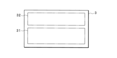
- the second region is disposed at a position on the imaging element that is shifted from the position of the first region in a direction that intersects with the direction in which the plurality of incident positions are arranged.
- a plurality of incident positions where a plurality of light beams with different wavelengths are incident are arranged in a straight line.
- the second region is disposed at a position shifted from the position of the first region in a direction intersecting the direction in which the plurality of incident positions are arranged. No matter what wavelength the secondary light has, the incident position of the secondary light is never included in the second region. Therefore, the secondary light incident on the image sensor can be easily distinguished from the standard light.
- the spectroscopic analysis device further includes a memory unit, the memory unit pre-stores the wavelength of the standard light, and the analysis unit identifies the wavelength of the standard light incident on the second region, and corrects the wavelength of the secondary light incident on the first region based on the deviation between the identified wavelength and the wavelength of the standard light pre-stored in the memory unit.
- the spectroscopic analysis device corrects the wavelength of the secondary light based on the shift in the wavelength of the standard light. By making the correction based on the detection result of the standard light, it is possible to eliminate the shift in the actual wavelength at the time the secondary light is detected. As a result, the wavelength of the secondary light is accurately corrected.
- the spectroscopic analysis device generates primary light and standard light from light emitted by a light source. Only a single light source is required.
- the first optical system and the second optical system share a spectrometer, the first optical system inputs the secondary light into the spectrometer, the second optical system inputs the standard light into a position in the spectrometer that is different from the position into which the secondary light is input, and the spectrometer splits the input light and inputs the split light into the image sensor.
- the spectroscopic analysis device uses the same spectrometer to disperse the secondary light and cause it to enter the image sensor, and to disperse the standard light and cause it to enter the image sensor.
- the spectroscopic analysis device can be made smaller.
- the secondary light includes Raman scattered light.
- the spectroscopic analyzer detects secondary light including Raman scattered light.
- the wavelength of the secondary light is corrected, thereby correcting the Raman shift.
- the spectroscopic analyzer can obtain an accurate Raman spectrum.
- a spectroscopic analysis method has a first region and a second region different from the first region, and uses an image sensor that detects light incident on the first region and the second region, causes secondary light generated from a sample irradiated with primary light to be incident on the first region, causes standard light to be incident on the second region, and corrects the detection result of the secondary light incident on the first region based on the detection result of the standard light incident on the second region.
- secondary light generated from a sample irradiated with primary light is incident on a first region of the image sensor and detected.
- Standard light is incident on a second region of the image sensor and detected.
- the detection result of the secondary light incident on the first region is corrected based on the detection result of the standard light incident on the second region.
- Secondary light and standard light are easily distinguished, and correction is easily performed. By correcting based on the detection result of the standard light, it is possible to eliminate any discrepancy in the actual detection result of the secondary light at the time the secondary light is detected.
- the present invention has the advantage that it is possible to accurately correct the detection results of secondary light, improving the accuracy of spectroscopic analysis.
- FIG. 4 is a schematic diagram showing a slit onto which secondary light and standard light are incident.
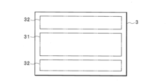
- 11 is a schematic diagram showing a light receiving surface of an image sensor according to a second embodiment.
- FIG. 11 is a block diagram showing a second configuration example of the spectroscopic analysis device according to the second embodiment.
- FIG. 11 is a block diagram showing an example of the configuration of a spectroscopic analysis device according to a third embodiment.
- Fig. 1 is a block diagram showing an example of the configuration of a spectroscopic analysis device 10 according to a first embodiment.
- the spectroscopic analysis device 10 executes a spectroscopic analysis method.
- the spectroscopic analysis device 10 is a Raman spectroscopic analysis device that irradiates a sample 6 with primary light, measures Raman scattered light contained in secondary light generated from the sample 6, and performs Raman spectroscopic analysis.
- light is indicated by arrows.
- the spectroscopic analysis device 10 includes a first optical system 1, a second optical system 2, and an image sensor 3.
- the first optical system 1 includes a light source 11 and a first spectroscope 12.
- the light source 11 emits monochromatic light.
- the light source 11 is a laser light source.
- the light source 11 generates primary light, which is irradiated onto the sample 6.
- secondary light is generated from the sample 6.
- the secondary light includes Raman scattered light.
- the secondary light is incident on the first spectroscope 12.
- the first spectroscope 12 disperses the incident secondary light and emits the dispersed secondary light.
- the first optical system 1 is configured to include optical components such as lenses, mirrors, and slits (not shown).
- the first optical system 1 is configured so that the primary light from the light source 11 is incident on the sample 6, the secondary light from the sample 6 is incident on the first spectroscope 12, and the secondary light dispersed by the first spectroscope 12 is incident on the image sensor 3.
- the secondary light split by the first spectrometer 12 is incident on the first region 31, and the standard light split by the second spectrometer 22 is incident on the second region 32.
- the secondary light dispersed by the first spectroscope 12 does not enter the second region 32, and the standard light dispersed by the second spectroscope 22 does not enter the first region 31.
- the first optical system 1 is configured so that the secondary light dispersed by the first spectroscope 12 enters the first region 31, and the second optical system 2 is configured so that the standard light dispersed by the second spectroscope 22 enters the second region 32.
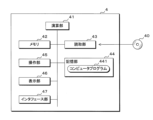
- the analysis unit 4 stores data representing the detection results from the image sensor 3 in the memory unit 44.
- the calculation unit 41 executes processing to analyze the Raman scattered light, such as generating a Raman spectrum, based on the detection results from the image sensor 3.
- the display unit 46 displays the processing results.
- the control unit 5 and analysis unit 4 may be integrated.
- FIG. 5 is a flowchart showing an example of the procedure of the process executed by the spectroscopic analysis device 10 to detect light and correct the wavelength of the light.
- steps are abbreviated as S.
- the calculation unit 41 of the analysis unit 4 executes the following process according to the computer program 441.
- the spectroscopic analysis device 10 causes the secondary light dispersed by the first optical system 1 to enter the image sensor 3, and causes the standard light dispersed by the second optical system 2 to enter the image sensor 3 (S1).
Landscapes
- Physics & Mathematics (AREA)
- Spectroscopy & Molecular Physics (AREA)
- General Physics & Mathematics (AREA)
- Investigating, Analyzing Materials By Fluorescence Or Luminescence (AREA)
Priority Applications (3)
| Application Number | Priority Date | Filing Date | Title |
|---|---|---|---|
| JP2024567691A JPWO2024143124A1 (https=) | 2022-12-28 | 2023-12-20 | |
| EP23911904.3A EP4636390A1 (en) | 2022-12-28 | 2023-12-20 | Spectroscopic analysis device and spectroscopic analysis method |
| CN202380088961.XA CN120418638A (zh) | 2022-12-28 | 2023-12-20 | 分光分析装置以及分光分析方法 |
Applications Claiming Priority (2)
| Application Number | Priority Date | Filing Date | Title |
|---|---|---|---|
| JP2022212367 | 2022-12-28 | ||
| JP2022-212367 | 2022-12-28 |
Publications (1)
| Publication Number | Publication Date |
|---|---|
| WO2024143124A1 true WO2024143124A1 (ja) | 2024-07-04 |
Family
ID=91717588
Family Applications (1)
| Application Number | Title | Priority Date | Filing Date |
|---|---|---|---|
| PCT/JP2023/045769 Ceased WO2024143124A1 (ja) | 2022-12-28 | 2023-12-20 | 分光分析装置及び分光分析方法 |
Country Status (4)
| Country | Link |
|---|---|
| EP (1) | EP4636390A1 (https=) |
| JP (1) | JPWO2024143124A1 (https=) |
| CN (1) | CN120418638A (https=) |
| WO (1) | WO2024143124A1 (https=) |
Cited By (1)
| Publication number | Priority date | Publication date | Assignee | Title |
|---|---|---|---|---|
| CN119715405A (zh) * | 2024-11-19 | 2025-03-28 | 中国科学院西安光学精密机械研究所 | 一种多狭缝高光谱图像数据的像移检测修正方法 |
Citations (7)
| Publication number | Priority date | Publication date | Assignee | Title |
|---|---|---|---|---|
| JPS51115066U (https=) * | 1975-03-14 | 1976-09-18 | ||
| JPH05332934A (ja) * | 1992-06-03 | 1993-12-17 | Jasco Corp | 分光装置 |
| JPH11142240A (ja) * | 1997-11-11 | 1999-05-28 | Jasco Corp | 分光装置 |
| JP2001242070A (ja) * | 2000-02-29 | 2001-09-07 | Mutsumi Corporation:Kk | 撮像装置 |
| JP2010145270A (ja) * | 2008-12-19 | 2010-07-01 | Yokogawa Electric Corp | 誘導ラマン分光分析装置 |
| WO2013047698A1 (ja) * | 2011-09-30 | 2013-04-04 | 学校法人東京理科大学 | 光干渉計、情報取得装置、及び情報取得方法 |
| JP6291817B2 (ja) | 2013-11-29 | 2018-03-14 | セイコーエプソン株式会社 | ラマン分光装置、電子機器、およびラマン分光測定方法 |
-
2023
- 2023-12-20 CN CN202380088961.XA patent/CN120418638A/zh active Pending
- 2023-12-20 EP EP23911904.3A patent/EP4636390A1/en active Pending
- 2023-12-20 JP JP2024567691A patent/JPWO2024143124A1/ja active Pending
- 2023-12-20 WO PCT/JP2023/045769 patent/WO2024143124A1/ja not_active Ceased
Patent Citations (7)
| Publication number | Priority date | Publication date | Assignee | Title |
|---|---|---|---|---|
| JPS51115066U (https=) * | 1975-03-14 | 1976-09-18 | ||
| JPH05332934A (ja) * | 1992-06-03 | 1993-12-17 | Jasco Corp | 分光装置 |
| JPH11142240A (ja) * | 1997-11-11 | 1999-05-28 | Jasco Corp | 分光装置 |
| JP2001242070A (ja) * | 2000-02-29 | 2001-09-07 | Mutsumi Corporation:Kk | 撮像装置 |
| JP2010145270A (ja) * | 2008-12-19 | 2010-07-01 | Yokogawa Electric Corp | 誘導ラマン分光分析装置 |
| WO2013047698A1 (ja) * | 2011-09-30 | 2013-04-04 | 学校法人東京理科大学 | 光干渉計、情報取得装置、及び情報取得方法 |
| JP6291817B2 (ja) | 2013-11-29 | 2018-03-14 | セイコーエプソン株式会社 | ラマン分光装置、電子機器、およびラマン分光測定方法 |
Non-Patent Citations (1)
| Title |
|---|
| See also references of EP4636390A1 |
Cited By (1)
| Publication number | Priority date | Publication date | Assignee | Title |
|---|---|---|---|---|
| CN119715405A (zh) * | 2024-11-19 | 2025-03-28 | 中国科学院西安光学精密机械研究所 | 一种多狭缝高光谱图像数据的像移检测修正方法 |
Also Published As
| Publication number | Publication date |
|---|---|
| EP4636390A1 (en) | 2025-10-22 |
| JPWO2024143124A1 (https=) | 2024-07-04 |
| CN120418638A (zh) | 2025-08-01 |
Similar Documents
| Publication | Publication Date | Title |
|---|---|---|
| JP5092104B2 (ja) | 分光測定装置、及び分光測定方法 | |
| EP1576345B1 (en) | Optical analysis system | |
| US8908993B2 (en) | Image analysis method and image analysis apparatus | |
| EP3671307B1 (en) | Optical microscope and method of spectroscopic measurement | |
| CN107064096A (zh) | 基于高光谱成像的混合物粉末无损定量检测装置及方法 | |
| JP2012098181A (ja) | 検出装置及び検出方法 | |
| US7257289B2 (en) | Spectral microscope and method for data acquisition using a spectral microscope | |
| US9612428B2 (en) | Apparatus for confocal observation of a specimen | |
| WO2024143124A1 (ja) | 分光分析装置及び分光分析方法 | |
| KR102498594B1 (ko) | 생체조직의 다파장 분광신호 측정 방법 및 그 시스템 | |
| JP7743284B2 (ja) | データ生成方法、学習モデル生成方法、コンピュータプログラム、情報処理装置及び分析装置 | |
| CN212031304U (zh) | 基于光场耦合器件的新型拉曼光谱仪 | |
| CN220819836U (zh) | 一种空间偏移拉曼光谱检测系统 | |
| JP2015094637A (ja) | 吸収顕微鏡 | |
| KR20240039350A (ko) | 광 모듈을 이용한 진단 장치 | |
| US11262237B2 (en) | Spectral analysis device | |
| CN117280264A (zh) | 试样观察装置及试样观察方法 | |
| JP6720383B2 (ja) | 遠赤外分光装置 | |
| JP2007147357A (ja) | ラマン顕微鏡及びラマンスペクトルイメージの表示方法 | |
| RU2658140C1 (ru) | Конфокальный спектроанализатор флуоресцентных изображений | |
| EP4123290A1 (en) | Spectroscopic analysis device, spectroscopic analysis method, and computer program | |
| JP6324201B2 (ja) | 分光データ処理装置、及び分光データ処理方法 | |
| US20230280276A1 (en) | Analysis apparatus and method of analyzing content of material using the same | |
| JPH06300633A (ja) | フーリエ分光画像計測装置 | |
| US20250216306A1 (en) | Apparatus for detecting chemicals in a sample |
Legal Events
| Date | Code | Title | Description |
|---|---|---|---|
| 121 | Ep: the epo has been informed by wipo that ep was designated in this application |
Ref document number: 23911904 Country of ref document: EP Kind code of ref document: A1 |
|
| WWE | Wipo information: entry into national phase |
Ref document number: 2024567691 Country of ref document: JP |
|
| WWE | Wipo information: entry into national phase |
Ref document number: 202380088961.X Country of ref document: CN |
|
| WWE | Wipo information: entry into national phase |
Ref document number: 2023911904 Country of ref document: EP |
|
| ENP | Entry into the national phase |
Ref document number: 2023911904 Country of ref document: EP Effective date: 20250718 |
|
| NENP | Non-entry into the national phase |
Ref country code: DE |
|
| WWP | Wipo information: published in national office |
Ref document number: 202380088961.X Country of ref document: CN |
|
| ENP | Entry into the national phase |
Ref document number: 2023911904 Country of ref document: EP Effective date: 20250718 |
|
| ENP | Entry into the national phase |
Ref document number: 2023911904 Country of ref document: EP Effective date: 20250718 |
|
| WWP | Wipo information: published in national office |
Ref document number: 2023911904 Country of ref document: EP |