WO2024143001A1 - リチウム二次電池およびセパレータ - Google Patents
リチウム二次電池およびセパレータ Download PDFInfo
- Publication number
- WO2024143001A1 WO2024143001A1 PCT/JP2023/045073 JP2023045073W WO2024143001A1 WO 2024143001 A1 WO2024143001 A1 WO 2024143001A1 JP 2023045073 W JP2023045073 W JP 2023045073W WO 2024143001 A1 WO2024143001 A1 WO 2024143001A1
- Authority
- WO
- WIPO (PCT)
- Prior art keywords
- separator
- secondary battery
- pattern
- convex portion
- protrusions
- Prior art date
- Legal status (The legal status is an assumption and is not a legal conclusion. Google has not performed a legal analysis and makes no representation as to the accuracy of the status listed.)
- Ceased
Links
Images



Classifications
-
- H—ELECTRICITY
- H01—ELECTRIC ELEMENTS
- H01M—PROCESSES OR MEANS, e.g. BATTERIES, FOR THE DIRECT CONVERSION OF CHEMICAL ENERGY INTO ELECTRICAL ENERGY
- H01M4/00—Electrodes
- H01M4/02—Electrodes composed of, or comprising, active material
- H01M4/13—Electrodes for accumulators with non-aqueous electrolyte, e.g. for lithium-accumulators; Processes of manufacture thereof
- H01M4/134—Electrodes based on metals, Si or alloys
-
- H—ELECTRICITY
- H01—ELECTRIC ELEMENTS
- H01M—PROCESSES OR MEANS, e.g. BATTERIES, FOR THE DIRECT CONVERSION OF CHEMICAL ENERGY INTO ELECTRICAL ENERGY
- H01M10/00—Secondary cells; Manufacture thereof
- H01M10/05—Accumulators with non-aqueous electrolyte
- H01M10/052—Li-accumulators
-
- H—ELECTRICITY
- H01—ELECTRIC ELEMENTS
- H01M—PROCESSES OR MEANS, e.g. BATTERIES, FOR THE DIRECT CONVERSION OF CHEMICAL ENERGY INTO ELECTRICAL ENERGY
- H01M10/00—Secondary cells; Manufacture thereof
- H01M10/05—Accumulators with non-aqueous electrolyte
- H01M10/058—Construction or manufacture
- H01M10/0587—Construction or manufacture of accumulators having only wound construction elements, i.e. wound positive electrodes, wound negative electrodes and wound separators
-
- H—ELECTRICITY
- H01—ELECTRIC ELEMENTS
- H01M—PROCESSES OR MEANS, e.g. BATTERIES, FOR THE DIRECT CONVERSION OF CHEMICAL ENERGY INTO ELECTRICAL ENERGY
- H01M4/00—Electrodes
- H01M4/02—Electrodes composed of, or comprising, active material
- H01M4/36—Selection of substances as active materials, active masses, active liquids
- H01M4/38—Selection of substances as active materials, active masses, active liquids of elements or alloys
-
- H—ELECTRICITY
- H01—ELECTRIC ELEMENTS
- H01M—PROCESSES OR MEANS, e.g. BATTERIES, FOR THE DIRECT CONVERSION OF CHEMICAL ENERGY INTO ELECTRICAL ENERGY
- H01M50/00—Constructional details or processes of manufacture of the non-active parts of electrochemical cells other than fuel cells, e.g. hybrid cells
- H01M50/40—Separators; Membranes; Diaphragms; Spacing elements inside cells
- H01M50/409—Separators, membranes or diaphragms characterised by the material
- H01M50/449—Separators, membranes or diaphragms characterised by the material having a layered structure
-
- H—ELECTRICITY
- H01—ELECTRIC ELEMENTS
- H01M—PROCESSES OR MEANS, e.g. BATTERIES, FOR THE DIRECT CONVERSION OF CHEMICAL ENERGY INTO ELECTRICAL ENERGY
- H01M50/00—Constructional details or processes of manufacture of the non-active parts of electrochemical cells other than fuel cells, e.g. hybrid cells
- H01M50/40—Separators; Membranes; Diaphragms; Spacing elements inside cells
- H01M50/463—Separators, membranes or diaphragms characterised by their shape
-
- Y—GENERAL TAGGING OF NEW TECHNOLOGICAL DEVELOPMENTS; GENERAL TAGGING OF CROSS-SECTIONAL TECHNOLOGIES SPANNING OVER SEVERAL SECTIONS OF THE IPC; TECHNICAL SUBJECTS COVERED BY FORMER USPC CROSS-REFERENCE ART COLLECTIONS [XRACs] AND DIGESTS
- Y02—TECHNOLOGIES OR APPLICATIONS FOR MITIGATION OR ADAPTATION AGAINST CLIMATE CHANGE
- Y02E—REDUCTION OF GREENHOUSE GAS [GHG] EMISSIONS, RELATED TO ENERGY GENERATION, TRANSMISSION OR DISTRIBUTION
- Y02E60/00—Enabling technologies; Technologies with a potential or indirect contribution to GHG emissions mitigation
- Y02E60/10—Energy storage using batteries
-
- Y—GENERAL TAGGING OF NEW TECHNOLOGICAL DEVELOPMENTS; GENERAL TAGGING OF CROSS-SECTIONAL TECHNOLOGIES SPANNING OVER SEVERAL SECTIONS OF THE IPC; TECHNICAL SUBJECTS COVERED BY FORMER USPC CROSS-REFERENCE ART COLLECTIONS [XRACs] AND DIGESTS
- Y02—TECHNOLOGIES OR APPLICATIONS FOR MITIGATION OR ADAPTATION AGAINST CLIMATE CHANGE
- Y02P—CLIMATE CHANGE MITIGATION TECHNOLOGIES IN THE PRODUCTION OR PROCESSING OF GOODS
- Y02P70/00—Climate change mitigation technologies in the production process for final industrial or consumer products
- Y02P70/50—Manufacturing or production processes characterised by the final manufactured product
Definitions
- This disclosure relates to lithium secondary batteries and separators.
- lithium metal precipitates on the negative electrode during charging, so a spacer must be provided between the separator and the electrode to ensure space for the lithium to precipitate.
- Patent Document 1 proposes a lithium secondary battery comprising: a positive electrode, a negative electrode, a separator disposed between the positive electrode and the negative electrode, and a non-aqueous electrolyte having lithium ion conductivity; lithium metal is deposited on the negative electrode during charging, and the lithium metal is dissolved from the negative electrode during discharging; a spacer is provided between at least one of the positive electrode and the negative electrode and the separator; a first length of the separator in a first direction D1 is smaller than a second length of the separator in a second direction D2 intersecting with the first direction D1; and in a cross section of the spacer cut along the thickness direction of the separator and the first direction D1, at least one of an angle formed between the separator and the spacer on the spacer side and an angle formed between an electrode in contact with the spacer and the spacer on the spacer side is greater than 90°.
- a lithium secondary battery comprising a positive electrode, a negative electrode, a separator disposed between the positive electrode and the negative electrode, and a non-aqueous electrolyte, the positive electrode and the negative electrode being wound through the separator to form an electrode group having a plurality of turns, lithium metal being precipitated in the negative electrode during charging and dissolving during discharging, the separator being elongated with a length D1 in a first direction parallel to the winding axis of the electrode group and a length D2 (D1 ⁇ D2) in a second direction perpendicular to the first direction, the separator having a base layer and a spacer layer, the spacer layer including linear first protrusions having a first pattern, and in a vertical cross section including the winding axis of the electrode group, a plurality of cross sections of the first protrusions are aligned in the radial direction of the vertical cross section to form a row.
- a separator having an elongated shape with a length D1 in a first direction and a length D2 (D1 ⁇ D2) in a second direction perpendicular to the first direction, comprising a base layer and a spacer layer, the spacer layer including a linear first protrusion having a first pattern, and when a positive electrode and a negative electrode are wound around the separator to form an electrode group having a plurality of turns and a winding axis parallel to the first direction, in a longitudinal cross section including the winding axis of the electrode group, the plurality of cross sections of the first protrusion are aligned in the radial direction of the longitudinal cross section to form a row.
- FIG. 2 is a diagram illustrating a vertical cross section including a winding axis of an electrode group of a lithium secondary battery according to an embodiment of the present disclosure.
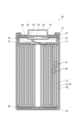
- FIG. 1 is a longitudinal sectional view illustrating a schematic diagram of an example of a lithium secondary battery according to an embodiment of the present disclosure.
- FIG. 2 is a cross-sectional view that illustrates a schematic diagram of a portion of the lithium secondary battery illustrated in FIG. 1 .
- FIG. 11 is a top view showing an example of a spacer pattern.
- FIG. 4 is a partially enlarged view of FIG. 3 .
- FIG. 11 is a top view showing another example of a spacer pattern.
- FIG. 11 is a top view showing another example of a spacer pattern.
- the lithium secondary battery according to the embodiment of the present disclosure includes a positive electrode, a negative electrode, a separator disposed between the positive electrode and the negative electrode, and a non-aqueous electrolyte.
- the negative electrode lithium metal is precipitated during charging, and the lithium metal is dissolved during discharging.
- the negative electrode has at least a negative electrode current collector, and the lithium metal is precipitated on the negative electrode current collector.
- the non-aqueous electrolyte has lithium ion conductivity.
- the lithium secondary battery is also called a lithium metal secondary battery.
- lithium secondary batteries for example, 70% or more of the rated capacity is achieved by the deposition and dissolution of lithium metal.
- the movement of electrons at the negative electrode during charging and discharging is mainly due to the deposition and dissolution of lithium metal at the negative electrode.
- 70-100% (for example, 80-100% or 90-100%) of the movement of electrons (current from another perspective) at the negative electrode during charging and discharging is due to the deposition and dissolution of lithium metal.
- the negative electrode of a lithium secondary battery is different from a negative electrode in which the movement of electrons at the negative electrode during charging and discharging is mainly due to the absorption and release of lithium ions by the negative electrode active material (such as graphite).
- each row it is desirable that the multiple cross sections of the first convex portions are arranged as orderly as possible. This allows the first convex portions to overlap with a sufficient overlap width.
- the greater the overlap width between the first convex portions the more enhanced the function of the spacer layer. In other words, the function of ensuring space for lithium to precipitate is improved.
- FIG. 1A(a) shows a schematic longitudinal section of the electrode group. Multiple cross sections of the first protrusions 53 are lined up in the second direction (radial direction) to form rows (L). One row (L) is formed in the region from the winding axis (center) to the circumferential surface of the longitudinal section of the electrode group. In the longitudinal section of the electrode group, multiple rows (L) are observed spaced apart (S) along the first direction.
- separator (A) the separator having the above configuration
- lithium secondary battery (B) the lithium secondary battery having the above configuration
- Separator (A) is used in lithium secondary battery (B).
- the main role of the spacer layer is to form a space in which lithium metal is deposited. By accommodating lithium metal in the space provided by the spacer layer, the expansion of the negative electrode during charging is suppressed.
- the function of the spacer layer is improved, the function of securing space for lithium to precipitate is improved, swelling of the electrode group is significantly suppressed, and the capacity retention rate of the lithium secondary battery is significantly improved.
- the A region facing the first convex portion is arranged on the separator in as uniform and dispersed a state as possible. This makes it possible to reduce the number of places where lithium metal can precipitate locally while suppressing an increase in internal resistance, and makes it easier to limit the amount of isolated lithium metal to as small an amount as possible.
- the separator, positive electrode, and negative electrode are strip-shaped with long and short sides. When the length (width) of the short side of the strip-shaped separator is L, and a circular region with a diameter of any L/3 is set on the surface of the separator, it is desirable that both A region and B region always coexist in such a circular region.
- the C region facing the second convex portion is arranged on the separator in as uniform and dispersed a state as possible. This increases the effect of reinforcing the separator and makes it easier to suppress the occurrence of wrinkles.
- L the length of the short side direction of the strip-shaped separator
- a circular region having a diameter of any L/3 or even L/5 is set on the surface of the separator, it is desirable that such a circular region always coexists with the C region and the D region.
- the first convex portion and the second convex portion may be formed on different main surfaces of the substrate layer. Specifically, a first spacer layer including the first convex portion may be provided on one main surface of the substrate layer, and a second spacer layer including the second convex portion may be provided on the other main surface of the substrate layer. From the viewpoint of improving the charge/discharge efficiency or cycle characteristics, it is more desirable to provide the first spacer layer on the main surface of the substrate layer facing the positive electrode, and from the viewpoint of improving the safety of the battery, it is more desirable to provide the first spacer layer on the main surface of the substrate layer facing the negative electrode.
- the dispersion liquid containing the spacer material contains, for example, insulating particles, a binder resin, and a thickener.
- the spacer formed from the dispersion liquid contains insulating particles, a binder resin, and a thickener.
- the dispersion medium of the dispersion liquid is not particularly limited, but may be, for example, water, an organic solvent, or a mixture of water and an organic solvent.
- an organic solvent for example, N-methyl-2-pyrrolidone (NMP) may be used. Among these, the use of water is preferable in terms of reducing the environmental impact.
- the shape of the insulating particles is not particularly limited, but may be spherical. However, spherical does not mean a strict perfect sphere, but a shape without sharp corners, with an aspect ratio (maximum diameter/maximum diameter in the direction perpendicular to the maximum diameter) in the range of, for example, 1 to 3.
- the median diameter (i.e., average particle diameter) in the volume-based particle size distribution of the insulating particles may be 1.0 ⁇ m to 10 ⁇ m.
- the median diameter is the particle diameter when the cumulative volume is 50%.
- the median diameter of the insulating particles may be 1.0 ⁇ m to 2 ⁇ m.
- the insulating particles in the dispersion liquid tend to maintain a stable dispersion state, and the dispersion state is maintained even after application to the base layer, making it easy to form a spacer layer with a homogeneous morphology.
- the volume resistivity of the insulating particles may be, for example, 1.0 ⁇ 10 8 ⁇ cm or more.
- the volume resistivity of the insulating particles may be even higher, for example, 1.0 ⁇ 10 10 ⁇ cm or more.
- the volume resistivity can be measured by a four-probe method.
- the insulating particles may be pressurized at 204 kgf/cm 2 and measured using a powder resistivity measuring device (for example, Loresta SP manufactured by Nitto Seiko Analytech Co., Ltd.).
- Insulating particles include inorganic particles such as metal oxides, metal hydroxides, metal nitrides, metal carbides, and metal sulfides.
- Metal oxides include aluminum oxide (alumina, boehmite), magnesium oxide, titanium oxide (titania), zirconium oxide, and silicon oxide (silica).
- Metal hydroxides include aluminum hydroxide.
- Metal nitrides include silicon nitride, aluminum nitride, boron nitride, and titanium nitride.
- Metal carbides include silicon carbide and boron carbide.
- Metal sulfides include barium sulfate. Minerals such as aluminosilicates, layered silicates, barium titanate, and strontium titanate may also be used. Of these, it is preferable to use alumina, silica, titania, and the like.
- the content of the insulating particles in the spacer layer is, for example, less than 80 volume %, and preferably 50 to 70 volume %.
- the content (volume ratio) of the insulating particles in the spacer may be determined by observing the cross section of the spacer layer with a transmission electron microscope (TEM), taking a TEM image, calculating the total area surrounded by the contours of the insulating particles in any 10 ⁇ m2 visual field, and calculating the volume ratio as the ratio of the calculated total area to the area of the visual field. In this case, it is preferable to determine the volume ratio in three or more visual fields and calculate the average value.
- TEM transmission electron microscope
- the amount of binder resin may be, for example, 20 to 80 parts by volume, 20 to 70 parts by volume, 20 to 50 parts by volume, or 25 to 40 parts by volume per 100 parts by volume of insulating particles. In this range, it is easy to increase the mechanical strength of the spacer layer and to increase the bonding strength between the base layer and the spacer layer.
- the thickener may contain, for example, at least one selected from the group consisting of carboxymethylcellulose and carboxymethylcellulose salts (hereinafter, at least one selected from the group consisting of carboxymethylcellulose and carboxymethylcellulose salts is also referred to as "CMC").
- carboxymethylcellulose salt it is obtained using sodium salt, lithium salt, potassium salt, ammonium salt, etc.
- carboxymethylcellulose salt contains sodium salt.
- the dispersion medium of the spacer material dispersion liquid may contain water.
- 50% by mass or more of the dispersion medium may be water, or 70% by mass or more, 80% by mass or more, or 90% by mass or more of the dispersion medium may be water.
- the amount of CMC may be, for example, 0.5 to 5 parts by volume, or 1 to 3 parts by volume, per 100 parts by volume of insulating particles. By using CMC within this range, it is possible to achieve a sufficient thickening effect of the CMC.
- the substrate layer is made of a porous sheet having ion permeability and insulation properties.
- the porous sheet include a microporous thin film, a woven fabric, and a nonwoven fabric.
- the material of the porous sheet is not particularly limited, but may be a polymeric material.
- the polymeric material include an olefin resin, a polyamide resin, and cellulose.
- the olefin resin include polyethylene, polypropylene, and a copolymer of ethylene and propylene.
- the substrate layer may contain an additive as necessary. Examples of the additive include an inorganic filler.
- the thickness of the substrate layer is not particularly limited, but is, for example, 5 ⁇ m or more and 20 ⁇ m or less, and more preferably 10 ⁇ m or more and 20 ⁇ m or less.
- the substrate layer may include a porous sheet and a composite material layer.
- the composite material layer may be formed on one or both main surfaces of the porous sheet.
- the composite material layer is a layer that allows lithium ions to pass through.
- the thickness of the composite material layer may be 5% to 50% of the total thickness of the separator.
- the composite material layer includes a resin material and inorganic particles.
- the inorganic particles may include first particles and/or second particles.
- the first particles are particles of a phosphate containing lithium.
- the first particles have the effect of suppressing heat generation in the battery under abnormal conditions.
- the second particles are particles other than the first particles.
- the composite material layer is formed on only one main surface of the porous sheet, it is desirable to provide the composite material layer on the main surface of the porous sheet facing the positive electrode.
- the composite material layer on the positive electrode side it is possible to prevent the porous sheet from deteriorating due to oxidation reactions.
- the composite material layer on the negative electrode side it is possible to prevent the porous sheet from deteriorating due to reduction reactions.
- the phosphate constituting the first particles may be at least one selected from the group consisting of lithium phosphate (Li 3 PO 4 ), dilithium hydrogen phosphate (Li 2 HPO 4 ), and lithium dihydrogen phosphate (LiH 2 PO 4 ).
- lithium phosphate is preferred because it is highly effective in suppressing heat generation in the battery under abnormal conditions.
- the median diameter in the volume-based particle size distribution of the first particles may be 0.1 ⁇ m to 1.0 ⁇ m.
- the median diameter in the particle size distribution based on volume of the particles can be measured, for example, by a laser diffraction/scattering type particle size distribution measuring device (for example, Microtrack manufactured by Nikkiso Co., Ltd.).
- the cross section of the base layer can be observed with a transmission electron microscope (TEM), a TEM image can be taken, the area enclosed by the outlines of any 100 first particles or second particles can be calculated, the diameter of an equivalent circle (perfect circle) having the same area as the calculated area can be calculated, and the average diameter of the 100 equivalent circles can be calculated.
- TEM transmission electron microscope
- a polymeric material that has higher heat resistance than the material of the porous sheet.
- a polymeric material preferably contains at least one selected from the group consisting of aromatic polyamides, aromatic polyimides, and aromatic polyamideimides. These are known as polymeric materials with high heat resistance. From the viewpoint of heat resistance, aramids, namely meta-aramids (meta-fully aromatic polyamides) and para-aramids (para-fully aromatic polyamides), are preferred.
- the inorganic particle content in the composite layer may be in the range of 50% by mass to 99% by mass (e.g., in the range of 85% by mass to 99% by mass).
- the negative electrode may include a lithium ion storage layer (a layer that develops capacity by the absorption and release of lithium ions by the negative electrode active material (such as graphite)) supported on the negative electrode current collector.
- the open circuit potential of the negative electrode when fully charged may be 70 mV or less relative to lithium metal (lithium dissolution and deposition potential). If the open circuit potential of the negative electrode when fully charged is 70 mV or less relative to lithium metal, lithium metal is present on the surface of the lithium ion storage layer when fully charged. In other words, the negative electrode develops capacity by the deposition and dissolution of lithium metal.
- fully charged refers to a state in which the battery is charged to a charging state of, for example, 0.98 x C or more, where C is the rated capacity of the battery.
- the open circuit potential of the negative electrode when fully charged can be measured by disassembling a fully charged battery under an argon atmosphere, removing the negative electrode, assembling a cell with lithium metal as the counter electrode, and then measuring the potential.
- the non-aqueous electrolyte of the cell may have the same composition as the non-aqueous electrolyte in the disassembled battery.
- the lithium ion storage layer is a layer of a negative electrode mixture containing a negative electrode active material.
- the negative electrode mixture may also contain a binder, a thickener, a conductive agent, etc.
- Examples of negative electrode active materials include carbonaceous materials, Si-containing materials, and Sn-containing materials.
- the negative electrode may contain one type of negative electrode active material, or may contain a combination of two or more types.
- Examples of carbonaceous materials include graphite, easily graphitized carbon (soft carbon), and non-graphitizable carbon (hard carbon).
- the conductive material is, for example, a carbon material.
- carbon materials include carbon black, acetylene black, ketjen black, carbon nanotubes, and graphite.
- the negative electrode current collector can be a conductive sheet.
- conductive sheets include foil and film.
- the material of the negative electrode current collector may be any conductive material other than lithium metal and lithium alloy.
- the conductive material may be a metallic material such as a metal or an alloy.
- the conductive material is preferably a material that does not react with lithium. More specifically, a material that does not form an alloy or an intermetallic compound with lithium is preferable. Examples of such conductive materials include copper (Cu), nickel (Ni), iron (Fe), and alloys containing these metal elements, or graphite with the basal surface preferentially exposed.
- alloys include copper alloys and stainless steel (SUS). Among these, copper and/or copper alloys, which have high conductivity, are preferable.
- the positive electrode includes, for example, a positive electrode current collector and a positive electrode mixture layer supported by the positive electrode current collector.
- the positive electrode mixture layer includes, for example, a positive electrode active material, a conductive material, and a binder.
- the positive electrode mixture layer may be formed on only one side of the positive electrode current collector, or may be formed on both sides.
- the positive electrode is obtained, for example, by applying a positive electrode mixture slurry including a positive electrode active material, a conductive material, and a binder to both sides of the positive electrode current collector, drying the coating, and then rolling.
- the positive electrode active material is a material that absorbs and releases lithium ions.
- positive electrode active materials include lithium-containing transition metal oxides, transition metal fluorides, polyanions, fluorinated polyanions, transition metal sulfides, etc. Among these, lithium-containing transition metal oxides are preferred because of their low manufacturing costs and high average discharge voltage.
- the transition metal elements contained in the lithium-containing transition metal oxide include Sc, Ti, V, Cr, Mn, Fe, Co, Ni, Cu, Y, Zr, W, etc.
- the lithium-containing transition metal oxide may contain one type of transition metal element, or may contain two or more types.
- the transition metal element may be Co, Ni, and/or Mn.
- the lithium-containing transition metal oxide may contain one or more typical elements as necessary.
- the typical elements include Mg, Al, Ca, Zn, Ga, Ge, Sn, Sb, Pb, Bi, etc.
- the typical element may be Al, etc.
- the thickness of the positive electrode current collector is not particularly limited, and is, for example, 5 ⁇ m or more and 300 ⁇ m or less.
- the gel electrolyte contains a lithium salt and a matrix polymer, or a lithium salt, a non-aqueous solvent, and a matrix polymer.
- a matrix polymer for example, a polymer material that absorbs the non-aqueous solvent and gels is used. Examples of the polymer material include fluororesin, acrylic resin, polyether resin, and polyethylene oxide.
- a liquid non-aqueous electrolyte is prepared by dissolving a lithium salt in a non-aqueous solvent. When the lithium salt dissolves in the non-aqueous solvent, lithium ions and anions are produced.
- anion examples include BF 4 - , ClO 4 - , PF 6 - , CF 3 SO 3 - , CF 3 CO 2 - , anions of imides, and anions of oxalate complexes.
- the anion of the oxalate complex may contain boron and/or phosphorus.
- the non-aqueous electrolyte preferably contains at least an anion of an oxalate complex, and more preferably contains an anion of an oxalate complex having fluorine.
- the interaction between the oxalate complex anion having fluorine and lithium makes it easier for the lithium metal to be precipitated uniformly in the form of fine particles. This makes it easier to suppress localized precipitation of the lithium metal.
- the oxalate complex anion having fluorine may be combined with another anion.
- the other anion may be an anion of PF 6 - and/or an imide.
- non-aqueous solvents examples include esters, ethers, nitriles, amides, and halogen-substituted derivatives thereof.
- the non-aqueous electrolyte may contain one or more of these non-aqueous solvents.
- halogen-substituted derivatives include fluorides.
- the non-aqueous electrolyte may contain an additive.
- the additive may form a coating on the negative electrode.
- the coating derived from the additive is formed on the negative electrode, which makes it easier to suppress the formation of dendrites.
- examples of such additives include vinylene carbonate, FEC, vinyl ethyl carbonate (VEC), etc.
- the lower valve body 23 has an air vent hole (not shown). Therefore, when the internal pressure of the battery case rises due to abnormal heat generation or the like, the upper valve body 25 bulges toward the cap 26 and separates from the lower valve body 23. This cuts off the electrical connection between the lower valve body 23 and the upper valve body 25. If the internal pressure rises further, the upper valve body 25 breaks and gas is discharged from the opening formed in the cap 26.
- the electrode group 14 includes a positive electrode 11, a negative electrode 12, and a separator 50.
- the separator 50 has a base layer 50A and a spacer layer 50B.
- the positive electrode 11, the negative electrode 12, and the separator 50 are all strip-shaped.
- the electrode group 14 having multiple turns is formed by winding the positive electrode 11, the negative electrode 12, and the separator 50 so that the separator 50 is disposed between the positive electrode 11 and the negative electrode 12.
- the positive electrode 11 includes a positive electrode collector 11a and a positive electrode composite layer 11b formed on both sides of the positive electrode collector 11a.
- the positive electrode collector 11a is electrically connected to a cap 26 that functions as a positive electrode terminal via a positive electrode lead 19.
- the negative electrode 12 is shown as a negative electrode (negative electrode current collector) on which lithium metal has not been precipitated.
- the negative electrode 12 is electrically connected to the case body 15, which functions as the negative electrode terminal, via the negative electrode lead 20.
Landscapes
- Chemical & Material Sciences (AREA)
- Chemical Kinetics & Catalysis (AREA)
- Electrochemistry (AREA)
- General Chemical & Material Sciences (AREA)
- Engineering & Computer Science (AREA)
- Manufacturing & Machinery (AREA)
- Materials Engineering (AREA)
- Secondary Cells (AREA)
- Cell Separators (AREA)
- Battery Electrode And Active Subsutance (AREA)
Priority Applications (3)
| Application Number | Priority Date | Filing Date | Title |
|---|---|---|---|
| EP23911782.3A EP4645509A1 (en) | 2022-12-27 | 2023-12-15 | Lithium secondary battery and separator |
| JP2024567493A JPWO2024143001A1 (https=) | 2022-12-27 | 2023-12-15 | |
| CN202380088717.3A CN120419011A (zh) | 2022-12-27 | 2023-12-15 | 锂二次电池和隔膜 |
Applications Claiming Priority (2)
| Application Number | Priority Date | Filing Date | Title |
|---|---|---|---|
| JP2022210611 | 2022-12-27 | ||
| JP2022-210611 | 2022-12-27 |
Publications (1)
| Publication Number | Publication Date |
|---|---|
| WO2024143001A1 true WO2024143001A1 (ja) | 2024-07-04 |
Family
ID=91717324
Family Applications (1)
| Application Number | Title | Priority Date | Filing Date |
|---|---|---|---|
| PCT/JP2023/045073 Ceased WO2024143001A1 (ja) | 2022-12-27 | 2023-12-15 | リチウム二次電池およびセパレータ |
Country Status (4)
| Country | Link |
|---|---|
| EP (1) | EP4645509A1 (https=) |
| JP (1) | JPWO2024143001A1 (https=) |
| CN (1) | CN120419011A (https=) |
| WO (1) | WO2024143001A1 (https=) |
Citations (7)
| Publication number | Priority date | Publication date | Assignee | Title |
|---|---|---|---|---|
| WO2005022674A1 (ja) * | 2003-08-29 | 2005-03-10 | Ube Industries, Ltd. | 電池用セパレータ及びリチウム二次電池 |
| JP2010086775A (ja) * | 2008-09-30 | 2010-04-15 | Toshiba Corp | 二次電池 |
| JP2019212609A (ja) * | 2018-05-31 | 2019-12-12 | パナソニックIpマネジメント株式会社 | リチウム二次電池 |
| JP2019212608A (ja) * | 2018-05-31 | 2019-12-12 | パナソニックIpマネジメント株式会社 | リチウム二次電池 |
| WO2021086810A1 (en) * | 2019-10-29 | 2021-05-06 | Daramic, Llc | Lead acid separators, battery systems and their manufacturing methods. |
| WO2021192645A1 (ja) | 2020-03-27 | 2021-09-30 | パナソニックIpマネジメント株式会社 | リチウム二次電池 |
| WO2022045127A1 (ja) * | 2020-08-31 | 2022-03-03 | パナソニックIpマネジメント株式会社 | リチウム二次電池 |
-
2023
- 2023-12-15 WO PCT/JP2023/045073 patent/WO2024143001A1/ja not_active Ceased
- 2023-12-15 JP JP2024567493A patent/JPWO2024143001A1/ja active Pending
- 2023-12-15 CN CN202380088717.3A patent/CN120419011A/zh active Pending
- 2023-12-15 EP EP23911782.3A patent/EP4645509A1/en active Pending
Patent Citations (7)
| Publication number | Priority date | Publication date | Assignee | Title |
|---|---|---|---|---|
| WO2005022674A1 (ja) * | 2003-08-29 | 2005-03-10 | Ube Industries, Ltd. | 電池用セパレータ及びリチウム二次電池 |
| JP2010086775A (ja) * | 2008-09-30 | 2010-04-15 | Toshiba Corp | 二次電池 |
| JP2019212609A (ja) * | 2018-05-31 | 2019-12-12 | パナソニックIpマネジメント株式会社 | リチウム二次電池 |
| JP2019212608A (ja) * | 2018-05-31 | 2019-12-12 | パナソニックIpマネジメント株式会社 | リチウム二次電池 |
| WO2021086810A1 (en) * | 2019-10-29 | 2021-05-06 | Daramic, Llc | Lead acid separators, battery systems and their manufacturing methods. |
| WO2021192645A1 (ja) | 2020-03-27 | 2021-09-30 | パナソニックIpマネジメント株式会社 | リチウム二次電池 |
| WO2022045127A1 (ja) * | 2020-08-31 | 2022-03-03 | パナソニックIpマネジメント株式会社 | リチウム二次電池 |
Non-Patent Citations (1)
| Title |
|---|
| See also references of EP4645509A1 |
Also Published As
| Publication number | Publication date |
|---|---|
| EP4645509A1 (en) | 2025-11-05 |
| CN120419011A (zh) | 2025-08-01 |
| JPWO2024143001A1 (https=) | 2024-07-04 |
Similar Documents
| Publication | Publication Date | Title |
|---|---|---|
| CN112673504B (zh) | 锂二次电池 | |
| JP7813987B2 (ja) | リチウム二次電池 | |
| JP7194940B2 (ja) | リチウム二次電池 | |
| US20240194951A1 (en) | Lithium secondary battery | |
| JP7289072B2 (ja) | リチウム二次電池 | |
| JP7113227B2 (ja) | リチウム二次電池 | |
| JP2019212608A (ja) | リチウム二次電池 | |
| JP7113226B2 (ja) | リチウム二次電池 | |
| WO2024143000A1 (ja) | リチウム二次電池およびセパレータ | |
| JP2019212605A (ja) | リチウム二次電池 | |
| JP7162174B2 (ja) | リチウム二次電池 | |
| WO2024070854A1 (ja) | リチウム二次電池、リチウム二次電池用スペーサ、スペーサ材料およびリチウム二次電池用セパレータとスペーサの一体化物 | |
| WO2024048136A1 (ja) | リチウム二次電池および複合部材 | |
| WO2023234223A1 (ja) | リチウム二次電池および複合部材 | |
| WO2024048135A1 (ja) | リチウム二次電池および複合部材 | |
| WO2024143001A1 (ja) | リチウム二次電池およびセパレータ | |
| JP7162175B2 (ja) | リチウム二次電池 | |
| WO2025022868A1 (ja) | リチウム二次電池およびセパレータ | |
| WO2025022867A1 (ja) | リチウム二次電池およびセパレータ | |
| WO2024181086A1 (ja) | リチウム二次電池 | |
| EP4675740A1 (en) | Lithium secondary battery | |
| WO2025070578A1 (ja) | 二次電池 | |
| WO2026048847A1 (ja) | 二次電池 | |
| WO2025047688A1 (ja) | リチウム二次電池 | |
| WO2024143005A1 (ja) | リチウム二次電池およびセパレータ |
Legal Events
| Date | Code | Title | Description |
|---|---|---|---|
| 121 | Ep: the epo has been informed by wipo that ep was designated in this application |
Ref document number: 23911782 Country of ref document: EP Kind code of ref document: A1 |
|
| WWE | Wipo information: entry into national phase |
Ref document number: 202380088717.3 Country of ref document: CN |
|
| WWE | Wipo information: entry into national phase |
Ref document number: 2024567493 Country of ref document: JP |
|
| WWE | Wipo information: entry into national phase |
Ref document number: 2023911782 Country of ref document: EP |
|
| NENP | Non-entry into the national phase |
Ref country code: DE |
|
| WWP | Wipo information: published in national office |
Ref document number: 202380088717.3 Country of ref document: CN |
|
| ENP | Entry into the national phase |
Ref document number: 2023911782 Country of ref document: EP Effective date: 20250728 |
|
| ENP | Entry into the national phase |
Ref document number: 2023911782 Country of ref document: EP Effective date: 20250728 |
|
| WWP | Wipo information: published in national office |
Ref document number: 2023911782 Country of ref document: EP |