WO2024142856A1 - 歩行者保護用エアバッグ装置 - Google Patents
歩行者保護用エアバッグ装置 Download PDFInfo
- Publication number
- WO2024142856A1 WO2024142856A1 PCT/JP2023/044044 JP2023044044W WO2024142856A1 WO 2024142856 A1 WO2024142856 A1 WO 2024142856A1 JP 2023044044 W JP2023044044 W JP 2023044044W WO 2024142856 A1 WO2024142856 A1 WO 2024142856A1
- Authority
- WO
- WIPO (PCT)
- Prior art keywords
- pedestrian protection
- airbag device
- airbag cushion
- vehicle
- protection airbag
- Prior art date
- Legal status (The legal status is an assumption and is not a legal conclusion. Google has not performed a legal analysis and makes no representation as to the accuracy of the status listed.)
- Ceased
Links
Images






Classifications
-
- B—PERFORMING OPERATIONS; TRANSPORTING
- B60—VEHICLES IN GENERAL
- B60R—VEHICLES, VEHICLE FITTINGS, OR VEHICLE PARTS, NOT OTHERWISE PROVIDED FOR
- B60R21/00—Arrangements or fittings on vehicles for protecting or preventing injuries to occupants or pedestrians in case of accidents or other traffic risks
- B60R21/34—Protecting non-occupants of a vehicle, e.g. pedestrians
- B60R21/36—Protecting non-occupants of a vehicle, e.g. pedestrians using airbags
Definitions
- Pedestrian protection airbag devices that deploy an airbag cushion around the rear end of the bonnet are used to protect the head of a pedestrian who rides up onto the bonnet (hood panel) when a vehicle collides with a pedestrian.
- one such pedestrian protection airbag device deploys a pedestrian airbag cushion mounted at the boundary between the bonnet and windshield (front glass) to cover both the A-pillar and windshield, which are located rearward of the boundary, and the rear end of the bonnet, which is located forward of the boundary (see, for example, Patent Document 1).
- the airbag cushion inflates in the narrow area directly above the windshield and the internal pressure becomes high, this can cause the airbag cushion to strongly interfere with surrounding parts such as the windshield and wipers, which can ultimately damage the windshield.
- the speed at which the airbag can protect the impact point at the very front of the vehicle within the area that it must protect is particularly important, but there is a problem that the airbag may not be able to deploy in time.
- the area that must be protected has been expanding year by year, and the contact time has been getting earlier in line with exterior design trends, so there is a growing tendency for the airbag to not be able to deploy in time if the existing structure is used.
- the present invention aims to provide a pedestrian protection airbag device that is designed to prevent the airbag cushion from interfering strongly with the windshield (front glass) and surrounding parts during the initial stage of inflation and deployment of the airbag cushion, and to deploy in time for the required deployment time at the forward-most impact point of the vehicle.
- One aspect of the present invention is a pedestrian protection airbag device including an airbag cushion that inflates during a vehicle collision and deploys from a boundary between a bonnet and a windshield of the vehicle to protect a pedestrian or the like who has collided with the vehicle, a temporary fastening portion that temporarily fastens a portion of the airbag cushion so as to divide a chamber that forms an internal space of the airbag cushion into a front inflating portion that inflates at an upper portion of the bonnet and a rear inflating portion that inflates near a lower end portion of the windshield in an initial stage of inflation and deployment of the airbag cushion; an inflator that ejects gas toward the front inflation portion so as to inflate the front inflation portion earlier than the rear inflation portion;
- the present invention relates to an airbag device for pedestrian protection.
- the temporary fastening portion may be formed by sewing a part of the airbag cushion to a temporary sewing portion.
- the temporary stitching portion may be provided by folding a portion of the airbag cushion outward and sewing the folded portion.
- the temporary stitching may be provided using sewing thread that may break during the airbag cushion inflation and deployment.
- the temporary stitching portion may be provided along the vehicle width direction.
- the inflator may be installed so as to eject gas in the direction in which the forward inflatable portion deploys.
- the inflator may be installed so as to eject gas diagonally upward from the vehicle.
- FIG. 1 is an image showing the airbag cushion after folding. 1 is an image showing the vicinity of an opening of an airbag cushion. 13 is an image showing the vicinity of a temporary stitching portion inside an airbag cushion.
- FIG. 2 is a diagram showing a state in which an inflator is attached inside an airbag cushion.
- FIG. 2 is a top view showing a schematic diagram of an inflated and deployed airbag cushion.
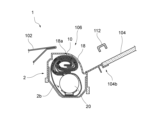
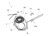
- FIG. 13 is a schematic diagram showing a pedestrian protection airbag device according to another embodiment of the present invention. 1 is a schematic diagram showing a pedestrian protection airbag device in an initial stage of inflation and deployment of an airbag cushion; 13 is a schematic diagram showing the pedestrian protection airbag device at a stage where the airbag cushion is further inflated and deployed.
- FIG. 1 is a schematic diagram showing a pedestrian protection airbag device in an initial stage of inflation and deployment of an airbag cushion
- 13 is a schematic diagram showing the pedestrian protection airbag device at a stage where the airbag cushion is further inflated and deployed.
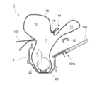
- FIG. 1 is a schematic diagram showing a pedestrian protection airbag device at a stage when an airbag cushion is fully inflated and deployed;
- FIG. 13 is a diagram showing a state in which a pedestrian's head is protected by an airbag cushion that is inflated and deployed during a vehicle collision.
- the primary subjects of protection for the pedestrian protection airbag device 1 according to the embodiment are pedestrians, and the following description will be given taking pedestrians as an example.
- the subjects of protection also include, for example, people riding bicycles (cyclists), as well as people riding motorbikes, skateboards, kick scooters, and the like.
- “At the time of a vehicle collision” refers primarily to a time when the vehicle 100 collides with a pedestrian (indicated by reference symbol 200 in FIG. 16) (see FIG. 16). Whether or not the vehicle 100 has collided, and whether or not the collision is with a pedestrian, can be determined by a known method, for example, based on detection by a sensor (such as a pressure sensor or an acceleration sensor) mounted on the bumper of the vehicle.
- a sensor such as a pressure sensor or an acceleration sensor
- “Outside the vehicle cabin” means the outside of the vehicle interior 110 of the vehicle 100 (see FIG. 16).
- the pedestrian protection airbag device 1 is mounted near the boundary 106 between the bonnet 102 and the windshield 104 of the vehicle 100, and the airbag cushion 10 inflates and deploys from near the boundary 106 toward the outside of the vehicle.
- the airbag cushion 10 thus inflated and deployed covers the rear side of the bonnet 102, the lower front end of the windshield 104, and at least the lower parts of the left and right A-pillars 108, protecting the head of a pedestrian who collides with the vehicle 100 (see FIG. 11 and FIG. 16).
- the coverage area of the airbag cushion 10 on the A-pillar 108 may be extended to reach the top of the A-pillar 108, if necessary.
- the airbag cushion 10 is provided with a temporary stitching portion (temporary fastening portion) 14.
- the temporary stitching portion 14 temporarily fastens a portion of the airbag cushion 10 so as to divide the area or partitioned space (referred to as a chamber in this specification and indicated by the reference symbol 11) that forms the internal space of the airbag cushion 10 into a front expansion portion 12 and a rear expansion portion 13 at least in the initial stage of the inflation and deployment of the airbag cushion 10.
- the front expansion portion 12 and the rear expansion portion 13 respectively refer to the front and rear portions of the chamber 11 of the airbag cushion 10 that is inflated and deployed.
- the front expansion portion 12 is the portion that mainly deploys above the bonnet 102
- the rear expansion portion 13 is the portion that mainly deploys near the lower end portion 104b of the windshield 104 (see Figures 3, 4, etc.).
- the airbag cushion 10 is first folded in the order of (A), (B), and (C) in Fig. 6 (see Fig. 6).
- the opening 15 into which the inflator 20 is inserted is not closed (see Fig. 6 (C)), and the opening 15 remains open even after folding as described above.
- the chamber 11 of the airbag cushion 10 is divided into a front inflation section (portion to become) 12 and a rear inflation section (portion to become) 13 by the temporary stitching section 14, and the inflator 20 ejects gas 22 toward the front inflation section 12 so as to cause the front inflation section 12 to deploy earlier than the rear inflation section 13, making it possible to deploy the front inflation section 12 first.
- This is a structural mechanism that allows inflation and deployment in two stages by sequentially increasing the internal pressure, and by intentionally delaying the deployment of the rear inflation section 13, it is possible to prevent the internal pressure of the airbag cushion 10 from becoming too high in the narrow area directly above the windshield 104.
- a pedestrian protection airbag device according to claim 2, wherein the temporary stitching is provided using a sewing thread that may break during the course of the airbag cushion being inflated and deployed.
Landscapes
- Engineering & Computer Science (AREA)
- Mechanical Engineering (AREA)
- Air Bags (AREA)
- Superstructure Of Vehicle (AREA)
Priority Applications (3)
| Application Number | Priority Date | Filing Date | Title |
|---|---|---|---|
| EP23911637.9A EP4644190A1 (en) | 2022-12-26 | 2023-12-08 | Pedestrian protection airbag device |
| JP2024567403A JP7809224B2 (ja) | 2022-12-26 | 2023-12-08 | 歩行者保護用エアバッグ装置 |
| CN202380088911.1A CN120418130A (zh) | 2022-12-26 | 2023-12-08 | 行人保护用安全气囊装置 |
Applications Claiming Priority (2)
| Application Number | Priority Date | Filing Date | Title |
|---|---|---|---|
| JP2022208348 | 2022-12-26 | ||
| JP2022-208348 | 2022-12-26 |
Publications (1)
| Publication Number | Publication Date |
|---|---|
| WO2024142856A1 true WO2024142856A1 (ja) | 2024-07-04 |
Family
ID=91717587
Family Applications (1)
| Application Number | Title | Priority Date | Filing Date |
|---|---|---|---|
| PCT/JP2023/044044 Ceased WO2024142856A1 (ja) | 2022-12-26 | 2023-12-08 | 歩行者保護用エアバッグ装置 |
Country Status (4)
| Country | Link |
|---|---|
| EP (1) | EP4644190A1 (https=) |
| JP (1) | JP7809224B2 (https=) |
| CN (1) | CN120418130A (https=) |
| WO (1) | WO2024142856A1 (https=) |
Citations (6)
| Publication number | Priority date | Publication date | Assignee | Title |
|---|---|---|---|---|
| JP2006327360A (ja) * | 2005-05-25 | 2006-12-07 | Toyoda Gosei Co Ltd | 歩行者用エアバッグ装置 |
| JP2008230520A (ja) * | 2007-03-22 | 2008-10-02 | Takata Corp | 車外用エアバッグ装置 |
| JP2015157616A (ja) * | 2013-04-26 | 2015-09-03 | タカタ株式会社 | エアバッグ装置及びエアバッグの折り畳み方法 |
| JP6592987B2 (ja) | 2015-06-29 | 2019-10-23 | Joyson Safety Systems Japan株式会社 | 歩行者用エアバッグ装置 |
| JP2022121314A (ja) * | 2021-02-08 | 2022-08-19 | 豊田合成株式会社 | 歩行者用エアバッグ装置 |
| JP2022121313A (ja) * | 2021-02-08 | 2022-08-19 | 豊田合成株式会社 | 歩行者用エアバッグ装置 |
-
2023
- 2023-12-08 WO PCT/JP2023/044044 patent/WO2024142856A1/ja not_active Ceased
- 2023-12-08 CN CN202380088911.1A patent/CN120418130A/zh active Pending
- 2023-12-08 JP JP2024567403A patent/JP7809224B2/ja active Active
- 2023-12-08 EP EP23911637.9A patent/EP4644190A1/en active Pending
Patent Citations (6)
| Publication number | Priority date | Publication date | Assignee | Title |
|---|---|---|---|---|
| JP2006327360A (ja) * | 2005-05-25 | 2006-12-07 | Toyoda Gosei Co Ltd | 歩行者用エアバッグ装置 |
| JP2008230520A (ja) * | 2007-03-22 | 2008-10-02 | Takata Corp | 車外用エアバッグ装置 |
| JP2015157616A (ja) * | 2013-04-26 | 2015-09-03 | タカタ株式会社 | エアバッグ装置及びエアバッグの折り畳み方法 |
| JP6592987B2 (ja) | 2015-06-29 | 2019-10-23 | Joyson Safety Systems Japan株式会社 | 歩行者用エアバッグ装置 |
| JP2022121314A (ja) * | 2021-02-08 | 2022-08-19 | 豊田合成株式会社 | 歩行者用エアバッグ装置 |
| JP2022121313A (ja) * | 2021-02-08 | 2022-08-19 | 豊田合成株式会社 | 歩行者用エアバッグ装置 |
Non-Patent Citations (1)
| Title |
|---|
| See also references of EP4644190A1 |
Also Published As
| Publication number | Publication date |
|---|---|
| CN120418130A (zh) | 2025-08-01 |
| JP7809224B2 (ja) | 2026-01-30 |
| EP4644190A1 (en) | 2025-11-05 |
| JPWO2024142856A1 (https=) | 2024-07-04 |
Similar Documents
| Publication | Publication Date | Title |
|---|---|---|
| US7073619B2 (en) | Vehicle frontal airbag system | |
| JP5529968B2 (ja) | カーテンエアバッグ | |
| JP6294952B2 (ja) | Icのための二重折りにして巻かれたクッション | |
| JP2005138749A (ja) | 歩行者等の保護装置 | |
| JP5856405B2 (ja) | カーテンエアバッグ | |
| JP7736492B2 (ja) | 歩行者保護エアバッグ装置 | |
| US20060125215A1 (en) | Airbag module | |
| CN216467674U (zh) | 用于车辆的车顶安全气囊 | |
| JP2007112371A (ja) | 乗員脚部拘束装置 | |
| JP5024251B2 (ja) | サイドエアバッグ装置 | |
| JP6330576B2 (ja) | 車両用カーテンエアバッグ装置 | |
| JP4037005B2 (ja) | サイドエアバッグ装置 | |
| KR20100041489A (ko) | 차량 운전석의 에어백쿠션 및 그 폴딩방법 | |
| JP4432699B2 (ja) | エアバッグ装置 | |
| JP6973343B2 (ja) | サイドエアバッグ装置 | |
| JP7809224B2 (ja) | 歩行者保護用エアバッグ装置 | |
| JPH07125605A (ja) | フードエアバッグ装置 | |
| JP2012062042A (ja) | カーテンエアバッグ | |
| JP7410329B2 (ja) | 歩行者保護用エアバッグ装置及びその製造方法 | |
| JP2024034304A (ja) | エアバッグドアおよびインパネロアの連結構造 | |
| KR101867061B1 (ko) | 자동차의 커튼 에어백 | |
| JP2001163159A (ja) | サイドエアバッグ装置 | |
| JP4595724B2 (ja) | 頭部保護エアバッグ装置 | |
| JP7793252B2 (ja) | 歩行者保護用エアバッグ装置 | |
| JPH10287195A (ja) | 側突用エアバッグ |
Legal Events
| Date | Code | Title | Description |
|---|---|---|---|
| 121 | Ep: the epo has been informed by wipo that ep was designated in this application |
Ref document number: 23911637 Country of ref document: EP Kind code of ref document: A1 |
|
| WWE | Wipo information: entry into national phase |
Ref document number: 2024567403 Country of ref document: JP |
|
| WWE | Wipo information: entry into national phase |
Ref document number: 202380088911.1 Country of ref document: CN |
|
| WWE | Wipo information: entry into national phase |
Ref document number: 2023911637 Country of ref document: EP |
|
| NENP | Non-entry into the national phase |
Ref country code: DE |
|
| WWP | Wipo information: published in national office |
Ref document number: 202380088911.1 Country of ref document: CN |
|
| ENP | Entry into the national phase |
Ref document number: 2023911637 Country of ref document: EP Effective date: 20250728 |
|
| ENP | Entry into the national phase |
Ref document number: 2023911637 Country of ref document: EP Effective date: 20250728 |
|
| WWP | Wipo information: published in national office |
Ref document number: 2023911637 Country of ref document: EP |