WO2024142152A1 - 光伝送路及び接続方法 - Google Patents
光伝送路及び接続方法 Download PDFInfo
- Publication number
- WO2024142152A1 WO2024142152A1 PCT/JP2022/047896 JP2022047896W WO2024142152A1 WO 2024142152 A1 WO2024142152 A1 WO 2024142152A1 JP 2022047896 W JP2022047896 W JP 2022047896W WO 2024142152 A1 WO2024142152 A1 WO 2024142152A1
- Authority
- WO
- WIPO (PCT)
- Prior art keywords
- optical fiber
- core optical
- fiber transmission
- transmission lines
- core
- Prior art date
- Legal status (The legal status is an assumption and is not a legal conclusion. Google has not performed a legal analysis and makes no representation as to the accuracy of the status listed.)
- Ceased
Links
Images

Classifications
-
- G—PHYSICS
- G02—OPTICS
- G02B—OPTICAL ELEMENTS, SYSTEMS OR APPARATUS
- G02B6/00—Light guides; Structural details of arrangements comprising light guides and other optical elements, e.g. couplings
- G02B6/10—Light guides; Structural details of arrangements comprising light guides and other optical elements, e.g. couplings of the optical waveguide type
-
- G—PHYSICS
- G02—OPTICS
- G02B—OPTICAL ELEMENTS, SYSTEMS OR APPARATUS
- G02B6/00—Light guides; Structural details of arrangements comprising light guides and other optical elements, e.g. couplings
- G02B6/02—Optical fibres with cladding with or without a coating
- G02B6/02042—Multicore optical fibres
-
- G—PHYSICS
- G02—OPTICS
- G02B—OPTICAL ELEMENTS, SYSTEMS OR APPARATUS
- G02B6/00—Light guides; Structural details of arrangements comprising light guides and other optical elements, e.g. couplings
- G02B6/24—Coupling light guides
- G02B6/26—Optical coupling means
- G02B6/35—Optical coupling means having switching means
-
- G—PHYSICS
- G02—OPTICS
- G02B—OPTICAL ELEMENTS, SYSTEMS OR APPARATUS
- G02B6/00—Light guides; Structural details of arrangements comprising light guides and other optical elements, e.g. couplings
- G02B6/24—Coupling light guides
- G02B6/36—Mechanical coupling means
- G02B6/38—Mechanical coupling means having fibre to fibre mating means
Definitions
- Figure 1 shows an example of connecting multiple multi-core optical fiber transmission lines.
- 103 indicates a multi-core optical fiber transmission line
- 106 indicates a core
- 107 indicates a marker.
- the optical transmission line of the present disclosure is A plurality of multi-core optical fiber transmission lines; two input/output devices arranged at both ends of the plurality of multi-core optical fiber transmission lines for inputting and outputting light to and from a plurality of cores of the multi-core optical fiber transmission lines; a switching connection device that is disposed between any of the multi-core optical fiber transmission lines and switches and connects each of the cores of the multi-core optical fiber transmission lines; Equipped with.
- the optical transmission line 100 of this embodiment includes a plurality of multi-core optical fiber transmission lines 103, two input/output devices 102, 104 arranged at both ends of the plurality of multi-core optical fiber transmission lines 103 for inputting and outputting light to the plurality of cores of the multi-core optical fiber transmission lines 103, and a switching connection device 110 arranged between the multi-core optical fiber transmission lines 103 and the input/output devices 104 for switching and connecting each core of the multi-core optical fiber transmission lines 103 to each core of the multi-core optical fiber of the input/output device 104.
- any cores of the multiple multi-core optical fiber transmission lines 103 are connected to each other, and at the other end of the multiple connected multi-core optical fiber transmission lines 103, a switching connection device 110 is used to switch and connect so that the channel of the input/output device 104 matches the channel of the input/output device 102.
- each channel 101 of the input/output device 102 and each channel 105 of the input/output device 104 can be made to correspond to the desired relationship.
- any cores of multiple multi-core optical fiber transmission lines 103 can be connected to each other, thereby shortening the connection time. This leads to cost reductions during the construction and operation of the optical transmission lines.
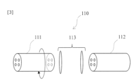
- FIG. 4 An example of the configuration of the switching connection device 110 of this embodiment is shown in FIG. 4.
- 110 is a switching connection device
- 111 and 112 are multi-core optical fibers
- 114 and 115 are ferrules.
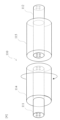
- the switching connection device 110 switches and connects each core arranged on a concentric circle of one multi-core optical fiber 111 to each core arranged on a concentric circle of the opposing other multi-core optical fiber 112 by rotating the one multi-core optical fiber 111 around its axis at the center.
- the ferrule 115 that houses the other multi-core optical fiber 112 is fixed, the far end of the one multi-core optical fiber 111 is fixed, and the ferrule 114 is rotated around the center of the one multi-core optical fiber 111.
- the end face of the ferrule 114 and the end face of the ferrule 115 are separated from each other, but it is preferable to bring the end faces as close as possible to each other.
- One multi-core optical fiber 111 may be connected to the input/output device 104 in FIG. 2, and the other multi-core optical fiber 112 may be connected to the multi-core optical fiber transmission line 103 in FIG. 2, or the connection relationship may be reversed. Also, one multi-core optical fiber 111 may be connected to the input/output device 102 in FIG. 2, and the other multi-core optical fiber 112 may be connected to the multi-core optical fiber transmission line 103 in FIG. 2, or the connection relationship may be reversed. Furthermore, the switching connection device 110 may be disposed between any of the multi-core optical fiber transmission lines 103 in FIG. 2, and one multi-core optical fiber 111 and the other multi-core optical fiber 112 may be connected to the multi-core optical fiber transmission line 103, respectively.
- the optical transmission line and connection method disclosed herein can connect any cores of multiple multi-core optical fiber transmission lines, regardless of the presence or absence of markers in the multi-core optical fiber transmission lines. Therefore, the connection time of multiple multi-core optical fiber transmission lines can be shortened.
- Optical transmission path 101 Each channel 102: Input/output device 103: Multi-core optical fiber transmission path 104: Input/output device 105: Each channel 106: Core 107: Marker 110: Switching connection device 111: Multi-core optical fiber 112: Multi-core optical fiber 113: Equal magnification image lens 114: Ferrule 115: Ferrule
Landscapes
- Physics & Mathematics (AREA)
- General Physics & Mathematics (AREA)
- Optics & Photonics (AREA)
- Mechanical Coupling Of Light Guides (AREA)
- Optical Couplings Of Light Guides (AREA)
Priority Applications (3)
| Application Number | Priority Date | Filing Date | Title |
|---|---|---|---|
| JP2024566942A JPWO2024142152A1 (cg-RX-API-DMAC7.html) | 2022-12-26 | 2022-12-26 | |
| PCT/JP2022/047896 WO2024142152A1 (ja) | 2022-12-26 | 2022-12-26 | 光伝送路及び接続方法 |
| US19/134,380 US20260211175A1 (en) | 2022-12-26 | 2022-12-26 | Optical transmission line and connection method |
Applications Claiming Priority (1)
| Application Number | Priority Date | Filing Date | Title |
|---|---|---|---|
| PCT/JP2022/047896 WO2024142152A1 (ja) | 2022-12-26 | 2022-12-26 | 光伝送路及び接続方法 |
Publications (1)
| Publication Number | Publication Date |
|---|---|
| WO2024142152A1 true WO2024142152A1 (ja) | 2024-07-04 |
Family
ID=91716927
Family Applications (1)
| Application Number | Title | Priority Date | Filing Date |
|---|---|---|---|
| PCT/JP2022/047896 Ceased WO2024142152A1 (ja) | 2022-12-26 | 2022-12-26 | 光伝送路及び接続方法 |
Country Status (3)
| Country | Link |
|---|---|
| US (1) | US20260211175A1 (cg-RX-API-DMAC7.html) |
| JP (1) | JPWO2024142152A1 (cg-RX-API-DMAC7.html) |
| WO (1) | WO2024142152A1 (cg-RX-API-DMAC7.html) |
Citations (4)
| Publication number | Priority date | Publication date | Assignee | Title |
|---|---|---|---|---|
| JPH0282212A (ja) * | 1988-09-20 | 1990-03-22 | Fujitsu Ltd | 光スイッチ |
| JP2016082318A (ja) * | 2014-10-14 | 2016-05-16 | 日本電信電話株式会社 | 光伝送システム |
| WO2022018783A1 (ja) * | 2020-07-20 | 2022-01-27 | 日本電信電話株式会社 | 光スイッチ |
| US20220276444A1 (en) * | 2021-02-26 | 2022-09-01 | Viavi Solutions Inc. | Fiber-optic switches using multicore optical fibers |
Family Cites Families (1)
| Publication number | Priority date | Publication date | Assignee | Title |
|---|---|---|---|---|
| JP5499936B2 (ja) * | 2010-06-24 | 2014-05-21 | 住友電気工業株式会社 | 光ファイバ測定用モジュール、光ファイバ測定装置および光ファイバ測定方法 |
-
2022
- 2022-12-26 JP JP2024566942A patent/JPWO2024142152A1/ja active Pending
- 2022-12-26 US US19/134,380 patent/US20260211175A1/en active Pending
- 2022-12-26 WO PCT/JP2022/047896 patent/WO2024142152A1/ja not_active Ceased
Patent Citations (4)
| Publication number | Priority date | Publication date | Assignee | Title |
|---|---|---|---|---|
| JPH0282212A (ja) * | 1988-09-20 | 1990-03-22 | Fujitsu Ltd | 光スイッチ |
| JP2016082318A (ja) * | 2014-10-14 | 2016-05-16 | 日本電信電話株式会社 | 光伝送システム |
| WO2022018783A1 (ja) * | 2020-07-20 | 2022-01-27 | 日本電信電話株式会社 | 光スイッチ |
| US20220276444A1 (en) * | 2021-02-26 | 2022-09-01 | Viavi Solutions Inc. | Fiber-optic switches using multicore optical fibers |
Also Published As
| Publication number | Publication date |
|---|---|
| JPWO2024142152A1 (cg-RX-API-DMAC7.html) | 2024-07-04 |
| US20260211175A1 (en) | 2026-07-23 |
Similar Documents
| Publication | Publication Date | Title |
|---|---|---|
| US8295667B2 (en) | Hole arranged photonic crystal fiber for low loss, tight fiber bending applications | |
| JP4248495B2 (ja) | 光学偏光モジュールとシステム | |
| US6442310B1 (en) | Optical coupling device and method | |
| WO2022176978A1 (ja) | 光入出力装置 | |
| CN111801612B (zh) | 光学连接部件 | |
| CN104932061A (zh) | 光纤连接器 | |
| US10775566B2 (en) | Fiber optic lane changers for use with fiber optic cables having unused optical fibers and related methods | |
| EP0013972A1 (en) | Tapered mixing rod for a fiber optical multi-port coupler | |
| Wlodawski et al. | A new generation of ultra-dense optical I/O for silicon photonics | |
| WO2022018783A1 (ja) | 光スイッチ | |
| JP7476986B2 (ja) | 光クロスコネクト装置 | |
| JP5916126B2 (ja) | 光ファイバ心線切替装置およびその方法 | |
| JPH08313744A (ja) | 光回路部品 | |
| JP7513124B2 (ja) | 光結合部および光スイッチ | |
| JP7828018B2 (ja) | 光クロスコネクト装置及びその製造方法 | |
| WO2023166542A1 (ja) | マルチコアファイバ接続装置およびマルチコアファイバ接続方法 | |
| JP4062110B2 (ja) | 光接続部品及び光接続方法並びに光通信機器 | |
| WO2023067772A1 (ja) | 光接続モジュール | |
| Brückner | Fiber Optic Connections and Couplers | |
| CN116931200B (zh) | 一种400g dr4光器件 | |
| KR102824039B1 (ko) | 하이브리드 광섬유 융착 접속기 | |
| JPH06347670A (ja) | 光配線部品 | |
| WO2024075219A1 (ja) | 光クロスコネクトユニット、光クロスコネクト装置、及び、ノード | |
| WO2024169176A1 (zh) | 多纤芯连接装置、分光组件和分光系统 | |
| CN117309322A (zh) | 一种plc光分路器测试系统及其方法 |
Legal Events
| Date | Code | Title | Description |
|---|---|---|---|
| 121 | Ep: the epo has been informed by wipo that ep was designated in this application |
Ref document number: 22969946 Country of ref document: EP Kind code of ref document: A1 |
|
| WWE | Wipo information: entry into national phase |
Ref document number: 2024566942 Country of ref document: JP |
|
| NENP | Non-entry into the national phase |
Ref country code: DE |
|
| 122 | Ep: pct application non-entry in european phase |
Ref document number: 22969946 Country of ref document: EP Kind code of ref document: A1 |