WO2024135554A1 - 化粧料容器 - Google Patents
化粧料容器 Download PDFInfo
- Publication number
- WO2024135554A1 WO2024135554A1 PCT/JP2023/045003 JP2023045003W WO2024135554A1 WO 2024135554 A1 WO2024135554 A1 WO 2024135554A1 JP 2023045003 W JP2023045003 W JP 2023045003W WO 2024135554 A1 WO2024135554 A1 WO 2024135554A1
- Authority
- WO
- WIPO (PCT)
- Prior art keywords
- container
- lid
- outer lid
- pressing member
- spring piece
- Prior art date
- Legal status (The legal status is an assumption and is not a legal conclusion. Google has not performed a legal analysis and makes no representation as to the accuracy of the status listed.)
- Ceased
Links
Images











Classifications
-
- A—HUMAN NECESSITIES
- A45—HAND OR TRAVELLING ARTICLES
- A45D—HAIRDRESSING OR SHAVING EQUIPMENT; EQUIPMENT FOR COSMETICS OR COSMETIC TREATMENTS, e.g. FOR MANICURING OR PEDICURING
- A45D33/00—Containers or accessories specially adapted for handling powdery toiletry or cosmetic substances
Definitions
- the present invention relates to a container for storing cosmetics.
- Patent Document 1 describes a container for storing cosmetics.
- both the outer lid and the inner lid rotate up and down relative to the container body.
- the outer lid is screwed onto the container body, and a gasket is attached to the underside of the inner lid.
- the storage section is sealed with the gasket of the inner lid.
- the outer lid is screwed on
- the underside of the outer lid slides against the upper surface of the cylindrical part of the inner lid. Therefore, when the outer lid is screwed on, a rotational moment acts on the inner lid.
- the inner lid just before the screwing is completed, the inner lid tries to rotate together with the outer lid.
- the gasket is likely to twist circumferentially in the part of the inner lid opposite the hinge, which can easily reduce the sealing performance.
- the objective of the present invention is to improve sealing performance.
- the cosmetic container according to the present invention is a container for storing cosmetics, and includes a container body for storing cosmetics, a body threaded portion, and an opening on the top surface; an inner lid for closing the opening of the container body; a pressing member connected to the container body so as to rotate between a closed state located above the inner lid and an open state away from the inner lid; and an outer lid having a lid threaded portion that screws into the body threaded portion, relatively rotatably connected to the upper side of the pressing member, rotating together with the pressing member with respect to the container body, and screwed onto the container body when the pressing member is in the closed state, pressing the inner lid toward the opening of the container body via the pressing member.
- a pressing member is interposed between the inner lid and the outer lid.
- the pressing member rotates with the outer lid relative to the container body, and the outer lid is screwed onto the container body when the pressing member is in a closed state.
- the outer lid presses the pressing member, which in turn presses the inner lid.
- the pressing member attempts to rotate.
- the pressing member is interposed between the outer lid and the inner lid, a rotational moment is unlikely to act on the inner lid even if the pressing member attempts to rotate. Therefore, the pressing force from the outer lid is smoothly transmitted to the inner lid via the pressing member.
- the main body thread and the lid thread are multiple threads, and that a rotation regulating part is provided to regulate the rotation range of the outer lid relative to the clamping member so that the relative positional relationship in the circumferential direction between the outer lid and the clamping member is a specific positional relationship when the main body thread and the lid thread begin to mesh.
- the point where the main body thread and the lid thread begin to mesh is called the meshing start point. If the main body thread and the lid thread are multiple threads, there are multiple meshing start points. For example, if the main body thread and the lid thread are double threads, there are two meshing start points.
- the lid thread since a rotation regulating part is provided, the lid thread always begins to mesh with the main body thread at the same meshing start point.
- the first meshing start point of the lid thread begins to mesh with the first meshing start point of the main body thread
- the second meshing start point of the lid thread begins to mesh with the second meshing start point of the main body thread. That is, the first engagement start point of the lid threaded portion is prevented from beginning to engage with the second engagement start point of the body threaded portion. Therefore, the outer lid is always screwed onto the container body in the same circumferential direction and posture.
- the pattern on the outer lid and the pattern on the container body are prevented from shifting 180 degrees in the circumferential direction, and the pattern on the outer lid and the pattern on the container body are in a specified circumferential positional relationship. Therefore, it is particularly effective in cases where the pattern on the outer lid and the pattern on the container body are joined vertically to form a single pattern.
- an elastic portion that biases the outer lid in a direction away from the pressing member.
- the free movement of the outer lid is suppressed.
- the outer lid is less likely to vibrate against the pressing member, and the generation of noise due to vibration is also suppressed. This allows for a sense of luxury to be created.
- the outer lid is less likely to rotate freely against the pressing member. In other words, the circumferential phase of the outer lid relative to the pressing member is less likely to change.
- the outer lid is less likely to shift in position in the circumferential direction relative to the container body, making it easier to start screwing from the same meshing start point. Furthermore, since the elastic portion presses the outer lid, the inclination of the outer lid is suppressed, and the outer lid can be smoothly screwed into the container body. And since the outer lid is pressed by the elastic portion even during the process of screwing the outer lid into the container body, the user can rotate the outer lid with a moderate pushing force while feeling the biasing force or repulsive force of the elastic portion. Therefore, a smooth rotation feel of the outer lid is obtained, allowing for a sense of luxury to be created.
- the elastic portion is integrally formed with the pressing member so as to press the outer lid.
- the elastic portion may be a separate structure from the outer lid and the pressing member, but by forming the elastic portion integrally with the pressing member, it is easy to form the elastic portion. Furthermore, the elastic portion is less noticeable than in a structure in which the elastic portion is integrally formed with the outer lid.
- the pressing member is provided with a spring piece as an elastic part that elastically deforms up and down, the spring piece being long along the circumferential direction of the body threaded part and the lid threaded part, with one end serving as a fulcrum and the other end elastically deforming up and down to press the outer lid, and it is preferable that the other end of the spring piece is positioned in the direction in which the outer lid is screwed into the container body relative to the one end of the spring piece.
- the pressing member is provided with a spring piece as an elastic part that elastically deforms up and down, and it is preferable that the spring piece is long in the circumferential direction of the body threaded part and the lid threaded part, and that the central part elastically deforms up and down with both ends as fulcrums to press the outer lid.
- the spring piece is less likely to get caught on the inner surface of the outer lid, so the outer lid can be screwed in smoothly and the spring piece elastically deforms smoothly.
- both ends of the spring piece are continuous with other parts of the pressing member, the spring piece can elastically deform stably over a long period of time.
- the pressing member has a hole penetrating from top to bottom, a spring piece is provided in the hole, and a mirror is attached to the underside of the pressing member, with the hole and spring piece being covered and hidden by the mirror.
- the hole allows the spring piece to elastically deform smoothly up and down.
- the spring piece can be easily formed by molding. Furthermore, because the hole and spring piece are hidden by the mirror, a good external appearance is obtained.
- the underside of the pressing member is provided with a pressing surface portion on the outside of the mirror that presses the peripheral portion of the inner lid downward when in the closed state.
- the mirror does not press the inner lid, but rather the pressing surface portion provided on the outside of the container of the mirror presses the inner lid.
- the pressing surface portion presses the peripheral portion of the inner lid, the pressing force from the pressing member acts evenly on the entire inner lid, compared to a configuration in which the pressing member presses the center of the inner lid.
- a protruding wall protruding upward is provided on the upper surface of the pressing member at a position corresponding to the upper side of the pressing surface portion, or a protruding wall protruding downward is provided on the lower surface of the outer lid at a position corresponding to the upper side of the pressing surface portion, and the outer lid presses the inner lid via the protruding wall and the pressing surface portion.
- the pressing force of the outer lid acts effectively on the peripheral portion of the inner lid via the protruding wall and the pressing surface portion. Therefore, the opening of the container body can be tightly sealed by the inner lid.
- the container body preferably comprises a replaceable inner container for storing cosmetics, a main container for holding the inner container, and a lower container for covering the main container from below, the main container having an inner lid support part for rotatably supporting the inner lid, and the lower container having an outer lid support part for rotatably supporting the pressing member.
- the container can be used continuously by replacing the inner container for storing cosmetics with a new one.
- the container body comprises the main container and the lower container, it becomes easy to separately support the inner lid and pressing member on the main container and the lower container, respectively. Therefore, the inner lid support part and the outer lid support part can be easily formed.
- the outer lid support part is located below the body thread part, and the inner lid support part is located above the outer lid support part.
- the pressing member has a plate portion that presses the inner lid in the closed state, an arm portion that extends from the plate portion toward the outer lid support portion, and a connecting portion that is provided at the lower end of the arm portion and connects to the outer lid support portion
- the main container has an upper recess in the side portion of the main container where the main body screw portion is cut out
- the lower container has a lower recess in the side portion of the lower container that is continuous with the lower side of the upper recess
- the outer lid support portion is provided in the lower recess
- the arm portion is inserted through the upper recess
- the inner container has a flange portion that is placed on the main container, and the flange portion is provided corresponding to the upper recess and preferably has a knob portion that protrudes outward.
- the knob has an extension that extends downward, and that the extension is located in the upper recess and inside the arm when the pressing member is in the closed state.
- the knob has an extension, which makes it easy to grasp when replacing the inner container. Also, because the extension is located inside the arm in the upper recess, the extension can be easily stored.
- the outer lid presses the inner lid via the pressing member, so rotational moment is less likely to act on the inner lid, and the sealing performance is less likely to deteriorate.
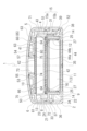
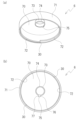
- FIG. 1A and 1B are diagrams showing a cosmetic container in a closed state according to an embodiment of the present invention, in which FIG. FIG. 2 is a cross-sectional view taken along line AA in FIG.
- FIG. 1B is a cross-sectional view taken along the line B-B of FIG.
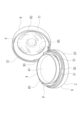
- FIG. 4 is a perspective view showing the container with the outer lid open.
- FIG. 4 is a side view showing the container with the outer lid open.
- FIG. 4 is a perspective view showing the container with the inner lid open.
- FIG. 4A and 4B are perspective views showing a main container of the container.
- FIG. 4A is a plan view of the main container
- FIG. 4B is a front view of the main container
- FIG. 4A is a perspective view showing a lower container of the container
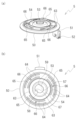
- FIG. 4A and 4B are perspective views showing a pressing member of the container.
- FIG. 4A is a plan view of the pressing member
- FIG. FIG. FIG. 4A is a perspective view showing the outer lid of the container
- FIG. FIG. FIG. 4 is a bottom view showing the outer lid and the pressing member of the container.
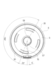
- FIG. 4 is a bottom view showing the relationship between the outer lid and the pressing member of the container.
- 5A to 5C are bottom views of the main part showing the relationship between the outer lid and the pressing member of the container.
- 5A and 5B are bottom views of essential parts showing the relationship between an outer lid and a pressing member of a cosmetic container in another embodiment of the present invention.
- FIG. 4 is a cross-sectional view showing a cosmetic container according to another embodiment of the present invention.
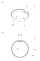
- 13A and 13B show a pressing member of a cosmetic container according to another embodiment of the present invention, where FIG.
- the cosmetic container is a container that contains cosmetics.
- the cosmetic container will be simply referred to as the container.
- Figs. 1 to 3 show the container with the lid closed.
- Figs. 4 to 6 show the container with the lid open.
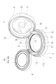
- Fig. 7 shows an exploded perspective view of the container.
- closed state or "open state” is used, it refers to the container with the lid closed and open.
- the cosmetic is, for example, a foundation.
- the foundation may be liquid or solid.
- a pad is contained in the container, and the pad is impregnated with the cosmetic.
- the container of this embodiment is circular in plan view, that is, cylindrical in shape with the center line 1 of the container in the vertical direction (axial direction).
- the shape of the container is arbitrary, and may be, for example, a polygon such as a square in plan view.
- the container comprises a container body 2 having a storage section 3 for storing a cosmetic, an inner lid 4 for sealing the storage section 3, a pressing member 5 for pressing the inner lid 4 towards the storage section 3, and an outer lid 6 for pressing the pressing member 5 towards the inner lid 4.
- the container is preferably made of a synthetic resin.
- the container body 2, the inner lid 4, the pressing member 5, and the outer lid 6 are each preferably made of a synthetic resin, and are each preferably injection molded.
- the container body 2 includes a replaceable inner container 7 for storing a cosmetic, a main container 8 for holding the inner container 7, and a lower container 9 for covering the main container 8 from below.
- the inner container 7 is the above-mentioned storage section 3.
- the inner container 7 is stored in the main container 8.
- the inner container 7 is detachable from the main container 8.
- the inner container 7 is a cylindrical container with an open top.
- the inner container 7 has an opening 10 on the top.
- the opening 10 of the inner container 7 is the opening of the container body 2.
- the inner container 7 has an inner bottom surface portion 11 (bottom surface portion), an inner side surface portion 12 (side surface portion) extending upward from the peripheral portion of the inner bottom surface portion 11, and an annular flange portion 13 extending outward from the upper end portion of the inner side surface portion 12.
- the inner bottom surface portion 11 and the inner side surface portion 12 form the storage section 3 for storing the cosmetic.
- the inner container 7 is not limited to a circular shape, and may be a polygonal shape such as a square.
- the inner container 7 may be a circular shape, and the container may be a polygonal shape such as a square.
- the inner container 7 may be a polygonal shape, and the container may be a circular shape.
- the outer peripheral surface of the inner surface portion 12 is formed with an engagement recess 14 (engagement portion) recessed radially inward.
- the engagement recess 14 is provided at one or more locations on the entire circumference of the outer peripheral surface.
- a pair of engagement recesses 14 are formed opposite each other at 180 degrees.
- the engagement recess 14 is formed at the lower part of the outer peripheral surface of the inner surface portion 12.
- the pair of engagement recesses 14 are located on line A-A in FIG. 1(b) in a plan view.
- the direction of line A-A in a plan view is referred to as the first direction in a plan view.
- the direction of line B-B in FIG. 1(b) is referred to as the second direction in a plan view.
- the second direction in a plan view is perpendicular to the first direction in a plan view.
- the pair of engagement recesses 14 are provided opposite each other in the first direction in a plan view.
- the flange portion 13 is placed on the main container 8.
- the flange portion 13 abuts against the main container 8, thereby determining the vertical position, i.e., the height, of the inner container 7.
- a knob portion 15 is provided at one point on the entire circumference of the flange portion 13.
- the knob portion 15 protrudes radially outward.
- the knob portion 15 is hook-shaped.
- the knob portion 15 has a horizontal portion 15a that extends radially outward, and an extension portion 15b that extends downward from the protruding end of the horizontal portion 15a.
- the extension portion 15b is spaced radially outward from the inner surface portion 12.
- the knob 15 is provided at a position around the entire circumference of the flange 13 that corresponds to one of the pair of engagement recesses 14.
- the position where the knob 15 is provided is the 12 o'clock position
- the position opposite the 12 o'clock position in the first direction in plan view is the 6 o'clock position.
- the positions rotated 90 degrees counterclockwise from the 12 o'clock position and the 6 o'clock position are the 9 o'clock position and the 3 o'clock position, respectively.
- the 9 o'clock position and the 3 o'clock position face each other in the second direction in plan view.
- a ring 16 is attached to the opening 10 of the inner container 7.
- the ring 16 is attached to the inner circumferential surface of the inner side surface portion 12.
- the ring 16 is located near the upper end of the inner circumferential surface of the inner side surface portion 12.
- the ring 16 is press-fitted into the inner circumferential surface of the inner side surface portion 12.
- the upper surface of the ring 16 is lower than the upper surface of the flange portion 13.
- the inner container 7 can be replaced with a new inner container 7.
- a film lid 17 is removably attached to the top surface of the flange portion 13 of the new inner container 7.
- the film lid 17 closes the opening 10 and seals the storage space of the inner container 7.
- the film lid 17 is peeled off and removed from the flange portion 13.
- the main container 8 is shown in Figures 8 and 9.
- the main container 8 is cylindrical with both the top and bottom open.
- the main container 8 does not have a bottom, but may have a bottom.
- the main container 8 has a main body side portion 20 (side portion) with both top and bottom ends open.
- the inner container 7 is accommodated radially inside the main body side portion 20.
- the main body side portion 20 is provided with a main body thread portion 21 to which the outer lid 6 is screwed, and an inner lid support portion that supports the inner lid 4.
- the main body thread portion 21 is formed with its axis being the center line 1 along the vertical direction of the container.
- the main body side portion 20 has a cylindrical main tube portion 22 that houses the inner container 7, a ring-shaped, plate-shaped mounting portion 23 that extends outwardly and approximately horizontally from the upper end of the main tube portion 22, and an outer tube portion 24 that is connected to the outer edge of the mounting portion 23.
- Both the top and bottom of the main tube portion 22 are open.
- the main tube portion 22 has a slightly larger diameter than the inner surface portion 12 of the inner container 7.
- the flange portion 13 of the inner container 7 is placed on the top surface of the mounting portion 23.
- the inner bottom surface portion 11 of the inner container 7 is located above the lower end of the main tube portion 22 or is flush with it.
- the main tube portion 22 holds the inner container 7.
- the main tube portion 22 has a pair of engaging movable pieces 25.
- a slit 26 is formed on each of the circumferential sides of the engaging movable piece 25 from the lower end of the main tube portion 22 toward the upper side, and the engaging movable piece 25 can elastically deform in the radial direction with the upper end of the engaging movable piece 25 as a fulcrum relative to other parts of the main tube portion 22.
- a pair of engaging movable pieces 25 are provided opposite each other at 180 degrees.
- the pair of engaging movable pieces 25 are provided opposite each other in the first direction when viewed from above. That is, the pair of engaging movable pieces 25 are provided at the 12 o'clock position and the 6 o'clock position.
- the engaging movable piece 25 at the 12 o'clock position is provided corresponding to the knob portion 15 of the inner container 7 and is located below the knob portion 15.
- the engaging movable piece 25 at the 6 o'clock position is provided in a position opposite the knob portion 15 of the inner container 7 in the first direction when viewed from above.
- An engagement protrusion 27 that protrudes radially inward is formed at the lower end of the inner circumferential surface of the engagement movable piece 25.
- the engagement protrusion 27 engages with the engagement recess 14 of the inner container 7. This prevents the inner container 7 from slipping out of the main container 8.
- the engagement protrusion may be provided on the inner container 7, and the engagement recess may be provided on the main container 8.
- a pressing movable piece 28 is formed on each circumferential side of the engaging movable piece 25 at the 6 o'clock position.
- the pressing movable piece 28 is spaced apart from the engaging movable piece 25 in the circumferential direction.
- the pressing movable piece 28 has a shorter circumferential length than the engaging movable piece 25.
- the width of the pressing movable piece 28 is narrower than the width of the engaging movable piece 25.
- the pressing movable piece 28 can also be elastically deformed in the radial direction with its upper end as a fulcrum.
- a pressing protrusion 29 that protrudes radially inward is formed at the lower end of the inner peripheral surface of the pressing movable piece 28.
- the pressing protrusion 29 presses the outer peripheral surface of the inner side surface portion 12 of the inner container 7 radially inward. This suppresses radial rattling of the inner container 7.
- the outer tube portion 24 extends vertically relative to the mounting portion 23.
- the outer tube portion 24 has a larger diameter than the main tube portion 22.
- the outer tube portion 24 and the main tube portion 22 are formed coaxially.
- the upper end portion of the outer tube portion 24 is located above the upper end portion of the main tube portion 22.
- the lower end portion of the outer tube portion 24 is located above the lower end portion of the main tube portion 22.
- a body thread portion 21 is formed on the outer peripheral surface of the outer tube portion 24.
- the body thread portion 21 screws into the lid thread portion 72 of the outer lid 6 described below.
- the body thread portion 21 is a male thread portion.
- the body thread portion 21 and the lid thread portion 72 are preferably multiple-thread threads.
- the body thread portion 21 may be a double-thread thread, a triple-thread thread, a four-thread thread, or the like, and the number of threads is optional.
- the body thread portion 21 is a double-thread thread.
- a single thread of the body thread portion 21 has a circumferential length of approximately 180 degrees, that is, a circumferential length of approximately half a circumference, and is arranged every 180 degrees.
- the point where the lid thread portion begins to mesh with the body thread portion 21 is referred to as the meshing start point 30.
- the meshing start point 30 In the case of a double-thread thread, there are two meshing start points 30, 180 degrees apart. In this embodiment, one meshing start point 30 is located between the 12 o'clock position and the 9 o'clock position, and the other meshing start point 30 is located between the 6 o'clock position and the 3 o'clock position.
- the threads are arranged every 120 degrees, and there are a total of three meshing start points 30 every 120 degrees.
- the threads In the case of a four-start thread, the threads are arranged every 90 degrees, and there are a total of four meshing start points 30 every 90 degrees.
- An upper recess 31 is formed at one point on the circumference of the outer tube portion 24 so as to partially cut out the outer tube portion 24.
- the upper recess 31 is recessed radially inward.
- the upper recess 31 partially cuts out the main threaded portion 21.
- the upper recess 31 reaches the mounting portion 23 and cuts out one point on the circumference of the mounting portion 23.
- the upper recess 31 is provided at the 12 o'clock position.
- the extension portion 15b of the knob portion 15 of the inner container 7 is located in the upper recess 31. In the upper recess 31, the extension portion 15b is located radially outward from the main tube portion 22 and is spaced radially outward from the main tube portion 22.
- An inner lid support shaft 32 is provided as an inner lid support part at one point on the entire circumference of the outer tube part 24.
- the inner lid support shaft 32 rotatably supports the inner lid 4.
- the inner lid support shaft 32 has a horizontal axis.
- the inner lid 4 is supported by the inner lid support shaft 32 and rotates around the horizontal axis. That is, the inner lid 4 rotates in the up-down direction.
- the inner lid support shaft 32 is formed near the upper end part of the outer tube part 24.
- the inner lid support shaft 32 is provided above the outer lid support shaft 39 described below. It is preferable that the inner lid support shaft 32 is provided above the main body screw part 21.
- the inner lid support shaft 32 In the closed state, the inner lid support shaft 32 is located radially inside the outer lid 6, and the outer lid 6 covers the inner lid support shaft 32 from the radial outside.
- the inner lid support shaft 32 is provided at the 9 o'clock position. Therefore, the inner lid support shaft 32 is spaced 90 degrees from the upper recess 31 in the circumferential direction in a plan view. Note that one of the meshing start points 30 is located between the upper recess 31 and the inner lid support shaft 32 in the circumferential direction.
- a main body flange portion 33 protrudes radially outward from the lower end of the outer tube portion 24.
- the main body flange portion 33 is formed around the entire circumference except for the upper recessed portion 31.
- An engagement ridge 34 protrudes downward from the underside of the main body flange portion 33.
- the engagement ridge 34 is formed around the entire circumference except for the upper recessed portion 31.
- the engagement ridge 34 is located radially inward from the peripheral portion of the main body flange portion 33.
- the lower container 9 is shown in Fig. 10.
- the lower container 9 covers the main container 8 from below.
- the lower container 9 closes the lower opening 10 of the main tube portion 22 of the main container 8.
- the lower container 9 is joined to the main container 8.
- the lower container 9 is preferably fixed to the main container 8 by adhesive.
- the lower container 9 has substantially the same diameter as the outer lid 6.
- the lower container 9 has a circular lower bottom surface portion 35 (bottom surface portion) and a cylindrical lower side surface portion 36 (side surface portion) extending upward from the peripheral portion of the lower bottom surface portion 35.
- the lower bottom surface portion 35 constitutes the bottom surface portion of the container body 2.
- the lower bottom surface portion 35 covers the opening on the lower surface of the main container 8.
- the lower end portion of the main tube portion 22 of the main container 8 may abut against the upper surface of the lower bottom surface portion 35, or may be spaced upward from the upper surface of the lower bottom surface portion 35.
- the inner container 7 may abut against the upper surface of the lower bottom surface portion 35, or may be spaced upward from the upper surface of the lower bottom surface portion 35.
- the lower side surface portion 36 constitutes the lower part of the side surface portion of the container body 2.
- the lower side surface portion 36 has a larger diameter than the main tube portion 22 of the main container 8 and is spaced radially outward from the main tube portion 22.
- a step portion 37 that is one step lower than the outer circumferential side is formed on the inner circumferential side of the upper end surface of the lower side surface portion 36.
- the lower surface of the main body flange portion 33 of the outer tube portion 24 of the main container 8 abuts against the step portion 37.
- the main body flange portion 33 fits into the radially inner side of the inner circumferential surface above the step portion 37, and the fitting ridge 34 of the outer tube portion 24 of the main container 8 fits into the radially inner side of the inner circumferential surface below the step portion 37.
- a lower recess 38 is formed at one point on the circumference of the lower side surface portion 36 so as to partially cut out the lower side surface portion 36.
- the lower recess 38 is recessed radially inward.
- the lower recess 38 partially cuts out the step portion 37.
- the lower recess 38 is provided at the 12 o'clock position.
- the lower recess 38 is continuous with the lower side of the upper recess 31.
- the lower recess 38 is provided with an outer lid support shaft 39 as an outer lid support part.
- the outer lid support shaft 39 rotatably supports the pressing member 5.
- the outer lid support shaft 39 has a horizontal axis.
- the pressing member 5 is supported by the outer lid support shaft 39 and rotates about the horizontal axis. In other words, the pressing member 5 rotates in the up-down direction.
- the outer lid support shaft 39 is located at the bottom of the lower recess 38.
- the lower recess 38 is located below the main body threaded portion 21.
- the outer lid support shaft 39 is located below the main body threaded portion 21.
- the outer lid support shaft 39 is circumferentially spaced 90 degrees from the inner lid support shaft 32.
- the inner lid 4 closes the opening 10 of the inner container 7.
- the inner container 7 is sealed by the inner lid 4.
- the inner lid 4 is rotatably supported by the inner lid support shaft 32.
- the inner lid 4 has an inner lid connecting part 40 which is connected to the inner lid support shaft 32 and rotatably supported by the inner lid support shaft 32.
- the inner lid 4 rotates up and down about the inner lid support shaft 32 as a fulcrum, and takes two states: a closed state of the inner lid 4 which closes the opening 10 of the inner container 7, and an open state of the inner lid 4 which opens the opening 10 of the inner container 7.
- the inner lid 4 rotates in a second direction in a plan view.
- the inner lid 4 has an accommodation recess 41 for accommodating a cosmetic tool such as a puff.
- the inner lid 4 has an inner lid bottom portion 42 and an inner lid side portion 43 extending upward from the peripheral edge of the inner lid bottom portion 42, and an accommodating recess 41 that opens upward is formed by the inner lid bottom portion 42 and the inner lid side portion 43.
- An inner lid connecting portion 40 is formed on the radially outer side of the inner lid side portion 43 so as to protrude radially outward.
- the upper end surface of the inner lid side portion 43 is the upper surface of the inner lid 4.
- the underside of the inner lid bottom portion 42 is the underside of the inner lid 4.
- a gasket 44 is attached to the underside of the inner lid bottom portion 42.
- the shape of the gasket 44 may vary, but is typically circular or ring-shaped.
- a circular inner gasket 44 and a ring-shaped outer gasket 44b are provided.
- the inner gasket 44a covers the opening 10 of the inner container 7 from above.
- the outer gasket 44b is joined to the radially outer side of the inner gasket 44a.
- the outer gasket 44b abuts against the upper surface of the flange portion 13 of the inner container 7. In this way, the inner container 7 is sealed by the gasket 44.
- the gasket 44 is configured separately from the inner lid 4, but may be formed integrally with the inner lid 4.
- the inner lid bottom portion 42 When the inner lid 4 is in the closed state, the inner lid bottom portion 42 is located radially inside the outer tube portion 24 of the main container 8. When the inner lid 4 is in the closed state, the inner lid bottom portion 42, the gasket 44, and the flange portion 13 of the inner container 7 are located below the inner lid support shaft 32. When the inner lid 4 is in the closed state, the upper end portion of the inner lid side portion 43 is located above the upper end portion of the outer tube portion 24 of the main container 8. When the outer lid 6 is in the closed state, the inner lid 4 is covered from above and from the radial outside by the outer lid 6.
- the pressing member 5 is shown in Figs. 11 to 13.
- the pressing member 5 presses the inner lid 4 from the top to the bottom when the outer lid 6 is in the closed state.
- the pressing member 5 is rotatably connected to the outer lid support shaft 39 of the container body 2.
- the pressing member 5 rotates up and down around the outer lid support shaft 39 as a fulcrum, and takes two states: a closed state in which the pressing member 5 is located above the inner lid 4, and an open state in which the pressing member 5 is separated from the inner lid 4.
- the pressing member 5 rotates in a first direction in a plan view.
- the rotation direction of the pressing member 5 is perpendicular to the rotation direction of the inner lid 4 in a plan view.
- the pressing member 5 has a circular plate portion 50, an arm portion 51 extending downward from the peripheral portion of the plate portion 50, and an outer lid connecting portion 52 (connecting portion) provided at the lower end of the arm portion 51.
- a support tube 54 having a through hole 53 penetrating vertically is formed in the center of the plate portion 50.
- the support tube 54 protrudes upward from the upper surface of the plate portion 50.
- the center line 1 of the support tube 54 is located on the center line 1 of the container in the vertical direction.
- An inward protrusion 55 that protrudes radially inward is formed on the upper end of the support tube 54.
- the inward protrusion 55 is formed around the entire circumference except for a portion.
- An insertion notch 56 is formed in the place where the inward protrusion 55 is not formed on the entire circumference of the upper end of the support tube 54.
- a restricting wall 57 is formed on the inner peripheral surface of the support tube 54.
- the restricting wall 57 is formed along the circumferential direction, and is formed on only a portion of the entire circumference of the inner peripheral surface of the support tube 54.
- One of the two circumferential end faces of the restricting wall 57 is a restricting surface 58 on the closing side, and the other is a restricting surface 59 on the opening side.
- the restricting wall 57 restricts the relative rotation of the outer lid 6 with respect to the pressing member 5 about the center line 1 of the container within a predetermined angle range.
- the restricting wall 57 By forming the restricting wall 57 over a predetermined angle range on the inner peripheral surface of the support tube 54, the entire circumference of the inner peripheral surface of the support tube 54 is divided into an unacceptable area, which is a first angle range in which the restricting wall 57 is formed, and an allowable area, which is a second angle range in which the restricting wall 57 is not formed.
- the restricting wall 57 will be described further below.
- the lower surface of the plate portion 50 has a circular mounting surface portion 60 and an annular pressing surface portion 61 formed around the mounting surface portion 60.
- the mounting surface portion 60 is located one step higher than the pressing surface portion 61.
- a plate-shaped mirror 62 having a shape and size corresponding to the mounting surface portion 60 is attached to the mounting surface portion 60.
- the mounting surface portion 60 and the mirror 62 are circular, but they may be non-circular or polygonal.
- the pressing surface portion 61 is located around the mirror 62. It is preferable that the diameter of the mirror 62 is smaller than the diameter of the upper opening 10 of the storage recess 41 of the inner lid 4.
- the pressing surface portion 61 abuts against the upper end surface of the inner lid side portion 43 of the inner lid 4.
- the pressing surface portion 61 abuts against the entire circumference of the upper end surface of the inner lid side portion 43 of the inner lid 4.
- the pressing surface portion 61 is preferably annular, but may be divided into multiple portions spaced apart in the circumferential direction.
- the upper surface of the plate portion 50 has a protruding wall 63 protruding upward.
- the protruding wall 63 is preferably annular, but may be formed at multiple locations with intervals in the circumferential direction.
- the protruding wall 63 is circular, centered on the center line 1 in the vertical direction of the container.
- the protruding wall 63 may be a single wall, but in this embodiment, two walls, an inner wall and an outer wall, are formed coaxially.
- the height of the protruding walls 63 i.e., the amount of protrusion upward, may be the same, but in this embodiment, the outer protruding wall 63 is lower than the inner protruding wall 63, corresponding to the inner surface of the outer lid 6 (the lower surface of the top surface portion 70) gradually descending from the center toward the outside in the radial direction.
- the outer protruding wall 63 is located above the pressing surface portion 61 in correspondence with it.
- the outer protruding wall 63 is located above the inner lid side portion 43 in correspondence with it.
- the plate portion 50 is formed with a hole 64 that penetrates in the vertical direction. There may be only one hole 64, but preferably there are multiple holes, and in this embodiment, a total of four holes are provided at 90 degree intervals in the circumferential direction.
- the hole 64 is provided in the mounting surface portion 60.
- the hole 64 is located between a pair of protruding walls 63.
- Each hole 64 is formed with a spring piece 65 as an elastic part.
- the spring piece 65 biases the outer lid 6 upward.
- the spring piece 65 biases the outer lid 6 in a direction away from the pressing member 5.
- the spring piece 65 extends along the circumferential direction of the body screw portion 21 and the lid screw portion 72. Since the spring piece 65 is long in the circumferential direction of the body screw portion 21 and the lid screw portion 72, the length of the spring piece 65 can be easily ensured. In a plan view, the spring piece 65 is an arc shape centered on the center line 1 of the container. The spring piece 65 elastically deforms up and down due to the elasticity of the synthetic resin that constitutes the pressing member 5. One end of the spring piece 65 in the circumferential direction is a fixed end and the other end is a free end, and the spring piece 65 elastically deforms so that the other end side bends up and down with the one end as a fulcrum.
- the other end of the spring piece 65 is the tip of the spring piece 65, and one end of the spring piece 65 is the base end of the spring piece 65.
- the spring piece 65 constantly biases the outer lid 6 in a direction away from the pressing member 5.
- the spring piece 65 presses the outer lid 6 upward.
- the other end of the spring piece 65 is a pressing part that presses the outer lid 6 upward.
- the other end of the spring piece 65 protrudes upward from the plate part 50.
- the other end of the spring piece 65 protrudes upward from the upper end surface of the pair of protruding walls 63 when the pressing member 5 is in a single state. That is, the spring piece 65 protrudes upward from the protruding wall 63 in a free state in which no load is applied.
- the spring piece 65 is inclined upward from one end to the other end.
- the spring piece 65 is curved upward.
- a pressing protrusion 66 that protrudes hemispherically upward is formed on the upper surface of the other end of the spring piece 65.
- the pressing protrusion 66 is always in point contact with the inner surface (lower surface) of the outer lid 6.
- the other end of the spring piece 65 is located in a clockwise direction from the one end in a plan view. That is, the other end of the spring piece 65 is located in the screwing direction of the outer lid 6 from the one end in a plan view.
- the arm portion 51 extends from the peripheral portion of the plate portion 50 to the outer lid support shaft 39.
- the arm portion 51 is formed at one point on the entire circumference of the peripheral portion of the plate portion 50.
- the arm portion 51 is provided at the 12 o'clock position.
- the outer lid connecting portion 52 radially clamps the outer lid support shaft 39 and is rotatably supported by the outer lid support shaft 39.
- the outer lid 6 is shown in Figure 14.
- the outer lid 6 is connected to the upper side of the pressing member 5.
- the outer lid 6 rotates vertically together with the pressing member 5, with the outer lid support shaft 39 as a fulcrum.
- the outer lid 6 is rotatable relative to the pressing member 5, with the center line 1 of the container as the center of rotation.
- the outer lid 6 is detachably screwed to the container body 2.
- the outer lid 6 covers the plate portion 50 of the pressing member 5 and the inner lid 4.
- the outer lid 6 has a top surface portion 70 and an outer lid side surface portion 71 extending downward from the peripheral edge of the top surface portion 70.
- the outer diameter of the outer lid side surface portion 71 is approximately equal to the outer diameter of the lower side surface portion 36 of the lower container 9.
- a lid thread portion 72 is formed on the inner peripheral surface of the outer lid side surface portion 71.
- the lid thread portion 72 is a female thread portion.
- the lid thread portion 72 screws into the main body thread portion 21.
- the lid thread portion 72 corresponds to the main body thread portion 21 and is a multiple start thread, which in this embodiment is a double start thread.
- the top surface 70 bulges upward.
- the top surface 70 is dome-shaped and curves gradually upward from the periphery toward the center.
- the center of the top surface 70 is located at the topmost position.
- a central support shaft 73 protrudes downward from the center of the underside of the top surface 70.
- the central support shaft 73 is located on the center line 1 of the container and has an axis in the vertical direction.
- the central support shaft 73 is hollow and tubular with an opening on the bottom side.
- the central support shaft 73 is inserted radially inside the support tube 54 of the pressing member 5.
- the inner surface of the support tube 54 rotatably supports the outer surface of the central support shaft 73.
- the outer lid 6 rotates around the vertical axis relative to the pressing member 5, with the support tube 54 as the center of rotation.
- the rotation range of the outer lid 6 is limited to less than one rotation by the above-mentioned regulating wall 57, and more specifically, is limited to a specified angle range.
- the rotation range of the outer lid 6 is limited to 1/2 rotation or more and less than one rotation.
- the rotation range is limited to 1/3 rotation or more and less than 2/3 rotation
- the rotation range is limited to 1/4 rotation or more and less than 1/2 rotation.
- An outward protrusion 74 protrudes outward from the lower end of the outer circumferential surface of the central support shaft 73.
- the inward protrusion 55 of the holding member 5 engages with the outward protrusion 74, thereby preventing the outer lid 6 from coming off the holding member 5.
- the outward protrusion 74 is preferably formed around the entire circumference.
- a stopper 75 is formed at one point on the entire circumference of the outward protrusion 74.
- the stopper 75 protrudes radially outward. The stopper 75 can be inserted through the insertion notch 56.
- the stopper 75 of the central support shaft 73 is aligned with the position of the insertion notch 56 of the support tube 54, and the central support shaft 73 is forcibly inserted into the support tube 54.
- the outward protrusions 74 of the central support shaft 73 elastically deform the inward protrusions 55 of the support tube 54 radially outward
- the inward protrusions 55 of the support tube 54 elastically deform the outward protrusions 74 of the central support shaft 73 radially inward.
- the outward protrusions 74 of the central support shaft 73 pass through the inward protrusions 55 of the support tube 54.
- the rotation of the outer lid 6 relative to the pressing member 5 is restricted within a specified angle range by the contact of both circumferential sides of the stopper 75 with the restricting wall 57.
- One circumferential side of the stopper 75 is the closing side contact surface 76, and the other side is the opening side contact surface 77.
- the closing side contact surface 76 of the stopper 75 eventually contacts the closing side restricting surface 58 of the restricting wall 57, and the outer lid 6 cannot be rotated further clockwise.
- the opening side contact surface 77 of the stopper 75 eventually contacts the opening side restricting surface 59 of the restricting wall 57, and the outer lid 6 cannot be rotated further counterclockwise.
- the stopper 75 can move circumferentially only within the allowable area of the support tube 54 of the pressing member 5.
- Figures 15 to 17 show the outer lid 6 and the pressing member 5 as viewed from the pressing member 5 side. Note that the mirror 62 is omitted from Figures 15 and 17.
- Figures 15 to 17 show the state when the outer lid 6 is screwed onto the container body 2 and the outer lid 6 is in the closed state.
- the allowable range is 215 degrees.
- the circumferential length (width) of the stopper 75 corresponds to 20 degrees. Therefore, the stopper 75 can move within an angular range of 195 degrees, which is 215 degrees minus 20 degrees.
- the outer lid 6 can rotate within an angular range of 195 degrees
- the movable range of the outer lid 6 relative to the pressing member 5 is 195 degrees.
- the stopper 75 does not abut against the regulating wall 57. That is, the contact surface 76 on the closing side of the stopper 75 does not contact the regulating surface 58 on the closing side of the regulating wall 57, and there is a space of 5 degrees between the contact surface 76 on the closing side of the stopper 75 and the regulating surface 58 on the closing side of the regulating wall 57. Therefore, the outer lid 6 can be rotated another 5 degrees in the screw-in direction, i.e., counterclockwise in FIG. 17, but the 5 degrees are a rotation margin. In the state of FIG. 17, the packing 44 is pressed and the inner container 7 is sealed.
- the outer lid 6 can be further tightened to the closing side.
- the outer lid 6 when the outer lid 6 is removed from the container body 2, the outer lid 6 can be rotated to the closing side relative to the pressing member 5 until the contact surface 76 on the closing side of the stopper 75 contacts the regulating surface 58 on the closing side of the regulating wall 57.
- FIG. 18 shows the relationship between the stopper 75 and the regulating wall 57 in more detail.
- FIG. 18 is a view from the side of the pressing member 5, as in FIG. 17. Note that the outer lid 6 is marked with many dots.
- FIG. 18(a) shows the same state as FIG. 17, with the outer lid 6 in a closed state.
- FIG. 18(b) shows the state in which the outer lid 6 has been rotated 180 degrees to the open side from the state in FIG. 18(a), with the lid screw portion 72 disengaged from the main body screw portion 21, that is, the state in which the lid screw portion 72 and the main body screw portion 21 are positioned at the engagement start point 30.
- the stopper 75 has not yet come into contact with the regulating surface 59 on the opening side of the regulating wall 57, and there is a space of 10 degrees between the abutment surface 77 on the opening side of the stopper 75 and the regulating surface 59 on the opening side of the regulating wall 57.
- the screw is a double-thread screw, so the outer lid 6 can be removed from the container body 2 by rotating the outer lid 6 180 degrees to the open side. Conversely, the outer lid 6 can be rotated 180 degrees in the closing direction from the engagement start point 30 to achieve the closed state.
- FIG. 18(c) shows the state in which the outer lid 6 has been rotated 10 degrees further in the open direction from the state in FIG. 18(b), with the opening side abutment surface 77 of the stopper 75 abutting against the opening side regulating surface 59 of the regulating wall 57. As the stopper 75 abuts against the regulating wall 57, the outer lid 6 cannot be rotated further in the open direction relative to the pressing member 5.
- the pressing member 5 is interposed between the outer lid 6 and the inner lid 4, and the outer lid 6 presses the inner lid 4 via the pressing member 5. Therefore, when the outer lid 6 is tightened, a rotational moment is not likely to act on the inner lid 4, and the inner lid 4 is not likely to twist. This prevents the sealing performance of the inner container 7 from decreasing.
- the downward pressing force of the outer lid 6 is transmitted to the plate portion 50 of the pressing member 5 via the protruding wall 63, and is transmitted to the inner lid side portion 43 of the inner lid 4 via the pressing surface portion 61.
- the pressing force of the outer lid 6 is efficiently transmitted to the packing 44 via the pressing member 5 and the inner lid 4, so that the packing 44 is reliably compressed and the opening 10 is sealed.
- the pressing force of the outer lid 6 is likely to act evenly around the entire circumference of the packing 44.
- the rotation of the outer lid 6 is restricted by the stopper 75 and the restricting wall 57. Because the rotation of the outer lid 6 is restricted within a specified angle range, unnecessary rotation of the outer lid 6 is kept to a minimum when the open outer lid 6 is screwed onto the container body 2, and the outer lid 6 can be easily closed.
- the outer lid 6 is always screwed in from the same meshing start point 30.
- a pattern 80 may be provided on the container body 2, and a pattern 81 may be provided on the outer lid 6.
- the pattern 80 on the container body 2 and the pattern 81 on the outer lid 6 may be integrated vertically to form one design. If the outer lid 6 is always screwed in from the same meshing start point 30, the pattern 81 on the outer lid 6 and the pattern 80 on the container body 2 will not be misaligned by 180 degrees in the closed state, and the circumferential position of the pattern 81 on the outer lid 6 and the circumferential position of the pattern 80 on the container body 2 will essentially match. As a result, a beautiful appearance is obtained.
- the rotation regulating section is formed by the regulating wall 57 of the support tube 54 and the stopper 75 of the central support shaft 73, the rotation regulating section is easy to configure, and the rotation range can be easily and reliably regulated.
- a stopper 75 may be provided on the support tube 54 and a restricting wall 57 may be provided on the central support shaft 73, or a rotation restricting portion may be provided on a portion other than the support tube 54 or the central support shaft 73.
- the rotation of the outer lid 6 is restricted on both the closing side and the opening side, it is also possible to restrict only the rotation on the opening side, or only the rotation on the closing side. However, it is preferable to restrict at least the rotation on the opening side.
- the spring piece 65 constantly presses against the outer lid 6. This prevents the outer lid 6 from loosening unintentionally, and the gasket 44 is kept compressed to maintain sealing force.
- the spring piece 65 also presses against the outer lid 6 not only in the closed state but also in the open state. This limits free movement of the outer lid 6 relative to the retaining member 5 in the open state. This makes it less likely that the outer lid 6 will vibrate and make a rattling noise in the open state. As unintentional vibration and noise of the outer lid 6 are suppressed, a sense of luxury can be created.
- the outer lid 6 is difficult to rotate relative to the pressing member 5 in the open state. In other words, when the outer lid 6 is removed from the container body 2, the outer lid 6 maintains almost the same circumferential orientation relative to the pressing member 5. Therefore, when closing the outer lid 6, the outer lid 6 can be screwed in immediately from the engagement start point.
- the rotation range of the outer lid 6 is restricted by the rotation restriction part, but even if a rotation restriction part is not provided, the spring piece 65 presses the outer lid 6, making it difficult for the outer lid 6 to rotate relative to the pressing member 5 in the open state. Therefore, the outer lid 6 can be screwed in from the specified engagement start point 30.
- the spring piece 65 presses the outer lid 6 upward, preventing the outer lid 6 from tilting or twisting, allowing the outer lid 6 to be screwed smoothly into the container body 2. Furthermore, even during opening and closing operations, the pressing force of the spring piece 65 acts on the outer lid 6, so the outer lid 6 can be rotated with a moderate pushing force while feeling the biasing force and repulsive force of the spring piece 65. As a result, the outer lid 6 is less likely to rattle, and a smooth rotation feel of the outer lid 6 is obtained, creating a luxurious feel. Even at the end of screwing the outer lid 6, the spring piece 65 is still pressing the outer lid 6, so the outer lid 6 can be securely fastened to the container body 2 without being overly screwed.
- the outer lid 6 can be screwed in smoothly, and the spring piece 65 can be smoothly elastically deformed downward.
- the pressing protrusion 66 on the other end of the spring piece 65 makes point contact with the outer lid 6, the sliding resistance between the outer lid 6 and the spring piece 65 is small, and the outer lid 6 can be smoothly rotated.
- the mirror 62 on the underside of the plate portion 50 covers and conceals the punched holes 64, spring pieces 65, stoppers 75, and restricting walls 57. Therefore, when the outer lid 6 is viewed from below in the open state, the spring pieces 65 and other elements provided between the outer lid 6 and the plate portion 50 of the pressing member 5 are not visible. This provides a good external appearance and creates a sense of luxury.
- the pressing surface portion 61 is provided on the radially outer side of the mirror 62, so the mirror 62 is less likely to become dirty or scratched.
- the inner lid support shaft 32 and the outer lid support shaft 39 are distributed between the main container 8 and the lower container 9, respectively, so that the inner lid support shaft 32 and the outer lid support shaft 39 can be easily installed. Also, because the inner lid support shaft 32 is located above the main body threaded portion 21 and the outer lid support shaft 39 is located below the main body threaded portion 21, the inner lid support shaft 32, the main body threaded portion 21, and the outer lid support shaft 39 can be easily formed, and the circumferential length of the main body threaded portion 21 can also be easily ensured.
- the knob 15 of the inner container 7 is located in the upper recess. Therefore, the knob 15 can be easily operated by inserting a finger into the upper recess 31, making it easy to replace the inner container 7. Because the knob 15 has an extension 15b, the knob 15 can be easily grasped when replacing the inner container 7, making the replacement even easier. Moreover, because the extension 15b is located radially inward of the arm 51 in the upper recess 31, the extension 15b can be easily stored.
- the protruding wall 63 is provided on the upper surface of the plate portion 50, but as shown in FIG. 20, the protruding wall 63 may be provided on the lower surface of the top surface portion 70 of the outer lid 6 so as to protrude downward.
- the configuration of the spring piece 65 can also be changed in various ways.
- the center of the spring piece 65 can be a pressing part that presses the outer lid 6 upward.
- the center of the spring piece 65 elastically deforms up and down with both ends as fulcrums.
- Both ends of the spring piece 65 are fixed ends.
- Both ends of the spring piece 65 are continuous with the mounting surface portion 60 of the plate portion 50 of the pressing member 5.
- the spring piece 65 is curved upward from both ends to the center.
- the center of the spring piece 65 protrudes upward from the mounting surface portion 60.
- the center of the spring piece 65 protrudes upward beyond the protruding wall 63.
- a pressing protrusion 66 is provided in the center of the spring piece 65.
- the pressing member 5 may be provided with a locking portion 67 that locks the stopper 75 in the opening side position.
- the locking portion 67 is provided, for example, on the wall surface of the through hole 53 and protrudes radially inward from the wall surface of the through hole 53.
- the stopper 75 passes over the locking portion 67 in the circumferential direction, and the stopper 75 comes into contact with or close to the restriction surface 59 on the opening side of the restriction wall 57.
- the locking portion 67 restricts the movement of the stopper 75 to the closing side.
- the stopper 75 maintains a state in which it is in contact with or close to the restriction surface 59 on the opening side of the restriction wall 57, and the rotation of the outer lid 6 to the closing side is restricted.
- the stopper 75 passes over the locking portion 67 to the closing side.
- the stopper 75 elastically deforms in the circumferential direction.
- the plate portion 50 of the pressing member 5 has a spring piece 65 formed integrally therewith as an elastic portion.
- the top surface portion 70 of the outer lid 6 may have an elastic portion such as the spring piece 65 formed integrally therewith.
- the elastic portion may be a separate structure from the pressing member 55 and the outer lid 66, and may comprise, for example, a coil spring or a leaf spring.
- the coil spring or leaf spring is preferably made of metal.
- the elastic portion is preferably provided between the top surface portion 70 of the outer lid 6 and the plate portion 50 of the pressing member 5. The elastic portion may be omitted.
- the main body threaded portion 21 and the lid threaded portion 72 were multiple threads, but they may be single threads.
- the container body 2 is provided with a replaceable inner container 7, but the storage portion 3 may be provided on the container body 2 in a non-replaceable manner. That is, the storage portion 3 may be provided integrally with the container body 2, for example, on the main container 8.
- the container body 2 is provided with two members, the main container 8 and the lower container 9, but the container body 2 may be composed of a single member.
- the inner lid support part and the outer lid support part each have a support shaft, but the inner lid connecting part 40 and the outer lid connecting part 52 may also have a support shaft.
Landscapes
- Closures For Containers (AREA)
Priority Applications (1)
| Application Number | Priority Date | Filing Date | Title |
|---|---|---|---|
| JP2024565877A JPWO2024135554A1 (https=) | 2022-12-20 | 2023-12-15 |
Applications Claiming Priority (2)
| Application Number | Priority Date | Filing Date | Title |
|---|---|---|---|
| JP2022203112 | 2022-12-20 | ||
| JP2022-203112 | 2022-12-20 |
Publications (1)
| Publication Number | Publication Date |
|---|---|
| WO2024135554A1 true WO2024135554A1 (ja) | 2024-06-27 |
Family
ID=91588838
Family Applications (1)
| Application Number | Title | Priority Date | Filing Date |
|---|---|---|---|
| PCT/JP2023/045003 Ceased WO2024135554A1 (ja) | 2022-12-20 | 2023-12-15 | 化粧料容器 |
Country Status (2)
| Country | Link |
|---|---|
| JP (1) | JPWO2024135554A1 (https=) |
| WO (1) | WO2024135554A1 (https=) |
Citations (5)
| Publication number | Priority date | Publication date | Assignee | Title |
|---|---|---|---|---|
| JPS62177415U (https=) * | 1986-04-24 | 1987-11-11 | ||
| JPH0736916U (ja) * | 1993-12-16 | 1995-07-11 | 株式会社資生堂 | 気密性コンパクト容器 |
| JP2001258636A (ja) * | 2000-03-15 | 2001-09-25 | Yoshida Industry Co Ltd | 気密容器 |
| JP2005103032A (ja) * | 2003-09-30 | 2005-04-21 | Yoshino Kogyosho Co Ltd | 化粧料容器 |
| JP2017506559A (ja) * | 2014-03-05 | 2017-03-09 | シーティーケー カンパニー リミテッドCtk Co., Ltd | パフ内蔵型化粧用パウダー容器 |
-
2023
- 2023-12-15 WO PCT/JP2023/045003 patent/WO2024135554A1/ja not_active Ceased
- 2023-12-15 JP JP2024565877A patent/JPWO2024135554A1/ja active Pending
Patent Citations (5)
| Publication number | Priority date | Publication date | Assignee | Title |
|---|---|---|---|---|
| JPS62177415U (https=) * | 1986-04-24 | 1987-11-11 | ||
| JPH0736916U (ja) * | 1993-12-16 | 1995-07-11 | 株式会社資生堂 | 気密性コンパクト容器 |
| JP2001258636A (ja) * | 2000-03-15 | 2001-09-25 | Yoshida Industry Co Ltd | 気密容器 |
| JP2005103032A (ja) * | 2003-09-30 | 2005-04-21 | Yoshino Kogyosho Co Ltd | 化粧料容器 |
| JP2017506559A (ja) * | 2014-03-05 | 2017-03-09 | シーティーケー カンパニー リミテッドCtk Co., Ltd | パフ内蔵型化粧用パウダー容器 |
Also Published As
| Publication number | Publication date |
|---|---|
| JPWO2024135554A1 (https=) | 2024-06-27 |
Similar Documents
| Publication | Publication Date | Title |
|---|---|---|
| CN110573433B (zh) | 用于容器的封闭件和具有这种封闭件的容器 | |
| CA2440400C (en) | Container lid | |
| EP1517841B1 (en) | Storage container comprising a horizontally rotatable lid | |
| JP2017154780A (ja) | キャップユニット及び飲料用容器 | |
| AU2002335934A1 (en) | Container lid | |
| KR102318725B1 (ko) | 안내형 래칭 특징부를 갖는 덮개를 포함하는 포트 | |
| CN106455793B (zh) | 具有平移固定件式盖子的化妆品盒罐 | |
| JP2017190156A (ja) | キャップユニット及び飲料用容器 | |
| CN106998882A (zh) | 包括具有倾摆挂接元件的盖子的化妆品盒罐 | |
| CN107404991A (zh) | 包括带导引固连元件的盖的化妆品罐 | |
| WO2024135554A1 (ja) | 化粧料容器 | |
| KR101804672B1 (ko) | 나사 및 힌지의 복합 개방 구조를 갖는 화장품 용기 | |
| US20250366592A1 (en) | Airtight cosmetic compact | |
| JP6295084B2 (ja) | キャップ付き容器 | |
| JP7500134B2 (ja) | パウダー容器 | |
| JP2022073071A (ja) | 二重容器 | |
| JP5607477B2 (ja) | 容器 | |
| JP7816829B1 (ja) | 飲料用容器および蓋ユニット | |
| JP2699087B2 (ja) | 容器蓋の開閉装置 | |
| KR102673009B1 (ko) | 리필 타입 화장품 용기 | |
| JP2004042947A (ja) | キャップの位置決め容器 | |
| JP7570271B2 (ja) | キャップ | |
| JP2012136268A (ja) | キャップ付き容器 | |
| JP2019196194A (ja) | 二重容器 | |
| JP2004180874A (ja) | パウダー容器 |
Legal Events
| Date | Code | Title | Description |
|---|---|---|---|
| 121 | Ep: the epo has been informed by wipo that ep was designated in this application |
Ref document number: 23906916 Country of ref document: EP Kind code of ref document: A1 |
|
| WWE | Wipo information: entry into national phase |
Ref document number: 2024565877 Country of ref document: JP |
|
| NENP | Non-entry into the national phase |
Ref country code: DE |
|
| 122 | Ep: pct application non-entry in european phase |
Ref document number: 23906916 Country of ref document: EP Kind code of ref document: A1 |