WO2024135386A1 - ロータリバルブのシール材 - Google Patents
ロータリバルブのシール材 Download PDFInfo
- Publication number
- WO2024135386A1 WO2024135386A1 PCT/JP2023/043837 JP2023043837W WO2024135386A1 WO 2024135386 A1 WO2024135386 A1 WO 2024135386A1 JP 2023043837 W JP2023043837 W JP 2023043837W WO 2024135386 A1 WO2024135386 A1 WO 2024135386A1
- Authority
- WO
- WIPO (PCT)
- Prior art keywords
- rib
- circumferential rib
- outer circumferential
- rotor
- inner circumferential
- Prior art date
- Legal status (The legal status is an assumption and is not a legal conclusion. Google has not performed a legal analysis and makes no representation as to the accuracy of the status listed.)
- Ceased
Links
Images






Classifications
-
- F—MECHANICAL ENGINEERING; LIGHTING; HEATING; WEAPONS; BLASTING
- F16—ENGINEERING ELEMENTS AND UNITS; GENERAL MEASURES FOR PRODUCING AND MAINTAINING EFFECTIVE FUNCTIONING OF MACHINES OR INSTALLATIONS; THERMAL INSULATION IN GENERAL
- F16K—VALVES; TAPS; COCKS; ACTUATING-FLOATS; DEVICES FOR VENTING OR AERATING
- F16K11/00—Multiple-way valves, e.g. mixing valves; Pipe fittings incorporating such valves
- F16K11/02—Multiple-way valves, e.g. mixing valves; Pipe fittings incorporating such valves with all movable sealing faces moving as one unit
- F16K11/08—Multiple-way valves, e.g. mixing valves; Pipe fittings incorporating such valves with all movable sealing faces moving as one unit comprising only taps or cocks
- F16K11/085—Multiple-way valves, e.g. mixing valves; Pipe fittings incorporating such valves with all movable sealing faces moving as one unit comprising only taps or cocks with cylindrical plug
-
- F—MECHANICAL ENGINEERING; LIGHTING; HEATING; WEAPONS; BLASTING
- F16—ENGINEERING ELEMENTS AND UNITS; GENERAL MEASURES FOR PRODUCING AND MAINTAINING EFFECTIVE FUNCTIONING OF MACHINES OR INSTALLATIONS; THERMAL INSULATION IN GENERAL
- F16K—VALVES; TAPS; COCKS; ACTUATING-FLOATS; DEVICES FOR VENTING OR AERATING
- F16K5/00—Plug valves; Taps or cocks comprising only cut-off apparatus having at least one of the sealing faces shaped as a more or less complete surface of a solid of revolution, the opening and closing movement being predominantly rotary
- F16K5/04—Plug valves; Taps or cocks comprising only cut-off apparatus having at least one of the sealing faces shaped as a more or less complete surface of a solid of revolution, the opening and closing movement being predominantly rotary with plugs having cylindrical surfaces; Packings therefor
- F16K5/0457—Packings
- F16K5/0471—Packings between housing and plug
Definitions
- This disclosure relates to a sealing material for a rotary valve.
- a sealing member provided in a valve that controls a flow path through which a fluid flows is disclosed (for example, Patent Document 1 and Patent Document 2).
- the valve disclosed in Patent Document 1 (a flow path switching valve in Patent Document 1) comprises a valve body in which a valve chamber is formed, a sealing member housed in the valve chamber, a rotating part having a valve body housed in the valve chamber and in which a circular valve opening is formed, and a valve drive part which is a drive source for rotating the rotating part.
- the sealing member is disposed on the outside of the valve body in the valve radial direction, and is formed to surround the valve body in an annular shape.
- the valve disclosed in Patent Document 2 (called a rotary slide valve in Patent Document 2) comprises a housing, a rotating slide, and a sealing element disposed between the rotating slide and the housing, the sealing element comprising a first ridge and a second ridge extending in a first radial direction, and a third ridge extending in a second radial direction.
- the sealing member disclosed in Patent Document 1 has multiple annular sealing parts that surround the periphery of the valve opening, and there is a risk that the surface pressure received by the sealing parts increases when the valve body rotates, resulting in increased sliding resistance. Also, in the sealing element disclosed in Patent Document 2, if the slope of the third raised part extending in the second radial direction is steep, there is a risk that the surface pressure received by the sealing element increases when the rotating slide rotates, resulting in increased sliding resistance.
- This disclosure was made in consideration of the above problems, and its purpose is to provide a sealing material for rotary valves that can reduce sliding resistance.
- the rotary valve sealant according to the present disclosure is characterized in that it is disposed between a rotor and a housing that accommodates the rotor, and includes a main body extending along the circumferential direction of the rotor and the axial direction of the rotor, and a rib protruding from the main body in the radial direction of the rotor, the rib having a circumferential rib extending along the circumferential direction, the circumferential rib including an inner circumferential rib protruding inward in the radial direction and an outer circumferential rib protruding outward in the radial direction, the number of the inner circumferential ribs being less than the number of the outer circumferential ribs, and the inclination of the inner circumferential rib inclined portion between the inner circumferential rib base end and the inner circumferential rib apex of the inner circumferential rib being gentler than the inclination of the outer circumferential rib inclined portion between the outer circumfer
- the number of inner circumferential ribs that slide against the rotor is fewer than the number of outer circumferential ribs, so the sliding resistance of the rotor can be reduced. Also, because there are fewer inner circumferential ribs that slide against the rotor compared to the outer circumferential ribs that slide against the housing, the frictional resistance between the housing and the sealant increases, and it is possible to prevent the sealant from shifting position as the rotor rotates. Also, with this configuration, the inner circumferential rib inclined portion is more gently inclined than the outer circumferential rib inclined portion, so that the inner circumferential ribs are prevented from collapsing due to the rotation of the rotor, and the durability of the sealant can be increased. Also, because the outer circumferential rib inclined portion is more steeply inclined than the inner circumferential rib inclined portion, the reaction force of the sealant against the rotor can be reduced.
- FIG. 1 is a vertical cross-sectional view showing a configuration of a rotary valve according to an embodiment.
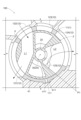
- FIG. 4 is a diagram illustrating a first position of the rotor according to the embodiment.
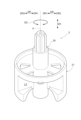
- FIG. 2 is a perspective view showing a rotor according to the embodiment.
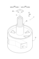
- FIG. 4 is a perspective view showing the rotor as viewed from an angle different from that shown in FIG. 3 .
- FIG. 2 is a perspective view showing a sealing material according to an embodiment.
- FIG. 6 is a perspective view showing the sealing material as viewed from an angle different from that in FIG. 5 .
- 5A and 5B are diagrams illustrating a configuration of a circumferential rib according to the embodiment.
- FIGS. 5A and 5B are diagrams illustrating a configuration of an axial rib according to the embodiment.
- FIG. 4 is a schematic diagram showing the positional relationship of apexes of a rib according to the embodiment.
- FIG. 11 is a diagram illustrating a second position of the rotor according to the embodiment.
- FIG. 13 is a diagram illustrating a third position of the rotor according to the embodiment.
- FIG. 13 is a diagram illustrating a fourth position of the rotor according to the embodiment.
- [Basic configuration] 1 shows a cross section (longitudinal cross section) along an axis X of a rotary valve 100.
- the rotary valve 100 is a five-way valve, and is used to control a fluid flowing to a device to be cooled, such as a battery or a motor mounted on a vehicle such as an automobile.
- the fluid is a cooling water such as a long-life coolant (LLC).
- LLC long-life coolant
- the fluid may also be a paraffin-based insulating oil, a hydrofluorocarbon (HFC), a hydrofluoroolefin (HFO), or other refrigerant.
- the rotary valve 100 includes a housing 1, a rotor 2 accommodated in the housing 1, a bush 3 that rotatably supports the rotor 2, a seal material 4 disposed between the housing 1 and the rotor 2, and an actuator 5 connected to the rotor 2.
- the actuator 5 transmits a rotational force to the rotor 2.
- the rotor 2 rotates about the axis X due to the rotational force from the actuator 5.
- the flow of the fluid is controlled by the rotation of the rotor 2.
- the direction along the axis X of the rotor 2 will be referred to as the "axial direction DX”
- the circumferential direction DC of the rotor 2 will be referred to simply as the “circumferential direction DC”
- the radial direction DR of the rotor 2 will be referred to simply as the “radial direction DR”.
- the direction from the outside to the inside of the radial direction DR will be referred to as the “radial inward direction DR1”
- the opposite direction will be referred to as the "radial outward direction DR2”.
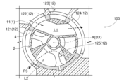
- Fig. 2 is a cross-sectional view showing the rotary valve 100.
- Fig. 2 is a view of the rotary valve 100 seen from the actuator 5 side.
- the housing 1 has a housing wall portion 11 that defines a space in which the rotor 2 is housed.
- the housing wall 11 has a circular shape when viewed along the axial direction DX.
- a plurality of ports 12 are formed in the housing wall 11 along the circumferential direction DC.
- four ports 12 are formed in the housing wall 11 along the circumferential direction DC, and the four ports 12 penetrate the housing wall 11 along the radial direction DR.
- the four ports 12 are referred to as the "first port 121,” the “second port 122,” the “third port 123,” and the "fourth port 124,” respectively.
- a fifth port 125 is formed in the lower portion (bottom wall) of the housing wall portion 11.
- Each of the first port 121, the second port 122, the third port 123, the fourth port 124, and the fifth port 125 is connected to a different external flow path.
- the external flow path is connected to, for example, a battery, a motor, etc.
- FIG. 3 and 4 are perspective views showing the rotor 2.
- the rotor 2 includes a shaft portion 20 coaxial with the axis X, and a cylindrical valve portion 21 that can rotate integrally with the shaft portion 20.
- the rotor 2 is made of a material such as resin, and the shaft portion 20 and the valve portion 21 are integrally formed.
- the valve section 21 is formed with a first valve flow path L1 and a second valve flow path L2 through which fluid flows when the rotor 2 is in a predetermined position.
- the first valve flow path L1 is formed in a substantially V-shape that bends near the axis X when viewed in the axial direction DX (see Figure 2).
- the second valve flow path L2 is formed by a section cut out in a sector shape (a truncated cone shape in three dimensions) centered on the axis X (see Figure 3).
- the seal material 4 is disposed between the housing 1 and the rotor 2 over substantially the entire circumference in the circumferential direction DC of the rotor 2.
- the seal material 4 is made of an elastically deformable member, and is compressed by the housing 1 and the rotor 2 to prevent fluid from flowing into other flow paths.
- the seal material 4 is made of rubber such as nitrile rubber (NBR), fluororubber (FKM), or urethane rubber (U).
- the seal material 4 has a cylindrical seal main body 41 (an example of a main body). Note that in Figures 5 and 6, a portion of the seal material 4 in the circumferential direction DC is cut away.
- the seal body 41 when the sealing material 4 is disposed between the housing 1 and the rotor 2, the seal body 41 extends along the circumferential direction DC and the axial direction DX.
- the seal body 41 includes a protrusion 411 (an example of a rotation prevention portion) that prevents the sealing material 4 from rotating relative to the housing 1.
- the protrusion 411 protrudes outward in the radial direction DR from both ends of the seal body 41 in the circumferential direction DC and is accommodated in a recess 111 in the housing wall 11.
- the protrusion 411 faces (contacts) the housing wall 11 of the housing 1 in the circumferential direction DC, preventing the sealing material 4 from rotating relative to the housing 1.
- the seal body 41 is formed with a seal opening 41h (one example of an opening) that penetrates the seal body 41 and through which a fluid passes.
- the seal body 41 is formed with four seal openings 41h along the circumferential direction DC, and the four seal openings 41h are formed at positions corresponding to the four ports 12 of the housing 1 described with reference to FIG. 2.
- the four seal openings 41h are referred to as the "first seal opening h1,” the "second seal opening h2," the “third seal opening h3,” and the "fourth seal opening h4,” respectively.
- the dimensions of the first seal opening h1 and the fourth seal opening h4 in the circumferential direction DC are formed to be larger than the dimensions of the second seal opening h2 and the third seal opening h3 in the circumferential direction DC.
- This allows fluids flowing in from different ports 12 (e.g., the second port 122 and the third port 123) to flow out to the same port 12 (e.g., the first port 121) (see Figures 2 and 10).
- fluids flowing in from the same port 12 e.g., the third port 123 can flow into a different port 12 (e.g., the first port 121 or the fourth port 124) (see Figures 10 and 12).
- the seal material 4 includes a rib 42 that protrudes from the seal body 41 in the radial direction DR.
- the rib 42 has a circumferential rib 43 that extends (is provided continuously) along the circumferential direction DC.
- the circumferential rib 43 includes an inner circumferential rib 44 that is provided in the radially inward direction DR1 of the seal body 41 and protrudes in the radially inward direction DR1, and an outer circumferential rib 45 that is provided in the radially outward direction DR2 of the seal body 41 and protrudes in the radially outward direction DR2.
- the number of the inner circumferential ribs 44 is smaller than the number of the outer circumferential ribs 45, and in this embodiment, two inner circumferential ribs 44 and four outer circumferential ribs 45 are provided on the seal body 41.
- the circumferential rib 43 is composed of two rib groups 43g provided at both ends of the seal body 41 in the axial direction DX.
- the rib groups 43g are provided to sandwich the four seal openings 41h in the axial direction DX.
- the rib group 43g includes two outer circumferential ribs 45 and one inner circumferential rib 44 provided between the two outer circumferential ribs 45.
- the outer circumferential rib 45 located on the end side of the seal body 41 in the axial direction DX is referred to as the "first outer circumferential rib 45a”
- the outer circumferential rib 45 located on the center side of the seal body 41 in the axial direction DX is referred to as the "second outer circumferential rib 45b”.
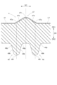
- FIG. 7 is a schematic cross-sectional view of the sealing material 4 cut along the axial direction DX.
- a sliding property improving layer LY that improves sliding property is provided on the surface of the inner circumferential rib 44.
- the sliding property improving layer LY is formed by applying a material having a smaller friction coefficient than that of the outer circumferential rib 45 (the material of the rib 42).
- the sliding property improving layer LY is made of polyacetal (POM), polyamide (PA), polytetrafluoroethylene (PTFE), etc.
- the inclination of the inner circumferential rib inclined portion 44k of the inner circumferential rib 44 is gentler than the inclination of the outer circumferential rib inclined portion 45k of the outer circumferential rib 45.
- the vicinity of the inner circumferential rib apex 44t and the vicinity of the outer circumferential rib apex 45t have an arc shape in cross section, and the radius of curvature of the arc constituting the vicinity of the inner circumferential rib apex 44t is larger than the radius of curvature of the arc constituting the vicinity of the outer circumferential rib apex 45t.
- the inner circumferential rib inclined portion 44k is the portion between the inner circumferential rib base end 44p, which is the base end of the inner circumferential rib 44, and the inner circumferential rib apex 44t, which is the apex of the inner circumferential rib 44
- the outer circumferential rib inclined portion 45k is the portion between the outer circumferential rib base end 45p, which is the base end of the outer circumferential rib 45, and the outer circumferential rib apex 45t, which is the apex of the outer circumferential rib 45.
- the rib 42 further includes an axial rib 46 extending (continuously provided) along the axial direction DX.
- the axial rib 46 includes an inner axial rib 47 provided in the radially inward direction DR1 of the seal body 41 and protruding in the radially inward direction DR1, and an outer axial rib 48 provided in the radially outward direction DR2 of the seal body 41 and protruding in the radially outward direction DR2.
- the inner circumferential rib 44 and the inner axial rib 47 may be collectively referred to as the "inner rib”
- the outer circumferential rib 45 and the outer axial rib 48 may be collectively referred to as the "outer rib”.
- FIG. 8 is a schematic cross-sectional view of a portion of the sealing material 4 cut along a direction perpendicular to the axial direction DX.
- the inner axial rib 47 also has a sliding property improving layer LY on its surface. That is, the inner rib has a sliding property improving layer LY on its surface.
- the shape of the axial rib 46 is also substantially the same as the shape of the circumferential rib 43. More specifically, the inclination of the inner axial rib inclined portion 47k of the inner axial rib 47 is gentler than the inclination of the outer axial rib inclined portion 48k of the outer axial rib 48.
- the inner axial rib inclined portion 47k is the portion between the inner axial rib base end 47p, which is the base end of the inner axial rib 47, and the inner axial rib apex 47t, which is the apex of the inner axial rib 47
- the outer axial rib inclined portion 48k is the portion between the outer axial rib base end 48p, which is the base end of the outer axial rib 48, and the outer axial rib apex 48t, which is the apex of the outer axial rib 48.
- the inner axial rib 47 and the outer axial rib 48 are arranged to sandwich each of the four seal openings 41h in the circumferential direction DC.
- the ribs 42 (the circumferential rib 43 and the axial rib 46) are arranged to surround the seal openings 41h.
- the inner axial rib 47 has an end in the axial direction DX connected to the inner circumferential rib 44
- the outer axial rib 48 has an end in the axial direction DX connected to the second outer circumferential rib 45b.
- first connection portion C1 between the inner axial rib 47 and the inner circumferential rib 44 and the second connection portion C2 between the outer axial rib 48 and the second outer circumferential rib 45b have a rounded R shape when viewed along the radial direction DR.
- FIG. 9 is a schematic diagram showing the positional relationship of the apexes of the ribs 42.
- the inner circumferential rib 44 and the outer circumferential rib 45 are provided so that the inner circumferential rib apex 44t and the outer circumferential rib apex 45t do not overlap when viewed along the radial direction DR.
- the inner circumferential rib apex 44t is provided between two (adjacent) outer circumferential rib apexes 45t in the axial direction DX.
- the inner axial rib 47 and the outer axial rib 48 are provided so that the inner axial rib apex 47t and the outer axial rib apex 48t do not overlap when viewed along the radial direction DR.
- the inner axial rib apex 47t is provided between the outer axial rib apexes 48t of the two (adjacent) outer axial ribs 48 in the circumferential direction DC.
- Fig. 2 shows the rotary valve 100 with the rotor 2 set to a first position P1
- Fig. 10 shows the rotary valve 100 with the rotor 2 set to a second position P2
- Fig. 11 shows the rotary valve 100 with the rotor 2 set to a third position P3
- Fig. 12 shows the rotary valve 100 with the rotor 2 set to a fourth position P4.
- the fluid supplied to the third port 123 passes through the first valve flow path L1 and is supplied to the first port 121.
- the fluid supplied to the fifth port 125 passes through the second valve flow path L2 and flows to the fourth port 124.
- the sliding resistance can be reduced because the number of the inner circumferential ribs 44 in sliding contact with the rotor 2 is smaller than the number of the outer circumferential ribs 45.
- the frictional resistance between the housing 1 and the seal material 4 becomes large, and it is possible to prevent the seal material 4 from shifting in position as the rotor 2 rotates.
- the circumferential rib 43 is composed of two rib groups 43g at both ends in the axial direction DX, the forces acting on the sealing material 4 can be balanced, and deformation (falling) of the sealing material 4 can be suppressed.
- the rib group 43g includes two outer circumferential ribs 45 and one inner circumferential rib 44 provided between the two outer circumferential ribs 45, when a force (force from the rotor 2) acts on the inner circumferential rib 44, the space between the two outer circumferential ribs 45 can be deflected. As a result, the reaction force of the sealing material 4 against the rotor 2 can be reduced, and sliding resistance can be reduced.
- the inner circumferential rib 44 and the outer circumferential rib 45 are arranged so that the inner circumferential rib apex 44t of the inner circumferential rib 44 and the outer circumferential rib apex 45t of the outer circumferential rib 45 do not overlap when viewed along the radial direction DR. This allows the sealing material 4 to bend outward when a force (force from the rotor 2) acts on the inner circumferential rib 44, thereby reducing the reaction force of the sealing material 4 on the rotor 2.
- the inner circumferential rib inclined portion 44k is more gently inclined than the outer circumferential rib inclined portion 45k, the inner circumferential rib 44 is prevented from collapsing due to the rotation of the rotor 2, and the durability of the sealing material 4 can be improved.
- the outer circumferential rib inclined portion 45k is more steeply inclined than the inner circumferential rib inclined portion 44k, the reaction force of the sealing material 4 against the rotor 2 can be reduced.
- the axial ribs 46 extending along the axial direction DX are connected to the circumferential ribs 43 extending along the circumferential direction DC, and the circumferential ribs 43 and the axial ribs 46 surround the seal opening 41h through which the fluid flows in and out, thereby further improving the sealing performance of the seal material 4.
- connection portions (first connection portion C1 and second connection portion C2) between the axial rib 46 and the circumferential rib 43 are R-shaped, it is possible to prevent the inner circumferential rib apex 44t of the inner circumferential rib 44 and the outer circumferential rib apex 45t of the outer circumferential rib 45 from overlapping in the radial direction DR throughout the entire seal body 41. This allows the outer circumferential rib apex 45t to flex throughout the entire seal body 41, reducing the reaction force of the seal material 4 on the rotor 2.
- the inner circumferential rib 44 has a sliding property improving layer LY on its surface, which is made of a material having a smaller friction coefficient than the outer circumferential rib 45, thereby further reducing the sliding resistance of the rotor 2.
- the seal body 41 includes a protrusion 411 that protrudes in the radially outward direction DR2, and the protrusion 411 faces the housing wall 11 of the housing 1 in the circumferential direction DC, so that rotation of the seal material 4 relative to the housing 1 (rotation together with the rotor 2 and misalignment) can be prevented.
- the outer circumferential rib 45 which has a greater distance (radius) from the center of rotation of the rotor 2 than the inner circumferential rib 44, the torque required to rotate the outer circumferential rib 45 becomes greater than the torque required to rotate the inner circumferential rib 44, and rotation of the seal material 4 relative to the housing 1 can be suppressed.
- the rib group 43g is described as being composed of one inner circumferential rib 44 and two outer circumferential ribs 45.
- the number of inner circumferential ribs 44 is less than the number of outer circumferential ribs 45
- the number of inner circumferential ribs 44 and outer circumferential ribs 45 constituting the rib group 43g is not limited to the above.
- the rib group 43g may be composed of two inner circumferential ribs 44 and three outer circumferential ribs 45.
- At least some of the inner axial rib apexes 47t and at least some of the outer axial rib apexes 48t may overlap when viewed in the radial direction DR.
- at least some of the apexes of the inner ribs may overlap with at least some of the apexes of the outer ribs when viewed along the radial direction DR.
- first connection portion C1 and the second connection portion C2 are R-shaped. However, at least one of the first connection portion C1 and the second connection portion C2 does not have to be R-shaped.
- the inner circumferential rib 44 and the inner axial rib 47 may omit the sliding property improving layer LY.
- the seal body 41 includes a protrusion 411 that prevents rotation of the seal material 4 relative to the housing 1.
- the seal body 41 may also prevent rotation of the seal material 4 relative to the housing 1 by a configuration other than the protrusion 411 (for example, a protrusion that protrudes along the axial direction DX engages with the housing 1).
- the rotary valve 100 is described as a five-way valve, but the rotary valve 100 may be a three-way valve, a four-way valve, or the like.
- the number of ports 12 formed in the housing 1 is not limited to five, and may be changed as appropriate depending on the number of fluid directions controlled by the rotary valve 100.
- the fluid inlet and outlet are not limited to those described in this embodiment and can be interchanged. In other words, the direction of fluid flow may be reversed.
- the feature of the seal material 4 of the rotary valve 100 according to the present disclosure is that the seal material 4 of the rotary valve 100 is disposed between the rotor 2 and the housing 1 that accommodates the rotor 2, and includes a seal body portion 41 (main body portion) that extends along the circumferential direction DC of the rotor 2 and the axial direction DX of the rotor 2, and a rib 42 that protrudes from the seal body portion 41 (main body portion) in the radial direction DR of the rotor 2, and the rib 42 has a circumferential rib 43 that extends along the circumferential direction DC, and the circumferential rib
- the rib 43 includes an inner circumferential rib 44 that protrudes inward in the radial direction DR and an outer circumferential rib 45 that protrudes outward in the radial direction DR, and the number of the inner circumferential ribs 44 is less than the number of the outer circumferential ribs 45, and the inclination of the inner circumferential
- the number of inner circumferential ribs 44 that slide against the rotor 2 is smaller than the number of outer circumferential ribs 45, so the sliding resistance of the rotor 2 can be reduced. Also, since the number of inner circumferential ribs 44 that slide against the rotor 2 is smaller than the number of outer circumferential ribs 45 that slide against the housing 1, the frictional resistance between the housing 1 and the seal material 4 increases, and the seal material 4 can be prevented from shifting position as the rotor 2 rotates.
- the inner circumferential rib inclined portion 44k is more gently inclined than the outer circumferential rib inclined portion 45k, so that the inner circumferential rib 44 is prevented from falling due to the rotation of the rotor 2, and the durability of the seal material 4 can be improved. Also, since the outer circumferential rib inclined portion 45k is more steeply inclined than the inner circumferential rib inclined portion 44k, the reaction force of the seal material 4 against the rotor 2 can be reduced.
- the circumferential rib 43 is composed of two rib groups 43g provided at both ends in the axial direction DX, and the rib group 43g may include two outer circumferential ribs 45 and one inner circumferential rib 44 between the two outer circumferential ribs 45.
- the circumferential rib 43 is composed of two rib groups 43g at both ends in the axial direction DX, so that the forces acting on the sealing material 4 can be balanced and deformation (falling) of the sealing material 4 can be suppressed.
- the rib group 43g includes two outer circumferential ribs 45 and one inner circumferential rib 44 provided between the two outer circumferential ribs 45, when a force acts on the inner circumferential rib 44, the space between the two outer circumferential ribs 45 can be deflected. As a result, the reaction force of the sealing material 4 against the rotor 2 can be reduced, and sliding resistance can be reduced.
- the inner circumferential rib 44 and the outer circumferential rib 45 may be arranged such that the inner circumferential rib apex 44t of the inner circumferential rib 44 and the outer circumferential rib apex 45t of the outer circumferential rib 45 do not overlap when viewed along the radial direction DR.
- the inner circumferential rib apex 44t and the outer circumferential rib apex 45t do not overlap, so when a force acts on the inner circumferential rib 44, the sealing material 4 can bend outward, reducing the reaction force of the sealing material 4 on the rotor 2.
- the inner circumferential rib apex 44t may be located between adjacent outer circumferential rib apexes 45t.
- the inner circumferential rib apex 44t is located between the adjacent outer circumferential rib apex 45t, so that when a force acts on the inner circumferential rib 44, the sealing material 4 can bend outward, thereby reducing the reaction force of the sealing material 4 on the rotor 2.
- the rib 42 may further have an axial rib 46 extending along the axial direction DX and connected to the circumferential rib 43, and the circumferential rib 43 and the axial rib 46 may surround a seal opening 41h (opening) formed in the seal main body 41 (main body) through which a fluid passes.
- the axial rib 46 extending along the axial direction DX is connected to the circumferential rib 43 extending along the circumferential direction DC, and the circumferential rib 43 and the axial rib 46 surround the seal opening 41h (opening) through which the fluid flows in and out, thereby further improving the sealing performance.
- connection portion C1 and the second connection portion C2 (connection portion) between the axial rib 46 and the circumferential rib 43 may be R-shaped.
- connection portion C1 and the second connection portion C2 connection portion between the axial rib 46 and the circumferential rib 43 are R-shaped, so that the inner circumferential rib apex 44t of the inner circumferential rib 44 and the outer circumferential rib apex 45t of the outer circumferential rib 45 can be prevented from overlapping in the radial direction DR throughout the entire seal body 41 (body). This makes it possible to reduce the reaction force of the seal material 4 on the rotor 2.
- the inner circumferential rib 44 may be provided on its surface with a sliding property improving layer LY made of a material having a friction coefficient smaller than that of the outer circumferential rib 45.
- the inner circumferential rib 44 has a sliding property improving layer LY on its surface, which is made of a material having a friction coefficient smaller than that of the outer circumferential rib 45, and therefore the sliding resistance of the rotor 2 can be further reduced.
- the seal body 41 may include a protrusion 411 (rotation prevention portion) that protrudes outward in the radial direction DR so as to face the housing wall 11 (wall portion) of the housing 1 in the circumferential direction DC.
- the seal body 41 (body) includes a protrusion 411 (rotation prevention portion) that protrudes outward in the radial direction DR, and the protrusion 411 (rotation prevention portion) faces the housing wall 11 (wall portion) of the housing 1 in the circumferential direction DC, preventing rotation (misalignment) of the seal material 4 relative to the housing 1.
- This disclosure can be used as a sealing material for rotary valves.
- 1 housing, 2: rotor, 11: housing wall (wall), 4: seal material, 41: seal body (body), 41h: seal opening (opening), 42: rib, 43: circumferential rib, 43g: rib group, 44: inner circumferential rib, 44k: inner circumferential rib inclined portion, 44p: inner circumferential rib base end, 44t: inner circumferential rib apex, 45: outer circumferential rib, 45k: outer circumferential rib inclined portion, 45p: outer circumferential rib base end, 45t: outer circumferential rib apex, 46: axial rib, 100: rotary valve, 411: protrusion (rotation prevention portion), C1: first connection portion (connection portion), C2: second connection portion (connection portion), DC: circumferential direction, DR: radial direction, DX: axial direction, LY: sliding property improving layer, X: axial center
Landscapes
- Engineering & Computer Science (AREA)
- General Engineering & Computer Science (AREA)
- Mechanical Engineering (AREA)
- Sealing Devices (AREA)
- Taps Or Cocks (AREA)
Priority Applications (3)
| Application Number | Priority Date | Filing Date | Title |
|---|---|---|---|
| CN202380088254.0A CN120390857A (zh) | 2022-12-20 | 2023-12-07 | 旋转阀的密封件 |
| JP2024565791A JPWO2024135386A1 (https=) | 2022-12-20 | 2023-12-07 | |
| EP23906752.3A EP4641056A4 (en) | 2022-12-20 | 2023-12-07 | Sealing material for rotary pump |
Applications Claiming Priority (2)
| Application Number | Priority Date | Filing Date | Title |
|---|---|---|---|
| JP2022203580 | 2022-12-20 | ||
| JP2022-203580 | 2022-12-20 |
Publications (1)
| Publication Number | Publication Date |
|---|---|
| WO2024135386A1 true WO2024135386A1 (ja) | 2024-06-27 |
Family
ID=91588355
Family Applications (1)
| Application Number | Title | Priority Date | Filing Date |
|---|---|---|---|
| PCT/JP2023/043837 Ceased WO2024135386A1 (ja) | 2022-12-20 | 2023-12-07 | ロータリバルブのシール材 |
Country Status (4)
| Country | Link |
|---|---|
| EP (1) | EP4641056A4 (https=) |
| JP (1) | JPWO2024135386A1 (https=) |
| CN (1) | CN120390857A (https=) |
| WO (1) | WO2024135386A1 (https=) |
Cited By (1)
| Publication number | Priority date | Publication date | Assignee | Title |
|---|---|---|---|---|
| WO2026023381A1 (ja) * | 2024-07-24 | 2026-01-29 | Nok株式会社 | シール部材 |
Citations (6)
| Publication number | Priority date | Publication date | Assignee | Title |
|---|---|---|---|---|
| JPH0643433U (ja) * | 1992-11-17 | 1994-06-10 | 象印マホービン株式会社 | 水路切換弁 |
| JPH10213248A (ja) * | 1997-01-30 | 1998-08-11 | Osaka Gas Co Ltd | バルブ |
| JP2015034560A (ja) * | 2013-08-07 | 2015-02-19 | 株式会社不二工機 | シール部材及びそれを用いた流路切換弁 |
| JP2017207157A (ja) | 2016-05-19 | 2017-11-24 | 株式会社デンソー | 流路切替弁 |
| JP2019163836A (ja) * | 2018-03-20 | 2019-09-26 | 株式会社ケーヒン | 流体制御バルブ |
| DE102022200540A1 (de) | 2022-01-18 | 2023-07-20 | Volkswagen Aktiengesellschaft | Drehschieberventil für ein Thermomanagementsystem eines Kraftfahrzeugs |
Family Cites Families (2)
| Publication number | Priority date | Publication date | Assignee | Title |
|---|---|---|---|---|
| CN115218001B (zh) * | 2021-04-16 | 2025-11-11 | 浙江三花汽车零部件有限公司 | 控制阀 |
| CN115325212B (zh) * | 2022-08-01 | 2025-03-11 | 东风富士汤姆森调温器有限公司 | 一种车用热管理系统六通水阀 |
-
2023
- 2023-12-07 WO PCT/JP2023/043837 patent/WO2024135386A1/ja not_active Ceased
- 2023-12-07 JP JP2024565791A patent/JPWO2024135386A1/ja active Pending
- 2023-12-07 EP EP23906752.3A patent/EP4641056A4/en active Pending
- 2023-12-07 CN CN202380088254.0A patent/CN120390857A/zh active Pending
Patent Citations (6)
| Publication number | Priority date | Publication date | Assignee | Title |
|---|---|---|---|---|
| JPH0643433U (ja) * | 1992-11-17 | 1994-06-10 | 象印マホービン株式会社 | 水路切換弁 |
| JPH10213248A (ja) * | 1997-01-30 | 1998-08-11 | Osaka Gas Co Ltd | バルブ |
| JP2015034560A (ja) * | 2013-08-07 | 2015-02-19 | 株式会社不二工機 | シール部材及びそれを用いた流路切換弁 |
| JP2017207157A (ja) | 2016-05-19 | 2017-11-24 | 株式会社デンソー | 流路切替弁 |
| JP2019163836A (ja) * | 2018-03-20 | 2019-09-26 | 株式会社ケーヒン | 流体制御バルブ |
| DE102022200540A1 (de) | 2022-01-18 | 2023-07-20 | Volkswagen Aktiengesellschaft | Drehschieberventil für ein Thermomanagementsystem eines Kraftfahrzeugs |
Non-Patent Citations (1)
| Title |
|---|
| See also references of EP4641056A1 |
Cited By (1)
| Publication number | Priority date | Publication date | Assignee | Title |
|---|---|---|---|---|
| WO2026023381A1 (ja) * | 2024-07-24 | 2026-01-29 | Nok株式会社 | シール部材 |
Also Published As
| Publication number | Publication date |
|---|---|
| JPWO2024135386A1 (https=) | 2024-06-27 |
| EP4641056A4 (en) | 2026-04-22 |
| EP4641056A1 (en) | 2025-10-29 |
| CN120390857A (zh) | 2025-07-29 |
Similar Documents
| Publication | Publication Date | Title |
|---|---|---|
| JP7543445B2 (ja) | プラグバルブの密封用可変シリンダー壁 | |
| JP2024525305A (ja) | ロータリーディスクバルブ | |
| KR102522246B1 (ko) | 편심형 버터플라이 밸브 | |
| CN112664679B (zh) | 阀装置 | |
| WO2011039918A1 (ja) | ロータリー弁 | |
| JP2013044415A (ja) | 流路切換弁 | |
| CN115380182A (zh) | 筒形壁上的旋塞阀硬密封件 | |
| KR20230091054A (ko) | 로터리 디스크 밸브 | |
| WO2024135386A1 (ja) | ロータリバルブのシール材 | |
| JP2011174570A (ja) | 密封装置 | |
| JP7148449B2 (ja) | 三方弁 | |
| JP2019019975A (ja) | 二重偏心弁 | |
| US11619310B2 (en) | Double eccentric valve | |
| JP7152341B2 (ja) | 回転式切換弁 | |
| CN119914708A (zh) | 旋转阀 | |
| JP7360747B2 (ja) | 軸シール部材及びシール構造 | |
| TWI902983B (zh) | 流量控制用三通閥及溫度控制裝置 | |
| JP2008309223A (ja) | トリポード型等速自在継手用ブーツ | |
| CN111542714B (zh) | 蝶形阀 | |
| JP2018080724A (ja) | 制御弁 | |
| JP7365535B1 (ja) | 弁装置 | |
| JP7413615B1 (ja) | 弁装置 | |
| JP7548596B2 (ja) | ロータリバルブ | |
| JP2025119262A (ja) | バルブ制御装置 | |
| JP7724012B2 (ja) | ロータリバルブ |
Legal Events
| Date | Code | Title | Description |
|---|---|---|---|
| 121 | Ep: the epo has been informed by wipo that ep was designated in this application |
Ref document number: 23906752 Country of ref document: EP Kind code of ref document: A1 |
|
| WWE | Wipo information: entry into national phase |
Ref document number: 2024565791 Country of ref document: JP |
|
| WWE | Wipo information: entry into national phase |
Ref document number: 202380088254.0 Country of ref document: CN |
|
| WWE | Wipo information: entry into national phase |
Ref document number: 2023906752 Country of ref document: EP |
|
| NENP | Non-entry into the national phase |
Ref country code: DE |
|
| ENP | Entry into the national phase |
Ref document number: 2023906752 Country of ref document: EP Effective date: 20250721 |
|
| WWP | Wipo information: published in national office |
Ref document number: 202380088254.0 Country of ref document: CN |
|
| ENP | Entry into the national phase |
Ref document number: 2023906752 Country of ref document: EP Effective date: 20250721 |
|
| ENP | Entry into the national phase |
Ref document number: 2023906752 Country of ref document: EP Effective date: 20250721 |
|
| WWP | Wipo information: published in national office |
Ref document number: 2023906752 Country of ref document: EP |