WO2024135116A1 - 回転電機用接続装置及び端子の接続装置 - Google Patents
回転電機用接続装置及び端子の接続装置 Download PDFInfo
- Publication number
- WO2024135116A1 WO2024135116A1 PCT/JP2023/039627 JP2023039627W WO2024135116A1 WO 2024135116 A1 WO2024135116 A1 WO 2024135116A1 JP 2023039627 W JP2023039627 W JP 2023039627W WO 2024135116 A1 WO2024135116 A1 WO 2024135116A1
- Authority
- WO
- WIPO (PCT)
- Prior art keywords
- terminal
- coil end
- connector
- electric machine
- rotating electric
- Prior art date
- Legal status (The legal status is an assumption and is not a legal conclusion. Google has not performed a legal analysis and makes no representation as to the accuracy of the status listed.)
- Ceased
Links
Images







Classifications
-
- H—ELECTRICITY
- H01—ELECTRIC ELEMENTS
- H01R—ELECTRICALLY-CONDUCTIVE CONNECTIONS; STRUCTURAL ASSOCIATIONS OF A PLURALITY OF MUTUALLY-INSULATED ELECTRICAL CONNECTING ELEMENTS; COUPLING DEVICES; CURRENT COLLECTORS
- H01R9/00—Structural associations of a plurality of mutually-insulated electrical connecting elements, e.g. terminal strips or terminal blocks; Terminals or binding posts mounted upon a base or in a case; Bases therefor
- H01R9/22—Bases, e.g. strip, block, panel
-
- H—ELECTRICITY
- H02—GENERATION; CONVERSION OR DISTRIBUTION OF ELECTRIC POWER
- H02K—DYNAMO-ELECTRIC MACHINES
- H02K11/00—Structural association of dynamo-electric machines with electric components or with devices for shielding, monitoring or protection
- H02K11/30—Structural association with control circuits or drive circuits
-
- H—ELECTRICITY
- H02—GENERATION; CONVERSION OR DISTRIBUTION OF ELECTRIC POWER
- H02K—DYNAMO-ELECTRIC MACHINES
- H02K5/00—Casings; Enclosures; Supports
- H02K5/04—Casings or enclosures characterised by the shape, form or construction thereof
- H02K5/22—Auxiliary parts of casings not covered by groups H02K5/06-H02K5/20, e.g. shaped to form connection boxes or terminal boxes
Definitions
- This disclosure relates to a connecting device for a rotating electrical machine and a connecting device for a terminal.
- Patent Document 1 discloses a terminal fitting that includes a metal case with an opening through which the mating contact enters, a coil spring housed in the metal case, and an electrical contact member that is biased toward the opening by the coil spring and that moves when pressed by the mating contact, compressing the coil spring.
- the purpose of this disclosure is to further simplify the connection structure between terminals.
- the rotating electric machine connection device disclosed herein is a rotating electric machine connection device that connects a coil wire in an equipment case of a rotating electric machine to an outer bus bar terminal that is inserted from outside the equipment case, and includes a coil end module having a coil end drawer terminal connected to the coil wire and a coil end holding portion that supports the coil end drawer terminal in a cantilever manner along the direction of the rotation axis of the rotating electric machine, and a terminal block module having a connection member and a terminal block main body that holds the connection member, the connection member having a support member with a bottom and a biasing member, the terminal block module is located next to the coil end module in the direction of the rotation axis, the tip of the coil end drawer terminal is located on the opposite side of the bottom with respect to the biasing member, the outer bus bar terminal is located on the opposite side of the biasing member with respect to the coil end drawer terminal, and the biasing member is interposed between the bottom and the tip of the coil end drawer terminal in a compressed state, and biases the tip of the
- the terminal connection device disclosed herein is a terminal connection device for connecting a first terminal to a second terminal, and includes a connection member having the first terminal supported in a cantilevered manner at the base end, a support member having a bottom, and a biasing member, and the biasing member is interposed in a compressed state between the bottom and the tip of the first terminal, and biases the tip of the first terminal against the second terminal arranged on the first terminal.
- connection structure between terminals can be further simplified.
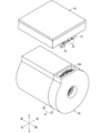
- FIG. 1 is a perspective view showing an integrated mechanical and electrical unit according to an embodiment of the present invention.
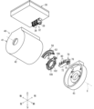
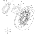
- FIG. 2 is an exploded perspective view showing the electromechanical integrated unit.
- FIG. 3 is an exploded perspective view showing the electromechanical integrated unit.
- FIG. 4 is a perspective view showing a coil end module.
- FIG. 5 is a perspective view showing a portion of the coil end module to which the temperature sensor and the temperature sensor side connector are attached.
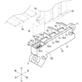
- FIG. 6 is a perspective view showing a terminal block module.
- FIG. 7 is a perspective view showing a terminal block module.
- FIG. 8 is a perspective view showing the connection member.
- FIG. 9 is an exploded perspective view showing the connection member.
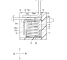
- FIG. 10 is an explanatory diagram showing a state in the middle of connecting the terminal to the connecting member.
- FIG. 10 is an explanatory diagram showing a state in the middle of connecting the terminal to the connecting member.
- FIG. 11 is an explanatory diagram showing a state in which the terminals are connected to the connection member.
- FIG. 12 is a perspective view showing the terminal.
- FIG. 13 is an explanatory diagram showing a state during the manufacturing process of the mechanically and electrically integrated unit.
- FIG. 14 is an explanatory diagram showing a state during the manufacturing process of the mechanically and electrically integrated unit.
- the connecting device for a rotating electric machine disclosed herein is as follows:
- a connecting device for a rotating electric machine that connects a coil wire in an equipment case of a rotating electric machine to an outer bus bar terminal inserted from outside the equipment case
- the connecting device for a rotating electric machine includes a coil end module having a coil end lead terminal connected to the coil wire and a coil end holding portion that supports the coil end lead terminal in a cantilever manner along the direction of the rotation axis of the rotating electric machine, and a terminal block module having a connecting member and a terminal block main body that holds the connecting member, the connecting member having a support member with a bottom and a biasing member, the terminal block module is located next to the coil end module in the direction of the rotation axis, the tip of the coil end lead terminal is located on the opposite side of the bottom with respect to the biasing member, the outer bus bar terminal is located on the opposite side of the biasing member with respect to the coil end lead terminal, the biasing member is interposed between the bottom and the tip of the coil end lead terminal in a compressed state, and biases the tip of the coil end
- the tip of the cantilevered coil end pull-out terminal is pressed against the outer bus bar terminal by a biasing member, connecting the coil end pull-out terminal and the outer bus bar terminal. This eliminates the need to connect a braid or the like to the coil end pull-out terminal, further simplifying the connection structure between the terminals.
- connection member may further have a pressing piece supported by the support member so as to be movable in a direction toward and away from the bottom, the biasing member may be interposed in a compressed state between the bottom and the pressing piece, and the biasing member may bias the tip of the coil end drawer terminal toward the outer bus bar terminal via the pressing piece.
- the biasing member contacts the coil end pull-out terminal via the pressing piece, so the coil end pull-out terminal can be biased toward the outer bus bar terminal in a stable position.
- the support member may support the pressing piece so that it can move back and forth between a standby position and an approach position that is closer to the bottom than the standby position.
- the pressing piece Before the terminals are connected to each other, the pressing piece can be supported so that it can move between a standby position and an approach position, and the biasing member can be supported between the support member and the pressing piece.
- the pressing piece may have a pressing plate portion extending in a direction perpendicular to the biasing direction of the biasing member, and a guide portion having a guide surface that gradually approaches the bottom side in a direction away from the periphery of the pressing plate portion.
- the tip of the coil end pull-out terminal when placing the coil end pull-out terminal on the pressing piece, the tip of the coil end pull-out terminal can be placed on the pressing plate portion while being pressed against the guide portion. This makes it easy to place the tip of the coil end pull-out terminal on the pressing plate portion.
- a connecting device for a rotating electric machine wherein the terminal block body has an inner opening into which the coil end drawer terminal is inserted along the direction of the rotation axis, and an outer opening into which the outer bus bar terminal is inserted from the outer periphery side of the device case toward the inner periphery side, and the tip of the coil end drawer terminal inserted into the terminal block body through the inner opening is pressed against the tip of the outer bus bar terminal inserted into the terminal block body through the outer opening by receiving the biasing force of the biasing member.
- the coil end pull-out terminal supported in a cantilever shape along the rotation axis can move toward the connection member through the inner opening.
- the outer bus bar terminal can move toward the connection member through the outer opening.
- the coil end pull-out terminal and the outer bus bar terminal that have moved toward the connection member are kept in contact with each other by the connection member.
- the terminal block module may have an external signal connector, and the connection direction of the connector from the outside to the external signal connector may be set to follow the insertion of the outer bus bar terminal into the outer opening.
- the terminal block module may have an external signal connector, the external signal connector may have an outer signal terminal, and the signal wiring connected to the outer signal terminal may pass through the terminal block body so as to be directed into the device case.
- the terminal block module may further include a signal internal connector having an inner signal terminal and supported by the terminal block body so as to be positioned within the device case, and the signal wiring may be connected to the inner signal terminal.
- the internal signal connector is placed inside the equipment case.
- the internal signal line is connected to wiring outside the rotating electric machine via the relay signal wiring. Therefore, the signal line incorporated inside the rotating electric machine can be easily connected to wiring outside the rotating electric machine.
- the terminal connection device disclosed herein is as follows:
- a terminal connection device for connecting a first terminal to a second terminal, the terminal connection device comprising: the first terminal supported at a base end in a cantilevered manner; a support member having a bottom; and a connection member having a biasing member, the biasing member being interposed in a compressed state between the bottom and the tip of the first terminal, and biasing the tip of the first terminal against the second terminal disposed on the first terminal.
- the tip of the cantilevered first terminal is pressed against the second terminal by a biasing member to connect the first terminal and the second terminal. This eliminates the need to connect a braid or the like to the first terminal, further simplifying the connection structure between the terminals.
- Fig. 1 is a perspective view showing the electromechanical integrated unit 20.
- Figs. 2 and 3 are exploded perspective views showing the electromechanical integrated unit 20.
- the mechanically and electrically integrated unit 20 is a unit that integrates a rotating electric machine 40 and a control device 30 that controls the rotating electric machine 40.
- the rotating electric machine 40 is a rotating electric machine that includes a device case 41, an armature 46, and a field magnet 49.
- the rotating electric machine 40 may be an electric motor or a generator.
- the device case 41 comprises a cylindrical case body 42 with a bottom and a lid 43.
- An armature 46 serving as a stator is housed within the case body 42.
- a field magnet 49 is disposed within the armature 46 as a rotor. The field magnet 49 rotates due to the magnetic field generated by the armature 46, or the rotation of the field magnet 49 causes the armature 46 to generate an electromotive force.
- the armature 46 includes a coil wire 46a.
- the coil wire 46a is a linear conductive member made of copper wire or the like.
- the coil wire 46a may be wound around an armature core.
- the control device 30 is, for example, an inverter device that drives and controls the rotating electric machine 40. It is assumed that the control device 30 is integrated with the device case 41 of the rotating electric machine 40 by bolting or the like.
- An outer bus bar terminal 38 extends from the control device 30 as a second terminal.
- the coil wire 46a is connected to the outer bus bar terminal 38 via the coil end module 50 and the terminal block module 70.
- the coil end module 50 is located on the opening side of the case body 42 of the armature 46.
- the coil end module 50 has a coil end lead terminal 58 as a first terminal that is connected to the coil wire 46a inside the equipment case 41.
- the coil end lead terminal 58 extends from the armature 46 to the opening side of the case body 42.
- the coil end lead terminal 58 extends to the terminal block module 70 side.
- the coil end lead terminal 58 is an example of an inner bus bar terminal inside the equipment case 41.
- the coil end module 50 may have a configuration that connects the terminals of multiple coil wires 46a of the armature 46.
- the terminal block module 70 is located next to the coil end module 50 in the direction of the rotation axis X of the rotating electric machine 40.
- the terminal block module 70 is attached to the inside of the lid portion 43.
- An opening 43h is formed in the portion of the lid portion 43 that faces the control device 30 relative to the terminal block module 70.
- the outer bus bar terminal 38 extends toward the terminal block module 70 through the opening 43h.
- the coil end pull-out terminal 58 and the outer bus bar terminal 38 are electrically connected by the terminal block module 70.
- the rotating electric machine 40 is a rotating electric machine that can be used as a three-phase AC motor.
- the rotating electric machine 40 has three coil end lead-out terminals 58
- the control device 30 has three outer bus bar terminals 38.
- Each of the three coil end lead-out terminals 58 is electrically connected to each of the three outer bus bar terminals 38 by a terminal block module 70.
- the side of the lid 43 in the direction along the rotation axis X of the rotating electric machine 40 may be referred to as the front side, and the opposite side as the rear side.
- the side of the rotating electric machine 40 in the direction perpendicular to the rotation axis X, the side of the rotating electric machine 40 may be referred to as the bottom side, and the side of the control device 30 may be referred to as the bottom side.
- left and right directions may be mentioned based on the top and bottom and front and back.
- the rotating electric machine 40 also includes a speed sensor 100.
- the speed sensor 100 is a sensor that detects the rotational speed of the field magnet 49 by detecting, for example, the rotation angle of the field magnet 49 as a rotor.
- the speed sensor 100 may be a sensor called a resolver.
- the rotating electric machine 40 also includes a temperature sensor 110.
- the temperature sensor 110 is a sensor that detects the temperature inside the rotating electric machine 40, for example, the temperature of the coil wire 46a.
- the detection signal of the speed sensor 100 and the detection signal of the temperature sensor 110 are provided to the control device 30. This allows the control device 30 to control the rotating electric machine 40 based on the detection signal of the speed sensor 100 and the detection signal of the temperature sensor 110.
- the terminal block module 70 has an internal connector 74 for the speed sensor that is connected to the speed sensor 100 inside the device case 41.
- the terminal block module 70 also has wiring for transmitting the detection signal of the speed sensor 100 to the outside. Therefore, the detection signal of the speed sensor 100 inside the device case 41 can be easily output to the outside via the internal connector 74 for the speed sensor and the wiring.
- the configuration related to the internal connector 74 for the speed sensor and the wiring for it may be configured separately from the terminal block module, or may be omitted.
- the terminal block module 70 also has an internal connector 76 for the temperature sensor that is connected to the temperature sensor 110 inside the device case 41.
- the terminal block module 70 also has wiring for transmitting the detection signal of the temperature sensor 110 to the outside. Therefore, the detection signal of the temperature sensor 110 inside the device case 41 can be easily output to the outside via the internal connector 76 for the temperature sensor and the wiring.
- Fig. 4 is a perspective view showing the coil end module 50.
- Fig. 4 shows a portion of the coil wire 46a extending from the armature 46.
- Fig. 5 is a perspective view showing a portion of the coil end module 50 to which the temperature sensor 110 and the temperature sensor side connector 112 are attached.
- the coil end module 50 has a coil end pull-out terminal 58 and a coil end holding portion 52.
- the coil end lead terminal 58 is connected to the coil wire 46a.
- the coil end holding portion 52 supports the coil end lead terminal 58 in a cantilever manner along the direction of the rotation axis X of the rotating electric machine 40.
- the coil end holding portion 52 is formed of an insulating material such as resin.
- the coil end holding portion 52 is formed with insertion holes 52h into which the multiple coil wires 46a extending from the armature 46 can be inserted. A portion of the ends of the multiple coil wires 46a is shown in FIG. 4.
- the coil end holding portion 52 is arc-shaped so that it can be positioned at a portion of the circumferential direction of the end face of the armature 46 on the lid portion 43 side.
- the coil end holding portion 52 holds the relay bus bar 53.
- the relay bus bar 53 is a conductive member formed of a metal plate such as copper.
- the relay bus bar 53 has a connection end 53a that can be positioned adjacent to the coil wire 46a inserted into the insertion hole 52h.
- the end of the coil wire 46a inserted into the insertion hole 52h is electrically connected to the connection end 53a.
- the coil wire 46a may be joined to the connection end 53a.
- the joining may be Tig welding, laser welding, resistance welding, ultrasonic joining, soldering, or crimping joining.
- the relay bus bar 53 has an intermediate connection portion that connects the multiple connection ends 53a in a predetermined combination. This allows the multiple coil wires 46a connected to the connection ends 53a to be electrically connected in a predetermined combination.
- the coil end pull-out terminals 58 extend from the surface of the lid portion 43 of the coil end holding portion 52. As described above, three coil end pull-out terminals 58 extend from the coil end holding portion 52. The three coil end pull-out terminals 58 are positioned at intervals along an arc whose center of curvature is the rotation axis X. Each coil end pull-out terminal 58 is aligned along the rotation axis X.
- the coil end lead terminal 58 may be connected to the connection end 53a connected to any of the coil wires 46a via an intermediate connection part.
- the coil end lead terminal 58 may be a metal plate part integrally formed with the relay bus bar 53.
- the coil end lead terminal 58 may be directly connected to the coil wire 46a.
- the coil end pull-out terminal 58 is formed in a long, thin plate shape. One main surface of the coil end pull-out terminal 58 faces the inside of the device case 41, and the other main surface faces the outside of the device case 41. Therefore, the coil end pull-out terminal 58 can be deformed so that the tip end is displaced in the inner and outer periphery directions of the device case 41, centering on the base end that is cantilevered by the coil end holding portion 52.
- the coil end module 50 also has a temperature sensor 110 and a temperature sensor side connector 112.
- the temperature sensor 110 is thermally coupled to the coil wire 46a.
- the temperature sensor 110 being thermally coupled to the coil wire 46a means that the temperature sensor 110 is capable of detecting temperature changes in the coil wire 46a.
- the temperature sensor 110 may be in direct contact with the coil wire 46a, or may be in contact via a thermally conductive member such as copper.
- the thermally conductive member that is the subject of temperature measurement by the temperature sensor 110 may be the coil wire 46a itself, the relay bus bar 53 joined to the coil wire 46a, a thermally conductive relay member connected to the coil wire 46a separately from the relay bus bar 53, or a portion of the coil wire 46a that is branched off midway and pulled out.
- the temperature sensor 110 may be, for example, a sensor in which a thermistor element is covered with resin.
- the temperature sensor 110 may be maintained in contact with the coil wire 46a or the thermally conductive member, for example, by the following configuration.
- the temperature sensor 110 may be held in a fixed position by the coil end holding portion 52, and the thermally conductive member may be inserted into the coil end holding portion 52 and held in contact with the temperature sensor 110.
- the temperature sensor 110 and the thermally conductive member may be held by the coil end holding portion 52 in a state of contact with each other, and the thermally conductive member may be joined to the coil wire 46a by welding or the like.
- the thermally conductive member may have a crimping piece, and the crimping piece may be crimped to the temperature sensor 110.
- An electric wire 114 extends from the temperature sensor 110 as an example of wiring.
- a temperature sensor side connector 112 is connected to the end of the electric wire 114.
- the temperature sensor side connector 112 is connected to the temperature sensor 110 via the electric wire 114.
- the coil end holding portion 52 holds the temperature sensor side connector 112 in a position where it can be connected to the temperature sensor internal connector 76 on the terminal block module 70 side.
- the connector holding portion 54 protrudes from a position near one end of the coil end holding portion 52. More specifically, the connector holding portion 54 protrudes from a surface of the coil end holding portion 52 facing the terminal block module 70 side, avoiding the coil wire 46a and the connection end 53a. The connector holding portion 54 protrudes along the rotation axis X.
- An inner connector receiving portion 55 is formed at the tip of the connector holding portion 54.
- the inner connector receiving portion 55 is formed in a box shape that opens toward the terminal block module 70 side.
- the inner circumferential surface of the inner connector receiving portion 55 is larger than the outer circumferential surface of the temperature sensor side connector 112, and the temperature sensor side connector 112 can move in a direction perpendicular to the rotation axis X within the inner connector receiving portion 55.
- An electric wire insertion groove 55g is formed from the peripheral wall to the bottom surface of the inner connector receiving portion 55.
- the electric wire 114 extending from the temperature sensor side connector 112 is routed toward the temperature sensor 110 through the electric wire insertion
- the temperature sensor side connector 112 is held in place by receiving the base end of the temperature sensor side connector 112 in the inner connector receptacle 55. In this state, the temperature sensor side connector 112 can move in a direction perpendicular to the rotation axis X within a range restricted by the inner surface of the inner connector receptacle 55. In addition, movement toward the armature 46 along the direction of the rotation axis X is restricted by the bottom surface of the inner connector receptacle 55.
- the temperature sensor side connector 112 faces the terminal block module 70, and the coil end module 50 and the terminal block module 70 move closer to each other along the rotation axis X, so that the temperature sensor side connector 112 can be connected to the temperature sensor internal connector 76 on the terminal block module 70 side. At this time, the temperature sensor side connector 112 can move in a direction perpendicular to the rotation axis X depending on the position error of both connectors 112, 76.
- a wire support portion 54P capable of supporting the wire 114 may be provided on the outside of the inner connector receiving portion 55 of the connector holding portion 54. By supporting the wire 114 with the wire support portion 54P, it is possible to make it difficult for the temperature sensor side connector 112 to fall off from the inner connector receiving portion 55.
- Terminal block module> 6 and 7 are perspective views showing the terminal block module 70.
- the coil end lead terminals 58 and the outer bus bar terminals 38 are indicated by two-dot chain lines.
- the terminal block module 70 is a member fixed to the device case 41.
- the terminal block module 70 has a connection member 80 and a terminal block main body 72.
- connection member 80 is a member for electrically connecting the coil end pull-out terminal 58 as the inner bus bar terminal and the outer bus bar terminal 38 outside the device case 41.
- the connection member 80 does not need to have the main role of electrically connecting the coil end pull-out terminal 58 and the outer bus bar terminal 38, but may play an auxiliary role. In other words, for example, the connection member 80 does not need to be a conductive path between the coil end pull-out terminal 58 and the outer bus bar terminal 38.
- connection member 80 biases the coil end lead terminal 58 against the outer bus bar terminal 38, thereby ensuring that both terminals 58, 38 are electrically connected.
- FIG. 8 is a perspective view showing the connection member 80.
- FIG. 9 is an exploded perspective view showing the connection member 80.
- the connection member 80 includes a support member 82, a biasing member 86, and a pressing piece 88.
- the support member 82 has a bottom 83 and supports the biasing member 86 on the bottom 83.
- the support member 82 is formed by pressing a metal plate.
- the support member 82 includes a bottom 83 and a pair of side plates 84.
- the bottom 83 is formed in a rectangular plate shape.
- a pair of side plates 84 extend from both sides of the bottom 83 on one main surface of the bottom 83.
- Positioning pieces 83a protrude from both front and rear edges of the bottom 83.
- the biasing member 86 on the bottom 83 is positioned on the bottom 83 while being located between the pair of side plates 84 and the front and rear positioning pieces 83a.
- a guide groove 84g is formed at the tip of the side plate 84, extending in the direction in which the side plate 84 extends.
- a retaining piece 84a protrudes from the upper end of the rear side edge of the bottom 83. The guide groove 84g and the retaining piece 84a regulate the direction and range of movement of the pressing piece 88.
- the biasing member 86 is an elastic member such as a coil spring.
- the biasing member 86 may be a leaf spring, a disc spring, rubber, etc.
- the biasing member 86 is supported on the bottom 83.
- the upper end of the biasing member 86 is positioned farther away from the bottom 83 than the retaining piece 84a.
- the biasing member 86 biases the tip of the coil end pull-out terminal 58 against the outer bus bar terminal 38.
- the biasing member 86 biases the tip of the coil end pull-out terminal 58 against the outer bus bar terminal 38 via the pressing piece 88.
- the pressing piece 88 is supported by the support member 82 so that it can move toward and away from the bottom 83.
- the pressing piece 88 is formed, for example, by pressing a metal plate.
- the pressing piece 88 has a pressing plate portion 88a, a guide portion 88g, and a hanging plate portion 88b.
- the pressing plate portion 88a is a flat plate, and in this case, is a rectangular plate.
- the pressing plate portion 88a is located on the opposite side of the bottom portion 83 with respect to the biasing member 86. In other words, the pressing plate portion 88a is located on the biasing member 86.
- the pressing plate portion 88a is perpendicular to the biasing direction of the biasing member 86, that is, parallel to the bottom portion 83.
- the biasing member 86 is interposed in a compressed state between the pressing plate portion 88a and the bottom portion 83.
- the pressing plate portion 88a moves toward or away from the bottom portion 83 as the biasing member 86 expands and contracts, the pressing plate portion 88a comes into contact with the inner surfaces of the pair of side plates 84, and the pressing plate portion 88a is positioned in the left-right direction.
- protrusions 88ap protrude from both sides of the pressing plate portion 88a.
- the protrusions 88ap move along the guide groove 84g.
- the protrusions 88ap come into contact with both side edges of the guide groove 84g on the left and right sides of the pressing plate portion 88a, thereby positioning the pressing plate portion 88a in the front-rear direction.
- the guide portion 88g extends from the rear side of the periphery of the pressing plate portion 88a, i.e., the edge on the coil end module 50 side.
- the guide portion 88g extends so as to gradually approach the bottom portion 83 in the direction away from the pressing plate portion 88a.
- the guide portion 88g extends rearward and downward from the rear edge of the pressing plate portion 88a while forming a partial cylindrical shape.
- the hanging plate portion 88b extends from the tip edge of the guide portion 88g toward the bottom portion 83 along the biasing direction of the biasing member 86.
- the hanging plate portion 88b covers the biasing member 86 from the coil end module 50 side.
- Protrusions 88bp protrude from the upper part of both side edges of the hanging plate portion 88b.
- the protrusions 88bp move up and down along the rear edge of the side plate 84 and contact the above-mentioned anti-pullout piece 84a from the bottom 83 side.
- the protrusions 88bp come into contact with the anti-pullout piece 84a, the movement of the pressing piece 88 in the direction away from the bottom 83 is restricted.
- the standby position is a position where the protrusion 88bp contacts the retaining piece 84a from the bottom 83 side.
- the standby position is a position where the protrusion 88ap contacts the edge of the guide groove 84g on the bottom 83 side.
- the terminal block body 72 is made of resin or the like, and is fixed to the lid 43 of the device case 41 while holding the connection member 80.
- the terminal block body 72 is formed in an elongated shape.
- the terminal block body 72 is formed with an accommodating recess 73 for accommodating the connecting member 80.
- the terminal block body 72 is formed with three accommodating recesses 73 aligned along the extension direction of the terminal block body 72 in order to hold three connecting members 80.
- the terminal block body 72 is integrally formed with a screw fastening portion 71 as an attachment portion.
- the terminal block body 72 is fixed to the lid portion 43 by screw fastening via the screw fastening portion 71.
- the terminal block body 72 has an inner opening 73h1 and an outer opening 73h2.
- Each storage recess 73 opens at the inner opening 73h1 and the outer opening 73h2.
- the inner opening 73h1 is an opening that receives the coil end lead terminal 58, which is an inner bus bar terminal, along the rotation axis X. In other words, the inner opening 73h1 opens on the forward extension of the coil end lead terminal 58.
- the outer opening 73h2 is an opening that receives the outer bus bar terminal 38 along the direction from the outer periphery to the inner periphery of the device case 41. In other words, the outer opening 73h2 opens on the extension of the outer bus bar terminal 38 extending from the control device 30 attached to the rotating electric machine 40.
- the coil end module 50 is attached to the end of the armature 46 inside the case body 42.
- the terminal block module 70 is attached to the lid 43.
- the coil end drawer terminal 58 is guided onto the pressing piece 88 through the inner opening 73h1 as shown in Figs. 10 and 11.
- the tip of the coil end drawer terminal 58 comes into contact with the guide 88g. Since the coil end drawer terminal 58 is supported in a cantilevered manner, the coil end drawer terminal 58 can be tilted so that the tip of the coil end drawer terminal 58 is displaced upward. As a result, the tip of the coil end drawer terminal 58 can be guided by the guide 88g and moved onto the pressing plate 88a.
- the coil end pull-out terminal 58 is positioned on the opposite side of the bottom 83 from the biasing member 86.
- the outer bus bar terminal 38 moves onto the connection member 80 through the outer opening 73h2.
- the outer bus bar terminal 38 is positioned on the opposite side of the biasing member 86 from the coil end pull-out terminal 58.
- the lower end position of the outer bus bar terminal 38 is set to a position that can compress the biasing member 86, taking into account the thickness of the coil end pull-out terminal 58 and the thickness of the pressing plate portion 88a.
- a gap smaller than the thickness of the coil end pull-out terminal 58 is formed between the lower end position of the outer bus bar terminal 38 and the pressing plate portion 88a.
- the lower end of the outer bus bar terminal 38 presses the biasing member 86 downward via the coil end pull-out terminal 58 and the pressing plate portion 88a, compressing the biasing member 86.
- the coil end pull-out terminal 58 is supported in a cantilevered manner, when it is pressed by the outer bus bar terminal 38, it can tilt around its base end.
- the pressing plate portion 88a tries to move upward due to the biasing force of the biasing member 86 trying to return to its original length.
- This biasing force presses the coil end pull-out terminal 58 against the outer bus bar terminal 38.
- the biasing member 86 constantly biases the coil end pull-out terminal 58 against the outer bus bar terminal 38. This ensures that the coil end pull-out terminal 58 and the outer bus bar terminal 38 are kept more reliably electrically connected.
- the pressing plate portion 88a of the pressing piece 88 is interposed between the biasing member 86 and the coil end pull-out terminal 58.
- the pressing piece 88 may be omitted, and the biasing member 86 may press the coil end pull-out terminal 58 directly toward the outer bus bar terminal 38.
- the rotating electric machine connection device 28 has a configuration in which the connection member 80 of the terminal block module 70 biases the coil end lead terminal 58 of the coil end module 50 to the outer bus bar terminal 38.
- This configuration may be applied to equipment other than the rotating electric machine 40 as a connection device for biasing the first terminal and the second terminal with the connection member to maintain an electrical connection state.
- the base end of the first terminal and the support member are supported in a fixed positional relationship by the first support member, and the second terminal and the support member are supported in a fixed positional relationship by the second support member.
- the equipment case 41 and the housing of the control equipment 30 are examples of the first support member and the second support member.
- the terminal block module 70 has a configuration for drawing out the speed sensor 100 inside the device case 41 to the outside.
- the terminal block module 70 includes an internal connector 74 for the speed sensor and wiring 60 for the speed sensor.
- An extension 72E is molded integrally with one end of the terminal block body 72.
- An internal connector 74 for the speed sensor is formed in the extension 72E.
- the speed sensor internal connector 74 has a speed sensor inner terminal 75, and is supported by the terminal block body 72 so as to be located inside the device case 41.
- the speed sensor internal connector 74 is configured to be able to connect to the speed sensor side connector 106 of the speed sensor 100.
- the speed sensor internal connector 74 has an internal connector housing 74a and an internal terminal 75 for the speed sensor.
- the internal connector housing 74a has a recess into which the speed sensor side connector 106 can be inserted.
- the internal terminal 75 for the speed sensor protrudes from the bottom of the recess of the internal connector housing 74a.
- the terminal block body 72 supports the speed sensor internal connector 74 in a position facing the speed sensor side connector 106 of the speed sensor 100 that is installed in the device case 41.
- the connection direction of the speed sensor side connector 106 to the speed sensor internal connector 74 is set to be along the rotation axis X.
- the speed sensor 100 has an annular main body 102, a connector support 104 that protrudes outward from a portion of the circumference of the annular main body 102, and a speed sensor side connector 106 supported at the tip of the connector support 104 (see FIG. 13).
- the annular main body 102 has, for example, portions around which a coil wire is wound arranged in a ring shape. A current excited in the coil wire as the field magnet 49 rotates is output via the speed sensor side connector 106. Note that it is not essential that the speed sensor 100 has the above configuration, and a speed sensor that uses an optical sensor, a magnetic sensor, etc. may also be used.
- the annular body 102 has a screw portion 103 as an attachment portion, and is attached to the cover 43 using the screw portion 103.
- the speed sensor side connector 106 is located on the outside of the annular body 102.
- the speed sensor internal connector 74 has a shape that is long in the tangent direction of a circle centered on the rotation axis X in a plane perpendicular to the rotation axis X.
- Both the terminal block module 70 and the speed sensor 100 are attached to the lid 43.
- the position of the speed sensor internal connector 74 in the terminal block module 70 is a position facing the speed sensor side connector 106 when attached to the lid 43.
- the speed sensor internal connector 74 faces rearward along the rotation axis X, and the speed sensor side connector 106 faces forward along the rotation axis X. Therefore, when the terminal block module 70 and the speed sensor 100 are attached to the lid 43, the speed sensor internal connector 74 and the speed sensor side connector 106 face each other along the rotation axis X and are connected to each other.
- At least a portion of the speed sensor wiring 60 is held within the terminal block body 72, and the speed sensor inner terminal 75 is connected to a terminal of the outer connector, which is a circuit from outside the device case 41. Note that multiple speed sensor wirings 60 are provided corresponding to the multiple speed sensor inner terminals 75 (only a portion is shown in FIG. 6).
- the speed sensor wiring 60 may be a portion punched into a line from a metal plate such as copper, a metal wire, or an electric wire made of metal wire coated with resin. In this embodiment, it is assumed that the speed sensor wiring 60 is a portion punched into a line from a metal plate such as copper.
- the terminal block body 72 is also assumed to be a resin part molded with at least a portion of the speed sensor wiring 60 as an insert part.
- the terminal block body 72 is a part having a through hole through which the speed sensor wiring can pass, and may be configured such that, with the speed sensor wiring disposed within the through hole, the gap between the wiring and the through hole is filled with a filler or the like.
- the terminal block module 70 also has an external connector 78 having an outer terminal 79t1 for the speed sensor.
- the outer terminal 79t1 for the speed sensor is connected to the speed sensor wiring 60.
- a plurality of outer terminals 79t1 for the speed sensor are provided corresponding to the number of inner terminals 75 for the speed sensor.
- the external connector 78 is a part supported by the terminal block main body 72 so that an outer connector 39 can be connected from outside the device case 41.
- the external connector 78 has an external connector housing 78a and an outer terminal 79t1 for the speed sensor.
- the external connector housing 78a is a part that is molded integrally with the extension 72E of the terminal block main body 72, and has a recess into which the outer connector 39 can be inserted.
- the outer terminal 79t1 for the speed sensor protrudes from the bottom of the recess of the external connector housing 78a.
- the terminal block body 72 supports the external connector 78 at a position facing the outer connector 39 on the control device 30 side attached to the device case 41.
- the control device 30 supports the outer connector 39 at a position next to the outer bus bar terminal 38.
- the outer connector 39 is supported on the rotating electric machine 40 side, i.e., facing downward, and the connection direction of the outer connector 39 to the external connector 78 is set to a direction perpendicular to the rotation axis X, here, the up-down direction.
- the connection direction of the outer connector 39 to the external connector 78 is set to be along the direction from the outer periphery side to the inner periphery side of the device case 41.
- the insertion direction of the outer bus bar terminal 38 into the outer opening 73h2 is the direction from the outer periphery side to the inner periphery side of the device case 41.
- the insertion direction of the outer connector 39 into the external connector 78 is set to be along the insertion direction of the outer bus bar terminal 38.
- the control device 30 When the rotating electric machine 40 is assembled, the control device 30 is attached to the rotating electric machine 40. At this time, the outer connector 39 is inserted from above into the external connector 78 through the opening 43h of the cover portion 43. When the control device 30 is attached to the rotating electric machine 40, the outer connector 39 faces the external connector 78 and they are connected to each other.
- the speed sensor side connector 106 of the speed sensor 100 is connected to the speed sensor internal connector 74, and the outer connector 39 is connected to the external connector 78.
- the speed sensor inner terminal 75 of the speed sensor internal connector 74 and the speed sensor outer terminal 79t1 of the external connector 78 are connected via the speed sensor wiring 60.
- the speed sensor internal connector 74, external connector 78, and speed sensor wiring 60 are integrally incorporated into the terminal block module 70. Therefore, the speed sensor 100 is connected to the control device 30 via the terminal block module 70.
- the speed sensor inner terminal 75, the speed sensor outer terminal 79t1, and the speed sensor wiring 60 may be integrally formed as a metal wiring member.
- a metal plate such as copper may be pressed to form a metal wiring member in which the speed sensor inner terminal 75, the speed sensor wiring 60, and the speed sensor outer terminal 79t1 are connected in this order.
- the terminal block body 72, the internal connector housing 74a, and the external connector housing 78a may be molded integrally with resin.
- the speed sensor inner terminal 75 may be located in the internal connector housing 74a
- the speed sensor outer terminal 79t1 may be located in the external connector housing 78a
- the speed sensor wiring 60 may be embedded in the terminal block body 72 (here, the extension portion 72E) as an insert portion. This allows the speed sensor inner connector 74 and the external connector 78 to be easily integrally formed in the terminal block module 70.
- the terminal block body 72 may be formed by multiple mold moldings, such as two-color molding or double molding.
- the speed sensor wiring 60 can also be understood to pass through the terminal block body 72 from the speed sensor outer terminal 79t1 toward the inside of the device case 41.
- the terminal block module 70 also has a configuration for pulling out the temperature sensor 110 inside the device case 41 to the outside.
- the terminal block module 70 includes an internal connector 76 for the temperature sensor and wiring 62 for the temperature sensor.
- An internal connector 76 for the temperature sensor is formed on the extension 72E at one end of the terminal block body 72.
- the temperature sensor internal connector 76 has an inner terminal 77 for the temperature sensor, and is supported by the terminal block body 72 so as to be located inside the device case 41.
- the temperature sensor internal connector 76 is configured to be able to connect to the temperature sensor side connector 112 of the temperature sensor 110.
- the temperature sensor internal connector 76 has an internal connector housing 76a and an internal terminal 77 for the temperature sensor.
- the internal connector housing 76a has a recess into which the temperature sensor side connector 112 can be inserted.
- the internal terminal 77 for the temperature sensor protrudes from the bottom of the recess of the internal connector housing 76a.
- the terminal block body 72 supports the temperature sensor internal connector 76 in a position facing the temperature sensor side connector 112 of the temperature sensor 110 incorporated in the device case 41.
- the connection direction of the temperature sensor side connector 112 to the temperature sensor internal connector 76 is set to be along the direction of the rotation axis X.
- the temperature sensor 110 is held by the coil end module 50, and the temperature sensor side connector 112 is also held by the coil end module 50.
- the temperature sensor side connector 112 faces forward along the rotation axis X.
- the position at which the temperature sensor side connector 112 is supported is on the outer periphery of the speed sensor side connector 106.
- the temperature sensor internal connector 76 faces rearward along the rotation axis X, and therefore faces the temperature sensor side connector 112.
- the temperature sensor side connector 112 and the temperature sensor internal connector 76 move toward each other, and the two connectors 76, 112 are connected. At this time, because the temperature sensor side connector 112 is movably supported by the connector holding portion 54, even if a position error occurs between the two connectors 76, 112, the temperature sensor side connector 112 can be displaced up and down or left and right to match the position of the temperature sensor internal connector 76.
- At least a portion of the temperature sensor wiring 62 is held within the terminal block body 72, and the temperature sensor inner terminal 77 is connected to the wiring on the outer connector side, which is a circuit from outside the device case 41. Note that multiple temperature sensor wirings 62 are provided corresponding to the multiple temperature sensor inner terminals 77, respectively.
- the temperature sensor wiring 62 may be a portion punched into a line from a metal plate such as copper, a metal wire, or an electric wire made of metal wire coated with resin. In this embodiment, it is assumed that the temperature sensor wiring 62 is a portion punched into a line from a metal plate such as copper.
- the terminal block body 72 is also assumed to be a resin part molded with at least a part of the temperature sensor wiring 62 as an insert part.
- the terminal block body 72 is a part having a through hole through which the temperature sensor wiring can pass, and may be configured such that with the temperature sensor wiring disposed in the through hole, the gap between the wiring and the through hole is filled with a filler or the like.
- the terminal block module 70 also has an external connector 78 having an external terminal 79t2 for the temperature sensor.
- the external terminal 79t2 for the temperature sensor is connected to the temperature sensor wiring 62.
- a plurality of external terminals 79t2 for the temperature sensor are provided corresponding to the number of internal terminals 77 for the temperature sensor.
- the external connector 78 is a portion supported by the terminal block main body 72 so that an external connector 39 can be connected from outside the device case 41.
- the external connector 78 has an external connector housing 78a and an outer terminal 79t2 for a temperature sensor.
- the external connector housing 78a is a connector housing having an outer terminal 79t1 for a speed sensor.
- the outer terminal 79t2 for a temperature sensor protrudes from the bottom of a recess in the external connector housing 78a.
- the external connector 78 has an outer terminal 79t1 for a speed sensor and an outer terminal 79t2 for a temperature sensor, and is a connector for outputting both a speed detection signal and a temperature detection signal.
- the outer connector 39 is inserted and connected into the external connector housing 78a, and the outer terminal 79t2 for the temperature sensor is connected to the terminal on the outer connector 39 side.
- the temperature sensor side connector 112 of the temperature sensor 110 is connected to the temperature sensor internal connector 76, and the outer connector 39 is connected to the external connector 78.
- the temperature sensor inner terminal 77 of the temperature sensor internal connector 76 and the temperature sensor outer terminal 79t2 of the external connector 78 are connected via the temperature sensor wiring 62.
- the temperature sensor internal connector 76, external connector 78, and temperature sensor wiring 62 are integrally incorporated into the terminal block module 70. Therefore, the temperature sensor 110 is connected to the control device 30 via the terminal block module 70.
- the temperature sensor inner terminal 77, the temperature sensor outer terminal 79t2, and the temperature sensor wiring 62 may be integrally formed as a metal wiring member.
- a metal plate such as copper may be pressed to form a metal wiring member in which the temperature sensor inner terminal 77, the temperature sensor wiring 62, and the temperature sensor outer terminal 79t2 are connected in this order.
- the terminal block body 72, the internal connector housing 76a, and the external connector housing 78a may be molded integrally with resin.
- the temperature sensor inner terminal 77 may be located in the internal connector housing 76a
- the temperature sensor outer terminal 79t2 may be located in the external connector housing 78a
- the temperature sensor wiring 62 may be embedded in the terminal block body 72 (here, the extension portion 72E) as an insert portion. This allows the temperature sensor inner connector 76 and the external connector 78 to be easily integrally formed in the terminal block module 70.
- the terminal block body 72 may be formed by multiple mold moldings, such as two-color molding (double molding).
- the temperature sensor wiring 62 can also be understood to pass through the terminal block body 72 from the temperature sensor outer terminal 79t2 toward the inside of the device case 41.
- the external connector 78 is an example of an external connector for a speed sensor in that it has an outer terminal 79t1 for a speed sensor. Also, the external connector 78 is an example of a connector for a temperature sensor in that it has an outer terminal 79t2 for a temperature sensor.
- the external connector 78 is used as a connector that outputs both temperature and speed detection signals, but the external connector may be divided into a connector having an external terminal for the speed sensor and a connector having an external terminal for the temperature sensor.
- Fig. 12 is a perspective view showing the terminal 32.
- the control device 30 is a device that controls the rotating electric machine 40, and has an inverter control board.
- the control device 30 has the terminal 32 that connects the inverter control board and the rotating electric machine 40.
- the terminal 32 has a base member 33, multiple (here, three) outer bus bar terminals 38, and a signal relay section 36.
- the base member 33 has a base plate portion 33a and a column portion 33b that protrudes from the base plate portion 33a toward the rotating electric machine 40.
- the base plate portion 33a is fixed to the case of the control device 30 by screws or the like.
- the outer bus bar terminal 38 is formed from a metal plate such as a copper plate.
- the outer bus bar terminal 38 has an elongated plate-shaped middle portion and upper and lower ends that bend and extend from both ends of the elongated plate-shaped middle portion toward one main surface of the plate-shaped middle portion.
- the upper end of the outer bus bar terminal 38 is disposed on the base plate portion 33a and is connected by screws or the like to the bus bar 130 extending from the inverter control board.
- the plate-shaped middle portion of the outer bus bar terminal 38 extends along the front side surface of the pillar portion 33b.
- the lower end of the outer bus bar terminal 38 is disposed so as to overlap the lower surface of the base plate portion 33a.
- the signal relay unit 36 has an outer connector 39, a board-side connector 37, and wiring 36W connecting the two connectors.
- the wiring 36W is, for example, an electric wire.
- the outer connector 39 is supported by a connector support portion 35 located on one side of the base member 33.
- the connector support portion 35 is located on the outside in the direction in which the multiple pillar portions 33b are arranged.
- the lower end portion of the connector support portion 35 faces the external connector 78 in the terminal block module 70.
- a box-shaped connector receptacle 35R that opens downward is formed at the lower end portion of the connector support portion 35.
- the inner wall surface of the connector receptacle 35R is larger than the outer surface of the outer connector 39.
- the connector receptacle 35R supports the outer connector 39 in a state that allows the outer connector 39 to move in the front-rear and left-right directions.
- the wiring 36W extends from the outer connector 39 upward through the connector receptacle 35R and onto the base plate portion 33a.
- a connector receiving portion 34R having the same configuration as the connector receiving portion 35R is provided on the base plate portion 33a.
- the board-side connector 37 is supported by the connector receiving portion 34R in a state in which it is permitted to move in the upper, left, and right directions.
- the connector 131 on the inverter control board is connected to the board-side connector 37.
- the coil end module 50 is attached to the end of the coil wire 46a of the armature 46 (see FIG. 4). This connects the coil wires 46a together in a predetermined combination. In addition, a portion of the coil wire 46a is connected to the coil end lead terminal 58.
- the armature 46 may be assembled into the case body 42 either before or after the coil end module 50 is attached.
- the terminal block module 70 is attached to the cover 43 by means of screws or the like.
- the speed sensor internal connector 74 and the temperature sensor internal connector 76 of the terminal block module 70 face rearward along the rotation axis X.
- the inner opening 73h1 of the terminal block main body 72 faces rearward along the rotation axis X
- the outer opening 73h2 faces towards the opening 43h, i.e., outward.
- the external connector 78 faces towards the opening 43h, i.e., outward.
- the speed sensor side connector 106 is connected to the speed sensor internal connector 74 and fixed to the lid 43 by screwing or the like. With the terminal block module 70 and the speed sensor side connector 106 attached to the lid 43, the speed sensor side connector 106 and the speed sensor internal connector 74 face each other along the rotation axis X. Therefore, by moving the speed sensor 100 along the rotation axis X toward the lid 43, the two connectors 74, 106 can be easily connected.
- the speed sensor side connector 106 and the speed sensor internal connector 74 may be connected, and the combination of the terminal block module 70 and the speed sensor 100 may be attached to the lid 43 by means of screws or the like.
- the coil end module 50 may be attached to the armature 46 first, and the terminal block module 70 or the speed sensor 100 may be attached to the cover 43 first.
- the speed sensor integrated terminal block module 44 As described above, when the speed sensor side connector 106 and the speed sensor internal connector 74 are connected, the terminal block module 70 and the speed sensor 100 are integrated into one unit, which is called the speed sensor integrated terminal block module 44 (see Figure 13).
- the cover 43 is fixed to the case body 42 by screws or the like so as to close the front opening of the case body 42.
- the tip of the coil end pull-out terminal 58 passes through the inner opening 73h1 along the rotation axis X, is inserted into the recess 73 of the terminal block body 72, and is positioned on the connection member 80.
- the tip of the coil end pull-out terminal 58 is positioned above the pressing piece 88.
- the temperature sensor side connector 112 is also connected to the temperature sensor internal connector 76 along the rotation axis X. At this time, the temperature sensor side connector 112 can move within the inner connector receiving portion 55. Therefore, even if there is a positional misalignment between the connectors 76, 112, the temperature sensor side connector 112 can be displaced to match the position of the temperature sensor internal connector 76. This allows the connectors 76, 112 to be more securely connected.
- the control device 30 is attached to the rotating electric machine 40 by means of screws or the like.
- the terminal 32 is inserted into the rotating electric machine 40 through the opening 43h.
- the outer bus bar terminal 38 is inserted into the recess 73 of the terminal block main body 72 through the outer opening 73h2 and pressed against the upper surface of the coil end drawer terminal 58 located on the connection member 80.
- the outer bus bar terminal 38 presses the biasing member 86 via the tip of the coil end drawer terminal 58.
- the coil end drawer terminal 58 tilts with the base end as a fulcrum, displacing the tip in the downward direction. Since the biasing member 86 is compressed, the biasing force of the biasing member 86 keeps the tip of the coil end drawer terminal 58 pressed against the tip of the outer bus bar terminal 38.
- the outer connector 39 also moves through the opening 43h toward the external connector 78 and is connected to the external connector 78. As described above, the outer connector 39 is supported by the connector receiving portion 35R so that it can move in a direction perpendicular to the connection direction. Therefore, even if there is a positional misalignment between the connectors 39 and 78, the outer connector 39 can be displaced to match the position of the external connector 78. This allows the connectors 39 and 78 to be more reliably connected.
- the tip of the cantilevered coil end lead terminal 58 is pressed against the outer bus bar terminal 38 by the biasing member 86 to connect the coil end lead terminal 58 and the outer bus bar terminal 38.
- the coil end lead terminal 58 is pressed against the outer bus bar terminal 38 by the biasing force of the biasing member 86, utilizing the fact that the tip of the cantilevered coil end lead terminal 58 can be displaced in the biasing direction.
- the coil end lead terminal 58 is maintained in a state electrically connected to the outer bus bar terminal 38.
- the biasing member 86 contacts the coil end pull-out terminal 58 via the pressing piece 88, the coil end pull-out terminal 58 can be biased toward the outer bus bar terminal 38 in a stable position compared to when a biasing member 86 such as a coil spring contacts the coil end pull-out terminal 58.
- the support member 82 supports the pressing piece 88 so that it can move back and forth between the standby position and the approach position, so that the biasing member 86 can be supported between the support member 82 and the pressing piece 88.
- the connection work of the coil end drawer terminal 58 and the outer bus bar terminal 38 can be easily performed.
- the pressing piece 88 has a pressing plate portion 88a and a guide portion 88g, when the coil end drawing terminal 58 is placed on the pressing piece 88, the tip of the coil end drawing terminal 58 can be placed on the pressing plate portion 88a while being pressed against the guide portion 88g. This makes it easy to place the tip of the coil end drawing terminal 58 on the pressing plate portion 88a.
- the coil end lead-out terminal 58 is inserted into the terminal block body 72 through the inner opening 73h1 and placed on the connection member 80.
- the outer bus bar terminal 38 is inserted into the terminal block body 72 through the outer opening 73h2 and placed on the coil end lead-out terminal 58.
- the coil end lead-out terminal 58 and the outer bus bar terminal 38 are kept in contact with each other by the connection member 80.
- connection direction of the outer connector 39 to the external connector 78 is set to be along the insertion direction of the outer bus bar terminal 38 to the outer opening 73h2
- connection work of the outer connector 39 to the external connector 78 and the outer bus bar terminal 38 can be easily performed by connection work in the same direction.
- the wiring 60, 62 connected to the outer terminals 79t1, 79t2 of the external connector 78 passes through the terminal block body 72 so as to face the inside of the device case 41. This makes it easy to incorporate signal wiring into the rotating electric machine 40.
- the terminal block module 70 also supports the speed sensor internal connector 74 and the temperature sensor internal connector 76 so that they are positioned within the device case 41. Therefore, when the terminal block main body 72 that holds the connection member 80 is fixed to the device case 41, the speed sensor internal connector 74 and the temperature sensor internal connector 76 are positioned within the device case 41. Then, when the connectors for signals within the device, i.e., the connectors 106, 112 of the sensors 100, 110, are connected to the speed sensor internal connector 74 and the temperature sensor internal connector 76, the internal signals can be output outside the rotating electric machine 40 via the signal wiring 60, 62. In this way, the signal lines incorporated within the rotating electric machine 40 can be easily connected to wiring outside the rotating electric machine 40.
- the rotating electric machine connection device 28 is applied as a connection device between a first terminal and a second terminal, rather than to a rotating electric machine 40, the first terminal supported by a cantilever can be pressed against the second terminal by a biasing member to connect the first terminal and the second terminal. This makes it possible to more reliably connect the terminals together without supporting the first terminal with a complex movable structure or connecting a braid or the like for movement. This further simplifies the terminal connection structure.
Landscapes
- Engineering & Computer Science (AREA)
- Power Engineering (AREA)
- Motor Or Generator Frames (AREA)
Priority Applications (2)
| Application Number | Priority Date | Filing Date | Title |
|---|---|---|---|
| CN202380085720.XA CN120419080A (zh) | 2022-12-22 | 2023-11-02 | 旋转电机用连接装置及端子的连接装置 |
| JP2024565644A JPWO2024135116A1 (https=) | 2022-12-22 | 2023-11-02 |
Applications Claiming Priority (2)
| Application Number | Priority Date | Filing Date | Title |
|---|---|---|---|
| JP2022-205345 | 2022-12-22 | ||
| JP2022205345 | 2022-12-22 |
Publications (1)
| Publication Number | Publication Date |
|---|---|
| WO2024135116A1 true WO2024135116A1 (ja) | 2024-06-27 |
Family
ID=91588356
Family Applications (1)
| Application Number | Title | Priority Date | Filing Date |
|---|---|---|---|
| PCT/JP2023/039627 Ceased WO2024135116A1 (ja) | 2022-12-22 | 2023-11-02 | 回転電機用接続装置及び端子の接続装置 |
Country Status (3)
| Country | Link |
|---|---|
| JP (1) | JPWO2024135116A1 (https=) |
| CN (1) | CN120419080A (https=) |
| WO (1) | WO2024135116A1 (https=) |
Citations (5)
| Publication number | Priority date | Publication date | Assignee | Title |
|---|---|---|---|---|
| JP2005229755A (ja) * | 2004-02-13 | 2005-08-25 | Toyota Motor Corp | モータモジュール |
| JP2012100381A (ja) * | 2010-10-29 | 2012-05-24 | Toyota Motor Corp | 回転電機用端子台 |
| JP2015109742A (ja) * | 2013-12-04 | 2015-06-11 | 日産自動車株式会社 | 回転電機の端子接続構造 |
| WO2016199219A1 (ja) * | 2015-06-09 | 2016-12-15 | 日産自動車株式会社 | 機電一体型の回転電機装置 |
| JP2019153565A (ja) * | 2018-03-02 | 2019-09-12 | 株式会社オートネットワーク技術研究所 | 雌端子 |
-
2023
- 2023-11-02 CN CN202380085720.XA patent/CN120419080A/zh active Pending
- 2023-11-02 JP JP2024565644A patent/JPWO2024135116A1/ja active Pending
- 2023-11-02 WO PCT/JP2023/039627 patent/WO2024135116A1/ja not_active Ceased
Patent Citations (5)
| Publication number | Priority date | Publication date | Assignee | Title |
|---|---|---|---|---|
| JP2005229755A (ja) * | 2004-02-13 | 2005-08-25 | Toyota Motor Corp | モータモジュール |
| JP2012100381A (ja) * | 2010-10-29 | 2012-05-24 | Toyota Motor Corp | 回転電機用端子台 |
| JP2015109742A (ja) * | 2013-12-04 | 2015-06-11 | 日産自動車株式会社 | 回転電機の端子接続構造 |
| WO2016199219A1 (ja) * | 2015-06-09 | 2016-12-15 | 日産自動車株式会社 | 機電一体型の回転電機装置 |
| JP2019153565A (ja) * | 2018-03-02 | 2019-09-12 | 株式会社オートネットワーク技術研究所 | 雌端子 |
Also Published As
| Publication number | Publication date |
|---|---|
| CN120419080A (zh) | 2025-08-01 |
| JPWO2024135116A1 (https=) | 2024-06-27 |
Similar Documents
| Publication | Publication Date | Title |
|---|---|---|
| CN101926074B (zh) | 马达 | |
| EP3584912B1 (en) | Motor for driving a lens | |
| CN101322305B (zh) | 用于驱动镜头的马达 | |
| KR101675355B1 (ko) | 모터 | |
| WO2009113629A1 (ja) | モータ | |
| JP4082259B2 (ja) | 回転電機 | |
| JP6856067B2 (ja) | モータ及びモータの製造方法 | |
| WO2024135116A1 (ja) | 回転電機用接続装置及び端子の接続装置 | |
| JP2019030143A (ja) | コネクタ及びコネクタを備えたモータ | |
| JP2019030141A (ja) | コネクタ及びコネクタを備えたモータ | |
| WO2024135117A1 (ja) | 端子台モジュール、回転電機用配線ユニット及びコイルエンドモジュール | |
| WO2024135118A1 (ja) | 端子台モジュール及び速度センサ一体型端子台モジュール | |
| US12261503B2 (en) | Electric motor comprising a housing with a stator overmolding and connection assemblies | |
| WO2025074847A1 (ja) | 中継コネクタ、端子台モジュール、コイルエンドモジュール及び接続モジュール | |
| WO2024150664A1 (ja) | 回転電機用接続ユニット | |
| CN110011464B (zh) | 用于电机的电刷架-构件以及电机 | |
| WO2021157400A1 (ja) | 電気接続箱 | |
| JP7418243B2 (ja) | モールドコネクタ | |
| CN220553906U (zh) | 安装构造 | |
| JP4397900B2 (ja) | 駆動装置用モータ | |
| JP4319300B2 (ja) | 駆動装置用モータ | |
| JP4397903B2 (ja) | 駆動装置用モータ | |
| JP4397901B2 (ja) | 駆動装置用モータ | |
| JP2003164098A (ja) | モータの電力供給構造 | |
| JP4397902B2 (ja) | 駆動装置用モータ |
Legal Events
| Date | Code | Title | Description |
|---|---|---|---|
| 121 | Ep: the epo has been informed by wipo that ep was designated in this application |
Ref document number: 23904817 Country of ref document: EP Kind code of ref document: A1 |
|
| WWE | Wipo information: entry into national phase |
Ref document number: 2024565644 Country of ref document: JP |
|
| WWE | Wipo information: entry into national phase |
Ref document number: 202380085720.X Country of ref document: CN |
|
| NENP | Non-entry into the national phase |
Ref country code: DE |
|
| WWP | Wipo information: published in national office |
Ref document number: 202380085720.X Country of ref document: CN |
|
| 122 | Ep: pct application non-entry in european phase |
Ref document number: 23904817 Country of ref document: EP Kind code of ref document: A1 |