WO2024128319A1 - 蓄電体用積層体及びその用途 - Google Patents
蓄電体用積層体及びその用途 Download PDFInfo
- Publication number
- WO2024128319A1 WO2024128319A1 PCT/JP2023/045124 JP2023045124W WO2024128319A1 WO 2024128319 A1 WO2024128319 A1 WO 2024128319A1 JP 2023045124 W JP2023045124 W JP 2023045124W WO 2024128319 A1 WO2024128319 A1 WO 2024128319A1
- Authority
- WO
- WIPO (PCT)
- Prior art keywords
- laminate
- cellulose
- electrode
- layer
- cellulose fiber
- Prior art date
- Legal status (The legal status is an assumption and is not a legal conclusion. Google has not performed a legal analysis and makes no representation as to the accuracy of the status listed.)
- Ceased
Links
Images


Classifications
-
- H—ELECTRICITY
- H01—ELECTRIC ELEMENTS
- H01G—CAPACITORS; CAPACITORS, RECTIFIERS, DETECTORS, SWITCHING DEVICES, LIGHT-SENSITIVE OR TEMPERATURE-SENSITIVE DEVICES OF THE ELECTROLYTIC TYPE
- H01G11/00—Hybrid capacitors, i.e. capacitors having different positive and negative electrodes; Electric double-layer [EDL] capacitors; Processes for the manufacture thereof or of parts thereof
- H01G11/22—Electrodes
- H01G11/30—Electrodes characterised by their material
- H01G11/48—Conductive polymers
-
- H—ELECTRICITY
- H01—ELECTRIC ELEMENTS
- H01G—CAPACITORS; CAPACITORS, RECTIFIERS, DETECTORS, SWITCHING DEVICES, LIGHT-SENSITIVE OR TEMPERATURE-SENSITIVE DEVICES OF THE ELECTROLYTIC TYPE
- H01G11/00—Hybrid capacitors, i.e. capacitors having different positive and negative electrodes; Electric double-layer [EDL] capacitors; Processes for the manufacture thereof or of parts thereof
- H01G11/54—Electrolytes
-
- H—ELECTRICITY
- H01—ELECTRIC ELEMENTS
- H01G—CAPACITORS; CAPACITORS, RECTIFIERS, DETECTORS, SWITCHING DEVICES, LIGHT-SENSITIVE OR TEMPERATURE-SENSITIVE DEVICES OF THE ELECTROLYTIC TYPE
- H01G11/00—Hybrid capacitors, i.e. capacitors having different positive and negative electrodes; Electric double-layer [EDL] capacitors; Processes for the manufacture thereof or of parts thereof
- H01G11/84—Processes for the manufacture of hybrid or EDL capacitors, or components thereof
-
- H—ELECTRICITY
- H01—ELECTRIC ELEMENTS
- H01G—CAPACITORS; CAPACITORS, RECTIFIERS, DETECTORS, SWITCHING DEVICES, LIGHT-SENSITIVE OR TEMPERATURE-SENSITIVE DEVICES OF THE ELECTROLYTIC TYPE
- H01G4/00—Fixed capacitors; Processes of their manufacture
- H01G4/30—Stacked capacitors
-
- Y—GENERAL TAGGING OF NEW TECHNOLOGICAL DEVELOPMENTS; GENERAL TAGGING OF CROSS-SECTIONAL TECHNOLOGIES SPANNING OVER SEVERAL SECTIONS OF THE IPC; TECHNICAL SUBJECTS COVERED BY FORMER USPC CROSS-REFERENCE ART COLLECTIONS [XRACs] AND DIGESTS
- Y02—TECHNOLOGIES OR APPLICATIONS FOR MITIGATION OR ADAPTATION AGAINST CLIMATE CHANGE
- Y02E—REDUCTION OF GREENHOUSE GAS [GHG] EMISSIONS, RELATED TO ENERGY GENERATION, TRANSMISSION OR DISTRIBUTION
- Y02E60/00—Enabling technologies; Technologies with a potential or indirect contribution to GHG emissions mitigation
- Y02E60/10—Energy storage using batteries
Definitions
- the present invention relates to a laminate for an electricity storage device and its uses.
- Capacitors are electronic components that store and discharge electric charges (electrical energy) through electrostatic capacitance. Capacitors are essential components for mobile electronic devices such as personal computers and mobile phones, and play a role in power supply stability, backup circuits, coupling elements, noise filters, etc.
- high-performance IT products such as mobile phones and ultra-compact storage devices, as well as batteries for electric vehicles, have rapidly evolved, and there is an increasing demand for capacitors that are even smaller and have high functionality such as large-capacity memory.
- capacitors that are compatible with a smart grid (next-generation power transmission network) society that is in line with green innovation (low carbonization) to prevent global warming.
- the market for capacitors which are used in automobiles, IT devices, energy-saving inverters, etc., has been expanding steadily at an average annual rate of about 3.7%, and has become a 1 trillion yen market.
- capacitors it is preferable for such capacitors to be free of flammable elements such as lithium and environmental pollutants. In other words, there is a demand for materials that are solid rather than liquid, harmless to health, and inexpensive.
- Capacitors are broadly divided into those for high-voltage power circuits (heavy electrical equipment) and those for electronic and electrical equipment circuits (low-current) depending on their use. Of these, ceramic capacitors are mainly used as capacitors for electronic and electrical equipment circuits in the low-current field, and secondary batteries are also widely used for storing electricity in mobile phones and other devices.
- Capacitors using conventional electrical lumped constant circuits have a wide range of capacitances, from 1 pF to several tens of mF, and are used as major components of electronic and electrical devices.
- a method of storing electricity that surpasses conventional electrical capacitance is to use an electric distributed constant circuit.
- an electric double layer capacitor in which an electrolytic solution is soaked in activated carbon, has recently been put to practical use.
- a solid-state electric double layer capacitor has not yet been put to practical use.
- the present inventors have found that when compound particles are 40 nm or less, preferably 10 nm or less, a "quantum size effect" occurs due to electron shielding that occurs on the nano-sized solid surface, and have developed storage materials utilizing this phenomenon, such as amorphous titania, amorphous alumina, amorphous fluoropolymers, and even amorphous cellulose nanofibers, with nano-sized irregularities formed on the surface (see, for example, Non-Patent Documents 4, 7 to 9, and 11, and Patent Documents 4 and 5).
- the work function which is an indicator of the magnitude of the electron adsorption ability, is -5.5 eV for amorphous titania (see Non-Patent Document 7), -10.3 eV to -13.35 eV for amorphous fluoropolymer (see Non-Patent Document 4 and Patent Document 4), -20.5 eV for amorphous alumina (see Non-Patent Document 9 and Patent Document 3), and -22.5 eV for amorphous cellulose nanofiber (see Non-Patent Document 11 and Patent Document 5).
- Patent Document 5 focuses on the use of environmentally friendly, recyclable plant fibers and describes an electricity storage material having fibers whose main components are wood, plant fibers, etc. and having an uneven surface, as well as an ultra-electricity storage body containing the same. All of the above capacitors are artificial compounds of inorganic and organic compounds. Currently, the production of artificial compounds that increase carbon dioxide gas and the production of microplastics that cause marine pollution are being avoided around the world from the perspective of protecting animals and plants and preserving the global environment. From this perspective, developing a biomass capacitor that uses wood and plant fiber (cellulose) obtained from plants that have a low environmental impact from production and disposal, are lightweight, and have high elasticity is a timely direction for preserving the global environment.
- wood and plant fiber cellulose
- Patent Document 5 focuses on the use of environmentally friendly, recyclable plant fibers and describes an electricity storage device capable of storing both direct and alternating current, which is manufactured using a fiber material whose main component is cellulose molecules obtained from wood and plant fibers (e.g., pulp).
- This electricity storage device is made of a sheet of cellulose nanofiber (CNF) with a diameter of 3-30 nanometers, which can embody the quantum size effect, and because the surface is oxidized, it becomes a solid electrolyte and a strong electric double layer is formed by adsorbed electrons and protons (Non-Patent Document 12), making it an electricity storage device with the qualities of a supercapacitor.
- CNF cellulose nanofiber
- the CNF used in the electricity storage devices of Patent Document 5 and Non-Patent Document 12 has a carboxyl group -COOM (M: metal such as Na, Mg, Li, Ca, Al, or Fe) introduced as a functional group, which can induce lone electrons necessary for an electric double layer.
- M metal such as Na, Mg, Li, Ca, Al, or Fe
- This storage battery is composed of a laminate of the above-mentioned CNF sheets, but it is essential that the CNF structure of the sheets is uniform and free of voids, and that the nano-sized projections and recesses are uniformly arranged on a two-dimensional plane. In other words, the height of the projections must be uniform so that they can come into contact with the metal electrode. This allows the parallel connection of nano-sized capacitors, forming an electrical distributed constant circuit. In other words, the amount of stored electricity is accumulated in proportion to the area, as shown in formula (1). This area includes the total area of the laminate, which is made up of multiple layers. The laminate is convenient and safe for a variety of applications, both for portability and installation.
- Patent No. 6498945 Japanese Patent No. 6628241 JP 2016-134934 A JP 2017-41578 A JP 2020-025301 A
- the present invention aims to provide a laminate for a storage battery using cellulose fibers that can stably store a higher amount of electricity, a storage battery using the same, and a method for manufacturing the same.
- the present invention provides the following: [1] A laminate having a plurality of electrode layers and a plurality of cellulose fiber layers, the electrode layers and the cellulose fiber layers being alternately laminated in the thickness direction, The ends of the electrode layers are alternately protruding, or the upper surface end of one cellulose fiber layer and the lower surface end of the other cellulose fiber layer are alternately exposed. Laminate for electricity storage unit. [2] The laminate described in [1], wherein the cellulose fiber layer contains cellulose nanofibers. [3] The laminate according to [1] or [2], wherein the cellulose fiber layer contains chemically modified cellulose fibers. [4] The laminate according to any one of [1] to [3], wherein the electrode layer comprises a metal electrode material and/or a polymer electrode material.
- the method for producing a laminate for an electricity storage unit includes the steps of: [11] The manufacturing method according to [10], wherein the exposed surface preparation step is a step of providing an exposed surface by wet etching.
- the manufacturing method of the electricity storage unit includes the steps of: [14] The manufacturing method according to [13], further comprising
- the present invention provides a laminate for a highly efficient electricity storage unit using cellulose fibers obtained from wood and plant fibers (pulp), an electricity storage unit using the laminate, and an efficient method for producing the laminate and the electricity storage unit.
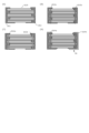
- FIG. 1 is a cross-sectional view showing an example (first embodiment) of a laminate.
- FIG. 2 is a cross-sectional view showing an example (first embodiment) of a power storage unit.
- FIG. 3 is a cross-sectional view showing an example (second embodiment) of the laminate.
- FIG. 4 is a cross-sectional view showing an example (second embodiment) of a power storage unit.
- FIG. 5 is a schematic diagram showing the procedure of the electrophoresis method (electrodeposition coating method).
- FIG. 6 is a schematic diagram showing the procedure of the bar coating method.
- FIG. 7 is an explanatory diagram showing the procedure for obtaining a laminate (first form) from an Al electrode/CNF sheet in an example.
- FIG. 8 is an explanatory diagram showing a procedure for obtaining a power storage unit (first embodiment) from a laminate in the example.
- FIG. 9 is an explanatory diagram showing the procedure for obtaining a laminate (second form) from a polymer electrode/CNF sheet in an example.
- FIG. 10 is an explanatory diagram showing a procedure for obtaining a power storage unit (second embodiment) from a laminate in the example.
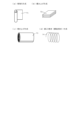
- FIG. 11 is a schematic diagram showing an example of the shape of the flexible laminate.
- the laminate includes a cellulose fiber layer and an electrode layer.
- the cellulose fiber layer is a layer containing cellulose fibers.
- the cellulose fiber layer generally contains cellulose fibers as a substantial main component, and the content of the cellulose fibers is, for example, 90% by mass or more, 95% by mass or more, 97% by mass or more, or 99% by mass or more, and preferably 100% by mass.
- components other than cellulose fibers that may be contained in the cellulose fiber layer include wood-derived components such as lignin and hemicellulose polysaccharides.
- the cellulose fibers are usually cellulose fibers derived from living organisms, and examples of such cellulose fibers include cellulose fibers derived from plants (e.g., wood, bamboo, hemp, jute, kenaf, rice), animals (e.g., ascidians), algae, microorganisms (e.g., acetic acid bacteria (Acetobacter)), microbial products, etc.
- the cellulose fibers are preferably cellulose fibers derived from plants or microorganisms, more preferably cellulose fibers derived from plants, especially wood.
- cellulose fibers derived from plants or microorganisms include pulp, powdered cellulose, crystalline cellulose, cellulose nanofibers, cellulose microfibrils, and regenerated cellulose, and the method and degree of processing are not particularly limited.
- pulp examples include chemical pulps such as kraft pulp (e.g., softwood kraft pulp such as softwood unbleached kraft pulp (NUKP) and softwood bleached kraft pulp (NBKP); hardwood kraft pulp such as hardwood unbleached kraft pulp (LUKP) and hardwood bleached kraft pulp (LBKP)), sulfite pulp (e.g., softwood sulfite pulp such as softwood unbleached sulfite pulp (NUSP) and softwood bleached sulfite pulp (NBSP)), mechanical pulp such as thermomechanical pulp (TMP), and regenerated pulp, and chemical pulp is preferred.
- chemical pulp such as kraft pulp (e.g., softwood kraft pulp such as softwood unbleached kraft pulp (NUKP) and softwood bleached kraft pulp (NBKP); hardwood kraft pulp such as hardwood unbleached kraft pulp (LUKP) and hardwood bleached kraft pulp (LBKP)), sulfite pulp (e
- the cellulose fiber may be cellulose fiber that has been subjected to a fine processing treatment, for example, cellulose nanofibers and cellulose microfibrils. Also, cellulose fiber obtained by a method of promoting fibrillation by enzymatically treating various pulps may be used. Furthermore, the cellulose fiber may be chemically modified cellulose fiber (e.g., pulp, cellulose nanofibers, cellulose microfibrils).
- the term "chemically modified cellulose fibers" refers to cellulose fibers that have been subjected to a chemical modification treatment. Chemically modified cellulose fibers and chemical modification treatments will be described later.
- the size of the cellulose fibers is not particularly limited, but examples are as follows:
- the number average fiber diameters of common softwood kraft pulp and hardwood kraft pulp are usually about 30 to 60 ⁇ m and about 10 to 30 ⁇ m, respectively.
- the number average fiber diameter of other pulps is usually about 50 ⁇ m. In the case of pulp refined from chips or the like that are several centimeters in size, it is preferable to adjust the number average fiber diameter to about 50 ⁇ m as necessary by a micronizing treatment described below.
- cellulose microfibrils refer to cellulose fibers having a fiber diameter of the micron order after being subjected to a pulverization treatment.
- the average fiber diameter of cellulose microfibrils is usually 500 nm or more, preferably 1 ⁇ m or more, and more preferably 10 ⁇ m or more. This allows the fibers to exhibit higher water retention than undefibrated cellulose fibers (e.g., pulp), and even a small amount of the fibers can provide higher strength and yield improvement effects than finely defibrated cellulose nanofibers.
- the upper limit of the average fiber diameter is preferably 40 ⁇ m or less, more preferably 30 ⁇ m or less, and even more preferably 20 ⁇ m or less, 18 ⁇ m or less, or 17 ⁇ m or less, but there is no particular limit.
- the average fiber length is preferably 10 ⁇ m or more or 20 ⁇ m or more, more preferably 30 ⁇ m or more, 40 ⁇ m or more, or 50 ⁇ m or more. There is no particular upper limit to the average fiber length, but it is preferably 1000 ⁇ m or less, more preferably 500 ⁇ m or less, more preferably 300 ⁇ m or less, and even more preferably 200 ⁇ m or less.
- the aspect ratio of the cellulose microfibrils is preferably 30 or more or 35 or more, more preferably 40 or more, even more preferably 50 or more, and even more preferably 60 or more. There is no particular upper limit to the aspect ratio, but it is preferably 1000 or less, more preferably 100 or less, and even more preferably 80 or less.
- cellulose nanofiber means cellulose fiber having a fiber diameter of nano-order after being subjected to a micronization process.
- the average fiber diameter (length-weighted average fiber diameter) of CNF is 500 nm or less, preferably 300 nm or less, more preferably 100 nm or less, and even more preferably 50 nm or less.
- the lower limit is not particularly limited, but is usually 1 nm or more, preferably 2 nm or more.
- the average fiber diameter (length-weighted average fiber diameter) of CNF is usually 1 to 500 nm or 2 to 500 nm, preferably 2 to 300 nm or 2 to 100 nm, more preferably 2 to 50 nm or 3 to 30 nm.
- the average fiber length (length-weighted average fiber length) is usually 50 to 2000 nm, preferably 100 to 1000 nm.
- the aspect ratio of CNF is usually 10 or more, preferably 50 or more.
- the upper limit is not particularly limited, but is usually 1000 or less.
- the average fiber diameter and average fiber length are determined by observing each fiber using an atomic force microscope (AFM) or a transmission electron microscope (TEM).
- the size of cellulose fibers can be adjusted by the conditions of micronization and chemical modification.
- Chemically modified cellulose fibers are obtained by chemically modifying unmodified cellulose fibers (e.g., unmodified pulp, unmodified powdered cellulose).
- Examples of chemical modification include cationization and anionization (carboxylation (oxidation), dicarboxylation, ozone oxidation, etherification (e.g., carboxymethylation), and esterification (phosphoric acid, phosphorous acid, sulfuric acid)).
- Anionization is preferred, and carboxylation and etherification are more preferred.
- chemical modification e.g., oxidation
- the cellulose fibers become a solid electrolyte and an electric double layer is formed, so that they can be expected to be used as a supercapacitor.
- the chemical modification is usually performed before or after the microparticulation treatment, and is preferably performed before the microparticulation treatment.
- Carboxylated cellulose fibers (oxidized cellulose fibers) usually have a structure in which at least one of the carbon atoms having a primary hydroxyl group contained in the glucopyranose unit constituting the cellulose molecular chain (for example, the carbon atom having a primary hydroxyl group at the C6 position) is oxidized.
- the amount of carboxyl groups in the carboxylated cellulose fibers is preferably 0.6 to 3.0 mmol/g, and more preferably 1.0 to 2.0 mmol/g.
- the amount of carboxyl groups can be adjusted by controlling the conditions for carboxylating the cellulose fibers (for example, the amount of oxidizing agent added, the reaction time).
- Carboxylated cellulose fibers can be produced by carboxylating (oxidizing) unmodified cellulose fibers (cellulose raw material: for example, pulp).
- carboxylation (oxidation) method is a method in which the cellulose raw material is oxidized in water using an oxidizing agent in the presence of an N-oxyl compound and a compound selected from the group consisting of bromides, iodides, or mixtures thereof.
- This oxidation reaction selectively oxidizes the carbon atom having a primary hydroxyl group at the C6 position of the glucopyranose ring on the cellulose surface, thereby obtaining chemically modified cellulose having an aldehyde group and a carboxyl group (-COOH) or a carboxylate group ( -COO- ) on the surface.
- concentration of the cellulose raw material during the reaction is not particularly limited, but is preferably 5% by mass or less.
- N-oxyl compound is a compound that can generate nitroxy radicals. Any compound that promotes the desired oxidation reaction can be used as an N-oxyl compound. Examples include 2,2,6,6-tetramethylpiperidine-1-oxy radical (TEMPO) and its derivatives (e.g., 4-hydroxyTEMPO).
- TEMPO 2,2,6,6-tetramethylpiperidine-1-oxy radical
- 4-hydroxyTEMPO 4-hydroxyTEMPO
- the amount of N-oxyl compound used is not particularly limited, as long as it is a catalytic amount capable of oxidizing the cellulose raw material.
- a catalytic amount capable of oxidizing the cellulose raw material for 1 g of bone-dry cellulose raw material, 0.01 to 10 mmol is preferred, 0.01 to 1 mmol is more preferred, and 0.05 to 0.5 mmol is even more preferred.
- the amount is preferably about 0.1 to 4 mmol/L of the reaction system.
- Bromides are compounds that contain bromine, such as bromides of alkali metals that can dissociate and ionize in water.
- Iodides are compounds that contain iodine, such as iodides of alkali metals.
- the amount of bromide or iodide used can be selected within a range that can promote the oxidation reaction.
- the total amount of bromide and iodide is, for example, preferably 0.1 to 100 mmol, more preferably 0.1 to 10 mmol, and even more preferably 0.5 to 5 mmol, per 1 g of bone-dry cellulose raw material.
- oxidizing agent such as halogens, hypohalous acids, hypohalous acids, perhalogen acids or their salts, halogen oxides, and peroxides.
- sodium hypochlorite is preferred, as it is inexpensive and has a low environmental impact.
- the appropriate amount of oxidizing agent to be used is, for example, preferably 0.5 to 500 mmol, more preferably 0.5 to 50 mmol, even more preferably 1 to 25 mmol, and even more preferably 3 to 10 mmol, per 1 g of bone-dry cellulose raw material.
- 1 to 40 mol is preferred per 1 mol of N-oxyl compound.
- the reaction temperature is preferably 4 to 40°C, or may be room temperature of around 15 to 30°C.
- carboxyl groups are generated in the cellulose, causing a decrease in the pH of the reaction solution.
- an alkaline solution such as an aqueous sodium hydroxide solution to maintain the pH of the reaction solution at 8 to 12, preferably 10 to 11. Water is preferred as the reaction medium, as it is easy to handle and unlikely to cause side reactions.
- the reaction time for the oxidation reaction can be set appropriately according to the degree of progress of the oxidation, and is usually about 0.5 to 6 hours, for example, about 0.5 to 4 hours.
- the oxidation reaction may be carried out in two stages.
- the oxidized cellulose obtained by filtration after the completion of the first stage reaction can be oxidized again under the same or different reaction conditions, allowing efficient oxidation without reaction inhibition by table salt, which is a by-product of the first stage reaction.
- Another example of the carboxylation (oxidation) method is a method of contacting a gas containing ozone with a cellulose raw material to oxidize it.
- This oxidation reaction oxidizes at least the hydroxyl groups at the 2- and 6-positions of the glucopyranose ring, and decomposes the cellulose chain.
- the ozone concentration in the gas containing ozone is preferably 50 to 250 g/m 3 , more preferably 50 to 220 g/m 3.
- the amount of ozone added to the cellulose raw material is preferably 0.1 to 30 parts by mass, more preferably 5 to 30 parts by mass, when the solid content of the cellulose raw material is 100 parts by mass.
- the ozone treatment temperature is preferably 0 to 50°C, more preferably 20 to 50°C.
- the ozone treatment time is not particularly limited, but is about 1 to 360 minutes, and preferably about 30 to 360 minutes. When the ozone treatment conditions are within these ranges, it is possible to prevent the cellulose raw material from being excessively oxidized and decomposed, and the yield of oxidized cellulose is good.
- a further oxidation treatment may be carried out using an oxidizing agent.
- the oxidizing agent used in the further oxidation treatment is not particularly limited, but examples include chlorine compounds such as chlorine dioxide and sodium chlorite, oxygen, hydrogen peroxide, persulfuric acid, and peracetic acid.
- these oxidizing agents can be dissolved in water or a polar organic solvent such as alcohol to prepare an oxidizing agent solution, and the further oxidation treatment can be carried out by immersing the oxidized cellulose in the solution.
- Salt-type oxidized cellulose usually has mainly salt-type carboxyl groups ( -COO- ).
- Examples of counter cations of salt-type carboxyl groups include alkali metals such as Li, Na, and K; alkaline earth metals such as Mg and Ca; Fe; and metals such as Al, with Li, Na, K, and Ca being preferred, Na, K, and Ca being more preferred, and Na being even more preferred.
- the salt-type carboxyl group has a counter cation
- the cation binds with bound water, thereby making it possible to further increase the electricity storage efficiency, and it is expected that the electricity storage characteristics can be maintained even at high temperatures (e.g., 100°C or higher), thereby compensating for the decrease in electricity storage performance at high temperatures, which is a drawback of conventional artificial electricity storage bodies.
- the counter cation is Na in oxidized cellulose obtained by a normal oxidation method
- methods for replacing Na with a desired metal include, for example, a treatment in which the cation is brought into contact with a compound having the desired metal (e.g., a hydroxide) after a desalting treatment, and an ion exchange treatment using a compound having the desired metal (e.g., a chloride).
- a treatment in which the cation is brought into contact with a compound having the desired metal (e.g., a hydroxide) after a desalting treatment e.g., a hydroxide
- an ion exchange treatment using a compound having the desired metal e.g., a chloride
- Oxidized cellulose contains carboxyl groups as a result of oxidation, but it may contain more acid-type carboxyl groups (-COOH) than salt-type carboxyl groups ( -COO- ), or it may contain more salt-type carboxyl groups than acid-type carboxyl groups.
- the amount of salt-type carboxyl groups and acid-type carboxyl groups can be adjusted by desalting treatment. By desalting treatment, salt-type carboxyl groups can be converted to acid-type carboxyl groups.
- oxidized cellulose (which has been desalted) is called acid-type oxidized cellulose, and oxidized cellulose (which has not been desalted, as described below) is called salt-type oxidized cellulose.
- Salt-type oxidized cellulose usually contains mainly salt-type carboxyl groups (-COO-).
- acid-type oxidized cellulose contains many acid-type carboxyl groups, and the proportion of acid-type carboxyl groups in the carboxyl groups is preferably 40% or more, more preferably 60% or more, and even more preferably 85% or more.
- the proportion of acid-type carboxyl groups can be calculated by the following procedure.
- the timing of desalting may be after oxidation, and may be either before or after defibration (before or after step (2)), but is usually after oxidation, and preferably before step (2).
- Desalting is usually carried out by substituting salts (e.g., sodium salts) contained in the salt-type oxidized cellulose with protons.
- Examples of desalting methods include a method of adjusting the system to be acidic, and a method of contacting oxidized cellulose with a cation exchange resin.
- the pH of the system is preferably adjusted to 2 to 6, more preferably 2 to 5, and even more preferably 2.3 to 5.
- an acid e.g., inorganic acids such as sulfuric acid, hydrochloric acid, nitric acid, sulfurous acid, nitrous acid, and phosphoric acid; organic acids such as acetic acid, lactic acid, oxalic acid, citric acid, and formic acid
- a washing treatment may be carried out as appropriate.
- the cation exchange resin either a strongly acidic ion exchange resin or a weakly acidic ion exchange resin can be used as long as the counter ion is H + .
- the ratio of the oxidized cellulose and the cation exchange resin when they are contacted is not particularly limited, and a person skilled in the art can set it appropriately from the viewpoint of efficient proton replacement.
- the cation exchange resin after contact can be recovered by a conventional method such as suction filtration.
- etherification examples include etherification by a reaction selected from carboxyalkylation, methylation, ethylation, cyanoethylation, hydroxyethylation, hydroxypropylation, ethylhydroxyethylation, and hydroxypropylmethylation, with carboxyalkylation being preferred and carboxymethylation being more preferred.
- Carboxyalkylated cellulose fibers usually have a structure in which at least one of the carbon atoms constituting the cellulose molecular chain (for example, the carbon atom bearing a primary hydroxyl group at the C6 position constituting the glucopyranose unit) is carboxymethylated.
- the degree of carboxyalkyl substitution (DS, preferably the degree of carboxymethyl substitution) per anhydrous glucose unit of the carboxyalkylated cellulose is preferably 0.01 or more, 0.02 or more, or 0.05 or more, more preferably 0.10 or more, even more preferably 0.15 or more, even more preferably 0.20 or more, and particularly preferably 0.25 or more. This ensures a degree of substitution that can achieve the effects of chemical modification.
- the upper limit of the degree of substitution is preferably 0.50 or less, more preferably 0.45 or less, 0.40 or less, or 0.35 or less. This makes it difficult for the cellulose fibers to dissolve in water, and allows the fiber form to be maintained in water. Therefore, the degree of carboxyalkyl substitution is preferably 0.01 to 0.50, more preferably 0.01 to 0.45, even more preferably 0.02 to 0.40, 0.10 to 0.35, or 0.20 to 0.30.
- the degree of substitution for example, the degree of carboxymethyl substitution, can be measured by the following method. Approximately 2.0 g of carboxymethylated cellulose (bone dry) is weighed out and placed in a 300 mL Erlenmeyer flask with a stopper. 100 mL of a solution obtained by adding 100 mL of special-grade concentrated nitric acid to 1,000 mL of methanol is added, and the mixture is shaken for 3 hours to convert the salt-type carboxymethylated cellulose (hereinafter also referred to as "salt-type carboxymethylated cellulose") to the acid-type carboxymethylated cellulose (hereinafter also referred to as "acid-type carboxymethylated cellulose").
- salt-type carboxymethylated cellulose hereinafter also referred to as "salt-type carboxymethylated cellulose”
- F' Factor of 0.1N H2SO4
- F Factor of 0.1N NaOH
- the degree of carboxyalkyl substitution can be adjusted by controlling the reaction conditions, such as the amount of carboxyalkylating agent added to the reaction, the amount of mercerizing agent, and the composition ratio of water and organic solvent.
- carboxyalkylation method is to mercerize the cellulosic raw material as the starting material (bottom raw material) and then etherify it. Carboxymethylation will be explained below as an example.
- Carboxymethylated cellulose can be produced by starting with unmodified cellulose fibers (cellulose raw material: e.g., pulp) and carrying out a mercerization treatment in the presence of 3 to 20 times the mass of the solvent, followed by an etherification reaction.
- the solvent for example, water or a lower alcohol (e.g., methanol, ethanol, n-propyl alcohol, isopropyl alcohol, n-butyl alcohol, isobutyl alcohol, tertiary butanol) can be used alone or in a mixture of two or more kinds.
- a lower alcohol e.g., methanol, ethanol, n-propyl alcohol, isopropyl alcohol, n-butyl alcohol, isobutyl alcohol, tertiary butanol
- the mixing ratio of the lower alcohol is preferably 60 to 95% by mass.
- an alkali metal hydroxide e.g., sodium hydroxide, potassium hydroxide
- an alkali metal hydroxide e.g., sodium hydroxide, potassium hydroxide
- the starting material, solvent, and mercerizing agent are mixed, and a mercerization treatment is carried out at a reaction temperature of 0 to 70°C, preferably 10 to 60°C, for a reaction time of 15 minutes to 8 hours, preferably 30 minutes to 7 hours.
- a carboxymethylating agent e.g., sodium monochloroacetate
- carboxymethylated cellulose can be produced by carrying out an etherification reaction at a reaction temperature of 30 to 90°C, preferably 40 to 80°C, for a reaction time of 30 minutes to 10 hours, preferably 1 hour to 4 hours.
- the carboxyalkylated cellulose fiber maintains at least a part of its fibrous shape even when dispersed in water.
- the carboxyalkylated cellulose fiber is distinguished from cellulose powder such as carboxymethyl cellulose, which is a type of water-soluble polymer that dissolves in water and imparts viscosity.
- carboxymethyl cellulose which is a type of water-soluble polymer that dissolves in water and imparts viscosity.
- anion-modified cellulose fiber is measured by X-ray diffraction, a peak of cellulose type I crystals can be observed, but when carboxymethyl cellulose powder, which is a water-soluble polymer, is similarly measured, cellulose type I crystals are usually not observed.
- Carboxyalkylated cellulose may contain more acid-type carboxyl groups than salt-type carboxyl groups, or may contain more salt-type carboxyl groups than acid-type carboxyl groups.
- the amount of salt-type carboxyl groups and acid-type carboxyl groups can be adjusted by desalting treatment. By desalting treatment, salt-type carboxyl groups can be converted to acid-type carboxyl groups.
- carboxyalkylated cellulose (which has been desalted) is called acid-type carboxyalkylated cellulose
- carboxyalkylated cellulose (which has not been desalted, as described below) is called salt-type carboxyalkylated cellulose.
- Salt-type carboxyalkylated cellulose usually mainly has salt-type carboxyl groups (-COO-).
- acid-type carboxyalkylated cellulose has many acid-type carboxyl groups, and the ratio of the amount of acid-type carboxyl groups to the amount of carboxyl groups in the acid-type carboxyalkylated cellulose is preferably 40% or more, more preferably 60% or more, and even more preferably 85% or more.
- the method for calculating the ratio of acid-type carboxyl groups is as described above.
- the timing of desalting is usually after carboxyalkylation, preferably after etherification and before fibrillation.
- the desalting method may be a method of contacting carboxyalkylated cellulose with a cation exchange resin.
- the cation exchange resin either a strong acid ion exchange resin or a weak acid ion exchange resin can be used as long as the counter ion is H + .
- the ratio of the two when contacting carboxyalkylated cellulose with a cation exchange resin is not particularly limited, and a person skilled in the art can appropriately set it from the viewpoint of efficient proton replacement.
- the ratio can be adjusted so that the pH of the aqueous dispersion after addition of the cation exchange resin is preferably 2 to 6, more preferably 2 to 5, relative to the carboxyalkylated cellulose aqueous dispersion.
- the cation exchange resin after contact may be recovered by a conventional method such as suction filtration.
- a first example of an esterified cellulose fiber is phosphorylated cellulose, which usually has a structure in which at least one of the carbon atoms constituting the cellulose molecular chain (for example, the carbon atom having a primary hydroxyl group at the C6 position constituting the glucopyranose unit) is phosphorylated.
- the amount of ionic substituent introduced into the phosphorylated cellulose fiber may be 0.10 mmol/g or more per 1 g (mass) of phosphorylated CNF, preferably 0.20 mmol/g or more, more preferably 0.30 mmol/g or more, even more preferably 0.40 mmol/g or more, even more preferably 0.50 mmol/g or more, even more preferably 0.60 mmol/g or more, and particularly preferably 0.70 mmol/g or more.
- the amount of ionic substituent introduced into the phosphorylated CNF may be 1.50 mmol/g or less per 1 g (mass) of cellulose fiber, preferably 1.35 mmol/g or less, more preferably 1.20 mmol/g or less, and even more preferably 1.10 mmol/g or less.
- the amount of ionic substituent introduced into the phosphorylated cellulose fiber may be 1.00 mmol/g or less per 1 g (mass) of phosphorylated cellulose fiber, more preferably 0.95 mmol/g or less.
- the denominator in the unit mmol/g indicates the mass of the cellulose fiber when the counter ion of the ionic substituent is a hydrogen ion (H + ).
- the amount of phosphorus oxo acid substituent can be measured by the following method.
- the amount of phosphorus oxoacid groups in the fine cellulose fibers can be measured by diluting a fine cellulose fiber dispersion containing the target fine cellulose fibers with ion exchange water to a content of 0.2 mass% to prepare a cellulose fiber-containing slurry, treating the slurry with an ion exchange resin, and then titrating the slurry with an alkali.
- the treatment with ion exchange resin was carried out by adding 1/10 by volume of a strongly acidic ion exchange resin (Amberjet 1024; Organo Corporation, conditioned) to the cellulose fiber-containing slurry, shaking for 1 hour, and then pouring the mixture onto a mesh with 90 ⁇ m openings to separate the resin from the slurry.
- a strongly acidic ion exchange resin Amberjet 1024; Organo Corporation, conditioned
- the titration using alkali was performed by measuring the change in the pH value of the slurry while adding 10 ⁇ L of 0.1N sodium hydroxide aqueous solution to the cellulose fiber-containing slurry after the treatment with the ion exchange resin every 5 seconds. The titration was performed while blowing nitrogen gas into the slurry 15 minutes before the start of the titration. In this neutralization titration, two points are observed where the increment (differential value of pH with respect to the amount of alkali dropped) is maximum on a curve plotting the measured pH against the amount of alkali added.
- the maximum point of the increment obtained first after the addition of alkali is called the first end point, and the maximum point of the increment obtained next is called the second end point.
- the amount of alkali required from the start of the titration to the first end point is equal to the amount of first dissociated acid in the slurry used for the titration.
- the amount of alkali required from the start of the titration to the second end point is equal to the total amount of dissociated acid in the slurry used for the titration.
- the amount of phosphorus oxoacid group was determined by dividing the amount of alkali (mmol) required from the start of titration to the first end point by the solid content (g) in the slurry to be titrated.
- the introduction of phosphate group may be confirmed by measuring infrared absorption spectrum to confirm absorption due to phosphate group (near 1230 cm -1 ).
- the amount of phosphate groups can be adjusted by controlling the reaction conditions, such as the amount of compound containing phosphate groups added and the amount of basic compound added if necessary.
- An example of a phosphorylation method is to react a compound having a phosphoric acid group with unmodified cellulose fibers (phosphorylation).
- Examples of phosphorylation methods include mixing a powder or an aqueous solution of a compound having a phosphoric acid group with a cellulose-based raw material, and adding an aqueous solution of a compound having a phosphoric acid group to an aqueous dispersion of the cellulose-based raw material, with the latter being preferred. This can increase the uniformity of the reaction and improve the efficiency of esterification.
- Examples of compounds having a phosphate group include phosphoric acid, sodium dihydrogen phosphate, disodium hydrogen phosphate, trisodium phosphate, sodium pyrophosphate, sodium metaphosphate, potassium dihydrogen phosphate, dipotassium hydrogen phosphate, tripotassium phosphate, potassium pyrophosphate, potassium metaphosphate, ammonium dihydrogen phosphate, diammonium hydrogen phosphate, triammonium phosphate, ammonium pyrophosphate, and ammonium metaphosphate.
- Compounds having a phosphate group can be used alone or in combination of two or more.
- the amount of the compound having a phosphate group added to the cellulose raw material is preferably 0.1 to 500 parts by mass, more preferably 1 to 400 parts by mass, and even more preferably 2 to 200 parts by mass, in terms of phosphorus element, per 100 parts by mass of the solid content of the cellulose raw material.
- the reaction temperature is preferably 0 to 95°C, more preferably 30 to 90°C.
- the reaction time is not particularly limited, but is usually about 1 to 600 minutes, and preferably 30 to 480 minutes. When the conditions of the esterification reaction are within any of these ranges, it is possible to prevent cellulose from being excessively esterified and becoming easily dissolved, and the yield of phosphorylated cellulose can be improved.
- a basic compound e.g., a compound having an amino group that exhibits basicity, such as urea, methylamine, ethylamine, trimethylamine, triethylamine, monoethanolamine, diethanolamine, triethanolamine, pyridine, ethylenediamine, or hexamethylenediamine
- a basic compound e.g., a compound having an amino group that exhibits basicity, such as urea, methylamine, ethylamine, trimethylamine, triethylamine, monoethanolamine, diethanolamine, triethanolamine, pyridine, ethylenediamine, or hexamethylenediamine
- a second example of a method for producing an esterified cellulose fiber is a phosphite-esterified cellulose fiber.
- Phosphite-esterified cellulose fiber usually has a structure in which at least one of the carbon atoms constituting the cellulose molecular chain (for example, the carbon atom having a primary hydroxyl group at the C6 position constituting the glucopyranose unit) is phosphorylated.
- the degree of substitution of the phosphite group per glucose unit in the phosphite esterified cellulose fiber (hereinafter simply referred to as the "degree of substitution of the phosphite group”) is preferably 0.001 or more and less than 0.40.
- the degree of substitution of the phosphite group can be measured by the same method as that for measuring the degree of substitution of the phosphate group.
- the degree of substitution of the phosphite group can be adjusted by controlling reaction conditions such as the amount of phosphorous acid or a salt thereof added, the amount of an alkali metal ion-containing material used as necessary, and the amount of urea or a derivative thereof added.
- An example of a method for phosphite esterification is to react unmodified cellulose fibers with phosphorous acid or a metal salt thereof (preferably sodium hydrogen phosphite) to introduce an ester group of phosphorous acid.
- phosphorous acid or a metal salt thereof preferably sodium hydrogen phosphite
- Examples of phosphorous acid and its metal salts include phosphorous acid compounds such as phosphorous acid, sodium hydrogen phosphite, ammonium hydrogen phosphite, potassium hydrogen phosphite, sodium dihydrogen phosphite, sodium phosphite, lithium phosphite, potassium phosphite, magnesium phosphite, calcium phosphite, triethyl phosphite, triphenyl phosphite, and pyrophosphorous acid, and combinations of two or more selected from these, with sodium hydrogen phosphite being preferred. This allows alkali metal ions to be introduced into the cellulose fibers.
- phosphorous acid compounds such as phosphorous acid, sodium hydrogen phosphite, ammonium hydrogen phosphite, potassium hydrogen phosphite, sodium dihydrogen phosphite, sodium phosphite, lithium phosphite, potassium phosphite, magnesium
- the amount of phosphorous acid or its metal salts added is preferably 1 to 10,000 g, more preferably 100 to 5,000 g, and even more preferably 300 to 1,500 g per kg of unmodified cellulose fibers.
- an alkali metal ion-containing material e.g., hydroxide, metal sulfate, metal nitrate, metal chloride, metal phosphate, metal carbonate
- hydroxide, metal sulfate, metal nitrate, metal chloride, metal phosphate, metal carbonate may be further added to the reaction system.
- Urea or a derivative thereof may also be added to the reaction system. This allows carbamate groups to also be introduced into the cellulose fibers.
- urea and urea derivatives include urea, thiourea, biuret, phenylurea, benzylurea, dimethylurea, diethylurea, tetramethylurea, and combinations of two or more selected from these, with urea being preferred.
- the amount of urea and urea derivatives added is preferably 0.01 to 100 mol, more preferably 0.2 to 20 mol, and even more preferably 0.5 to 10 mol per mol of phosphorous acid or its metal salt.
- the reaction temperature is preferably 100 to 200°C, more preferably 100 to 180°C.
- the reaction time is usually about 10 to 180 minutes, more preferably 30 to 120 minutes.
- the phosphite esterified cellulose fibers are preferably washed prior to defibration.
- the degree of substitution of phosphite groups per glucose unit is preferably 0.01 or more and less than 0.23.
- a third example of the method for producing an esterified cellulose fiber is a sulfated cellulose fiber.
- Cellulose sulfate usually has a structure in which at least one of the carbon atoms constituting the cellulose molecular chain (for example, the carbon atom having a primary hydroxyl group at the C6 position constituting the glucopyranose unit) is phosphorylated.
- the amount of sulfate groups per glucose unit in sulfated cellulose fibers is preferably 0.1 to 3.0 mmol/g.
- the degree of cationic substitution per glucose unit is 0.50 or less, swelling or dissolution can be suppressed, and a situation in which it becomes impossible to obtain nanofibers can be prevented.
- the amount of sulfate groups per glucose unit can be measured by the following method.
- An aqueous dispersion of sulfated CNF is subjected to solvent replacement with ethanol and then t-butanol, and then freeze-dried.
- 15 ml of ethanol and 5 ml of water are added to 200 mg of the obtained sample, and the mixture is stirred for 30 minutes.
- 10 ml of 0.5 N aqueous sodium hydroxide solution is added, and the mixture is stirred at 70°C for 30 minutes and further stirred at 30°C for 24 hours.
- Amount of sulfate group [mmol/g sample] (5-(0.1 ⁇ titer of hydrochloric acid [ml] ⁇ 2))/0.2.
- the amount of sulfate groups can be adjusted by controlling the reaction conditions, such as the amount of sulfate compound added to the reaction.
- One example of a method for sulfate esterification is to react unmodified cellulose fibers with a sulfate compound to introduce sulfate groups derived from the sulfate compound into the cellulose to produce sulfated cellulose.
- sulfate compounds include sulfuric acid, sulfamic acid, chlorosulfonic acid, sulfur trioxide, and esters or salts of these. Of these, it is preferable to use sulfamic acid, since it has low solubility in cellulose and low acidity.
- the amount of sulfamic acid used can be adjusted appropriately taking into account the amount of anion groups introduced into the cellulose chain.
- the amount is preferably 0.01 to 50 mol, more preferably 0.1 to 3.0 mol, per 1 mol of glucose units in the cellulose molecule.
- Esterified cellulose may contain more acid type carboxyl groups than salt type carboxyl groups, or may contain more salt type carboxyl groups than acid type carboxyl groups.
- esterified cellulose those that have not been subjected to desalting treatment and those that have been subjected to desalting treatment are called salt type esterified cellulose and acid type esterified cellulose, respectively.
- Salt type esterified cellulose mainly has salt type carboxyl groups. The counter cations of the salt type carboxyl groups and the preparation method thereof are as explained in the explanation of oxidized cellulose.
- Cationic cellulose usually has a structure in which at least one of the carbon atoms constituting the cellulose molecular chain (for example, the carbon atom having a primary hydroxyl group at C6 constituting the glucopyranose unit) is cationized.
- the degree of cationic substitution per glucose unit in cationized cellulose is preferably 0.02 to 0.50.
- the degree of cationic substitution per glucose unit can be measured by the following method.
- the degree of cationic substitution can be adjusted by changing reaction conditions such as the amount of cationizing agent added to the reaction and the composition ratio of water or alcohol with 1 to 4 carbon atoms.
- An example of a method for cationization is to react unmodified cellulose fibers with a cationization agent (e.g., glycidyl trimethylammonium chloride, 3-chloro-2-hydroxypropyl trialkylammonium hydride or its halohydrin form) and an alkali metal hydroxide catalyst (e.g., sodium hydroxide, potassium hydroxide) in the presence of water and/or an alcohol having 1 to 4 carbon atoms.
- a cationization agent e.g., glycidyl trimethylammonium chloride, 3-chloro-2-hydroxypropyl trialkylammonium hydride or its halohydrin form
- an alkali metal hydroxide catalyst e.g., sodium hydroxide, potassium hydroxide
- the cationized cellulose fibers after cationization are preferably converted to base-type cationized cellulose or base-type cationized cellulose nanofibers by desalting.
- the salt in the cationized cellulose can be converted to a base by desalting.
- cationized cellulose (nanofibers) that have been desalted are referred to as base-type cationized cellulose (nanofibers) or cationized cellulose (nanofibers) (base type).
- Desalting may be performed at any time before (cationized cellulose) or after (cationized cellulose nanofibers) defibration, which will be described later. Desalting means that the salt (e.g. Cl - ) contained in the cationized cellulose (salt type) and the cationized cellulose nanofiber (salt type) is replaced with a base to make it a base type.
- a method of contacting the cationized cellulose or the cationized cellulose nanofibers with an anion exchange resin can be mentioned.
- the anion exchange resin either a strong basic ion exchange resin or a weak basic ion exchange resin can be used as long as the counter ion is OH- .
- the ratio of the two when the modified cellulose is contacted with the anion exchange resin is not particularly limited, and a person skilled in the art can set it appropriately from the viewpoint of efficient cationic replacement.
- the ratio can be adjusted so that the pH of the aqueous dispersion after addition of the anion exchange resin to the cationized cellulose nanofiber aqueous dispersion is preferably 8 to 13, more preferably 9 to 13.
- the anion exchange resin after contact can be recovered by a conventional method such as suction filtration. (Micronization (defibration, fibrillation))
- the pulverization is usually carried out by mechanical treatment.
- the mechanical treatment (preferably beating or disintegration) is usually carried out wet (i.e. in the form of an aqueous dispersion of cellulose fibers).
- Apparatuses used for mechanical treatment include, for example, refining equipment (refiners; e.g., disk type, conical type, cylinder type), high-speed fiberizers, shear-type agitators, colloid mills, high-pressure jet dispersers, beaters, PFI mills, kneaders, dispersers, high-speed disintegrators (top finers), high-pressure or ultra-high-pressure homogenizers, grinders (stone-type grinders), ball mills, vibration mills, bead mills, single-axis, twin-axis or multi-axis kneaders/extruders, homomixers under high-speed rotation, refining equipment, etc.
- Examples of such a device include a device that can apply a mechanical defibration force, such as a refiner, defibrator, friction grinder, high-share defibrator, disperger, or homogenizer (e.g., microfluidizer), and devices that can apply a wet defibration force are preferred, and high-speed disintegrators and refining devices are more preferred, but are not particularly limited.
- a mechanical defibration force such as a refiner, defibrator, friction grinder, high-share defibrator, disperger, or homogenizer (e.g., microfluidizer)
- homogenizer e.g., microfluidizer
- an aqueous dispersion of cellulose fibers is usually prepared.
- the solids concentration of the modified cellulose in the aqueous dispersion is preferably 0.1% by mass or more, more preferably 0.5% by mass or more, even more preferably 1.0% by mass or more, and even more preferably 1.5% by mass or more.
- the upper limit of the concentration is preferably 15% by mass or less, more preferably 10% by mass or less, and even more preferably 8% by mass or less.
- pH adjustment e.g., 7 or less, 6 or less, 5 or less
- a pretreatment such as dry grinding (e.g., grinding after drying) may be performed prior to preparing the aqueous dispersion.
- a pretreatment such as dry grinding (e.g., grinding after drying)
- the apparatus used for dry grinding include, but are not limited to, impact mills such as hammer mills and pin mills, media mills such as ball mills and tower mills, and jet mills.
- a posttreatment may be performed after defibration.
- posttreatment examples include, but are not limited to, drying (e.g., freeze drying, spray drying, tray drying, drum drying, belt drying, thin spreading on a glass plate or the like and drying, fluidized bed drying, microwave drying, heated fan reduced pressure drying, reduced pressure (degassing) drying), redispersion in water (dispersion apparatus is not limited), and grinding (e.g., grinding using equipment such as a cutter mill, hammer mill, pin mill, or jet mill).
- drying e.g., freeze drying, spray drying, tray drying, drum drying, belt drying, thin spreading on a glass plate or the like and drying, fluidized bed drying, microwave drying, heated fan reduced pressure drying, reduced pressure (degassing) drying), redispersion in water (dispersion apparatus is not limited
- grinding e.g., grinding using equipment such as a cutter mill, hammer mill, pin mill, or jet mill.
- the cellulose fibers preferably have a specific surface area of 10 m 2 /g or more, more preferably 100 m 2 /g or more, and even more preferably 300 m 2 /g or more, which allows electricity to be stored for a shorter period of time and enables large-capacity electricity storage.
- the specific surface area can be measured by the following steps (1) to (9) with reference to the nitrogen gas adsorption method (JIS Z8830).
- the mixture in the container is stirred at 3,000 rpm for 30 minutes using a Homo Disper 2.5 model (Primix Corporation).
- the cellulose fibers are precipitated in a centrifuge at 7,000 G for 30 minutes at 30° C.
- the supernatant is removed so as to remove as little of the settled cellulose fibers as possible.
- the cellulose fiber preferably has a crystalline portion, and more preferably has a crystalline portion inside the fiber layer. This allows a uniform uneven portion to be formed on the surface of the cellulose fiber layer, thereby increasing the amount of stored electricity.
- the crystalline portion may be single crystal or polycrystalline, and the ratio of the polycrystalline portion is preferably 10 vol% or less of the cellulose fiber layer.
- the cellulose fiber preferably has an amorphous portion, and more preferably has an amorphous surface (e.g., a surface in contact with an electrode).
- This allows for charge storage.
- the flexibility of the bond (C5-C6 bond) between the carbon atom at the C5 position and the carbon atom at the C6 position of the glucopyranose unit constituting the cellulose fiber allows for rotation of the anion group (e.g., C6 carboxyl group) at the C6 position, resulting in high charge storage.
- the presence or absence of an amorphous portion can be confirmed by whether or not a broad peak is generated by X-ray analysis, or whether or not a halo pattern is generated by electron beam analysis.
- Cellulose fibers preferably have atomic vacancies.
- the presence of atomic vacancies allows protons to be electrically charged, forming an electric double layer, which can serve as a storage battery.
- Atomic vacancies are an inherent characteristic of amorphous materials. The size and amount of atomic vacancies can be confirmed by positron annihilation spectroscopy.
- the cellulose fiber layer may contain one type of cellulose fiber or a combination of two or more types of cellulose fibers.
- the cellulose fiber layer may contain components other than cellulose fibers.
- the thickness of the cellulose fiber layer is usually 100 ⁇ m or less, 50 ⁇ m or less, 40 ⁇ m or less, 30 ⁇ m or less, or 20 ⁇ m or less, preferably 10 ⁇ m or less or 5 ⁇ m or less, more preferably 3 ⁇ m or less, 2 ⁇ m or less, or 1 ⁇ m or less.
- This allows the device to be lightweight even in the case of a multi-layer laminate.
- static electricity is attached and detached on the surface, by making it into a thin film, the power density and energy density can be increased.
- the electrode layer is a layer containing an electrode material.
- the electrode material include metal electrode materials and polymer electrode materials.
- the metal electrode material include carbon (C), aluminum (Al), copper (Cu), gold (Au), silver (Ag), molybdenum (Mo), chromium (Cr), iron (Fe), zinc (Zn), titanium (Ti), nickel (Ni), lead (Pb), platinum (Pt), tungsten (W), bismuth (Bi), cobalt (Co), silicon wafer (SiO 2 ), Ag alloy, Al alloy, Mo alloy, Fe alloy (e.g., stainless steel), and other metals, and metal oxides such as ZnO.
- the polymer electrode material examples include conductive resins such as polyacetylene, polythiophene, polyethylenedioxythiophene, polyacene, polyaniline, polypyrrole, polyphenylenevinylene, polyamine, polyferrocene, and polyphthalocyanine.
- conductive resins such as polyacetylene, polythiophene, polyethylenedioxythiophene, polyacene, polyaniline, polypyrrole, polyphenylenevinylene, polyamine, polyferrocene, and polyphthalocyanine.
- Al and Cr are preferred in terms of good electrical conductivity, low specific gravity, economic efficiency, good corrosion resistance, and ease of bonding to cellulose materials.
- polythiophene and polyethylenedioxythiophene are preferred in terms of good electrical conductivity, low specific gravity, and thin film properties.
- Each electrode layer may be a layer made of the same electrode material or may be a layer made of different electrode materials.
- the thickness of the electrode layer is usually 0.01 ⁇ m to 500 ⁇ m, preferably 1 ⁇ m to 100 ⁇ m.
- the laminate may generally contain layers other than the cellulose fiber layer and the electrode layer, such as an adhesive layer and a substrate.
- the adhesive layer is a layer located between the cellulose fiber layer and the electrode layer and serves to bond the two together.
- the adhesive layer is made of a component having electrical conductivity (e.g., carbon).
- the adhesive layer may be made of, for example, an electrically conductive double-sided tape.
- the thickness of the adhesive layer is usually 300 ⁇ m or less, preferably 150 ⁇ m or less.
- the substrate is usually provided in contact with the electrode layer (the outermost electrode layer when two or more electrode layers are used).
- substrate materials include organic materials such as plastics, and inorganic materials such as silicon and glass.
- the laminate has a plurality of electrode layers and cellulose fiber layers, and the layers are alternately stacked in parallel when viewed from the thickness direction.
- the electrode layers and the cellulose fiber layers are bonded to each other, but the ends of the electrode layers are alternately protruding when viewed from the vertical direction. Therefore, the laminate has a so-called comb-shaped structure in which the electrode layers are sandwiched between a pair of cellulose fiber layers and have an uneven shape. This eliminates the need to move the electric wire back and forth when joining the electrode layers in the electricity storage unit, and the occurrence of gaps and breaks between the electrode layers can be suppressed, making it possible to manufacture an electricity storage unit with a dense structure and high electricity storage capacity and stability.
- the laminate can be changed in shape by bending, stretching, etc. By using such a laminate, it is possible to manufacture an electricity storage unit with high electricity storage efficiency and high durability against shape changes.
- Fig. 1 is a cross-sectional view showing an example of a laminate (first embodiment).
- the laminate 11 has a plurality of electrode layers 111 and cellulose fiber layers 112, constituting a plurality of units U11, U12, U13, and U14 each consisting of an electrode layer 111 and a cellulose fiber layer 112, and each unit is laminated in the thickness direction.
- Each unit is bonded to each other via an adhesive layer 113.
- the electrode layer in the first embodiment usually contains a metal electrode material.
- the electrode layer 111 of unit U11 has a protrusion 114 at the left end when viewed in the thickness direction.
- the electrode layer 112 of unit U2 has a protrusion 114 at a position (right end) facing the exposed portion 114 of the electrode layer 112 of unit U11.
- the electrode layer 112 of unit U13 has a protrusion 114 at a position (left end) facing the protrusion 114 of the electrode layer 112 of unit U12.
- the electrode layer 112 of unit U4 has a protrusion 114 at a position (right end) facing the protrusion 114 of the electrode layer 112 of unit U3.
- the top and bottom layers of the laminate are not particularly limited, and may be either a cellulose fiber layer or an electrode layer. Since the amount of electricity stored is improved when a cellulose fiber layer is sandwiched between electrode layers, it is preferable that at least one of the top or bottom layers is an electrode layer, and both the top and bottom layers may be electrode layers.
- the size of the protrusion is usually 1 ⁇ m or more from the end of the cellulose fiber layer, and preferably 10 ⁇ m or more. There is no particular upper limit, but it is usually 10 cm or less, and preferably 1 cm or less.
- FIG. 3 is a cross-sectional view showing one example of the laminate (second embodiment).
- the laminate 21 has a plurality of electrode layers 211 and cellulose fiber layers 212, constituting a plurality of units U21, U22, U23, and U24 each consisting of an electrode layer 211 and a cellulose fiber layer 212, and each unit is laminated in the thickness direction. Each unit is bonded to each other via an adhesive layer 213.
- the electrode layer in the third embodiment usually contains a polymer electrode material.
- the cellulose fiber layer 212 of the unit U21 has an upper surface exposed portion 214 at the right end and a lower surface exposed portion 215 at the left end when viewed from the thickness direction.
- the cellulose fiber layer 212 of the unit U22 has an upper surface exposed portion 214 at a position (left end) facing the lower surface exposed portion 215 of the cellulose fiber layer 212 of the unit U21, and a lower surface exposed portion 215 at the other end (right end).
- the cellulose fiber layer 212 of the unit U23 has an upper surface exposed portion 214 at a position (right end) facing the lower surface exposed portion 215 of the cellulose fiber layer 212 of the unit U22, and a lower surface exposed portion 215 at the other end (left end).
- the cellulose fiber layer 212 of the unit U24 has an upper surface exposed portion 214 at a position (left end) facing the lower surface exposed portion 215 of the cellulose fiber layer 212 of the unit U23, and a lower surface exposed portion 215 at the other end (right end).
- the top and bottom layers of the laminate are not particularly limited and may be either a cellulose fiber layer or an electrode layer. Since the amount of electricity stored is improved when a cellulose fiber layer is sandwiched between electrode layers, it is preferable that at least one of the top or bottom layers is an electrode layer, and both the top and bottom layers may be electrode layers.
- the size of the exposed portion is usually 1 ⁇ m or more from the end of the cellulose fiber layer, and preferably 10 ⁇ m or more. There is no particular upper limit, but it is usually 10 cm or less, and preferably 1 cm or less.
- the number of units may be 2 or more, and is preferably 5 or more, more preferably 10 or more, and even more preferably 100 or more. There is no particular upper limit, and it is usually 1,000,000 or less.
- the surface area of the sheet is preferably large. This allows the amount of electricity stored to be increased. The area of the sheet can be adjusted to an appropriate amount of electricity stored depending on the application.
- each layer is joined in parallel, and each parallel equivalent circuit is a solid electricity storage body in which the parallel equivalent circuits are electrically connected in a distributed constant manner, so that the amount of electricity stored increases according to the above formula (1) as the sheet area increases and the number of layers increases.
- the laminate can exhibit high durability against external stress such as bending and stretching. Therefore, it can be molded into various shapes. For example, as shown in Fig. 11, various shapes such as a winding type, a stacking type, a rolling type, a twisted (spiral) rolling type, etc. can be mentioned.
- the laminate described above can be used as an electricity storage unit.
- the electricity storage unit includes the laminate, a pair of electrode connectors, and a pair of external electrodes.
- the electrode connectors are disposed on both ends of the laminate when viewed in the thickness direction, and penetrate every other electrode layer and each cellulose fiber layer.
- FIG. 2 is a cross-sectional view showing an example of a power storage unit using the laminate of the first embodiment.
- the power storage unit 12 has a laminate 121, a pair of electrode connectors 122, 123, an insulating layer 124 covering the outside of the laminate 121, and a pair of external electrodes (anode 126, negative electrode 127).
- the electrode connectors 122, 123 penetrate a joint 125 which is a protruding portion 114 of the cellulose fiber layer constituting the laminate, and the electrode connector 122 is joined to the external electrode 126, and the electrode connector 123 is joined to the external electrode 127.
- FIG. 4 is a cross-sectional view showing an example of a power storage unit using the laminate of the second embodiment.
- the power storage unit 22 has a laminate 221, a pair of electrode connectors 222, 223, an insulating layer 224 covering the outside of the laminate 221, and a pair of external electrodes (anode 226, negative electrode 227).
- the electrode connectors 222, 223 penetrate a joint 225 surrounded by exposed surfaces 214, 215 of the cellulose fiber layers constituting the laminate, and the electrode connector 222 is connected to the external electrode 226, and the electrode connector 223 is connected to the external electrode 227.
- the electric storage body may further have an insulating layer.
- the insulating layer may be provided on the electrode connecting portion and the end portion of the laminate, in which case the external electrode is disposed on the outside of the insulating layer.
- the insulating layer is usually formed from an insulating material.
- the insulating material may be an organic insulating material (e.g., resin such as epoxy resin or polyimide resin, rubber) or an inorganic insulating material (e.g., SiO 2 ), but an organic insulating material is preferred because it is easy to manufacture.
- the external electrode and the electrode connecting portion are formed from a conductive material. Examples of the conductive material include the specific and preferred examples of the electrode materials described above, as well as conductive resins such as polyacetylene and polythiophene.
- the electric capacity of the electric storage body is preferably 1,000 mJ/ cm2 or more.
- the electric storage body is preferably capable of instantaneous or short-term storage of 1 ms to 1 minute, and long-term discharge of 1 day or more by large-capacity storage. It is also preferable that the electric storage body is capable of rapid response charging and discharging of 1 mHz to 100 kHz, preferably 0.1 to 100 Hz. It is considered that the electric storage body having the above electric characteristics can store current from the generator every 50/1000 to 60/1000 seconds by converting 50 Hz or 60 Hz AC to DC using an AC/DC converter.
- the operating temperature is preferably -100 to 100°C.
- the withstand voltage is preferably 1 GV/m or more.
- the power storage device include, for example, AC capacitors in microelectronic circuits and power storage devices on the backside of solar panels.
- Other applications include various types of backup power supply modules for lightning arresters, welding, and over-discharge prevention, as well as coupling elements, noise filters, high-sensitivity acceleration sensors, high-output transformer cutoff prevention devices, and electronic and electrical boards for emergency power supply devices for automobiles or ships.
- the laminate can be manufactured through (1) a sheet preparation step, (2) an exposed surface adjustment step, and (3) a lamination step, as described below.
- the sheet preparation step is a step of laminating a cellulose fiber layer on at least one surface of an electrode to prepare an electrode layer/cellulose fiber layer sheet.
- a method of laminating a cellulose fiber layer for example, a method of applying a cellulose fiber slurry to an electrode material to form a film can be mentioned.
- the cellulose fiber slurry is prepared by dispersing cellulose fibers in a solvent. Examples of cellulose fibers are as described above.
- the solvent is usually water, and the dispersion obtained during the preparation of the cellulose fibers may be used as it is.
- the solid content concentration of the cellulose fibers in the cellulose fiber slurry is preferably 0.1 to 15 mass%, more preferably 0.1 to 5 mass%. If it is lower than 0.1 mass%, the production efficiency tends to be poor, and if it is higher than 15 mass%, the viscosity of the slurry tends to be high and the film-forming property tends to be low.
- Electrode materials are as described above.
- Examples of methods for applying and forming a film of cellulose fiber slurry on an electrode material include electrophoresis, bar coating, and spin coating, with electrophoresis being preferred.
- electrophoresis being preferred.
- the cellulose fiber layer to have a surface with uniform unevenness. That is, since the amount of stored electricity is calculated by the above formula (1), the convex parts are arranged approximately uniformly on a two-dimensional plane in the area of the contact surface, thereby increasing the contact surface between the metal electrode and the convex surface and increasing the amount of stored electricity.
- By having the unevenness it becomes equivalent to a distributed constant type capacitor having a plurality of microcapacitors perpendicular to each metal electrode corresponding to the number of the unevenness.
- the minute (nano-sized) unevenness itself becomes a solid electrolyte consisting of an electric double layer, and can be expressed by a parallel equivalent circuit of C and R.
- electrophoresis allows the formation of a thinner cellulose fiber layer.
- the diameter of the unevenness is preferably 1 nm to 500 nm.
- the electrophoretic method is a method in which an electrode material to be coated and a counter electrode are immersed in a slurry, the electrode material is used as a cathode or an anode, and a current is passed between the electrode material and the counter electrode to deposit a coating film on the electrode material.
- the electrode material may be either an anode (anion electrodeposition) or a cathode (cation electrodeposition).
- the counter electrode can be selected from commonly used electrodes suitable for the electrode material, and examples of the counter electrode include metal electrodes such as Pt.
- FIG. 3 is a schematic diagram showing an example of film formation by the electrophoretic method.
- the electrophoretic device 3 includes a container (electrolytic cell) 32, an electrode material 33, and a counter electrode 34, and the electrode material 33 and the counter electrode 34 are connected to a power source for current flow.
- a masking layer By applying a masking layer to a part of the electrode before processing, the formation of a coating film on that part can be suppressed and the electrode can be exposed.
- a coating film 35 of cellulose fibers is deposited on the surfaces of the electrode material 33 that are not coated with the masking layer 36 (usually both surfaces).
- the conditions for energizing can be appropriately adjusted depending on the thickness of the cellulose fiber layer, and an example is as follows.
- the voltage is usually 0.1 V or more, preferably 5 V or more or 10 V or more, more preferably 50 V or more, and even more preferably 100 V or more. This allows the density of the cellulose fibers in the cellulose fiber layer to be increased.
- the upper limit is usually 1000 V or less, preferably 10 to 500 V or less.
- the current density is usually 0.00001 to 10000 mA/cm 2 , preferably 0.00001 to 100 mA/cm 2.
- the energizing time is usually 0.1 minutes or more, preferably 1 minute or more, and more preferably 2 minutes or more.
- the upper limit is usually 100 minutes or less, preferably 60 minutes or less.
- the voltage higher (for example, 50 V or more, preferably 100 V or more) and shorten the energizing time (for example, 10 minutes or less, preferably 5 minutes or less).
- the thickness of the cellulose fiber layer can be controlled by the conditions of current application (for example, voltage, current, and migration time).
- the voltage is 0.1 to 1000 V, more preferably 10 to 500 V, and the energization time is preferably 1 to 100 minutes, more preferably 5 to 60 minutes.
- the bar coating method is a method in which a slurry is poured onto an electrode material and combed with a bar to coat it.
- FIG. 4 is a schematic diagram for explaining the principle of the bar coating method.
- a slurry 42 is poured onto the main surface of an electrode material 41 on which a masking layer 45 has been previously provided, and a bar 43 is combed from one end of the main surface, forming a coating film 44 on the combed portion.
- the electrophoretic method by applying a masking layer to a part of the electrode before processing, it is possible to suppress the formation of a coating film on the coated portion 45 and expose the electrode. It is preferable to comb the bar 42 in one direction. Drying after coating may be performed using a drying device such as a hot plate.
- the spin coating method is a method in which a slurry is poured onto an electrode, the electrode is rotated in a horizontal direction, and the slurry is made into a thin film by utilizing centrifugal force.
- a device such as a spin coater can be used to rotate the electrode.
- the thickness of the cellulose fiber layer and the uneven shape of the surface can be controlled by the rotation speed, rotation time, etc., and these can be adjusted by the settings of the spin coater.
- the rotation speed (circumferential speed) is usually 200 to 2,000 rpm, preferably 300 to 1,500 rpm, and more preferably 500 to 1,000 rpm.
- Coating by spin coating may be performed once, or may be repeated two or more times to form multiple layers. By performing the coating two or more times, the occurrence of defects can be suppressed and the current flow and charge storage efficiency can be improved.
- the cellulose fiber slurry may be applied to at least a part of the surface of the electrode (usually in a sheet form), but both surfaces are preferred.
- the cellulose fiber slurry is applied to at least one surface of the electrode layer to form a film, thereby obtaining an electrode layer/cellulose fiber layer sheet.
- the exposed surface preparation step is a step of providing an exposed surface at an end of the cellulose fiber layer of the electrode layer/cellulose fiber layer sheet in the sheet preparation step.
- the exposed surface can be prepared by etching.
- the etching may be either wet etching or dry etching, but wet etching is preferred.
- Wet etching is a method in which an etching solution (usually an organic solvent (e.g., aromatic or alcoholic solvent such as toluene)) is brought into contact with a portion of the electrode material to be removed, and the electrode material is removed by a chemical reaction to form an exposed surface.
- the etching solution is brought into contact with a portion of the electrode material to be removed, and the electrode material is removed by a chemical reaction to form an exposed surface.
- etching solution for metal electrode materials examples include aromatic or alcoholic solvents such as toluene, acids (e.g., hydrofluoric acid, nitric acid, acetic acid, phosphoric acid, sulfuric acid), and alkalis.
- etching solution for polymer electrode materials examples include organic solvents (e.g., aromatic or alcoholic solvents such as toluene). It is preferable to provide a masking layer prior to etching. In the case of a metal electrode material, masking is preferably performed by a photoresist. Etching using a photoresist may be performed according to a conventional method.
- a photosensitive agent is applied to the processing surface, the non-exposed surface is covered with a photomask and exposed to adjust the range of the photoresist layer, and then an etching solution is applied to etch the electrode material of the exposed surface, and the entire processing surface is exposed to remove the photoresist layer.
- etching solution is applied to etch the electrode material of the exposed surface, and the entire processing surface is exposed to remove the photoresist layer.
- masking is preferably performed by sputtering.
- Etching using sputtering e.g., sputtering of conductive metals such as carbon (C), aluminum (Al), copper (Cu), gold (Au), silver (Ag), molybdenum (Mo), chromium (Cr), iron (Fe), zinc (Zn), titanium (Ti), nickel (Ni), lead (Pb), platinum (Pt), tungsten (W), bismuth (Bi), cobalt (Co), silicon wafer (SiO 2 ), Ag alloy, Al alloy, Mo alloy, Fe alloy (e.g., stainless steel), and metal oxides such as ZnO) may be performed according to a conventional method. For example, a screen mask is provided by sputtering a conductive material, and then the electrode material that is to be exposed is etched, and the screen mask is then removed by a conventional method.
- conductive metals such as carbon (C), aluminum (Al), copper (Cu), gold (Au), silver (Ag), molybdenum (Mo),
- the exposed surface preparation process prepares multiple electrode layer/cellulose fiber layer sheets with exposed surfaces on the cellulose fiber layer.
- the number of sheets can be adjusted according to the number of layers that make up the laminate.
- a plurality of electrode layer/cellulose fiber layer sheets each having an exposed surface are laminated. That is, the sheets are laminated so that the electrode layer and the cellulose fiber layer of each of the adjacent sheets are bonded to each other and the electrode layers are alternately protruding (alternately protruding when viewed from the thickness direction). Alternatively, the sheets are laminated so that the electrode layer and the cellulose fiber layer of each of the adjacent sheets are bonded to each other and the upper surface end of each cellulose fiber layer and the lower surface end of the other cellulose fiber layer are alternately exposed.
- the adhesion between the cellulose fiber layer and the electrode layer between each sheet may be performed by interposing an adhesive layer (e.g., an electrically conductive double-sided tape, etc.).
- the lamination may be performed by utilizing N(M)EMS (Nano(Micro) Electro Mechanical Systems). Since the end in the thickness direction is an electrode layer, the electrode layer is laminated on the cellulose fiber layer at the end of the electrode layer/cellulose fiber layer sheet (as with the adhesion between sheets, an adhesive layer may be interposed).
- the electricity storage unit can be manufactured by manufacturing the above-mentioned laminate and then further performing (4) an electrode connection portion forming step and (5) an external electrode forming step.
- the electrode connector forming step is a step of providing electrode connectors in the thickness direction at both ends in the width direction of the laminate. For example, through holes are provided in the thickness direction of the laminate so as to pass through the joints and protrusions of each sheet, and then a conductive material is injected into the through holes to form the electrode connectors.
- the external electrode forming step is a step of disposing a pair of external electrodes on the outside of the insulating layer.
- Examples of methods for forming the external electrodes include vacuum deposition (e.g., chemical vapor deposition (CVD) such as sputtering, physical vapor deposition (PVD) such as evaporation), casting such as slip casting, and mechanical sandwiching.
- the lamination process may be performed using NEMS.
- an insulating layer can be further provided on the electricity storage body.
- the insulating layer forming step is a step of forming an insulating layer around the laminate.
- the insulating layer can be formed by injecting an insulating material (e.g., an organic insulating material such as resin or rubber). It is preferable to inject the insulating material so that it fills the joints of the laminate.
- the reaction was terminated when sodium hypochlorite was consumed and the pH of the system did not change.
- the mixture after the reaction was filtered through a glass filter to separate the pulp, and the pulp was thoroughly washed with water to obtain an oxidized pulp (hereinafter referred to as "TEMPO oxidized pulp”).
- the pulp yield at this time was 90%, and the time required for the oxidation reaction was 90 minutes.
- the TEMPO oxidized pulp obtained in the above process was adjusted to 3.0% (w/v) with water and defibrated five times using an ultra-high pressure homogenizer (20°C, 150 MPa) to obtain a TEMPO oxidized fine cellulose fiber dispersion (hereinafter referred to as "TEMPO oxidized CNF").
- the obtained TEMPO oxidized CNF was of the sodium salt type (TOCN-COONa), had an average fiber diameter of 4 nm, and an aspect ratio of 150.
- the amount of carboxyl groups in the obtained TEMPO oxidized CNF was 1.42 mmol/g.
- the specific surface area of the obtained TEMPO oxidized CNF was 386 m 2 /g.
- a photoresist layer (photosensitizer: naphthoquinone diamide compound) was formed on the end of an Al electrode (thickness 20 ⁇ m).
- a CNF sheet was formed on the Al electrode with photoresist by the electrodeposition coating method of FIG. 3. Electrodeposition was performed by electrophoresis in a water tank containing a slurry, with the Al thin film as the positive electrode and the platinum electrode as the negative electrode. A dispersion of a CNF sample was used as the slurry, and the electrodeposition conditions were DC 10 V and 3 minutes. After electrodeposition, the sheet was washed with distilled water and dried at room temperature for a day and night.
- Examples 1, 3 to 5 the laminates were fabricated using the same procedure as in Figure 4, except that the number of electrode layers was 2, 10, 20, and 50.
- FIG. 8 shows the flow of preparing a laminate having five laminated electrodes (Example 2).
- An insulating material (polyimide, 5 ⁇ m thick) was inserted into the end face (side face) in the width direction of the laminate 15 to provide an insulating layer 161 (4).
- Holes 162a and 162b were drilled in the insulating layer in the thickness direction of the laminate so as to penetrate the joints and protrusions of each sheet (5).
- the holes were filled with a conductive paste (conductive paste containing silver particles, Fukuda Metal Foil and Powder Co., Ltd.), and electrode connectors 163A and 163B were provided (6).
- Ni-Sn was plated on the outside of the insulating layer to form positive and negative external electrodes 164 and 165, and the power storage unit 16 was obtained (7).
- the electric storage capacity (mJ) and electric storage capacity per unit area (mJ/ m2 ) of the obtained electric storage material are shown in Table 1.
- the electric storage capacity was calculated from the area of the voltage drop curve (horizontal axis: time, vertical axis: voltage) when the electric current was kept constant at 1 ⁇ A after constant current constant voltage charging (CC-CV charging) at a set current of 2 mA and an upper limit voltage of 500 V for 5 seconds.
- FIG. 9 shows the flow of preparing a laminate with five sheets (Example 2).
- a screen mask (Cu sputtered film) 254 was formed on the surface of the polythiophene film 252 of the polythiophene/CNF sheet 251 (1) composed of a polythiophene film 252 and a CNF layer 253, leaving the end 252a of the polythiophene film (2), and the end polythiophene film 252a was removed by etching with an organic solvent (organic solvent: toluene) (3).
- organic solvent organic solvent: toluene
- the screen mask 254 was peeled off using an etching solution (H-1000A, Sunhayato), and a joint was formed to expose the end 253a of the CNF layer (1 cm from the end), and a polythiophene/CNF sheet S21 having an exposed surface was obtained (4).
- the same steps as (2) to (4) were performed on the other polythiophene/CNF sheet 251(1') to remove the polythiophene film 252a at the end opposite to the sheet S1, and a polythiophene/CNF sheet S22 having a CNF end 253b was obtained ((2') to (4')).
- steps (1) to (4) and (1') to (4') were repeated to obtain two polythiophene/CNF sheets S21 and two sheets S22. These were stacked in the order of sheets S22, S21, S22, and S21 so that the electrode layer and CNF layer of each sheet were alternated in the vertical direction, and electrically conductive double-sided tape 255 (material: carbon, thickness 110 ⁇ m) was sandwiched between each electrode layer and CNF layer, and weight was applied from above and below to form them into a single piece, thereby obtaining a laminate 5 (5).
- electrically conductive double-sided tape 255 material: carbon, thickness 110 ⁇ m
- Examples 1, 3 to 5 the laminates were fabricated using the same procedure as in Figure 4, except that the number of electrode layers was 2, 10, 20, and 50.
- FIG. 10 shows the flow of preparing a laminate having five laminated electrodes (Example 7).
- An insulating material epoxy
- epoxy insulating material
- Holes 262A and 262B were drilled in the insulating layer in the thickness direction of the laminate so as to penetrate the joints and exposed parts of each sheet (7).
- the holes were filled with a conductive paste (conductive paste containing silver particles, Fukuda Metal Foil and Powder Co., Ltd.), and electrode connecting parts 263A and 263B were provided (8).
- Ni-Sn was plated on the outside of the insulating layer to form positive and negative external electrodes 264 and 265, and the power storage unit 226 was obtained (9).
- the electric storage capacity (mJ) and electric storage capacity per unit area (mJ/ m2 ) of the obtained electric storage material are shown in Table 2.
- the electric storage capacity was calculated from the area of the voltage drop curve (horizontal axis: time, vertical axis: voltage) when the electric current was kept constant at 1 ⁇ A after constant current constant voltage charging (CC-CV charging) at a set current of 2 mA and an upper limit voltage of 500 V for 5 seconds.
- Example 16 The same procedure as in Example 1 was carried out except that a chromium electrode was used instead of the aluminum electrode, and a Cr/CNF sheet (electrical resistance: 447 M ⁇ ) was obtained, and a laminate and a power storage unit were produced.
- Example 17 Hydrochloric acid was added to the 3.0% (w/v) TEMPO oxidized pulp slurry obtained in Example 1 to adjust the pH to 3, and the slurry was washed three times with ion-exchanged water using a glass filter. The slurry was then adjusted to pH 7 with a 3M potassium hydroxide aqueous solution and defibrated five times with an ultra-high pressure homogenizer (20°C, 150 MPa) to obtain TOCN-COOK (sample 2) (the amount of carboxyl groups was the same as that of the CNF sample in Example 1). The specific surface area was 376 m 2 /g. The same treatment as in Example 1 was carried out except that this was used as the CNF sample, and an Al/CNF sheet (electrical resistance was 425 M ⁇ ) was obtained, and a laminate and a power storage unit were produced.
- Example 18 A 0.1M calcium chloride aqueous solution was applied to the CNF layer of the Al/CNF sheet with photoresist obtained in Example 1, and TOCN-COONa was ion-exchanged to obtain TOCN-COOCa (sample 3) (the amount of carboxyl groups was the same as in the CNF sample in Example 1). The specific surface area was 304 m 2 /g. Except for using this as the CNF sample, the same treatment as in Example 1 was carried out to obtain an Al/CNF sheet (electrical resistance: 583 M ⁇ ), and a laminate and a power storage unit were produced.
- Examples 16 to 18 showed high charge storage capacity, similar to Examples 3 and 8, which had 10 laminates (Table 3).
- the present invention provides a laminate and a power storage unit using the laminate, as well as methods for manufacturing the laminate and the power storage unit.
- the power storage unit can be used, for example, as an AC capacitor in a microelectronic circuit, or as a power storage unit on the back side of a solar panel. It can also be used in various backup power supply modules for lightning arresters, welding, and over-discharge prevention, as well as in electronic and electrical substrates such as coupling elements, noise filters, high-sensitivity acceleration sensors, high-output transformer cutoff prevention devices, and emergency power supply devices for automobiles or ships.
Landscapes
- Engineering & Computer Science (AREA)
- Power Engineering (AREA)
- Microelectronics & Electronic Packaging (AREA)
- Manufacturing & Machinery (AREA)
- Chemical & Material Sciences (AREA)
- Materials Engineering (AREA)
- Chemical Kinetics & Catalysis (AREA)
- Electrochemistry (AREA)
- Electric Double-Layer Capacitors Or The Like (AREA)
Priority Applications (1)
| Application Number | Priority Date | Filing Date | Title |
|---|---|---|---|
| JP2024531668A JPWO2024128319A1 (https=) | 2022-12-16 | 2023-12-15 |
Applications Claiming Priority (4)
| Application Number | Priority Date | Filing Date | Title |
|---|---|---|---|
| JP2022-200923 | 2022-12-16 | ||
| JP2022200923 | 2022-12-16 | ||
| JP2022-200924 | 2022-12-16 | ||
| JP2022200924 | 2022-12-16 |
Publications (1)
| Publication Number | Publication Date |
|---|---|
| WO2024128319A1 true WO2024128319A1 (ja) | 2024-06-20 |
Family
ID=91485886
Family Applications (1)
| Application Number | Title | Priority Date | Filing Date |
|---|---|---|---|
| PCT/JP2023/045124 Ceased WO2024128319A1 (ja) | 2022-12-16 | 2023-12-15 | 蓄電体用積層体及びその用途 |
Country Status (2)
| Country | Link |
|---|---|
| JP (1) | JPWO2024128319A1 (https=) |
| WO (1) | WO2024128319A1 (https=) |
Citations (4)
| Publication number | Priority date | Publication date | Assignee | Title |
|---|---|---|---|---|
| JP2003347160A (ja) * | 2002-05-28 | 2003-12-05 | Kyocera Corp | 多連型コンデンサ |
| WO2014007330A1 (ja) * | 2012-07-05 | 2014-01-09 | 昭和電工株式会社 | 電気化学素子の使用方法 |
| WO2016167157A1 (ja) * | 2015-04-15 | 2016-10-20 | 株式会社村田製作所 | 蓄電デバイス |
| WO2021166813A1 (ja) * | 2020-02-18 | 2021-08-26 | 国立大学法人東北大学 | 蓄電材料及びウルトラ蓄電体 |
Family Cites Families (3)
| Publication number | Priority date | Publication date | Assignee | Title |
|---|---|---|---|---|
| JPWO2017038606A1 (ja) * | 2015-08-28 | 2018-06-14 | 日本電気硝子株式会社 | 積層型フィルムコンデンサ |
| JP7151048B2 (ja) * | 2018-07-31 | 2022-10-12 | サムソン エレクトロ-メカニックス カンパニーリミテッド. | キャパシタ、キャパシタ用固体電解質粒子の製造方法、及び、キャパシタの製造方法 |
| WO2020100716A1 (ja) * | 2018-11-13 | 2020-05-22 | 株式会社村田製作所 | 蓄電デバイスおよび蓄電パック |
-
2023
- 2023-12-15 JP JP2024531668A patent/JPWO2024128319A1/ja active Pending
- 2023-12-15 WO PCT/JP2023/045124 patent/WO2024128319A1/ja not_active Ceased
Patent Citations (4)
| Publication number | Priority date | Publication date | Assignee | Title |
|---|---|---|---|---|
| JP2003347160A (ja) * | 2002-05-28 | 2003-12-05 | Kyocera Corp | 多連型コンデンサ |
| WO2014007330A1 (ja) * | 2012-07-05 | 2014-01-09 | 昭和電工株式会社 | 電気化学素子の使用方法 |
| WO2016167157A1 (ja) * | 2015-04-15 | 2016-10-20 | 株式会社村田製作所 | 蓄電デバイス |
| WO2021166813A1 (ja) * | 2020-02-18 | 2021-08-26 | 国立大学法人東北大学 | 蓄電材料及びウルトラ蓄電体 |
Also Published As
| Publication number | Publication date |
|---|---|
| JPWO2024128319A1 (https=) | 2024-06-20 |
Similar Documents
| Publication | Publication Date | Title |
|---|---|---|
| Zheng et al. | Cellulose nanofibril/reduced graphene oxide/carbon nanotube hybrid aerogels for highly flexible and all-solid-state supercapacitors | |
| Liu et al. | Three-dimensional, chemically bonded polypyrrole/bacterial cellulose/graphene composites for high-performance supercapacitors | |
| TWI451616B (zh) | Water-based carbon filler, a conductive coating material, an electrode plate for a power storage device, a method for manufacturing an electrode plate for a power storage device, a power storage device, and a current collector | |
| Liew et al. | Electrochemical capacitance of nanocomposite polypyrrole/cellulose films | |
| Wang et al. | Electrophoretic deposition of manganese dioxide− multiwalled carbon nanotube composites for electrochemical supercapacitors | |
| US9613758B2 (en) | Fabrication and application of polymer-graphitic material nanocomposites and hybride materials | |
| CN115053309B (zh) | 蓄电材料及超级蓄电体 | |
| Fan et al. | Robust nanofibrillated cellulose hydro/aerogels from benign solution/solvent exchange treatment | |
| CN106098394B (zh) | 二维层状氮掺杂Ti3C2“纸”纳米复合材料及其制备方法及用该材料制备复合电极的方法 | |
| JP6127446B2 (ja) | 電池電極用組成物およびその製造方法、電池用電極およびその製造方法 | |
| WO2023090362A1 (ja) | セルロース繊維層含有積層体の製造方法 | |
| Ma et al. | Multifunctional group sulfobutyl ether β-cyclodextrin polymer treated CNT as the cathode for enhanced performance in asymmetric capacitive deionization | |
| JP2017208231A (ja) | 電池電極用組成物用増粘剤、電池電極用組成物、電池電極及び電池 | |
| JP2018106845A (ja) | 電池用セパレータ塗液及び電池用セパレータ | |
| Xie et al. | Preparation of zwitterionic cellulose nanofibers with betaine-oxalic acid DES and its multiple performance characteristics | |
| CN115427459A (zh) | 纤维状纤维素、纤维状纤维素分散液和纤维状纤维素的制造方法 | |
| WO2021153590A1 (ja) | 微細繊維状セルロース・ナノカーボン含有物の製造方法及び微細繊維状セルロース・ナノカーボン含有物 | |
| Zhang et al. | From cotton to functional flexible transparent film for printable and flexible microsupercapacitor with strong bonding interface | |
| Choudhary et al. | Chemically tuned cellulose nanocrystals/single wall carbon nanosheet based electrodes for hybrid supercapacitors | |
| WO2024128319A1 (ja) | 蓄電体用積層体及びその用途 | |
| Sharma et al. | Harnessing Nature‐Derived Sustainable Materials for Electrochemical Energy Storage: Unveiling the Mechanism and Applications | |
| WO2025070574A1 (ja) | 結合水を有する電子部材及びこれを含む蓄電体 | |
| CN101358369A (zh) | 功能化碳纳米管涂层及其应用 | |
| JP2026021863A (ja) | セルロース系蓄電材料及びキャパシタ | |
| Mou et al. | Electrophoretic Deposition as a Versatile Low-Cost Tool to Construct a Synthetic Polymeric Solid-Electrolyte Interphase on Silicon Anodes: A Model System Investigation |
Legal Events
| Date | Code | Title | Description |
|---|---|---|---|
| WWE | Wipo information: entry into national phase |
Ref document number: 2024531668 Country of ref document: JP |
|
| 121 | Ep: the epo has been informed by wipo that ep was designated in this application |
Ref document number: 23903598 Country of ref document: EP Kind code of ref document: A1 |
|
| NENP | Non-entry into the national phase |
Ref country code: DE |
|
| 122 | Ep: pct application non-entry in european phase |
Ref document number: 23903598 Country of ref document: EP Kind code of ref document: A1 |