WO2024127959A1 - 電磁継電器 - Google Patents
電磁継電器 Download PDFInfo
- Publication number
- WO2024127959A1 WO2024127959A1 PCT/JP2023/042309 JP2023042309W WO2024127959A1 WO 2024127959 A1 WO2024127959 A1 WO 2024127959A1 JP 2023042309 W JP2023042309 W JP 2023042309W WO 2024127959 A1 WO2024127959 A1 WO 2024127959A1
- Authority
- WO
- WIPO (PCT)
- Prior art keywords
- movable
- end side
- fixed
- yoke
- axial direction
- Prior art date
- Legal status (The legal status is an assumption and is not a legal conclusion. Google has not performed a legal analysis and makes no representation as to the accuracy of the status listed.)
- Ceased
Links
Images






Classifications
-
- H—ELECTRICITY
- H01—ELECTRIC ELEMENTS
- H01H—ELECTRIC SWITCHES; RELAYS; SELECTORS; EMERGENCY PROTECTIVE DEVICES
- H01H51/00—Electromagnetic relays
- H01H51/02—Non-polarised relays
- H01H51/04—Non-polarised relays with single armature; with single set of ganged armatures
- H01H51/06—Armature is movable between two limit positions of rest and is moved in one direction due to energisation of an electromagnet and after the electromagnet is de-energised is returned by energy stored during the movement in the first direction, e.g. by using a spring, by using a permanent magnet, by gravity
- H01H51/065—Relays having a pair of normally open contacts rigidly fixed to a magnetic core movable along the axis of a solenoid, e.g. relays for starting automobiles
-
- H—ELECTRICITY
- H01—ELECTRIC ELEMENTS
- H01H—ELECTRIC SWITCHES; RELAYS; SELECTORS; EMERGENCY PROTECTIVE DEVICES
- H01H50/00—Details of electromagnetic relays
- H01H50/16—Magnetic circuit arrangements
-
- H—ELECTRICITY
- H01—ELECTRIC ELEMENTS
- H01H—ELECTRIC SWITCHES; RELAYS; SELECTORS; EMERGENCY PROTECTIVE DEVICES
- H01H50/00—Details of electromagnetic relays
- H01H50/16—Magnetic circuit arrangements
- H01H50/18—Movable parts of magnetic circuits, e.g. armature
- H01H50/20—Movable parts of magnetic circuits, e.g. armature movable inside coil and substantially lengthwise with respect to axis thereof; movable coaxially with respect to coil
-
- H—ELECTRICITY
- H01—ELECTRIC ELEMENTS
- H01H—ELECTRIC SWITCHES; RELAYS; SELECTORS; EMERGENCY PROTECTIVE DEVICES
- H01H50/00—Details of electromagnetic relays
- H01H50/54—Contact arrangements
- H01H50/546—Contact arrangements for contactors having bridging contacts
Definitions
- the disclosure herein relates to electromagnetic relays.
- Patent Document 1 describes an electromagnetic relay that includes two contact devices and one electromagnet device. Each contact device has a fixed terminal with a pair of fixed contacts and a movable part with a pair of movable contacts. The two contact devices are arranged vertically and spaced apart from one another. The electromagnet device is disposed between one contact device and another contact device.
- the electromagnet device includes a first movable core fixed to a first shaft provided above and extending vertically, a second movable core fixed to a second shaft provided below and extending vertically, and an excitation coil.
- the electromagnetic device simultaneously moves the first shaft upward and the second shaft downward by a magnetic field generated in the excitation coil when current is passed through the excitation coil.
- the first movable contact moves between a closed position in contact with the first fixed contact and an open position away from the first fixed contact in response to the movement of the first movable core.
- the second movable contact moves between a closed position in contact with the second fixed contact and an open position away from the second fixed contact in response to the movement of the second movable core.
- the objective of this disclosure is to provide an electromagnetic relay that does not require the preparation of shafts according to the number of moving parts.
- An electromagnetic relay includes: An excitation coil that forms a magnetic field when current is applied; a shaft extending in an axial direction and passing through a central hole of the excitation coil such that one axial end and the other axial end are exposed from the central hole; a one-end movable part provided at one end and movable in an axial direction; a one-end fixed portion that is disposed at a position farther away from the one-end movable portion in the axial direction than the one-end fixed portion and faces the one-end movable portion; A plurality of other end side movable parts provided at the other end and movable in the axial direction; a plurality of other-end side fixed parts that are provided at a position farther away from the plurality of other-end side movable parts in the axial direction than the excitation coil and that face the plurality of other-end side movable parts, As the shaft moves in a first direction from the other end side to the one end side, the one end side movable part moves
- an electromagnetic relay comprising: An excitation coil that forms a magnetic field when current is applied; a shaft extending in an axial direction and passing through a central hole of the excitation coil such that one axial end and the other axial end are exposed from the central hole; a one-end movable part provided at one end and movable in an axial direction; a one-end fixed portion that is disposed at a position farther away from the one-end movable portion in the axial direction than the one-end fixed portion and faces the one-end movable portion; an other end side movable part provided at the other end and movable in the axial direction; an other-end fixed portion that is provided at a position farther away in the axial direction than the other-end movable portion and than the excitation coil and faces the other-end movable portion; As the shaft moves in a first direction from the other end side to the one end side, the one end side movable part moves in the first direction, and the one end side
- FIG. 1 is an electrical circuit diagram of a power conversion device in which an electromagnetic relay is used.
- FIG. 2 is a cross-sectional view of the electromagnetic relay in the first embodiment when not energized.
- FIG. 2 is a cross-sectional view of the electromagnetic relay when energized in the first embodiment.
- FIG. 11 is a plan view showing a contact state between a one-end fixed part and a one-end movable part.
- FIG. FIG. 13 is a plan view showing a contact state between the other end side fixed part and the other end side movable part.
- FIG. FIG. 11 is a cross-sectional view of an electromagnetic relay in a non-energized state according to a second embodiment.
- FIG. 11 is a cross-sectional view of an electromagnetic relay according to a second embodiment in which an excitation coil at one end is in a conducting state.
- 13 is a cross-sectional view of an electromagnetic relay according to a second embodiment in which the other end side excitation coil is in a conducting state.
- FIG. FIG. 11 is a cross-sectional view of an electromagnetic relay in an initial state according to a third embodiment.
- FIG. FIG. 11 is a cross-sectional view of an electromagnetic relay connected in series according to a third embodiment.
- FIG. 11 is a cross-sectional view of an electromagnetic relay connected in series according to a third embodiment.
- FIG. 11 is a cross-sectional view of an electromagnetic relay connected in parallel according to a third embodiment.
- FIG. 11 is a cross-sectional view of an electromagnetic relay connected in parallel according to a third embodiment.
- FIG. 13 is an electrical circuit diagram of a power conversion device according to a fourth embodiment.
- the electromagnetic relay 10 is a device that turns on and off the power supply to a specific device.
- the electromagnetic relay 10 is sometimes called a relay.
- the electromagnetic relay 10 is applied to an inverter 4 that converts the power of batteries 2A, 2B from DC to AC and supplies it to a driving motor 5 mounted on a hybrid vehicle or an electric vehicle, for example.
- Fig. 1 is an electric circuit diagram of a power conversion device 1 in which the electromagnetic relay 10 is used.
- the electromagnetic relay 10 is disposed between the batteries 2A, 2B and the inverter 4.
- the electromagnetic relay 10 includes a series circuit contact device 20 and a parallel circuit contact device 30.
- the parallel circuit contact device 30 includes a first parallel circuit contact device 40 and a second parallel circuit contact device 50.
- the batteries 2A and 2B include a first battery 2A and a second battery 2B.
- the series circuit contact device 20 is provided between the first battery 2A and the second battery 2B.
- the negative electrode of the first battery 2A is connected to the first fixed part 21 of the series circuit contact device 20 via the first connecting wire 6.
- the positive electrode of the second battery 2B is connected to the second fixed part 22 of the series circuit contact device 20 via the second connecting wire 7.
- the positive electrode of the first battery 2A is connected to the inverter 4 via a positive electrode bus bar 8.
- the negative electrode of the second battery 2B is connected to the inverter 4 via a negative electrode bus bar 9.
- a smoothing capacitor 3 may be connected between the positive electrode bus bar 8 and the negative electrode bus bar 9.
- a first parallel circuit contact device 40 is provided between the first connecting wire 6 and the negative bus bar 9.
- the first connecting wire 6 and the third fixed portion 41 of the first parallel circuit contact device 40 are connected via the third connecting wire 11.
- the fourth fixed portion 42 of the first parallel circuit contact device 40 and the negative bus bar 9 are connected via the fourth connecting wire 12.
- a second parallel circuit contact device 50 is provided between the second connecting wire 7 and the positive bus bar 8.
- the second connecting wire 7 and the fifth fixed portion 51 of the second parallel circuit contact device 50 are connected via the fifth connecting wire 13.
- the fifth fixed portion 51 of the second parallel circuit contact device 50 and the positive bus bar 8 are connected via the sixth connecting wire 14.
- the third movable portion 53 of the second parallel circuit contact device 50 comes into contact with the fifth fixed portion 51 and the sixth fixed portion 52.
- the second connecting wire 7 and the positive bus bar 8 are electrically connected.
- the power conversion device 1 also includes a control device 1A that detects the driving mode and the charging mode and can control the on/off of the series circuit contact device 20 and the parallel circuit contact device 30 depending on the mode.
- a control device 1A that detects the driving mode and the charging mode and can control the on/off of the series circuit contact device 20 and the parallel circuit contact device 30 depending on the mode.
- the control device 1A detects that the vehicle is in the driving mode or the high-voltage rapid charging mode, it controls the series circuit contact device 20 to the on state and the parallel circuit contact device 30 to the off state.
- the control device 1A detects that the vehicle is in the driving mode or the high-voltage rapid charging mode, it controls the series circuit contact device 20 to the on state and the parallel circuit contact device 30 to the open state.
- the first battery 2A and the second battery 2B are connected in series.
- control device 1A when the control device 1A detects that the vehicle is in a low-voltage rapid charging mode, it controls the series circuit contact device 20 to the OFF state and the parallel circuit contact device 30 to the ON state. In other words, when the control device 1A detects that the vehicle is in a low-voltage rapid charging mode, it controls the series circuit contact device 20 to the ON state and the parallel circuit contact device 30 to the ON state. In other words, when the vehicle is in a low-voltage rapid charging mode, the first battery 2A and the second battery 2B are connected in parallel.
- each mode occurs at a different timing. Each mode does not occur at the same timing.
- the contact device 20 for a series circuit and the contact device 30 for a parallel circuit are never in the ON state at the same time.
- the contact device 20 for a series circuit and the contact device 30 for a parallel circuit are never in the OFF state at the same time.
- the control device 1A described above is an electronic control unit (Electronic Control Unit).
- the control device 1A provides a control system for the power conversion device 1.
- the control system has at least one central processing unit (CPU) and at least one memory device as a storage medium for storing programs and data.
- the control system is provided by a microcomputer equipped with a storage medium readable by a computer.
- the storage medium is a non-transient tangible storage medium that non-transiently stores a program that is readable by a computer.
- the storage medium may be provided by a semiconductor memory or a magnetic disk, etc.
- the control system may be provided by a single computer or a set of computer resources linked by a data communication device.
- the program when executed by the control system, causes the control system to function as the device described in this specification and to perform the method described in this specification.
- control system can be provided by software recorded in a tangible memory device and a computer that executes the software, by software alone, by hardware alone, or a combination of these.
- control system can be provided by logic in what is called an if-then-else format, or by a neural network tuned by machine learning.
- control system when the control system is provided by electronic circuits that are hardware, it can be provided by digital circuits including a large number of logic circuits, or analog circuits.
- the electromagnetic relay 10 includes a series circuit contact device 20, a parallel circuit contact device 30, and an electromagnet device 190.
- the electromagnet device 190 includes a shaft 60, a fixed yoke 70, a movable yoke 80, a magnetic circuit member 90, an exciting coil 100, a one end side contact pressure spring 130, an other end side contact pressure spring 140, a return spring 150, a holding member 160, a base 170, and a power supply unit 180.
- the axial direction of the shaft 60 may be referred to as the X direction.
- one end side in the axial direction may be referred to as the X-.
- the other end side in the axial direction may be referred to as the X+.
- the direction from the other end side X+ to the one end side X- may be referred to as the first direction.
- the direction from the one end side X- to the other end side X+ may be referred to as the second direction.
- the two mutually perpendicular directions that are perpendicular to the axial direction X may be referred to as the Y direction and the Z direction.
- the Y direction may be referred to as the depth direction.
- the Z direction may be referred to as the height direction.
- the Y direction corresponds to the direction in which the second movable part 43 and the third movable part 53 are arranged. Furthermore, the second movable part 43 side may be referred to as the Y- direction. The third movable part 53 side may be referred to as the Y+ direction.
- the Z direction corresponds to the direction in which the first fixed part 21 and the second fixed part 22, the third fixed part 41 and the fourth fixed part 42, and the fifth fixed part 51 and the sixth fixed part 52 are arranged. Furthermore, the first fixed part 21, the third fixed part 41, and the fifth fixed part 51 side may be referred to as the Z+ direction. The second fixed part 22, the fourth fixed part 42, and the sixth fixed part 52 side may be referred to as the Z- direction.
- the first fixed portion 21 and the second fixed portion 22 may be referred to as the one-end fixed portion.
- the first movable portion 23 may be referred to as the one-end movable portion.
- the parallel circuit contact device 30 is provided at the other end X+ in the axial direction X, the third fixed portion 41, the fourth fixed portion 42, the fifth fixed portion 51, and the sixth fixed portion 52 may be referred to as the other-end fixed portion.
- the second movable portion 43 and the third movable portion 53 may be referred to as the other-end movable portion.
- Figure 2 is a cross-sectional view of the electromagnetic relay 10 in the first embodiment when not energized.
- Figure 3 is a cross-sectional view of the electromagnetic relay 10 in the first embodiment when energized.
- Figure 4 is a plan view of the one-end fixed parts 21, 22.
- Figure 5 is a plan view showing the contact state between the one-end fixed parts 21, 22 and the one-end movable part 23.
- Figure 6 is a plan view of the other-end fixed parts 41, 42, 51, 52.
- Figure 7 is a plan view showing the contact state between the other-end fixed parts 41, 42, 51, 52 and the other-end movable parts 43, 53.
- the base 170 has a cylindrical shape that opens at both ends in the axial direction X.
- the series circuit contact device 20 is provided in the internal space of one end side X- of the base 170.
- the parallel circuit contact device 30 is provided in the internal space of the other end side X+ of the base 170.
- the first parallel circuit contact device 40 and the second parallel circuit contact device 50 are provided side by side in the Y direction in the internal space of the other end side X+ of the base 170.
- a power supply unit 180 that switches between energizing and deenergizing the excitation coil 100 is provided on the side of the base 170.
- the shaft 60, the fixed yoke 70, the movable yoke 80, the magnetic circuit member 90, the excitation coil 100, the one end side contact spring 130, the other end side contact spring 140, the return spring 150, and the holding member 160 are provided in the internal space between the one end side X- and the other end side X+ of the base 170.
- the contact device 20 for a series circuit comprises a first fixed part 21, a second fixed part 22, a first movable part 23, and a first case 24.
- the first case 24 is mainly made of a ceramic member.
- the first case 24 is in the shape of a bottomed box with an internal space.
- the first case 24 is provided on one end side X- of the base 170 such that the internal space of the first case 24 communicates with the internal space at the center of the base 170.
- the first fixed part 21 and the second fixed part 22 are provided on the bottom of the first case 24.
- the first fixing part 21 and the second fixing part 22 are made of a metal member having electrical conductivity.
- the first fixing part 21 and the second fixing part 22 are provided on the bottom, separated in the height direction HD to an extent that electrical insulation can be maintained.
- the first fixing part 21 is provided at the upper Z+ in the height direction HD.
- the second fixing part 22 is provided at the lower Z- in the height direction HD.
- the first fixing portion 21 and the second fixing portion 22 are metal terminals into which a fastening member such as a bolt can be inserted from the outside. A portion of the first fixing portion 21 and a portion of the second fixing portion 22 are exposed from the bottom. The remaining portion of the first fixing portion 21 and the remaining portion of the second fixing portion 22 are provided in the internal space of the first case 24.
- the first movable part 23 is made of a metal material having electrical conductivity.
- the first movable part 23 extends in the height direction HD and has a plate shape with a thin thickness in the axial direction.
- the first movable part 23 is provided on the other end side X+ of the first fixed part 21 and the second fixed part 22 in the axial direction X.
- the first fixed part 21 and the second fixed part 22 are provided farther away from the excitation coil 100 than the first movable part 23 in the axial direction X.
- the first movable part 23 faces the first fixed part 21 and the second fixed part 22 in the axial direction X.
- the first movable part 23 also has a through hole 23A at the center in the height direction Z, through which the shaft 60 can pass.
- the diameter of the through hole 23A is set to be larger than the diameter of the shaft 60. Therefore, the first movable part 23 can slide along the shaft 60 in the axial direction X. In other words, the first movable part 23 can move along the shaft 60 in the axial direction X.
- the parallel circuit contact device 30 includes a third fixed portion 41, a fourth fixed portion 42, a fifth fixed portion 51, a sixth fixed portion 52, a second movable portion 43, a third movable portion 53, a second case 31, and an insulating member 32.
- the parallel circuit contact device 30 includes a first parallel circuit contact device 40, a second parallel circuit contact device 50, a second case 31, and an insulating member 32.
- the second case 31 is mainly made of ceramic members.
- the second case 31 is a bottomed box with an internal space.
- the second case 31 is provided on the other end side X+ of the base 170, with the internal space of the second case 31 communicating with the internal space in the center of the base 170.
- the third fixing part 41, the fourth fixing part 42, the fifth fixing part 51, and the fifth fixing part 51 are provided on the bottom of the second case 31.
- the third fixing part 41 and the fourth fixing part 42 are provided on the front side Y- in the depth direction Y.
- the fifth fixing part 51 and the sixth fixing part 52 are provided on the back side Y+ in the depth direction Y.
- the third fixing part 41 and the fifth fixing part 51 are provided on the upper side Z+ in the height direction Z.
- the fourth fixing part 42 and the sixth fixing part 52 are provided on the lower side Z- in the height direction Z.
- the third fixing portion 41, the fourth fixing portion 42, the fifth fixing portion 51, and the sixth fixing portion 52 are made of a metal member having electrical conductivity.
- the third fixing portion 41 and the fourth fixing portion 42 are provided on the bottom at a distance in the height direction HD to an extent that electrical insulation can be maintained.
- the fifth fixing portion 51 and the sixth fixing portion 52 are provided on the bottom at a distance in the height direction HD to an extent that electrical insulation can be maintained.
- the third fixing portion 41 and the fourth fixing portion 42 are provided on the bottom at a distance in the depth direction from the fifth fixing portion 51 and the sixth fixing portion 52 to an extent that electrical insulation can be maintained.
- the third fixing portion 41, the fourth fixing portion 42, the fifth fixing portion 51, and the sixth fixing portion 52 are metal terminals into which a fastening member such as a bolt can be inserted from the outside.
- a portion of the third fixing portion 41, a portion of the fourth fixing portion 42, a portion of the fifth fixing portion 51, and a portion of the sixth fixing portion 52 are exposed from the bottom.
- the remaining portions of the third fixing portion 41, the remaining portions of the fourth fixing portion 42, the remaining portions of the fifth fixing portion 51, and the remaining portions of the sixth fixing portion 52 are provided in the internal space of the second case 31.
- the second movable part 43 is made of a metal member having electrical conductivity.
- the second movable part 43 extends in the height direction HD and has a plate shape with a thin thickness in the axial direction X.
- the second movable part 43 is provided on one end side X- with respect to the axial direction X, farther from the third fixed part 41 and the fourth fixed part 42.
- the third fixed part 41 and the fourth fixed part 42 are provided farther from the excitation coil 100 with respect to the axial direction X, farther from the second movable part 43 with respect to the axial direction X.
- the second movable part 43 faces the third fixed part 41 and the fourth fixed part 42 with respect to the axial direction X.
- the third movable part 53 is made of a conductive metal member.
- the third movable part 53 extends in the height direction HD and has a plate shape with a thin thickness in the axial direction X.
- the third movable part 53 is provided on one end side X- of the fifth fixed part 51 and the sixth fixed part 52 in the axial direction. In other words, the fifth fixed part 51 and the sixth fixed part 52 are provided farther from the excitation coil 100 than the third movable part 53 in the axial direction X.
- the third movable part 53 faces the fifth fixed part 51 and the sixth fixed part 52 in the axial direction X.
- the second movable part 43 and the third movable part 53 are arranged at a distance in the depth direction Y that allows electrical insulation to be maintained.
- the second movable part 43 and the third movable part 53 are held by the insulating member 32 while being separated in the depth direction Y.
- the insulating member 32 has a thin plate shape in the axial direction X.
- the second movable part 43 is provided on the front side Y- of the insulating member 32 in the depth direction Y.
- the third movable part 53 is provided on the rear side Y+ of the insulating member 32 in the depth direction Y.
- the second movable part 43 and the third movable part 53 are held by the insulating member 32 on the front side Y- and rear side Y+ in the depth direction Y.
- the insulating member 32 also has a through hole 32A through which the shaft 60 can pass.
- the diameter of the through hole 32A is set to be larger than the diameter of the shaft 60. Therefore, the insulating member 32 can slide along the shaft 60 in the axial direction.
- the second movable part 43 and the third movable part 53 are held by the insulating member 32. Therefore, the second movable part 43 and the third movable part 53 can move along the shaft 60 in the axial direction X.
- the second movable part 43 and the third movable part 53 are arranged symmetrically in the depth direction Y with respect to the through hole 32A.
- the distance between the center 43A in the height direction of the second movable part 43 and the through hole 32A, and the distance between the center 53A in the height direction of the third movable part 53 and the through hole 32A are equal.
- the center 43A in the height direction Z of the second movable part 43, the through hole 32A, and the center 53A in the height direction Z of the third movable part 53 are aligned in a straight line.
- the shaft 60 has a cylindrical shape extending in the axial direction X.
- the first movable part 23 is inserted through one end 61 of the shaft 60 in the axial direction X.
- the insulating member 32 is inserted through the other end 62 of the shaft 60 in the axial direction X.
- the one end 61 is the part on one end side that has a length in the axial direction X.
- the other end 62 is the part on the other end side that has a length in the axial direction X.
- the one end 61 is provided with a flange to prevent the first movable part 23 from coming off.
- the other end 62 is provided with a flange to prevent the insulating member 32 from coming off.
- the shaft 60 is inserted through the central hole 100A of the excitation coil 100 so that the one end 61 and the other end 62 of the shaft 60 are exposed from the central hole 100A.
- the movable yoke 80 and the retaining member 160 are also fixed to the shaft 60.
- the movable yoke 80 is fixed to the shaft 60 at one end side X-, which is closer to the retaining member 160.
- the retaining member 160 is fixed to the shaft 60 at the other end side X+, which is closer to the movable yoke 80.
- the fixed yoke 70, the exciting coil 100, the one end side pressure spring 130, the other end side pressure spring 140, and the return spring 150 are passed through the shaft 60.
- the first movable part 23 and one-end pressure spring 130 are passed through the section of the shaft 60 between the flange 61A on one end side X- and the movable yoke 80.
- the return spring 150 and fixed yoke 70 are passed through the section of the shaft 60 between the movable yoke 80 and the retaining member 160.
- the other-end pressure spring 140 and insulating member 32 are passed through the section of the shaft 60 between the retaining member 160 and the flange 62A on the other end side X+.
- the first movable part 23 From the flange 61A on one end side X- towards the flange 62A on the other end side X+, the first movable part 23, the one end side pressure spring 130, the movable yoke 80, the return spring 150, the fixed yoke 70, the retaining member 160, the other end side pressure spring 140, and the insulating member 32 are arranged in this order.
- the magnetic circuit member 90 and the excitation coil 100 are arranged so as to overlap parts of the movable yoke 80, the return spring 150, and the fixed yoke 70.
- the excitation coil 100 is a coil that generates a magnetic field when electricity is passed through it.
- the excitation coil 100 has a cylindrical shape extending in the axial direction X.
- a central hole 100A that penetrates the excitation coil 100 in the axial direction is formed by the inner diameter of the excitation coil 100.
- the movable yoke 80, the return spring 150, and part of the fixed yoke 70 are provided in the central hole 100A.
- the excitation coil 100 has a bobbin 111 and a conductor 112.
- the bobbin 111 is a resin member.
- the bobbin 111 has a cylindrical portion extending in the axial direction X, and flange portions integrally formed at both ends of the cylindrical portion in the axial direction X.
- a central hole portion 100A is formed by the inner diameter of the cylindrical portion.
- the excitation coil 100 is formed by winding a conductor 112 around the outer shape of the bobbin 111.
- the conductor 112 is wound so as to follow the circumferential direction of the cylindrical portion of the bobbin 111.
- the magnetic circuit member 90 is formed by bending a strip of magnetic metal material.
- the magnetic circuit member 90 extends in the circumferential direction so as to cover the central hole 100A of the excitation coil 100, with the magnetic metal strip material bent toward one end side X- in a roughly U-shape.
- the magnetic circuit member 90 together with the fixed yoke 70 and the movable yoke 80, constitutes a magnetic circuit.
- the fixed yoke 70 is a cylindrical member that is disposed within the central hole 100A of the excitation coil 100 and extends in the axial direction X with a flange 71 at the other end side X+.
- the fixed yoke 70 is also called a fixed core.
- the flange 71 of the fixed yoke 70 is fixed to the base 170. This restricts the position of the fixed yoke 70 in the axial direction X.
- the fixed yoke 70 may be configured in any way so long as its movement in the axial direction X is restricted.
- the fixed yoke 70 does not have to be limited to a configuration in which it is fixed to the base 170.
- the fixed yoke 70 is also made of a magnetic metal material.
- the fixed yoke 70 is a member that constitutes a magnetic circuit together with the magnetic circuit member 90.
- the shaft 60 passes through the fixed yoke hole 70A formed by the inner diameter of the fixed yoke 70.
- the shaft 60 can move in the axial direction X through the fixed yoke hole 70A.
- a recess 72 is formed, which is a cylindrical recessed space for passing the return spring 150.
- a continuous annular protrusion 73 is formed around the recess 72 to restrict radial movement of the return spring 150.
- the movable yoke 80 is a cylindrical member extending in the axial direction X and disposed within the central hole 100A of the excitation coil 100.
- the movable yoke 80 is also called a movable core.
- the movable yoke 80 is formed from a magnetic metal material.
- the movable yoke 80 is a member that constitutes a magnetic circuit together with the fixed yoke 70 and the magnetic circuit member 90.
- the shaft 60 passes through the movable yoke hole 80A formed by the inner diameter of the movable yoke 80.
- the movable yoke 80 is fixed to the shaft 60.
- the movable yoke 80 can move in the axial direction X together with the shaft 60.
- the movable yoke 80 is arranged to face the fixed yoke 70 in the axial direction X via the return spring 150.
- the movable yoke 80 is magnetically connected to the fixed yoke 70 and the magnetic circuit member 90, and is a member that is attracted to the fixed yoke 70 along the axial direction X when current is applied to the excitation coil 100.
- the movable yoke 80 can move toward the fixed yoke 70 together with the shaft 60 when current is applied to the excitation coil 100. In other words, the movable yoke 80 can move to the other end side X+ together with the shaft 60 when current is applied to the excitation coil 100.
- the one-end pressure spring 130 is provided between the first movable part 23 and the movable yoke 80, and is a spring member that can be compressed along the axial direction X.
- the one-end pressure spring 130 is spirally shaped around the shaft 60, with the shaft 60 passing through its center.
- the other-end pressure spring 140 is provided in the recess 72 and between the fixed yoke 70 and the movable yoke 80, and is a spring member that can be compressed along the axial direction X.
- the other-end pressure spring 140 is spirally shaped around the shaft 60, with the shaft 60 passing through its center.
- the return spring 150 is provided between the retaining member 160 and the insulating member 32, and is a spring member that can be compressed along the axial direction X.
- the return spring 150 is spirally shaped around the shaft 60, with the shaft 60 passing through its center.
- the holding member 160 is fixed to the shaft 60 and holds the return spring 150 from one end side X-.
- the holding member 160 has a cone shape with a bottom at one end side X-.
- the return spring 150 is held in the internal space of the holding member 160.
- the holding member 160 regulates the axial direction X and radial position of the return spring 150.
- the other end pressure spring 140 When no current is applied, the other end pressure spring 140 maintains its natural length, for example between the retaining member 160 and the insulating member 32.
- the one end pressure spring 130 maintains a compressed state between the first movable part 23 and the movable yoke 80.
- the return spring 150 maintains a compressed state between the fixed yoke 70 and the movable yoke 80.
- the return spring 150 is provided in the recess 72 of the fixed yoke 70.
- the return spring 150 is provided in a compressed state in the recess 72 so as to bias the movable yoke 80 from the other end side X+ to the one end side X-, i.e., in the first direction.
- the movable yoke 80 receives the first biasing force of the return spring 150 and is pressed against the one end contact spring 130. As a result, an air gap 81 is created between the fixed yoke 70 and the movable yoke 80.
- the first movable part 23 receives a pressing force from the movable yoke 80 via the one-end pressure spring 130, and is pressed against the first fixed part 21 and the second fixed part 22.
- the one-end pressure spring 130 is provided between the first movable part 23 and the movable yoke 80 so as to urge the first movable part 23 in the first direction.
- the first movable part 23 receives a second urging force from the one-end pressure spring 130 that urges it in the first direction, and is in contact with the first fixed part 21 and the second fixed part 22. In this way, the series circuit contact device 20 is in the on state when no current is applied.
- ⁇ Electromagnetic relay when energized> When current is applied from the power supply unit 180 to the excitation coil 100, a magnetic circuit is formed via the fixed yoke 70, the movable yoke 80, and the magnetic circuit member 90.
- the conductor 112 is wound around the bobbin 111 as described above. An end of the conductor 112 is connected to the power supply unit 180.
- a current is applied to the conductor 112 in a clockwise direction as viewed from one end side X-, a counterclockwise magnetic circuit is formed on the upper side Z+ and a clockwise magnetic circuit is formed on the lower side Z- in a cross section taken along a plane perpendicular to the depth direction Y. Accordingly, an electromagnetic force acting from the one end side X- to the other end side X+, i.e., in the second direction, is generated.
- the electromagnetic force causes the shaft 60 and the movable yoke 80 to move in the second direction toward the fixed yoke 70.
- the shaft 60 moves in the second direction until the movable yoke 80 comes into contact with the fixed yoke 70.
- the air gap 81 between the fixed yoke 70 and the movable yoke 80 disappears.
- a retaining member 160 that holds the return spring 150 is fixed to the shaft 60 at a position on the other end side X+ of the fixed yoke 70.
- the retaining member 160 presses the return spring 150 and the second movable part 43 in the second direction.
- the second movable part 43 receives a pressing force from the retaining member 160 via the return spring 150 and is pressed against the third fixed part 41 and the fourth fixed part 42.
- the second movable part 43 receives a biasing force from the return spring 150 in the second direction and comes into contact with the third fixed part 41 and the fourth fixed part 42.
- the second movable part 43 moves in the second direction, and the second movable part 43 is electrically connected to the third fixed part 41 and the fourth fixed part 42.
- the third movable part 53 receives a pressing force from the retaining member 160 via the return spring 150 and is pressed against the fifth fixed part 51 and the sixth fixed part 52.
- the third movable part 53 receives a biasing force from the return spring 150 in the second direction and comes into contact with the fifth fixed part 51 and the sixth fixed part 52. That is, as the shaft 60 moves in the second direction, the third movable part 53 moves in the second direction, and the third movable part 53 is electrically connected to the fifth fixed part 51 and the sixth fixed part 52.
- the first battery 2A and the second battery 2B are connected in parallel.
- the second movable part 43 while current is being passed from the power supply unit 180 to the excitation coil 100, the second movable part 43 continues to be in contact with the third fixed part 41 and the fourth fixed part 42. The third movable part 53 continues to be in contact with the fifth fixed part 51 and the sixth fixed part 52. While current is being passed from the power supply unit 180 to the excitation coil 100, the parallel circuit contact device 30 continues to be in the on state. While current is being passed from the power supply unit 180 to the excitation coil 100, the first battery 2A and the second battery 2B continue to be connected in parallel.
- the distance between the through hole 32A through which the shaft 60 passes and the center 43A in the height direction Z of the second movable part 43, and the distance between the through hole 32A and the center 53A in the height direction Z of the third movable part 53 are equal. Therefore, the second movable part 43 and the third movable part 53 receive equal biasing force from the return spring 150 passed through the shaft 60.
- Pressure is applied evenly from the second movable part 43 to the third fixed part 41 and the fourth fixed part 42. Pressure is applied evenly from the third movable part 53 to the fifth fixed part 51 and the sixth fixed part 52.
- the pressure applied from the second movable part 43 to the third fixed part 41 and the fourth fixed part 42 is equal to the pressure applied from the third movable part 53 to the fifth fixed part 51 and the sixth fixed part 52.
- the other end pressure spring 140 When current is applied, the other end pressure spring 140 is maintained in a compressed state between the retaining member 160 and the insulating member 32.
- the one end pressure spring 130 is maintained in a compressed state between the first movable part 23 and the movable yoke 80.
- the return spring 150 is maintained in a compressed state between the fixed yoke 70 and the movable yoke 80.
- the movable yoke 80 is pressed against the one-end pressure spring 130 by the biasing force of the return spring 150.
- the first movable part 23 is pressed against the first fixed part 21 and the second fixed part 22 by the pressing force from the movable yoke 80 via the one-end pressure spring 130.
- the first movable part 23 comes into contact with the first fixed part 21 and the second fixed part 22. That is, as the shaft 60 moves in the first direction, the first movable part 23 moves in the first direction, and the first movable part 23 is electrically connected to the first fixed part 21 and the second fixed part 22.
- the first battery 2A and the second battery 2B are connected in series.
- a method has been used in which a permanent magnet is placed near the fixed part of an opening/closing mechanism that includes a fixed part and a movable part, and the magnetic field of the permanent magnet is used to stretch the arc that occurs when the contacts are opened, thereby interrupting the arc.
- this method requires the placement of an arc-extinguishing device using a permanent magnet separate from the opening/closing mechanism, which requires many parts.
- a complex design is required to extinguish the arc, which changes depending on the value of the current flowing between the contacts, and in some cases the electromagnetic relay needs to be made larger.
- the electromagnetic relay 10 of this embodiment is designed so that the batteries 2A and 2B are connected in series when not energized, and are connected in parallel when energized.
- the electromagnetic relay 10 of this embodiment is, so to speak, specialized for switching between series and parallel circuits. That is, even if the fixed part and the movable part are separated, the current flowing through the electromagnetic relay 10 is not interrupted. Therefore, in the electromagnetic relay 10 specialized for switching between series and parallel circuits, arc discharge is unlikely to occur, and there is no need to provide a special function to interrupt the arc. For this reason, the electromagnetic relay 10 does not have components such as magnets for extinguishing an arc. This also allows the electromagnetic relay 10 to reduce the number of parts. Note that the electromagnetic relay 10 is not limited to a configuration that does not have components such as magnets for extinguishing an arc. The electromagnetic relay 10 may have components such as magnets for extinguishing an arc.
- the electromagnetic relay 10 includes a series circuit contact device 20, a parallel circuit contact device 30, a shaft 60, and an excitation coil 100.
- the excitation coil 100 forms a magnetic field when energized.
- the shaft 60 extends in an axial direction X.
- the shaft 60 is passed through a central hole 100A such that one end 61 in the axial direction X and the other end 62 in the axial direction of the shaft 60 are exposed from the central hole 100A.
- the series circuit contact device 20 includes a first fixed portion 21, a second fixed portion 22, and a first movable portion 23.
- the first movable part 23 is provided on one end side X- of the shaft 60.
- the first movable part 23 is movable in the axial direction X.
- the first fixed part 21 and the second fixed part 22 are provided farther away from the excitation coil 100 than the first movable part 23.
- the first fixed part 21 and the second fixed part 22 face the first movable part 23.
- the second movable part 43 is provided on the other end side X+ of the shaft 60.
- the second movable part 43 is movable in the axial direction X.
- the third fixed portion 41 and the fourth fixed portion 42 are provided farther from the excitation coil 100 than the second movable portion 43.
- the third fixed portion 41 and the fourth fixed portion 42 face the second movable portion 43.
- the third movable portion 53 is provided on the other end side X+ of the shaft 60.
- the third movable portion 53 is movable in the axial direction X.
- the fifth fixed portion 51 and the sixth fixed portion 52 are provided farther from the excitation coil 100 than the third movable portion 53.
- the fifth fixed portion 51 and the sixth fixed portion 52 face the third movable portion 53.
- the first movable part 23 moves in the first direction, and the first movable part 23 is electrically connected to the first fixed part 21 and the second fixed part 22.
- the second movable part 43 moves in the second direction, and the second movable part 43 is electrically connected to the third fixed part 41 and the fourth fixed part 42.
- the third movable part 53 moves in the second direction, and the third movable part 53 is electrically connected to the fifth fixed part 51 and the sixth fixed part 52.
- the second movable part 43 and the third movable part 53 move in the second direction as the shaft 60 moves in the second direction due to the electromagnetic force of the magnetic field generated by energizing the excitation coil 100.
- the second movable part 43 is electrically connected to the third fixed part 41 and the fourth fixed part 42.
- the third movable part 53 is electrically connected to the fifth fixed part 51 and the sixth fixed part 52.
- the first movable part 23 moves in the first direction.
- the first movable part 23 is electrically connected to the first fixed part 21 and the second fixed part 22.
- an electromagnetic relay 10 can be provided in which the shaft 60 is shared by the first movable part 23, the second movable part 43, and the third movable part 53. Since there is no need to prepare a shaft 60 for each movable part, an increase in the number of parts is suppressed.
- the excitation coil 100 in a configuration in which the number of shafts 60 required is equal to the number of moving parts, the excitation coil 100 must be provided around the multiple shafts 60, which results in a larger external size of the excitation coil 100. Furthermore, there is a problem in that an area of poor magnetic efficiency occurs between the two shafts, which increases the amount of conductor 112 used. In contrast, in this embodiment, the excitation coil 100 is provided around one shaft 60, which prevents the external size of the excitation coil 100 from becoming larger. Also, the occurrence of areas of poor magnetic efficiency is prevented. This reduces the number of parts and makes it possible to achieve a smaller size. This can also lead to lower costs.
- the electromagnetic relay 10 is provided between the first battery 2A and the second battery 2B, and switches between a series connection and a parallel connection of the first battery 2A and the second battery 2B.
- the first movable part 23 moves in the first direction and electrically connects with the first fixed part 21 and the second fixed part 22, thereby connecting the first battery 2A and the second battery 2B in series.
- the second movable part 43 and the third movable part 53 are electrically connected with the third fixed part 41, the fourth fixed part 42, the fifth fixed part 51, and the sixth fixed part 52, thereby connecting the first battery 2A and the second battery 2B in parallel.
- the electromagnetic relay 10 of this embodiment is specialized for use in a series-parallel switching circuit.
- the contact device 20 for the series circuit, the contact device 40 for the first parallel circuit, and the contact device 50 for the second parallel circuit are never in the ON state at the same time.
- the distance between the through hole 32A of the insulating member 32 and the center 43A of the second movable part 43 is equal to the distance between the through hole 32A and the center 53A of the third movable part 53.
- the second movable part 43 and the third movable part 53 receive an equal biasing force from the return spring 150. Pressure is applied evenly from the second movable part 43 to the third fixed part 41 and the fourth fixed part 42. Pressure is applied evenly from the third movable part 53 to the fifth fixed part 51 and the sixth fixed part 52.
- the pressure applied from the second movable part 43 to the third fixed part 41 and the fourth fixed part 42 is equal to the pressure applied from the third movable part 53 to the fifth fixed part 51 and the sixth fixed part 52. Variations in the pressure applied to the third fixed part 41, the fourth fixed part 42, the fifth fixed part 51, and the sixth fixed part 52 are suppressed. Variations in the electrical connection are suppressed.
- the movable yoke 80 is fixed to the shaft 60.
- the movable yoke 80 is movable in the axial direction X together with the shaft 60.
- the fixed yoke 70 is provided on the shaft 60 at the other end X+ side of the movable yoke 80.
- the position of the fixed yoke 70 in the axial direction X is specified.
- the fixed yoke 70 restricts the movement of the movable yoke 80 in the second direction.
- the magnetic circuit member 90 is provided around the excitation coil 100.
- the magnetic circuit member 90, together with the fixed yoke 70 and the movable yoke 80, constitutes a magnetic circuit.
- the return spring 150 biases the movable yoke 80 in the first direction.
- the movable yoke 80 receives the biasing force of the return spring 150 and is pressed against the one-end pressure spring 130.
- the first movable part 23 receives a pressing force from the movable yoke 80 via the one-end pressure spring 130 and is pressed against the first fixed part 21 and the second fixed part 22.
- the one-end pressure spring 130 biases the first movable part 23 in the first direction.
- the first movable part 23 contacts the first fixed part 21 and the second fixed part 22.
- the contact device 20 for a series circuit and the contact device 30 for a parallel circuit can be switched on and off by switching between energizing and de-energizing the excitation coil 100.
- a single electromagnet device 190 can switch the contact device 20 for a series circuit and the contact device 30 for a parallel circuit on and off. This reduces the number of parts compared to a configuration in which an electromagnet device 190 is required for each contact device, and can lead to smaller size and lower costs.
- the spring force maintains contact between the first movable part 23 and the first fixed part 21 and second fixed part 22, making it possible to save power.
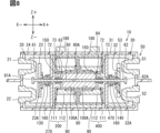
- the electromagnetic relay 10 in the second embodiment has two of each of the fixed yoke 70, excitation coil 100, magnetic circuit member 90, return spring 150, holding member 160, and power supply unit 180.
- the fixed yoke 70 on one end side X- may be referred to as one end side fixed yoke 270.
- the fixed yoke 70 on the other end side X+ may be referred to as the other end side fixed yoke 470.
- the excitation coil 100 on one end side X- may be referred to as one end side excitation coil 200.
- the excitation coil 100 on the other end side X+ may be referred to as the other end side excitation coil 400.
- Figure 8 is a cross-sectional view of the electromagnetic relay 10 in the second embodiment when not energized.
- Figure 9 is a cross-sectional view of the electromagnetic relay 10 in the second embodiment when the one-end excitation coil 200 is energized.
- Figure 10 is a cross-sectional view of the electromagnetic relay in the second embodiment when the other-end excitation coil is energized.
- a contact device 20 for a series circuit is also provided in the internal space of one end side X- of the base 170.
- a contact device 30 for a parallel circuit is provided in the internal space of the other end side X+ of the base 170.
- Two power supply units 180 are provided on the side of the base 170.
- One of the power supply units 180 has the function of switching between energizing and de-energizing the one-end excitation coil 200.
- the other power supply unit 180 has the function of switching between energizing and de-energizing the other-end excitation coil 400.
- a return spring 150, one-end fixed yoke 270, one-end contact spring 130, and first movable part 23 are passed from the other end side X+ to the one end side X- at a portion of the shaft 60 closer to the one end side X- than the portion where the movable yoke 80 is provided.
- the return spring 150 is provided in a recess 72 of the one-end fixed yoke 270.
- the return spring 150 is held in a compressed state between the one-end fixed yoke 270 and the movable yoke 80.
- the one-end fixed yoke 270 and the movable yoke 80 are separated in the axial direction X by a first air gap 83.
- a retaining member 160 that holds the spring is fixed to the shaft 60 at a position on the one end side X-, closer to the one end side fixed yoke 270.
- the retaining member 160 has a cone shape with a bottom on the other end side X+.
- the one end side pressure spring 130 is held in the internal space of the retaining member 160.
- the one end side pressure spring 130 is held in a compressed state between the retaining member 160 and the first movable part 23.
- a return spring 150, an other-end fixed yoke 470, an other-end contact spring 140, and an insulating member 32 are passed from one end X- to the other end X+ at a portion of the shaft 60 closer to the other end X+ than the portion where the movable yoke 80 is provided.
- the return spring 150 is provided in a recess 72 in the other-end fixed yoke 470.
- the return spring 150 is held in a compressed state between the other-end fixed yoke 470 and the movable yoke 80.
- the fixed yoke 70 and the movable yoke 80 are separated in the axial direction by a second air gap 84.
- a holding member 160 that holds the other end pressure spring 140 is fixed to the shaft 60 at a position on the other end side X+ closer to the other end side fixed yoke 470.
- the holding member 160 has a cone shape with a bottom on the one end side X-.
- the other end pressure spring 140 is held in the internal space of the holding member 160.
- the other end pressure spring 140 is held in a compressed state between the holding member 160 and the insulating member 32.
- the magnetic circuit member 90 and the one-end excitation coil 200 are provided so as to radially overlap a portion of the one-end fixed yoke 270, the return spring 150, and a portion of the movable yoke 80.
- the magnetic circuit member 90 and the other-end excitation coil 400 are provided so as to radially overlap a portion of the other-end fixed yoke 470, the return spring 150, and a portion of the movable yoke 80.
- Two excitation coils 100 are arranged in the axial direction X and passed through the shaft 60 so as to overlap radially with the one-end fixed yoke 270, the movable yoke 80, and the other-end fixed yoke 470.
- a magnetic circuit member 90 is provided so as to cover the inner and outer diameters of the one-end excitation coil 200 and the other-end side X+.
- a magnetic circuit member 90 is provided so as to cover the inner and outer diameters of the other-end excitation coil 400 and the one-end side X-.
- the two magnetic circuit members 90 are bent into an approximately U-shape and extend in the circumferential direction so as to cover the excitation coils 200, 400.
- a first air gap 83 and a second air gap 84 are generated.
- the first movable part 23 is not in contact with the first fixed part 21 and the second fixed part 22.
- the second movable part 43 is not in contact with the third fixed part 41 and the fourth fixed part 42.
- the third movable part 53 is not in contact with the fifth fixed part 51 and the sixth fixed part 52.
- a magnetic circuit is formed via the one-end fixed yoke 270, the movable yoke 80, and the magnetic circuit member 90.
- a current is applied to the conductor 112 in a clockwise direction as viewed from the one-end side X-, a counterclockwise magnetic circuit is formed on the upper side Z+ and a clockwise magnetic circuit is formed on the lower side Z- in a cross section cut along a plane perpendicular to the depth direction Y. Accordingly, an electromagnetic force is generated acting from the other end side X+ to the one end side X-.
- the electromagnetic force causes the shaft 60 and movable yoke 80 to move in the first direction toward the one-end fixed yoke 270.
- the shaft 60 moves in the first direction to a position where the movable yoke 80 contacts the one-end fixed yoke 270.
- the first air gap 83 disappears.
- a retaining member 160 that holds the one-end pressure spring 130 is fixed to a portion of the shaft 60 closer to the one-end side X- than the one-end fixed yoke 270.
- the retaining member 160 presses the one-end pressure spring 130 and the first movable part 23 towards the one-end side X-.
- the first movable part 23 is pressed against the first fixed part 21 and the second fixed part 22 by receiving a pressing force from the holding member 160 via the one-end contact spring 130.
- the first movable part 23 is in contact with the first fixed part 21 and the second fixed part 22 by receiving a biasing force from the one-end contact spring 130 toward the one-end side X-.
- the first movable part 23 maintains contact with the first fixed part 21 and the second fixed part 22 while current is maintained flowing to the one-end excitation coil 200.
- the series circuit contact device 20 when current is being passed from the power supply unit 180 to the one-end excitation coil 200, the series circuit contact device 20 is in the on state. While current is being passed from the power supply unit 180 to the one-end excitation coil 200, the first battery 2A and the second battery 2B continue to be connected in series.
- a magnetic circuit is formed via the other end fixed yoke 470, the movable yoke 80, and the magnetic circuit member 90.
- a current is supplied to the conductor 112 in a clockwise direction as viewed from the other end side X+, a counterclockwise magnetic circuit is formed on the upper side Z+ and a clockwise magnetic circuit is formed on the lower side Z- in a cross section cut along a plane perpendicular to the depth direction. Accordingly, an electromagnetic force is generated that acts from the one end side X- to the other end side X+.
- the electromagnetic force causes the shaft 60 and the movable yoke 80 to move in the second direction toward the other end fixed yoke 470.
- the shaft 60 moves in the second direction to a position where the movable yoke 80 contacts the other end fixed yoke 470.
- the second air gap 84 disappears.
- a retaining member 160 that holds the other end pressure spring 140 is fixed to a portion of the shaft 60 closer to the other end side X+ than the other end fixed yoke 470.
- the retaining member 160 presses the other end pressure spring 140 and the insulating member 32 toward the other end side X+.
- the second movable part 43 is pressed against the third fixed part 41 and the fourth fixed part 42 by receiving a pressing force from the retaining member 160 via the other end side pressure spring 140.
- the second movable part 43 is in contact with the third fixed part 41 and the fourth fixed part 42 by receiving a biasing force from the other end side pressure spring 140 that biases it axially toward the other end side X+.
- the second movable part 43 maintains contact with the third fixed part 41 and the fourth fixed part 42 while current is maintained flowing to the other end side excitation coil 400.
- the third movable part 53 is pressed against the fifth fixed part 51 and the sixth fixed part 52 by receiving a pressing force from the holding member 160 via the other end side contact spring 140.
- the third movable part 53 is in contact with the fifth fixed part 51 and the sixth fixed part 52 by receiving a biasing force from the other end side contact spring 140 that biases it axially toward the other end side X+.
- the third movable part 53 maintains contact with the fifth fixed part 51 and the sixth fixed part 52 while the other end side excitation coil 400 is energized. That is, when the power supply part 180 is energizing the other end side excitation coil 400, the parallel circuit contact device 30 is in the ON state. While the power supply part 180 is energizing the other end side excitation coil 400, the first battery 2A and the second battery 2B are continuously connected in parallel.
- the second embodiment also achieves the same effects as the first embodiment. Furthermore, in the second embodiment, when no current is applied to the excitation coil 100, the fixed part and the movable part are separated, so that the current is cut off at the same time as the power supply. This can increase redundancy when the power supply is off.
- the number of turns of the conductor 112 in the other-end excitation coil 400 is greater than the number of turns of the conductor 112 in the one-end excitation coil 200.
- the electromagnetic force in the second direction is made higher than the electromagnetic force in the first direction.
- the contact pressure between the movable part and the fixed part of each contact device is set to be approximately equal. This suppresses variation in the connection state between the movable part and the fixed part.
- the electromagnetic relay 10 in the third embodiment further includes a permanent magnet 300 in addition to the components described in the second embodiment.
- the third embodiment still includes only one power supply unit 180.
- An end of the other end side excitation coil 400 is connected to the power supply unit 180.
- Another end of the other end side excitation coil 400 is electrically connected to an end of the one end side excitation coil 200.
- FIG. 11 is a cross-sectional view of the electromagnetic relay 10 in the initial state in the third embodiment.
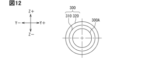
- FIG. 12 is a plan view of the permanent magnet 300.
- FIG. 13 is a plan view of the permanent magnet 300.
- FIG. 14 is a cross-sectional view of the electromagnetic relay 10 when connected in series in the third embodiment.
- FIG. 15 is a cross-sectional view of the electromagnetic relay 10 when connected in series in the third embodiment.
- FIG. 16 is a cross-sectional view of the electromagnetic relay 10 when connected in parallel in the third embodiment.
- FIG. 17 is a cross-sectional view of the electromagnetic relay 10 when connected in parallel in the third embodiment.
- a permanent magnet 300 is provided between two excitation coils 100 arranged in the axial direction X.
- the permanent magnet 300 has a through hole 300A in the axial direction X.
- the permanent magnet 300 has an annular shape extending in an annular shape around the axial direction.
- the permanent magnet pieces 330 may be arranged in an annular shape with gaps 300B between them to form a substantially annular shape.
- the permanent magnet pieces 330 may be substantially fan-shaped when viewed from the axial direction X.
- the permanent magnet 300 is magnetized with an S pole 310 and an N pole 320 in the radial direction.
- the S pole 310 is provided on the radial inside, and the N pole 320 is provided on the radial outside.
- the magnetic circuit member 90 comprises an inner magnetic circuit member 91 and an outer magnetic circuit member 92.
- the inner magnetic circuit member 91 and the outer magnetic circuit member 92 have a cylindrical shape.
- the inner magnetic circuit member 91 is provided inside the two excitation coils 100 in the radial direction.
- the outer magnetic circuit member 92 is provided outside the two excitation coils 100 in the radial direction.
- the inner magnetic circuit member 91 is provided between the two excitation coils 100 and the permanent magnet 300 and the movable yoke 80.
- the outer magnetic circuit member 92 is provided outside in the radial direction so as to overlap the two excitation coils 100 and the permanent magnet 300.
- a first air gap 83 is generated between the one end side fixed yoke 270 and the movable yoke 80.
- a second air gap 84 is generated between the other end side fixed yoke 470 and the movable yoke 80.
- the first movable part 23 is not in contact with the first fixed part 21 and the second fixed part 22.
- the second movable part 43 is not in contact with the third fixed part 41 and the fourth fixed part 42.
- the third movable part 53 is not in contact with the fifth fixed part 51 and the sixth fixed part 52.
- a magnetic circuit is formed via the other end fixed yoke 470, the movable yoke 80, and the magnetic circuit member 90.
- a counterclockwise magnetic circuit is formed at one end side X- and the other end side X+ of the upper side Z+ in a cross section cut along a plane perpendicular to the depth direction Y.
- a clockwise magnetic circuit is formed at one end side X- and the other end side X+ of the lower side Z-.
- the magnetic circuit due to the magnetic field generated by the excitation coil 100 is shown by a solid line.
- a magnetic field is generated by excitation of the permanent magnet 300.
- the magnetic field generated by the permanent magnet 300 is indicated by a two-dot chain line.
- the permanent magnet 300 is arranged so that the radially inner side corresponds to the N pole 320 and the radially outer side corresponds to the S pole 310, so that a magnetic field is generated in a clockwise direction from the N pole 320 to the S pole 310 on the upper side Z+ of the other end side X+ in the axial direction X.
- a magnetic field is generated in a counterclockwise direction from the N pole 320 to the S pole 310 on the lower side Z- of the other end side X+ in the axial direction X.
- a counterclockwise magnetic circuit is formed by the excitation coil 100, and a clockwise magnetic field is formed by the permanent magnet 300.
- the magnetic fluxes cancel each other out. It can also be said that the magnetic fluxes are offset.
- a clockwise magnetic circuit is formed by the excitation coil 100, and a counterclockwise magnetic field is formed by the permanent magnet 300.
- the magnetic fluxes cancel each other out. It can also be said that the magnetic fluxes are offset.
- a counterclockwise magnetic circuit is formed by the excitation coil 100, and a counterclockwise magnetic field is formed by the permanent magnet 300.
- the magnetic fluxes reinforce each other. It can also be said that the magnetic flux is amplified.
- a clockwise magnetic circuit is formed by the excitation coil 100, and a clockwise magnetic field is formed by the permanent magnet 300.
- the magnetic fluxes reinforce each other. It can also be said that the magnetic flux is amplified.
- an electromagnetic force is generated acting from the other end side X+ to one end side X-.
- the electromagnetic force causes the shaft 60 and the movable yoke 80 to move in the first direction toward the one-end fixed yoke 270.
- the shaft 60 moves in the first direction to a position where the movable yoke 80 contacts the one-end fixed yoke 270.
- the first air gap 83 disappears.
- the second air gap 84 widens.
- the retaining member 160 presses the one-end pressure spring 130 and the first movable part 23 towards the one-end side X-.
- the first movable part 23 receives a pressing force from the retaining member 160 via the one-end pressure spring 130 and is pressed against the first fixed part 21 and the second fixed part 22.
- the first movable part 23 receives a biasing force from the one-end pressure spring 130 in the first direction and is in contact with the first fixed part 21 and the second fixed part 22.
- the series circuit is turned on.
- the control device 1A has the function of switching between energized and de-energized state of the excitation coil 100.
- the control device 1A detects that the first movable part 23 has come into contact with the first fixed part 21 and the second fixed part 22, it cuts off the flow of electricity to the excitation coil 100.
- the contact between the first movable part 23 and the first fixed part 21 and the second fixed part 22 is maintained. In other words, the ON state of the series circuit is maintained.
- the force with which the one-end fixed yoke 270 attracts the movable yoke 80 is greater than the force with which the other-end fixed yoke 470 attracts the movable yoke 80.
- the force with which the one-end fixed yoke 270 attracts the movable yoke 80 is always greater than the force with which the other-end fixed yoke 470 attracts the movable yoke 80. This maintains the state in which the movable yoke 80 is attracted to the one-end fixed yoke 270. Even when the current to the excitation coil 100 is cut off, contact between the first movable part 23 and the first fixed part 21 and second fixed part 22 is maintained. In other words, the on state of the series circuit is maintained.
- a clockwise magnetic circuit is formed by the excitation coil 100, and a counterclockwise magnetic field is formed by the permanent magnet 300.
- the magnetic fluxes cancel each other out. It can also be said that the magnetic fluxes are offset.
- a counterclockwise magnetic circuit is formed by the excitation coil 100, and a clockwise magnetic field is formed by the permanent magnet 300. Below one end side X- in the axial direction X, the magnetic fluxes cancel each other out. It can also be said that the magnetic fluxes are offset.
- a clockwise magnetic circuit is formed by the excitation coil 100, and a clockwise magnetic field is formed by the permanent magnet 300.
- the magnetic fluxes reinforce each other. It can also be said that the magnetic flux is amplified.
- a counterclockwise magnetic circuit is formed by the excitation coil 100, and a counterclockwise magnetic field is formed by the permanent magnet 300.
- the magnetic fluxes reinforce each other. It can also be said that the magnetic flux is amplified.
- an electromagnetic force acting in the second direction is generated.
- the electromagnetic force causes the shaft 60 and movable yoke 80 to move in the second direction toward the other end side fixed yoke 470.
- the shaft 60 moves in the second direction to a position where the movable yoke 80 contacts the other end side fixed yoke 470.
- the second air gap 84 disappears.
- the first air gap 83 widens.
- the retaining member 160 presses the other end side contact spring 140 and the insulating member 32 toward the other end side X+.
- the second movable part 43 is pressed against the third fixed part 41 and the fourth fixed part 42 by receiving a pressing force from the holding member 160 via the other end side contact spring 140.
- the second movable part 43 is in contact with the third fixed part 41 and the fourth fixed part 42 by receiving a biasing force from the other end side contact spring 140 to the other end side X+ in the axial direction X.
- the third movable part 53 is pressed against the fifth fixed part 51 and the sixth fixed part 52 by receiving a pressing force from the holding member 160 via the other end side contact spring 140.
- the third movable part 53 is in contact with the fifth fixed part 51 and the sixth fixed part 52 by receiving a biasing force from the other end side contact spring 140 to the other end side X+ in the axial direction X.
- the parallel circuit is turned on.
- control device 1A When the control device 1A detects that the second movable part 43 and the third movable part 53 are in contact with the third fixed part 41, the fourth fixed part 42, the fifth fixed part 51, and the sixth fixed part 52, it cuts off the flow of electricity to the excitation coil 100.
- the contact between the second movable part 43 and the third fixed part 41 and the fourth fixed part 42 is maintained.
- the contact between the third movable part 53 and the fifth fixed part 51 and the sixth fixed part 52 is maintained. In other words, the on state of the parallel circuit is maintained.
- the force with which the other-end fixed yoke 470 attracts the movable yoke 80 is greater than the force with which the one-end fixed yoke 270 attracts the movable yoke 80.
- the force with which the other-end fixed yoke 470 attracts the movable yoke 80 is always greater than the force with which the one-end fixed yoke 270 attracts the movable yoke 80. This maintains the state in which the movable yoke 80 is attracted to the other-end fixed yoke 470. Even when the current to the excitation coil 100 is cut off, the contact between the second movable part 43 and the third fixed part 41 and the fourth fixed part 42 is maintained. Even when the current to the excitation coil 100 is cut off, the contact between the third movable part 53 and the fifth fixed part 51 and the sixth fixed part 52 is maintained. In other words, the on state of the parallel circuit is maintained.
- the third embodiment also achieves the same effects as the first embodiment. Furthermore, in the third embodiment, even when the current to the excitation coil 100 is cut off, the contact between the movable contact and the fixed contact is maintained, so that even greater power savings are possible than in the first embodiment.
- the electromagnetic relay 10 has been described as having a series circuit contact device 20 and a parallel circuit contact device 30.
- the parallel circuit contact device 30 described so far includes a first parallel circuit contact device 40 and a second parallel circuit contact device 50.
- the parallel circuit contact device 30 in the fourth embodiment does not need to include both the first parallel circuit contact device 40 and the second parallel circuit contact device 50.
- FIG. 18 is an electric circuit diagram of the power conversion device 1 in the fourth embodiment.
- the parallel circuit contact device 30 in the fourth embodiment may include either the first parallel circuit contact device 40 or the second parallel circuit contact device 50.
- the electromagnetic relay 10 in the fourth embodiment has a first contact device 420 corresponding to the series circuit contact device 20 and a second contact device 440 corresponding to the first parallel circuit contact device 40.
- the mechanical structure of the second contact device 440 is the same as the mechanical structure of the first contact device 420.
- the mechanical structure of the first contact device 420 is similar to that of the series circuit contact device 20, and therefore a description thereof will be omitted.
- the batteries 2A and 2B include a first battery 2A and a second battery 2B.
- a first contact device 420 is provided between the first battery 2A and the second battery 2B.
- the negative electrode of the first battery 2A is connected to the first fixed portion 21 of the first contact device 420 via a first connecting wire 6.
- the positive electrode of the second battery 2B is connected to the second fixed portion 22 of the first contact device 420 via a second connecting wire 7.
- a second contact device 440 is provided between the first connecting wire 6 and the negative bus bar 9.
- the first connecting wire 6 and the third fixed portion 41 of the second contact device 440 are connected via the third connecting wire 11.
- the fourth fixed portion 42 of the second contact device 440 and the negative bus bar 9 are connected via the fourth connecting wire 12.
- the second contact device 440 is in the on state, the second movable portion 43 of the second contact device 440 contacts the third fixed portion 41 and the fourth fixed portion 42. Accordingly, the first connecting wire 6 and the negative bus bar 9 are electrically connected.
- the electromagnetic relay 10 of the fourth embodiment it is possible to switch between a current path passing through both the first battery 2A and the second battery 2B and a current path passing only through the first battery 2A.
- the electromagnetic relay 10 in the fourth embodiment may have a first contact device 420 and a third contact device 450 equivalent to the second parallel circuit contact device 50.
- the electromagnetic relay 10 in the fourth embodiment it is possible to switch between a current path passing through both the first battery 2A and the second battery 2B, and a current path passing only through the second battery 2B.
- the electromagnetic relay 10 does not have to switch between series and parallel of the batteries 2A and 2B as in the forms described so far. It is sufficient that the electromagnetic relay 10 can switch between at least two current paths.
- the other end movable parts are provided at a distance sufficient to maintain electrical insulation, and a through hole (32A) for passing the shaft is formed at a position equidistant from the center (43A, 53A) of each of the other end movable parts.
- the other end movable parts are provided at a distance sufficient to maintain electrical insulation, and a plate-shaped insulating member (32) having electrical insulation properties is further provided.
- An electromagnetic relay as described in technical idea 1 or 2 in which the insulating member moves in the second direction as the shaft moves in the second direction, thereby bringing into contact a plurality of the other-end side movable parts and a plurality of the other-end side fixed parts.
- the excitation coil includes two coils.
- the two excitation coils are arranged around the shaft and are aligned in the axial direction such that the central holes are in communication with each other,
- An electromagnetic relay according to technical idea 1 or 2 in which, when current is applied to the other-end excitation coil (400), which is one of the two excitation coils, an electromagnetic force directed in the second direction moves the multiple other-end movable parts to a position where they come into contact with the multiple other-end fixed parts.
- the excitation coil includes two coils.
- the permanent magnet is provided between the two excitation coils, the two excitation coils are arranged around the shaft and are aligned in the axial direction such that the central holes are in communication with each other,
- An electromagnetic relay as described in Technical Idea 1 or 2, in which a gap (83) is provided between the one-end side fixed yoke and the movable yoke when the multiple other-end side movable parts and the multiple other-end side fixed parts are in contact.
- an other end side fixed yoke (470) is provided, which is aligned with the movable yoke in the axial direction and restricts the movement of the movable yoke in the second direction, and whose axial position is determined on the other end side of the movable yoke,
Landscapes
- Physics & Mathematics (AREA)
- Electromagnetism (AREA)
- Electromagnets (AREA)
Priority Applications (3)
| Application Number | Priority Date | Filing Date | Title |
|---|---|---|---|
| CN202380084923.7A CN120457514A (zh) | 2022-12-14 | 2023-11-27 | 电磁继电器 |
| JP2024564253A JPWO2024127959A1 (https=) | 2022-12-14 | 2023-11-27 | |
| DE112023005149.6T DE112023005149T5 (de) | 2022-12-14 | 2023-11-27 | Elektromagnetisches Relais |
Applications Claiming Priority (2)
| Application Number | Priority Date | Filing Date | Title |
|---|---|---|---|
| JP2022-199675 | 2022-12-14 | ||
| JP2022199675 | 2022-12-14 |
Publications (1)
| Publication Number | Publication Date |
|---|---|
| WO2024127959A1 true WO2024127959A1 (ja) | 2024-06-20 |
Family
ID=91484855
Family Applications (1)
| Application Number | Title | Priority Date | Filing Date |
|---|---|---|---|
| PCT/JP2023/042309 Ceased WO2024127959A1 (ja) | 2022-12-14 | 2023-11-27 | 電磁継電器 |
Country Status (4)
| Country | Link |
|---|---|
| JP (1) | JPWO2024127959A1 (https=) |
| CN (1) | CN120457514A (https=) |
| DE (1) | DE112023005149T5 (https=) |
| WO (1) | WO2024127959A1 (https=) |
Citations (6)
| Publication number | Priority date | Publication date | Assignee | Title |
|---|---|---|---|---|
| JPS577248U (https=) * | 1980-06-13 | 1982-01-14 | ||
| JPH027131B2 (https=) * | 1981-04-30 | 1990-02-15 | Matsushita Electric Works Ltd | |
| JP2010073352A (ja) * | 2008-09-16 | 2010-04-02 | Denso Corp | 電磁継電器 |
| JP2013232341A (ja) * | 2012-04-27 | 2013-11-14 | Fuji Electric Co Ltd | 電磁開閉器 |
| JP2014170738A (ja) * | 2013-02-08 | 2014-09-18 | Nippon Soken Inc | ソレノイド装置、およびソレノイド制御システム |
| JP2022087465A (ja) * | 2020-12-01 | 2022-06-13 | 株式会社オートネットワーク技術研究所 | 車両用電源装置 |
Family Cites Families (1)
| Publication number | Priority date | Publication date | Assignee | Title |
|---|---|---|---|---|
| JPH037248U (https=) * | 1989-06-09 | 1991-01-24 |
-
2023
- 2023-11-27 JP JP2024564253A patent/JPWO2024127959A1/ja active Pending
- 2023-11-27 WO PCT/JP2023/042309 patent/WO2024127959A1/ja not_active Ceased
- 2023-11-27 DE DE112023005149.6T patent/DE112023005149T5/de active Pending
- 2023-11-27 CN CN202380084923.7A patent/CN120457514A/zh active Pending
Patent Citations (6)
| Publication number | Priority date | Publication date | Assignee | Title |
|---|---|---|---|---|
| JPS577248U (https=) * | 1980-06-13 | 1982-01-14 | ||
| JPH027131B2 (https=) * | 1981-04-30 | 1990-02-15 | Matsushita Electric Works Ltd | |
| JP2010073352A (ja) * | 2008-09-16 | 2010-04-02 | Denso Corp | 電磁継電器 |
| JP2013232341A (ja) * | 2012-04-27 | 2013-11-14 | Fuji Electric Co Ltd | 電磁開閉器 |
| JP2014170738A (ja) * | 2013-02-08 | 2014-09-18 | Nippon Soken Inc | ソレノイド装置、およびソレノイド制御システム |
| JP2022087465A (ja) * | 2020-12-01 | 2022-06-13 | 株式会社オートネットワーク技術研究所 | 車両用電源装置 |
Also Published As
| Publication number | Publication date |
|---|---|
| CN120457514A (zh) | 2025-08-08 |
| DE112023005149T5 (de) | 2025-09-25 |
| JPWO2024127959A1 (https=) | 2024-06-20 |
Similar Documents
| Publication | Publication Date | Title |
|---|---|---|
| US9595411B2 (en) | Electromagnetic relay | |
| US8847714B2 (en) | Relay | |
| JP5806562B2 (ja) | 電磁接触器 | |
| EP2472538B1 (en) | Electromagnetic relay | |
| JP5918424B2 (ja) | 電磁接触器 | |
| US8901445B2 (en) | Magnetic contactor | |
| US12387897B2 (en) | Contact apparatus and electromagnetic relay | |
| JP2015079672A (ja) | 電磁継電器 | |
| US20200286702A1 (en) | Contact module, contact device, electromagnetic relay module, and electrical device | |
| KR20180113453A (ko) | 전자기 릴레이 | |
| JP2025030061A (ja) | 継電器及び継電ユニット | |
| JP2011108452A (ja) | 電磁継電器 | |
| JP5549642B2 (ja) | 継電器 | |
| CA2874724C (en) | Electrical switching apparatus and relay including a ferromagnetic or magnetic armature having a tapered portion | |
| EP3706152B1 (en) | Electromagnetic relay | |
| WO2024127959A1 (ja) | 電磁継電器 | |
| JP2014112482A (ja) | 電磁接触器 | |
| JP2019140207A (ja) | 電磁石装置及び電磁継電器 | |
| JP7357193B2 (ja) | 電磁継電器 | |
| JP2012256451A (ja) | 電磁継電器及び電磁継電器の製造方法 | |
| WO2025154395A1 (ja) | 電磁継電器 | |
| JP2019096563A (ja) | 接点装置、及び電磁継電器 | |
| JP2000082374A (ja) | 電磁接触器の電磁石装置 | |
| JP2025043191A (ja) | 電磁継電器 | |
| JPH08138509A (ja) | 直流電磁接触器 |
Legal Events
| Date | Code | Title | Description |
|---|---|---|---|
| 121 | Ep: the epo has been informed by wipo that ep was designated in this application |
Ref document number: 23903253 Country of ref document: EP Kind code of ref document: A1 |
|
| WWE | Wipo information: entry into national phase |
Ref document number: 2024564253 Country of ref document: JP |
|
| WWE | Wipo information: entry into national phase |
Ref document number: 202380084923.7 Country of ref document: CN |
|
| WWE | Wipo information: entry into national phase |
Ref document number: 112023005149 Country of ref document: DE |
|
| WWP | Wipo information: published in national office |
Ref document number: 202380084923.7 Country of ref document: CN |
|
| WWP | Wipo information: published in national office |
Ref document number: 112023005149 Country of ref document: DE |
|
| 122 | Ep: pct application non-entry in european phase |
Ref document number: 23903253 Country of ref document: EP Kind code of ref document: A1 |