WO2024127653A1 - エアロゾル生成装置の電源ユニット、及び、エアロゾル生成装置 - Google Patents
エアロゾル生成装置の電源ユニット、及び、エアロゾル生成装置 Download PDFInfo
- Publication number
- WO2024127653A1 WO2024127653A1 PCT/JP2022/046474 JP2022046474W WO2024127653A1 WO 2024127653 A1 WO2024127653 A1 WO 2024127653A1 JP 2022046474 W JP2022046474 W JP 2022046474W WO 2024127653 A1 WO2024127653 A1 WO 2024127653A1
- Authority
- WO
- WIPO (PCT)
- Prior art keywords
- sensor
- power supply
- case
- wiring
- wiring layer
- Prior art date
- Legal status (The legal status is an assumption and is not a legal conclusion. Google has not performed a legal analysis and makes no representation as to the accuracy of the status listed.)
- Ceased
Links
Images






Classifications
-
- A—HUMAN NECESSITIES
- A24—TOBACCO; CIGARS; CIGARETTES; SIMULATED SMOKING DEVICES; SMOKERS' REQUISITES
- A24F—SMOKERS' REQUISITES; MATCH BOXES; SIMULATED SMOKING DEVICES
- A24F40/00—Electrically operated smoking devices; Component parts thereof; Manufacture thereof; Maintenance or testing thereof; Charging means specially adapted therefor
- A24F40/50—Control or monitoring
-
- A—HUMAN NECESSITIES
- A24—TOBACCO; CIGARS; CIGARETTES; SIMULATED SMOKING DEVICES; SMOKERS' REQUISITES
- A24F—SMOKERS' REQUISITES; MATCH BOXES; SIMULATED SMOKING DEVICES
- A24F40/00—Electrically operated smoking devices; Component parts thereof; Manufacture thereof; Maintenance or testing thereof; Charging means specially adapted therefor
- A24F40/50—Control or monitoring
- A24F40/51—Arrangement of sensors
-
- A—HUMAN NECESSITIES
- A24—TOBACCO; CIGARS; CIGARETTES; SIMULATED SMOKING DEVICES; SMOKERS' REQUISITES
- A24F—SMOKERS' REQUISITES; MATCH BOXES; SIMULATED SMOKING DEVICES
- A24F40/00—Electrically operated smoking devices; Component parts thereof; Manufacture thereof; Maintenance or testing thereof; Charging means specially adapted therefor
- A24F40/10—Devices using liquid inhalable precursors
-
- A—HUMAN NECESSITIES
- A24—TOBACCO; CIGARS; CIGARETTES; SIMULATED SMOKING DEVICES; SMOKERS' REQUISITES
- A24F—SMOKERS' REQUISITES; MATCH BOXES; SIMULATED SMOKING DEVICES
- A24F40/00—Electrically operated smoking devices; Component parts thereof; Manufacture thereof; Maintenance or testing thereof; Charging means specially adapted therefor
- A24F40/20—Devices using solid inhalable precursors
-
- A—HUMAN NECESSITIES
- A24—TOBACCO; CIGARS; CIGARETTES; SIMULATED SMOKING DEVICES; SMOKERS' REQUISITES
- A24F—SMOKERS' REQUISITES; MATCH BOXES; SIMULATED SMOKING DEVICES
- A24F40/00—Electrically operated smoking devices; Component parts thereof; Manufacture thereof; Maintenance or testing thereof; Charging means specially adapted therefor
- A24F40/40—Constructional details, e.g. connection of cartridges and battery parts
-
- A—HUMAN NECESSITIES
- A24—TOBACCO; CIGARS; CIGARETTES; SIMULATED SMOKING DEVICES; SMOKERS' REQUISITES
- A24F—SMOKERS' REQUISITES; MATCH BOXES; SIMULATED SMOKING DEVICES
- A24F40/00—Electrically operated smoking devices; Component parts thereof; Manufacture thereof; Maintenance or testing thereof; Charging means specially adapted therefor
- A24F40/40—Constructional details, e.g. connection of cartridges and battery parts
- A24F40/46—Shape or structure of electric heating means
-
- A—HUMAN NECESSITIES
- A24—TOBACCO; CIGARS; CIGARETTES; SIMULATED SMOKING DEVICES; SMOKERS' REQUISITES
- A24F—SMOKERS' REQUISITES; MATCH BOXES; SIMULATED SMOKING DEVICES
- A24F40/00—Electrically operated smoking devices; Component parts thereof; Manufacture thereof; Maintenance or testing thereof; Charging means specially adapted therefor
- A24F40/50—Control or monitoring
- A24F40/53—Monitoring, e.g. fault detection
-
- H—ELECTRICITY
- H05—ELECTRIC TECHNIQUES NOT OTHERWISE PROVIDED FOR
- H05B—ELECTRIC HEATING; ELECTRIC LIGHT SOURCES NOT OTHERWISE PROVIDED FOR; CIRCUIT ARRANGEMENTS FOR ELECTRIC LIGHT SOURCES, IN GENERAL
- H05B3/00—Ohmic-resistance heating
- H05B3/0019—Circuit arrangements
-
- H—ELECTRICITY
- H05—ELECTRIC TECHNIQUES NOT OTHERWISE PROVIDED FOR
- H05B—ELECTRIC HEATING; ELECTRIC LIGHT SOURCES NOT OTHERWISE PROVIDED FOR; CIRCUIT ARRANGEMENTS FOR ELECTRIC LIGHT SOURCES, IN GENERAL
- H05B3/00—Ohmic-resistance heating
- H05B3/40—Heating elements having the shape of rods or tubes
-
- H—ELECTRICITY
- H05—ELECTRIC TECHNIQUES NOT OTHERWISE PROVIDED FOR
- H05B—ELECTRIC HEATING; ELECTRIC LIGHT SOURCES NOT OTHERWISE PROVIDED FOR; CIRCUIT ARRANGEMENTS FOR ELECTRIC LIGHT SOURCES, IN GENERAL
- H05B6/00—Heating by electric, magnetic or electromagnetic fields
- H05B6/02—Induction heating
- H05B6/10—Induction heating apparatus, other than furnaces, for specific applications
- H05B6/105—Induction heating apparatus, other than furnaces, for specific applications using a susceptor
- H05B6/108—Induction heating apparatus, other than furnaces, for specific applications using a susceptor for heating a fluid
-
- H—ELECTRICITY
- H05—ELECTRIC TECHNIQUES NOT OTHERWISE PROVIDED FOR
- H05B—ELECTRIC HEATING; ELECTRIC LIGHT SOURCES NOT OTHERWISE PROVIDED FOR; CIRCUIT ARRANGEMENTS FOR ELECTRIC LIGHT SOURCES, IN GENERAL
- H05B2203/00—Aspects relating to Ohmic resistive heating covered by group H05B3/00
- H05B2203/014—Heaters using resistive wires or cables not provided for in H05B3/54
Definitions
- the present disclosure relates to a power supply unit for an aerosol generating device and an aerosol generating device.
- the aerosol generating device has a case that contains a power source, a heating unit, multiple sensors, and a circuit board that mounts the sensors and control device. Furthermore, flexible printed circuit boards may be used in aerosol generating devices to achieve compact size.
- Patent Document 1 describes an aerosol generating device that includes a rigid substrate and a flexible printed circuit board.
- Aerosol generating devices such as heated smoking devices are preferably small enough to fit in the user's hand, and therefore must be compact.
- miniaturizing an aerosol generating device makes it easier for external noise such as static electricity to invade a circuit board, including a flexible printed circuit board, from outside the aerosol generating device.
- external noise such as static electricity invades a circuit board, including a flexible printed circuit board, from outside the aerosol generating device, an overvoltage or overcurrent is input to a sensor mounted on the circuit board, which may result in false detection or failure of the sensor.
- This disclosure discloses a power supply unit for an aerosol generating device that can prevent a sensor mounted on a flexible printed circuit board from false detection or failure due to external noise, and the aerosol generating device.
- the power supply unit of the aerosol generating device of the present disclosure comprises: A power source capable of supplying power to a heating unit that heats at least one of the aerosol source and the flavor source; A flexible printed circuit board on which one or more sensors are mounted or electrically connected; a case that accommodates the power supply and the flexible printed wiring board; A power supply unit for an aerosol generating device, comprising: The flexible printed wiring board has a first wiring layer and a second wiring layer laminated thereon, A signal wiring is formed in at least one of the first wiring layer and the second wiring layer, In a case facing region of the flexible printed wiring board that faces the case, the wiring area of the signal wiring formed in the layer of the first wiring layer or the second wiring layer that is closer to the case is smaller than the wiring area of the signal wiring formed in the layer farther from the case.
- the aerosol generating device of the present disclosure comprises: A heating unit that heats at least one of the aerosol source and the flavor source; A power source capable of supplying power to the heating unit; A flexible printed circuit board on which one or more sensors are mounted or electrically connected; a case that accommodates the heating unit, the power source, and the flexible printed wiring board;
- An aerosol generating device comprising: The flexible printed wiring board has a first wiring layer and a second wiring layer laminated thereon, A signal wiring is formed in at least one of the first wiring layer and the second wiring layer, In a case facing region of the flexible printed wiring board that faces the case, the wiring area of the signal wiring formed in the layer of the first wiring layer or the second wiring layer that is closer to the case is smaller than the wiring area of the signal wiring formed in the layer farther from the case.
- This disclosure makes it possible to prevent sensors mounted on flexible printed circuit boards from false detection or malfunctioning due to external noise.
- FIG. 1 is a schematic diagram showing a first configuration example of a suction device (suction device 100A).
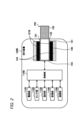
- FIG. 2 is a schematic diagram showing a second configuration example (suction device 100B) of the suction device.
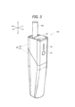
- FIG. 3 is an overall perspective view of a suction device 100 which is one embodiment of the suction device of the present disclosure.
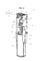
- FIG. 4 is a perspective view of the internal unit 10 as viewed from the front right side.
- FIG. 5 is a perspective view of the internal unit 10 as viewed from the front left side.
- FIG. 6 is an exploded perspective view of the internal unit 10.
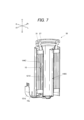
- FIG. 7 is a cross-sectional perspective view of heater assembly 30. As shown in FIG. FIG. FIG.
- FIG. 8 is a block diagram showing the electrical connections of the main elements of the internal unit 10 in a simplified manner.
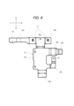
- FIG. 9 is a development view of the front surface of the sensor FPC 73.
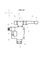
- FIG. 10 is a development view of the rear surface of the sensor FPC 73.
- FIG. 11 is a cross-sectional view of the first wiring layer 73L1 as viewed from the front surface side of the sensor FPC 73.
- FIG. 12 is a cross-sectional view of the second wiring layer 73L2 as viewed from the front surface side of the sensor FPC 73.
- FIG. 13 is a perspective view of the main part near the sensor FPC 73 as viewed from above and diagonally from the front right direction.
- FIG. 14 is a perspective view of the main parts near the sensor FPC 73 as viewed from above and diagonally rear left.
- the inhalation device is a device that generates a substance to be inhaled by a user.
- the substance generated by the inhalation device is described as an aerosol.
- the substance generated by the inhalation device may be a gas.
- FIG. 1 is a schematic diagram showing a first configuration example of an inhalation device.
- an inhalation device 100A includes a power supply unit 110, a cartridge 120, and a flavor imparting cartridge 130.
- the power supply unit 110 includes a power supply section 111A, a sensor section 112A, a notification section 113A, a memory section 114A, a communication section 115A, and a control section 116A.
- the cartridge 120 includes a heating section 121A, a liquid guiding section 122, and a liquid storage section 123.
- the flavor imparting cartridge 130 includes a flavor source 131 and a mouthpiece 124.
- An air flow path 180 is formed in the cartridge 120 and the flavor imparting cartridge 130.
- the power supply unit 111A stores power.
- the power supply unit 111A supplies power to each component of the suction device 100A under the control of the control unit 116A.
- the power supply unit 111A may be configured, for example, by a rechargeable battery such as a lithium ion secondary battery.
- the sensor unit 112A acquires various information related to the suction device 100A.
- the sensor unit 112A is configured with a pressure sensor such as a condenser microphone, a flow rate sensor, or a temperature sensor, and acquires values associated with suction by the user.
- the sensor unit 112A is configured with an input device such as a button or switch that accepts information input from the user.
- the notification unit 113A notifies the user of information.
- the information that the notification unit 113A notifies the user includes various information such as the SOC (State Of Charge) indicating the charging state of the power supply unit 111A, the pre-heating time for inhalation, and the period during which inhalation is possible.
- the notification unit 113A is composed of, for example, a light-emitting device that emits light, a display device that displays images, a sound output device that outputs sound, or a vibration device that vibrates.
- the storage unit 114A stores various information for the operation of the suction device 100A.
- the storage unit 114A is configured, for example, with a non-volatile storage medium such as a flash memory.
- the communication unit 115A is a communication interface capable of performing communication conforming to any wired or wireless communication standard.
- Such communication standards may include, for example, standards using Wi-Fi (registered trademark), Bluetooth (registered trademark), BLE (Bluetooth Low Energy (registered trademark)), NFC (Near Field Communication), or LPWA (Low Power Wide Area).
- the control unit 116A functions as an arithmetic processing unit and a control unit, and controls the overall operation of the suction device 100A in accordance with various programs.
- the control unit 116A is realized by an electronic circuit such as a CPU (Central Processing Unit) or a microprocessor.
- the liquid storage unit 123 stores the aerosol source.
- the aerosol source is atomized to generate an aerosol.
- the aerosol source is, for example, a liquid such as a polyhydric alcohol such as glycerin and propylene glycol, or water.
- the aerosol source may contain a tobacco-derived or non-tobacco-derived flavor component. If the inhalation device 100A is a medical inhaler such as a nebulizer, the aerosol source may contain a medicine.
- the liquid guide section 122 guides and holds the aerosol source, which is a liquid stored in the liquid storage section 123, from the liquid storage section 123.
- the liquid guide section 122 is, for example, a wick formed by twisting a fiber material such as glass fiber or a porous material such as porous ceramic. In this case, the aerosol source stored in the liquid storage section 123 is guided by the capillary effect of the wick.
- the heating unit 121A generates aerosol by heating the aerosol source and atomizing the aerosol source.
- the heating unit 121A is configured as a coil and is wound around the liquid guide unit 122.
- the heating unit 121A generates heat, the aerosol source held in the liquid guide unit 122 is heated and atomized, and an aerosol is generated.
- the heating unit 121A generates heat when power is supplied from the power supply unit 111A.
- the sensor unit 112A detects that the user has started inhaling and/or that predetermined information has been input, power may be supplied to the heating unit 121A.
- the flavor source 131 is a component for imparting flavor components to the aerosol.
- the flavor source 131 may contain tobacco-derived or non-tobacco-derived flavor components.
- the air flow path 180 is a flow path for air inhaled by the user.
- the air flow path 180 has a tubular structure with an air inlet hole 181, which is an entrance of air into the air flow path 180, and an air outlet hole 182, which is an exit of air from the air flow path 180, at both ends.
- the liquid guide section 122 is arranged on the upstream side (the side closer to the air inlet hole 181), and the flavor source 131 is arranged on the downstream side (the side closer to the air outlet hole 182).
- the air flowing in from the air inlet hole 181 as the user inhales is mixed with the aerosol generated by the heating section 121A, and as shown by the arrow 190, is transported through the flavor source 131 to the air outlet hole 182.
- the flavor components contained in the flavor source 131 are imparted to the aerosol.
- the mouthpiece 124 is a member that is held by the user when inhaling.
- An air outlet hole 182 is arranged in the mouthpiece 124.
- the configuration of the suction device 100A is not limited to the above, and various configurations such as those shown below are possible.
- the inhalation device 100A may not include a flavoring cartridge 130.
- the cartridge 120 is provided with a mouthpiece 124.
- the suction device 100A may include multiple types of aerosol sources. Multiple types of aerosols generated from the multiple types of aerosol sources may be mixed in the air flow path 180 and undergo a chemical reaction to generate further types of aerosols.
- the means for atomizing the aerosol source is not limited to heating by the heating unit 121A.
- the means for atomizing the aerosol source may be vibration atomization or induction heating.
- FIG. 2 is a schematic diagram showing a second configuration example of the suction device.
- the suction device 100B according to this configuration example includes a power supply unit 111B, a sensor unit 112B, a notification unit 113B, a memory unit 114B, a communication unit 115B, a control unit 116B, a heating unit 121B, a storage unit 140, and a heat insulating unit 144.
- the power supply unit 110 that stores the power supply unit 111A and the heating unit 121A are separate, but in the suction device 100B according to the second configuration example, the power supply unit 111B and the heating unit 121B are integrated. That is, the suction device 100B according to the second configuration example can also be said to be a power supply unit with a built-in heating unit.
- Each of the power supply unit 111B, the sensor unit 112B, the notification unit 113B, the memory unit 114B, the communication unit 115B, and the control unit 116B is substantially the same as the corresponding components included in the suction device 100A according to the first configuration example.
- the storage section 140 has an internal space 141 and holds the stick-shaped substrate 150 while storing a part of the stick-shaped substrate 150 in the internal space 141.
- the storage section 140 has an opening 142 that connects the internal space 141 to the outside, and stores the stick-shaped substrate 150 inserted into the internal space 141 through the opening 142.
- the storage section 140 is a cylindrical body with the opening 142 and the bottom 143 as the bottom surface, and defines a columnar internal space 141.
- An air flow path that supplies air to the internal space 141 is connected to the storage section 140.
- An air inlet hole which is an air inlet to the air flow path, is arranged, for example, on the side of the suction device 100.
- An air outlet hole which is an air outlet from the air flow path to the internal space 141, is arranged, for example, on the bottom 143.
- the stick-type substrate 150 When the stick-type substrate 150 is held in the storage portion 140, at least a part of the substrate portion 151 is stored in the internal space 141, and at least a part of the mouthpiece portion 152 protrudes from the opening 142.
- the heating section 121B is configured in a film shape and is arranged to cover the outer periphery of the storage section 140.
- the heating section 121B generates heat, the substrate section 151 of the stick-shaped substrate 150 is heated from the outer periphery, and an aerosol is generated.
- the insulating section 144 prevents heat transfer from the heating section 121B to other components.
- the insulating section 144 is made of a vacuum insulating material or an aerogel insulating material.
- the configuration of the suction device 100B is not limited to the above, and various configurations such as those shown below are possible.
- the heating section 121B may be configured in a blade shape and disposed so as to protrude from the bottom 143 of the storage section 140 into the internal space 141. In that case, the blade-shaped heating section 121B is inserted into the substrate section 151 of the stick-shaped substrate 150 and heats the substrate section 151 of the stick-shaped substrate 150 from the inside. As another example, the heating section 121B may be disposed so as to cover the bottom 143 of the storage section 140. Furthermore, the heating section 121B may be configured as a combination of two or more of a first heating section that covers the outer periphery of the storage section 140, a blade-shaped second heating section, and a third heating section that covers the bottom 143 of the storage section 140.
- the storage unit 140 may include an opening/closing mechanism, such as a hinge, that opens and closes a portion of the outer shell that forms the internal space 141. The storage unit 140 may then open and close the outer shell to accommodate the stick-shaped substrate 150 inserted into the internal space 141 while clamping it.
- the heating unit 121B may be provided at the clamping location in the storage unit 140, and may heat the stick-shaped substrate 150 while pressing it.
- the means for atomizing the aerosol source is not limited to heating by the heating unit 121B.
- the means for atomizing the aerosol source may be induction heating.
- the suction device 100B has at least an electromagnetic induction source such as a coil that generates a magnetic field, instead of the heating unit 121B.
- a susceptor that generates heat by induction heating may be provided in the suction device 100B, or may be included in the stick-shaped substrate 150.
- suction device 100 an embodiment of a suction device (hereinafter, referred to as suction device 100) in which the configuration of the suction device disclosed herein is applied to the suction device 100B of the second configuration example described above will be described. Note that, although a specific description will be omitted, a part of the configuration of the suction device 100 described in detail below can also be applied to the suction device 100A of the first configuration example.
- Figure 3 is an overall perspective view of the suction device 100.
- the direction in which the stick-shaped substrate 150 is inserted into and removed from the suction device 100 is defined as the up-down direction
- the direction in which the shutter 23, which will be described later, slides is defined as the front-rear direction
- the direction perpendicular to the up-down direction and the front-rear direction is defined as the left-right direction.
- the front is defined as Fr, the rear as Rr, the left side as L, the right side as R, the top as U, and the bottom as D.
- the suction device 100 is preferably sized to fit in the hand, and has, for example, a rod shape.
- a user holds the suction device 100 in one hand with the fingertips in contact with the surface of the suction device 100.
- the shape of the suction device 100 is not limited to a rod shape, and can be any shape (for example, a rounded, approximately rectangular parallelepiped shape or an egg shape).
- the suction device 100 comprises an internal unit 10 (see Figures 4 to 6) and a case 20 that constitutes the exterior of the suction device 100.
- the case 20 has a lower case 21 and an upper case 22. A portion of the internal unit 10 is housed in the lower case 21, and the entire internal unit 10 is housed in the case 20 by placing the upper case 22 over the lower case 21 from above.
- the top surface of the suction device 100 is provided with an opening 27 (see Figures 4 to 6) through which the stick-shaped substrate 150 is inserted and removed, and a shutter 23 that can slide back and forth.
- the opening 27 is located at the rear side of the top surface of the suction device 100.
- the shutter 23 selectively takes an open state (front position) that opens the opening 27 to allow the stick-shaped substrate 150 to be inserted and removed, and a closed state (rear position) that positions the shutter 23 above the opening 27 to close the opening 27.
- the user opens the shutter 23.
- a shutter detection sensor 11 (see FIG. 4) is provided near the shutter 23.
- the shutter detection sensor 11 detects whether the shutter 23 is open or not.
- the shutter detection sensor 11 is an example of the sensor unit 112B of the suction device 100B in FIG. 2.
- a USB (Universal Serial Bus) port 26 (see FIG. 4) is provided on the top surface of the suction device 100, adjacent to the opening 27.
- the shutter 23 blocks the USB port 26.
- the USB port 26 is open.
- the USB port 26 is configured to be electrically connectable to an external power source (not shown) capable of supplying power for charging the power supply unit 111C (see FIG. 4).
- the USB port 26 is, for example, a receptacle into which a mating plug can be inserted.
- the USB port 26 is a USB Type-C shaped receptacle.
- the suction device 100 has an operation unit 24 and a light-emitting unit 25 on the front side.
- the operation unit 24 is disposed below the light-emitting unit 25. More specifically, the operation unit 24 and the light-emitting unit 25 are components of the internal unit 10 housed in the case 20, and are configured such that a portion of the operation unit 24 and the light-emitting unit 25 are exposed from an opening formed on the front side of the case 20.
- the light-emitting unit 25 is an example of the notification unit 113B of the suction device 100B in FIG. 2.
- the operation unit 24 is a button-type switch that can be operated by the user, and is an input device that accepts information input from the user.
- the operation unit 24 is connected to the main board 50 (see Figures 4 to 6) described below.
- the MCU (Micro Controller Unit) 1 (see Figures 4 to 6) or the heating unit 121C (see Figure 7) is started.
- the MCU 1 functions as the control unit 116B in the suction device 100B.
- the MCU 1 may also have an integrated function as the communication unit 115B in addition to the function as the control unit 116B in the suction device 100B.
- the MCU 1 may be composed of one IC or two or more ICs.
- the discharge control to the heating unit 121C and the charge control to the power supply unit 111C may be performed by one IC or by separate ICs.
- the light-emitting unit 25 is composed of light-emitting elements such as LEDs (Light Emitting Diodes).
- the light-emitting unit 25 has a plurality of LEDs 251 (see FIG. 6) provided on the main board 50, and a transparent cover 250 that covers the plurality of LEDs 251 and transmits light from the LEDs 251. A portion of the transparent cover 250 is exposed from an opening formed on the front surface of the case 20.
- the plurality of LEDs 251 are configured to be capable of emitting light in a plurality of colors including blue, yellow, and red.
- the number of light-emitting elements can be set arbitrarily, and for example, the light-emitting unit 25 may have only one light-emitting element.
- the light emitting unit 25 emits light in a predetermined light emission manner in response to a command from the MCU 1, and notifies the user of predetermined information.
- the light emission manner can be, for example, the light emission color, but is not limited to this, and can be, for example, the strength of the lighting intensity (in other words, brightness), or the lighting pattern (for example, blinking at a predetermined time interval), etc.
- the predetermined information is, for example, operational information indicating whether the power of the suction device 100 is on or not.
- Figure 4 is a perspective view of the internal unit 10 seen from the front right side
- Figure 5 is a perspective view of the internal unit 10 seen from the front left side
- Figure 6 is an exploded perspective view of the internal unit 10
- Figure 7 is a cross-sectional perspective view of the heater assembly 30
- Figure 8 is a block diagram simply showing the electrical connections of the main elements of the internal unit 10.
- the internal unit 10 is the suction device 100 with the case 20 and shutter 23 removed.
- the internal unit 10 includes a chassis 40, a main board 50, a vibration device 60, a heater assembly 30, a power supply unit 111C, a power supply board 71, a peripheral FPC 72, a sensor FPC 73, and various sensors.
- the peripheral FPC 72 and the sensor FPC 73 are flexible circuit boards. Flexible circuit boards are flexible, contain conductive wiring and/or signal wiring, and can mount electronic components (elements) such as resistors and chips. Flexible circuit boards generally have a thickness of 100 ⁇ m to 600 ⁇ m.
- the power supply board 71 may be a flexible circuit board, a rigid board (described later), or a combination of a flexible board and a rigid board, but a flexible circuit board will be used as an example here.
- the chassis 40 has a power supply holding portion 41 that holds the power supply unit 111C, a board holding portion 42 that holds the main board 50, and a heater holding portion 43 that holds the heater assembly 30.
- the power supply holding portion 41 is located in the lower part of the chassis 40, and the board holding portion 42 and the heater holding portion 43 are located in the upper part of the chassis 40.
- the power supply holding section 41 has a cylindrical shape with a portion of the side cut out, in other words, a roughly semi-cylindrical shape.
- the power supply holding section 41 has a bottom wall section 401, a side wall section 402 having an arc shape and standing upward from the bottom wall section 401, and an upper wall section 403 provided at the upper end section of the side wall section 402.
- the power supply section 111C is disposed in a space surrounded by the bottom wall section 401, the side wall section 402, and the upper wall section 403.
- the board holding portion 42 is provided on a vertical wall portion 404 that stands upward from the upper wall portion 403 of the power supply holding portion 41.
- the board holding portion 42 is provided on one side (here, the front side) of the vertical wall portion 404 in the front-to-rear direction, and holds the main board 50.
- the heater holding portion 43 is provided on the opposite side (here, the rear side) of the vertical wall portion 404 from the substrate holding portion 42 in the front-rear direction.
- the heater holding portion 43 has a space surrounded by the vertical wall portion 404, a pair of left and right wall portions 405 extending in the front-rear direction from the vertical wall portion 404, and the upper surface of the upper wall portion 403 of the power supply holding portion 41, and the heater assembly 30 is disposed in this space.
- the main board 50 is a rigid board on which a plurality of electronic components (elements) are mounted on both sides. Rigid boards are not flexible and generally have a thickness of 300 ⁇ m to 1,600 ⁇ m.
- the main board 50 is mounted with an MCU 1, an LED 251, a charging IC (Integrated Circuit) 81, a step-up DC/DC converter 82, and the like.
- the main board 50 is held by the board holder 42 of the chassis 40 so that the element mounting surface faces the front-rear direction. In FIG. 6, only the front surface 501 (here, the front surface) of the main board 50 is shown. Therefore, the charging IC 81 and the step-up DC/DC converter 82 mounted on the back surface 502 (here, the rear surface) are not shown.
- a power supply connection section 51 that electrically connects to the power supply section 111C is provided in the lower region of the surface 501 of the main board 50.
- the power supply connection section 51 is electrically connected to the power supply section 111C via the board connection section 710 of the power supply board 71.
- the power supply section 111C is a cylindrical lithium ion secondary battery, and is an example of the power supply section 111B of the suction device 100B in FIG. 2.
- the power supply unit 111C is provided with a positive electrode tab 111a and a negative electrode tab 111b.
- the power supply unit 111C is arranged in the power supply holding portion 41 of the chassis 40 with the positive electrode tab 111a and the negative electrode tab 111b arranged forward.
- the power supply board 71 is arranged in front of the power supply unit 111C and the main board 50 and extends in the vertical direction. Also referring to FIG.
- the positive electrode tab connection portion 711a and the negative electrode tab connection portion 711b of the power supply board 71 are connected to the positive electrode tab 111a and the negative electrode tab 111b of the power supply unit 111C, respectively, and the board connection portion 710 is electrically connected to the power supply connection portion 51 of the main board 50.
- the power of the power supply unit 111C is transmitted to the main board 50 through the conductive track formed on the power supply board 71 and is supplied to each electronic component, for example, the step-up DC/DC converter 82.
- the power supply board 71 is also provided with a power supply temperature sensor 16.
- the power supply temperature sensor 16 is a sensor that detects the temperature of the power supply unit 111C.
- the power supply temperature sensor 16 is, for example, a thermistor.
- the power supply temperature sensor 16 is an example of the sensor unit 112B of the suction device 100B in FIG. 2.
- a USB port 26 is provided in the upper region of the back surface 502 of the main board 50.
- the USB port 26 is electrically connected to the charging IC 81 by wiring formed on the main board 50.
- the rear surface 502 of the main board 50 is provided with a charging IC 81, a step-up DC/DC converter 82, and heater connections 57a, 57b.
- the charging IC 81 performs charging control to supply (charge) the power input from the USB port 26 to the power supply unit 111C.
- the step-up DC/DC converter 82 boosts the power supplied from the power supply unit 111C to generate power to be supplied to the heating unit 121C via the heating switch 85.
- the heating switch 85 is, for example, a FET (Field Effect Transistor).
- the heater connectors 57a and 57b are connected to the board connector 121a extending from below the heater assembly 30, and supply power to the heating section 121C of the heater assembly 30. This allows power to be supplied from the power supply section 111C to the heating section 121C of the heater assembly 30 via the main board 50.
- the vibration device 60 is composed of a vibration element such as a vibration motor. As shown in FIG. 6, the vibration device 60 is disposed between the upper surface of the power supply unit 111C and the upper wall unit 403 in the power supply holding unit 41 of the chassis 40. The lead wire 61 of the vibration device 60 is connected to the peripheral FPC 72.
- the vibration device 60 vibrates in a predetermined vibration mode in response to a command from the MCU 1 to notify the user of predetermined information. For example, when the heating of the stick-type substrate 150 starts or ends, the vibration device 60 vibrates in a predetermined vibration mode to notify the user of the start or end of heating.
- the vibration device 60 is an example of the notification unit 113B of the suction device 100B in FIG. 2.
- the heater assembly 30 includes a heating section 121C, a housing section 140C, and a heat insulating section 144C.
- the heating section 121C is, for example, a film heater, and is wound around the outer periphery of the housing section 140C.
- the heating section 121C and the board connection section 121a may be formed of a single heater FPC.
- the heater assembly 30 is also provided with a stick guide 31.
- the stick guide 31 is provided on the upper part of the heater assembly 30 and guides the insertion and removal of the stick-shaped substrate 150 into the storage section 140C.
- the stick guide 31 is a cylindrical member that has an opening 27 and constitutes part of the storage section 140C.
- the heater assembly 30 is also provided with a heater temperature sensor 15 capable of detecting the temperature of the heating section 121C. More specifically, the heater temperature sensor 15 is provided between the heating section 121C and the insulating section 144C, in contact with or in close proximity to the heating section 121C.
- the heater temperature sensor 15 is, for example, a thermistor.
- the sensor FPC 73 is disposed between the standing wall portion 404 of the heater holding portion 43 and the heater assembly 30.
- One or more sensors are mounted or electrically connected to the sensor FPC 73.
- the sensor FPC 73 is equipped with a stick detection sensor 12, a suction sensor 13, and a case temperature sensor 14.
- the stick detection sensor 12, the suction sensor 13, and the case temperature sensor 14 are examples of the sensor unit 112B of the suction device 100B in FIG. 2.
- the stick detection sensor 12 is a sensor capable of detecting the stick-shaped substrate 150 housed in the housing section 140.
- the stick detection sensor 12 is an optical sensor capable of detecting the stick-shaped substrate 150 based on the amount of reflected light of light irradiated onto the housing section 140.
- the amount of light is a concept that includes luminous flux, illuminance, luminous flux emittance, luminous intensity, brightness, etc.
- the optical sensor is, for example, an IR (Infrared Rays) sensor.
- the suction sensor 13 is a sensor that detects the user's puffing action (inhalation action).
- the suction sensor 13 is composed of, for example, a condenser microphone, a pressure sensor, a puff thermistor, etc.
- the suction sensor 13 is provided near the stick guide 31 on the sensor FPC 73.
- the case temperature sensor 14 is a sensor that detects the temperature of the case 20.
- the case temperature sensor 14 is, for example, a thermistor.
- the case temperature sensor 14 is arranged adjacent to the inner surface of the case 20 on the sensor FPC 73.
- the sensor FPC 73 is also provided with a heater temperature sensor connection 731 that connects to the heater temperature sensor 15 of the heater assembly 30.
- the heater temperature sensor connection 731 is provided on the lower part of the sensor FPC 73. More specifically, a lead wire 15a is connected to the heater temperature sensor 15, and the heater temperature sensor connection 731 connects to the lead wire 15a extending from below the heater assembly 30.
- the stick detection sensor 12, suction sensor 13, case temperature sensor 14, and heater temperature sensor connection part 731 are connected to the board connection part 730 via signal wiring formed on the sensor FPC 73.
- the board connection part 730 is connected to the sensor FPC connection part 55 provided in the central area of the surface 501 of the main board 50. This allows the detection results of each sensor to be output to the MCU 1 mounted on the main board 50.
- the sensor FPC 73 will be explained in more detail later.
- the MCU1 starts heating the heating unit 121C.
- aerosol is supplied into the user's mouth from the aerosol source of the stick-shaped substrate 150 heated by the heating unit 121C.
- the suction sensor 13 detects the number of suctions, and the MCU1 stops heating after a predetermined number of suctions or after a predetermined time has elapsed.
- the suction device 100 While the suction device 100 is heating, the case temperature sensor 14, heater temperature sensor 15, and power supply temperature sensor 16 detect the respective temperatures, and if abnormal heating is determined, the MCU1 stops or suppresses heating of the heating unit 121C.
- the user can operate the operation unit 24 to, for example, check the SOC of the power supply unit 111C.
- the light-emitting unit 25 (LED 251) and the vibration device 60 notify the user of various information such as the SOC of the power supply unit 111C, error indications, etc. If the SOC of the power supply unit 111C decreases, the user can connect an external power source to the USB port 26 to charge the power supply unit 111C.
- Figure 9 is an exploded view of the front surface (rear surface side of the main body 751) of the sensor FPC 73
- Figure 10 is an exploded view of the back surface (front surface side of the main body 751) of the sensor FPC 73.
- the dashed and double-dashed lines in Figures 9 and 10 are folding lines. Note that the front and back surfaces of the sensor FPC 73 are defined merely for the sake of convenience in order to simplify and clarify the explanation, and may face in any direction in the suction device 100.
- the sensor FPC 73 has a generally rectangular main body 751 that is longer in the vertical direction than in the horizontal direction, a right upper extension 752 that extends to the right from the top of the main body 751, a right lower extension 753 that extends to the right from the bottom of the main body 751 and then bends upward, a lower extension 754 that extends further downward from the bottom of the main body 751, an upper extension 755 that extends further upward from the top of the main body 751, an upper right extension 756 that extends to the right from the upper extension 755, and an upper left extension 757 that extends to the left from the upper extension 755.
- the upper left extension 757 is longer than the upper right extension 756, and is configured so that the tip (left end) of the upper left extension 757 faces the main body 751 when the sensor FPC 73 is folded and stored in the case 20 (hereinafter, the stored state) as shown in FIG. 6.
- the sensor FPC 73 is equipped with the stick detection sensor 12, suction sensor 13, and case temperature sensor 14, and is connected to the sensor FPC connection part 55 of the main board 50 by the board connection part 730. More specifically, the stick detection sensor 12, suction sensor 13, and case temperature sensor 14 are mounted on the surface of the sensor FPC 73 (the surface that forms the rear surface of the main body part 751) as shown in FIG. 9.
- the stick detection sensors 12 are arranged at approximately symmetrical positions on either side of the upper extension 755, one on the upper right extension 756 and one on the upper left extension 757.
- the stick detection sensors 12 are arranged on the outer periphery of the stick guide 31 in the stored state, and detect the stick-shaped substrate 150 stored in the storage section 140.
- the suction sensor 13 is located at the tip (left end) of the upper left extension 757.
- the suction sensor 13 is located on the outer periphery of the stick guide 31 in the stored state, and detects pressure changes and temperature changes of the air flowing from near the opening 27 to the storage section 140 in conjunction with the puffing action (suction action).
- the case temperature sensor 14 is located at the tip (upper end) of the lower right extension 753. When housed, the case temperature sensor 14 is close to the wall of the case 20 and detects the temperature of the case 20. While the two stick detection sensors 12 and the suction sensor 13 are located at approximately the same position in the vertical direction (longitudinal direction of the sensor FPC), the case temperature sensor 14 is located at a different vertical position from these, that is, at the bottom in this embodiment.
- the board connection part 730 is mounted on the back surface of the sensor FPC 73 (the surface that forms the front surface of the main body part 751).
- the board connection part 730 is located at the tip (right end part) of the upper right extension part 752, that is, at a position between the vertical positions of the two stick detection sensors 12 and the suction sensor 13, and the vertical position of the case temperature sensor 14.
- the main board 50 which is a rigid board
- these sensors 12 to 14 are connected collectively to the sensor FPC connection part 55 of the main board 50 at the board connection part 730 through the signal wiring 738, 739 formed on the sensor FPC 73. Therefore, the connection parts of the sensors 12 to 14 to the main board 50 can be made common, and the main board 50, which is a rigid board, can be made smaller.
- the board connection portion 730 of the sensor FPC 73 and the sensor FPC connection portion 55 of the main board 50 are preferably connectors 19 consisting of a plug (male connector) and a receptacle (female connector). This makes the connection easier.
- the sensor FPC connection portion 55 is connected to the MCU 1 via signal wiring formed on the main board 50.
- the sensor FPC 73 is equipped with three sensors: the stick detection sensor 12, the suction sensor 13, and the case temperature sensor 14.
- other sensors may be mounted on the sensor FPC 73 in place of or in addition to these sensors, so long as one or more sensors are mounted or electrically connected to the sensor FPC 73.
- An example of the other sensor is the power supply temperature sensor 16. In other words, regardless of the type of sensor, it is sufficient that one or more sensors are mounted or electrically connected to the sensor FPC 73 and the connection to the main board 50 is shared.
- the connection to the main board 50 is made common.
- the case temperature sensor 14, which is placed at a different position in the up-down direction (longitudinal direction of the sensor FPC) relative to the two stick detection sensors 12 and the suction sensor 13 is also connected to the sensor FPC connection part 55 of the main board 50 via the board connection part 730.
- connection to the main board 50 is located between the sensor located at one end in the longitudinal direction of the sensor FPC and the sensor located at the other end.
- the board connection 730 is located between the vertical positions of the two stick detection sensors 12 and the suction sensor 13 (longitudinal direction of the sensor FPC) and the vertical position of the case temperature sensor 14 (longitudinal direction of the sensor FPC). This makes it possible to equalize the length of the signal wiring from each sensor to the board connection 730.
- the suction sensor 13 and the case temperature sensor 14 are supplied with the input voltage VCC1, which is an input voltage of the same potential. Therefore, the suction sensor 13 and the case temperature sensor 14 can be connected to the signal wiring 738 of the same potential and connected to the main board 50 by the same electrical contact 55a. In this way, by mounting sensors connected to signal wiring of the same potential on the sensor FPC 73, the same electrical contact 55a can be used in the sensor FPC connection part 55, so there is no need to provide multiple electrical contacts for each sensor in the sensor FPC connection part 55, and the main board 50 can be made smaller.
- the heater temperature sensor 15 which is connected to the sensor FPC 73 via the lead wire 15a, is supplied with the same input voltage VCC1 as the suction sensor 13 and the case temperature sensor 14, is connected to signal wiring of the same potential, and is connected to the main board 50 by the same electrical contact 55a. This allows the main board 50 to be further miniaturized.
- the two stick detection sensors 12 are also supplied with an input voltage VCC2. Therefore, the two stick detection sensors 12 are connected to the signal wiring 739 of the same potential and can be connected to the main board 50 with the same electrical contact 55b.
- the input voltage VCC2 of the two stick detection sensors 12 and the input voltage VCC1 of the suction sensor 13 and the case temperature sensor 14 can be the same or different.
- the electrical contacts 55a and 55b can be common or different.
- the electrical contacts 55a and 55b must be different. In this way, even if the sensors have different input voltages, by making the electrical contacts different, they can be mounted on the sensor FPC 73 and the connection to the main board 50 can be common.
- the sensor FPC 73 is a laminated wiring board in which a first wiring layer 73L1 and a second wiring layer 73L2 are laminated.
- FIG. 11 is a cross-sectional view of the first wiring layer 73L1 as viewed from the front side of the sensor FPC 73 (the rear side of the main body 751)
- FIG. 12 is a cross-sectional view of the second wiring layer 73L2 as viewed from the front side of the sensor FPC 73 (the rear side of the main body 751).
- the first wiring layer 73L1 and the second wiring layer 73L2 are stacked in the sensor FPC 73 such that the first wiring layer 73L1 is closer to the back side (the front side of the main body 751) than the second wiring layer 73L2, and the second wiring layer 73L2 is closer to the front side (the rear side of the main body 751) than the first wiring layer 73L1.
- the sensor FPC 73 is folded along the folding lines shown by the dashed and double-dashed lines in Figures 9 and 10.
- the sensor FPC 73 is folded along the folding lines shown by the dashed and double-dashed lines in FIGS. 9 and 10, and has a case facing area 73A that faces the case 20.
- the case facing area 73A of the sensor FPC 73 has a first case facing area 73A1 which is the area to the left of the fold line in the upper right extension 752, a second case facing area 73A2 which is the area of the lower right extension 753, a third case facing area 73A3 which is the area of the upper right extension 756, and a fourth case facing area 73A4 which is the area of the upper left extension 757.
- the front side (the rear side of the main body 751) faces the case 20
- the back side (the front side of the main body 751) faces the case 20
- the back side (the front side of the main body 751) faces the case 20.
- printed wiring 732 including signal wiring 733 and ground wiring 734 is formed on the first wiring layer 73L1 and the second wiring layer 73L2.
- the printed wiring 732 is formed from a thin metal film of a conductive material.
- the printed wiring 732 is formed from a thin copper film.
- metals used as conductive materials, including copper have a higher thermal conductivity than resins, etc.
- At least a portion of the ground wiring 734 formed in the first wiring layer 73L1 and the second wiring layer 73L2 is formed in a mesh shape. In this embodiment, it is formed in a diagonal lattice mesh shape.
- the mesh shape of the ground wiring 734 may be a hexagonal honeycomb mesh shape, a rectangular mesh shape, or a mesh shape with many circles cut out.
- the signal wiring 733 formed in the first wiring layer 73L1 and the second wiring layer 73L2 constitutes the signal wiring 738 and the signal wiring 739 described above.
- the signal wiring 733 formed in the first wiring layer 73L1 and the second wiring layer 73L2 has a first signal wiring 733a that connects the board connection portion 730 and the stick detection sensor 12, a second signal wiring 733b that connects the board connection portion 730 and the suction sensor 13, a third signal wiring 733c that connects the board connection portion 730 and the case temperature sensor 14, and a fourth signal wiring 733d that connects the board connection portion 730 and the heater temperature sensor connection portion 731.
- the first signal wiring 733a runs from the board connection portion 730 through the upper right extension portion 752, the main body portion 751, and the upper extension portion 755, and then through the upper right extension portion 756 or the upper left extension portion 757 to connect to each of the two stick detection sensors 12.
- the second signal wiring 733b connects from the board connection portion 730 through the upper right extension portion 752, the main body portion 751, the upper extension portion 755, and the upper left extension portion 757 to the suction sensor 13.
- the third signal wiring 733c runs from the board connection portion 730 through the upper right extension portion 752, near the right end of the main body portion 751, and the lower right extension portion 753 to connect to the case temperature sensor 14.
- the fourth signal wiring 733d runs from the board connection portion 730 through the upper right extension portion 752, near the right end of the main body portion 751, and the lower extension portion 754 to connect to the heater temperature sensor connection portion 731.
- the first signal wiring 733a to the fourth signal wiring 733d are formed in the first wiring layer 73L1 and the second wiring layer 73L2, and the first signal wiring 733a to the fourth signal wiring 733d of the first wiring layer 73L1 and the first signal wiring 733a to the fourth signal wiring 733d of the second wiring layer 73L2 are connected through vias.
- the wiring area of the signal wiring 733 formed in the layer closer to the case 20 of the first wiring layer 73L1 and the second wiring layer 73L2 is smaller than the wiring area of the signal wiring 733 formed in the layer farther from the case 20.
- the wiring area of the signal wiring 733 formed in the second wiring layer 73L2 which is closer to the case 20, of the first wiring layer 73L1 and the second wiring layer 73L2 is smaller than the wiring area of the signal wiring 733 formed in the first wiring layer 73L1, which is farther from the case 20.
- the wiring area of the signal wiring 733 formed in the first wiring layer 73L1, which is closer to the case 20, of the first wiring layer 73L1 and the second wiring layer 73L2, is smaller than the wiring area of the signal wiring 733 formed in the second wiring layer 73L2, which is farther from the case 20.
- the wiring area of the signal wiring 733 formed in the first wiring layer 73L1, which is closer to the case 20, of the first wiring layer 73L1 and the second wiring layer 73L2 is smaller than the wiring area of the signal wiring 733 formed in the second wiring layer 73L2, which is farther from the case 20.
- the sensor FPC 73 can prevent the external noise such as static electricity from entering the signal wiring 733. This prevents external noise such as static electricity from flowing through the signal wiring 733 and causing the sensors 12 to 14 mounted on the sensor FPC 73 to misdetect or break down due to the external noise, improving the durability of the suction device 100 and the power supply unit 110.
- the stick detection sensor 12, suction sensor 13, and case temperature sensor 14 are all mounted on the surface of the sensor FPC 73 that is farther from the case 20, which in this embodiment is the back surface of the sensor FPC 73.
- the detection accuracy of the stick detection sensor 12 is improved, and it is possible to more accurately detect whether the stick-shaped substrate 150 is contained in the container 140.
- the MCU 1 mounted on the main board 50 controls the suction device 100 based on the detection results of these sensors 12 to 14.
- the ground wiring 734 is formed in the layer of the first wiring layer 73L1 and the second wiring layer 73L2 that is closer to the case 20 in the area overlapping with the sensors 12 to 14.
- the ground wiring 734 is formed in the first wiring layer 73L1, which is closer to the case 20 in the area overlapping with the stick detection sensor 12, of the first wiring layer 73L1 and the second wiring layer 73L2 in the sensor FPC 73.
- the ground wiring 734 is formed in the first wiring layer 73L1, which is closer to the case 20 in the area overlapping with the suction sensor 13, of the first wiring layer 73L1 and the second wiring layer 73L2 in the sensor FPC 73.
- the ground wiring 734 is formed in the first wiring layer 73L1, which is closer to the case 20 in the area overlapping with the case temperature sensor 14, of the first wiring layer 73L1 and the second wiring layer 73L2 in the sensor FPC 73.
- the first wiring layer 73L1 which is the layer closer to the case 20 in the area overlapping with the suction sensor 13, does not have signal wiring formed within a predetermined area 73B1 that includes the area overlapping with the suction sensor 13.
- the predetermined area 73B1 is the area to the left of the bending line formed in the upper left extension portion 757 at a position approximately symmetrical to the right end of the upper right extension portion 756 across the upper extension portion 755.
- the first wiring layer 73L1 which is the layer closer to the case 20 in the area overlapping with the case temperature sensor 14, does not have a signal wiring 733 formed in a predetermined area 73B2 that includes the area overlapping with the case temperature sensor 14.
- the predetermined area 73B2 is the lower right extension 753.
- the external noise such as static electricity can be more reliably released to the ground wiring 734 formed in the layer closer to the case 20 in the area overlapping with the suction sensor 13 and the case temperature sensor 14, and external noise such as static electricity can be more reliably prevented from entering the signal wiring 733 (second signal wiring 733b and third signal wiring 733c) connected to the suction sensor 13 and the case temperature sensor 14, thereby more reliably preventing external noise such as static electricity from entering the suction sensor 13 and the case temperature sensor 14 and causing false detection or failure of the suction sensor 13 and the case temperature sensor 14.
- the sensor FPC 73 is bent so that the two stick detection sensors 12 are away from the case 20, and the upper extension 755, upper right extension 756, and upper left extension 757 surround the stick guide 31.
- At least a portion of the area of the case 20 facing the sensor FPC 73 may be covered with a metal or insulating film.
- the positions of the stick detection sensor 12, suction sensor 13, and case temperature sensor 14 on the sensor FPC 73 are not limited to these and can be changed as appropriate.
- the inhalation device 100A may further include a heating unit that heats the flavor source 131 in addition to the heating unit 121A.
- a power source capable of supplying power to a heating unit (heating unit 121A to 121C) that heats at least one of an aerosol source (stick-type substrate 150) and a flavor source (flavor source 131);
- a flexible printed circuit board (sensor FPC 73) on which one or more sensors (a stick detection sensor 12, a suction sensor 13, a case temperature sensor 14) are mounted or electrically connected; a case (case 20) that accommodates the power supply and the flexible printed wiring board;
- a power supply unit (power supply unit 110) of an aerosol generating device (inhalation device 100, 100A, 100B) comprising:
- the flexible printed wiring board has a first wiring layer (first wiring layer 73L1) and a second wiring layer (second wiring layer 73L2) laminated thereon,
- a signal wiring (signal wiring 733) is formed in at least one of the first wiring layer and the second wiring layer, In a case facing region (case facing region 73A) of the flexible printed wiring board facing the case
- the flexible printed circuit board can prevent the external noise such as static electricity from entering the signal wiring. This prevents external noise such as static electricity from flowing through the signal wiring and prevents the sensor mounted on the flexible printed circuit board from false detection or failure due to the external noise, improving the durability of the power supply unit of the aerosol generating device.
- a power supply unit for the aerosol generating device The sensor is mounted on a surface of the flexible printed circuit board that is farther from the case. Power supply unit for the aerosol generator.
- the flexible printed wiring board can prevent external noise such as static electricity from entering the sensor, which can cause the sensor to make false detections or break down.
- a power supply unit for the aerosol generating device In the flexible printed wiring board, a ground wiring (ground wiring 734) is formed in the layer of the first wiring layer and the second wiring layer that is closer to the case in the area overlapping with the sensor. Power supply unit for the aerosol generator.
- the external noise such as static electricity can be released to the ground wiring formed in the layer closer to the case in the area overlapping with the sensor, thereby further preventing external noise such as static electricity from entering the sensor and causing false detection or failure of the sensor.
- a power supply unit for the aerosol generating device In the flexible printed wiring board, the signal wiring is not formed in a layer of the first wiring layer and the second wiring layer that is closer to the case than the area overlapping with the sensor, within a predetermined area including the area overlapping with the sensor. Power supply unit for the aerosol generator.
- the external noise such as static electricity can be more reliably released to the ground wiring formed in the layer closer to the case in the area overlapping with the sensor, and the external noise such as static electricity can be more effectively prevented from entering the signal wiring connected to the sensor, thereby more effectively preventing external noise such as static electricity from entering the sensor and causing false detection or failure of the sensor.
- a power supply unit for the aerosol generating device according to any one of (1) to (4),
- the sensor is a temperature sensor (case temperature sensor 14).
- a power supply unit for the aerosol generating device according to any one of (1) to (4),
- the sensor is an optical sensor (stick detection sensor 12).
- a power supply unit for the aerosol generating device is The flexible printed wiring board is The optical sensor is bent away from the case. Power supply unit for the aerosol generator.
- the optical sensor can be placed farther away from the case, which can better prevent external noise such as static electricity from entering the optical sensor and causing false detection or failure of the optical sensor.
- a power supply unit for the aerosol generating device according to any one of (1) to (7),
- the aerosol generating device further includes a controller (MCU1) for controlling the aerosol generating device, The controller controls the aerosol generating device based on the detection result of the sensor.
- Power supply unit for the aerosol generator for the aerosol generator.
- a power supply unit for the aerosol generating device according to any one of (1) to (8), At least a part of the area of the case facing the flexible printed wiring board is covered with a metal or insulating film. Power supply unit for the aerosol generator.
- a heating section for heating at least one of the aerosol source (the stick-shaped substrate 150) and the flavor source (the flavor source 131);
- a power source power source unit 111A to 111C capable of supplying power to the heating unit;
- a flexible printed circuit board (sensor FPC 73) on which one or more sensors (a stick detection sensor 12, a suction sensor 13, a case temperature sensor 14) are mounted or electrically connected; a case (case 20) that accommodates the heating unit, the power source, and the flexible printed wiring board;
- An aerosol generating device (inhalation device 100, 100A, 100B) comprising:
- the flexible printed wiring board has a first wiring layer (first wiring layer 73L1) and a second wiring layer (second wiring layer 73L2) laminated thereon,
- a signal wiring (signal wiring 733) is formed in at least one of the first wiring layer and the second wiring layer, In a case facing region (case facing region 73A) of the flexible printed wiring board facing the case, a wiring
- the flexible printed circuit board can prevent the external noise such as static electricity from entering the signal wiring. This prevents external noise such as static electricity from flowing through the signal wiring and prevents the sensor mounted on the flexible printed circuit board from false detection or failure due to external noise, improving the durability of the aerosol generating device.
Landscapes
- Physics & Mathematics (AREA)
- Electromagnetism (AREA)
- Toys (AREA)
- Surgical Instruments (AREA)
- Cooling Or The Like Of Electrical Apparatus (AREA)
- Infusion, Injection, And Reservoir Apparatuses (AREA)
Priority Applications (5)
| Application Number | Priority Date | Filing Date | Title |
|---|---|---|---|
| PCT/JP2022/046474 WO2024127653A1 (ja) | 2022-12-16 | 2022-12-16 | エアロゾル生成装置の電源ユニット、及び、エアロゾル生成装置 |
| KR1020257021172A KR20250115421A (ko) | 2022-12-16 | 2022-12-16 | 에어로졸 생성 장치의 전력 공급 유닛 및 에어로졸 생성 장치 |
| JP2024564128A JPWO2024127653A1 (https=) | 2022-12-16 | 2022-12-16 | |
| CN202280102639.3A CN120322168A (zh) | 2022-12-16 | 2022-12-16 | 用于气溶胶产生装置的供电单元和气溶胶产生装置 |
| EP22968561.5A EP4635330A1 (en) | 2022-12-16 | 2022-12-16 | Power supply unit for aerosol generation device, and aerosol generation device |
Applications Claiming Priority (1)
| Application Number | Priority Date | Filing Date | Title |
|---|---|---|---|
| PCT/JP2022/046474 WO2024127653A1 (ja) | 2022-12-16 | 2022-12-16 | エアロゾル生成装置の電源ユニット、及び、エアロゾル生成装置 |
Publications (1)
| Publication Number | Publication Date |
|---|---|
| WO2024127653A1 true WO2024127653A1 (ja) | 2024-06-20 |
Family
ID=91484698
Family Applications (1)
| Application Number | Title | Priority Date | Filing Date |
|---|---|---|---|
| PCT/JP2022/046474 Ceased WO2024127653A1 (ja) | 2022-12-16 | 2022-12-16 | エアロゾル生成装置の電源ユニット、及び、エアロゾル生成装置 |
Country Status (5)
| Country | Link |
|---|---|
| EP (1) | EP4635330A1 (https=) |
| JP (1) | JPWO2024127653A1 (https=) |
| KR (1) | KR20250115421A (https=) |
| CN (1) | CN120322168A (https=) |
| WO (1) | WO2024127653A1 (https=) |
Citations (8)
| Publication number | Priority date | Publication date | Assignee | Title |
|---|---|---|---|---|
| JPH01303783A (ja) * | 1988-06-01 | 1989-12-07 | Hitachi Ltd | 多層印刷配線板 |
| JPH01310590A (ja) * | 1988-06-08 | 1989-12-14 | Canon Inc | 多層構造のプリント基板 |
| JP2018512129A (ja) * | 2015-03-25 | 2018-05-17 | フィリップ・モーリス・プロダクツ・ソシエテ・アノニム | 電気接点を有するモノリシックな平面 |
| JP2018527894A (ja) * | 2015-08-14 | 2018-09-27 | フィリップ・モーリス・プロダクツ・ソシエテ・アノニム | 装置内の喫煙物品を特定するためのシステムを含む電気的に動作する喫煙装置 |
| CN211910527U (zh) * | 2019-11-27 | 2020-11-13 | 深圳市合元科技有限公司 | 加热器以及包括该加热器的烟具 |
| JP2022016290A (ja) * | 2020-07-09 | 2022-01-21 | 日本たばこ産業株式会社 | エアロゾル吸引器の電源ユニット |
| JP2022528377A (ja) * | 2019-03-28 | 2022-06-10 | フィリップ・モーリス・プロダクツ・ソシエテ・アノニム | 色彩認識を有するエアロゾル発生システム |
| WO2022239389A1 (ja) * | 2021-05-10 | 2022-11-17 | 日本たばこ産業株式会社 | エアロゾル生成装置の電源ユニット |
Family Cites Families (1)
| Publication number | Priority date | Publication date | Assignee | Title |
|---|---|---|---|---|
| JP7235644B2 (ja) | 2019-11-28 | 2023-03-08 | 日本たばこ産業株式会社 | エアロゾル生成装置の電源ユニット、エアロゾル生成装置の本体ユニット、エアロゾル生成装置、及び、非燃焼式吸引器 |
-
2022
- 2022-12-16 KR KR1020257021172A patent/KR20250115421A/ko active Pending
- 2022-12-16 WO PCT/JP2022/046474 patent/WO2024127653A1/ja not_active Ceased
- 2022-12-16 JP JP2024564128A patent/JPWO2024127653A1/ja active Pending
- 2022-12-16 CN CN202280102639.3A patent/CN120322168A/zh active Pending
- 2022-12-16 EP EP22968561.5A patent/EP4635330A1/en active Pending
Patent Citations (8)
| Publication number | Priority date | Publication date | Assignee | Title |
|---|---|---|---|---|
| JPH01303783A (ja) * | 1988-06-01 | 1989-12-07 | Hitachi Ltd | 多層印刷配線板 |
| JPH01310590A (ja) * | 1988-06-08 | 1989-12-14 | Canon Inc | 多層構造のプリント基板 |
| JP2018512129A (ja) * | 2015-03-25 | 2018-05-17 | フィリップ・モーリス・プロダクツ・ソシエテ・アノニム | 電気接点を有するモノリシックな平面 |
| JP2018527894A (ja) * | 2015-08-14 | 2018-09-27 | フィリップ・モーリス・プロダクツ・ソシエテ・アノニム | 装置内の喫煙物品を特定するためのシステムを含む電気的に動作する喫煙装置 |
| JP2022528377A (ja) * | 2019-03-28 | 2022-06-10 | フィリップ・モーリス・プロダクツ・ソシエテ・アノニム | 色彩認識を有するエアロゾル発生システム |
| CN211910527U (zh) * | 2019-11-27 | 2020-11-13 | 深圳市合元科技有限公司 | 加热器以及包括该加热器的烟具 |
| JP2022016290A (ja) * | 2020-07-09 | 2022-01-21 | 日本たばこ産業株式会社 | エアロゾル吸引器の電源ユニット |
| WO2022239389A1 (ja) * | 2021-05-10 | 2022-11-17 | 日本たばこ産業株式会社 | エアロゾル生成装置の電源ユニット |
Non-Patent Citations (1)
| Title |
|---|
| See also references of EP4635330A1 * |
Also Published As
| Publication number | Publication date |
|---|---|
| CN120322168A (zh) | 2025-07-15 |
| JPWO2024127653A1 (https=) | 2024-06-20 |
| KR20250115421A (ko) | 2025-07-30 |
| EP4635330A1 (en) | 2025-10-22 |
Similar Documents
| Publication | Publication Date | Title |
|---|---|---|
| TW201515586A (zh) | 電子吸菸裝置及其製造方法 | |
| WO2024127650A1 (ja) | エアロゾル生成装置の電源ユニット、及びエアロゾル生成装置 | |
| CN115151149A (zh) | 气溶胶产生装置 | |
| KR20240001654A (ko) | 표시 장치, 흡인 장치, 표시 방법, 및 프로그램 | |
| EP4635329A1 (en) | Power supply unit for aerosol-generating device, and aerosol-generating device | |
| WO2024127653A1 (ja) | エアロゾル生成装置の電源ユニット、及び、エアロゾル生成装置 | |
| JP7813386B2 (ja) | エアロゾル生成装置の電源ユニット、及びエアロゾル生成装置 | |
| EP4635331A1 (en) | Power supply unit for aerosol-generating device, and aerosol-generating device | |
| JP7839900B2 (ja) | 吸引装置、制御方法、及びプログラム | |
| WO2025126402A1 (ja) | エアロゾル生成装置の電源ユニット | |
| EP4635340A1 (en) | Inhalation device, control method, and program | |
| WO2025126401A1 (ja) | エアロゾル生成装置の電源ユニット | |
| EP4635341A1 (en) | Inhalation device, control method, and program | |
| JP7747808B2 (ja) | 吸引装置 | |
| JP7846845B2 (ja) | 電子機器及びエアロゾル生成装置 | |
| JP7692052B2 (ja) | 吸引装置 | |
| WO2024201943A1 (ja) | エアロゾル生成装置の電源ユニット、及びエアロゾル生成装置 | |
| WO2023100227A1 (ja) | 吸引装置 | |
| JP2025514042A (ja) | エアロゾル供給デバイス | |
| WO2023105766A1 (ja) | エアロゾル生成装置の電源ユニット |
Legal Events
| Date | Code | Title | Description |
|---|---|---|---|
| 121 | Ep: the epo has been informed by wipo that ep was designated in this application |
Ref document number: 22968561 Country of ref document: EP Kind code of ref document: A1 |
|
| WWE | Wipo information: entry into national phase |
Ref document number: 2024564128 Country of ref document: JP |
|
| WWE | Wipo information: entry into national phase |
Ref document number: 202280102639.3 Country of ref document: CN |
|
| WWP | Wipo information: published in national office |
Ref document number: 202280102639.3 Country of ref document: CN |
|
| WWE | Wipo information: entry into national phase |
Ref document number: 2022968561 Country of ref document: EP |
|
| NENP | Non-entry into the national phase |
Ref country code: DE |
|
| ENP | Entry into the national phase |
Ref document number: 2022968561 Country of ref document: EP Effective date: 20250716 |
|
| WWP | Wipo information: published in national office |
Ref document number: 1020257021172 Country of ref document: KR |
|
| WWP | Wipo information: published in national office |
Ref document number: 2022968561 Country of ref document: EP |