WO2024127541A1 - 熱交換器の取付構造 - Google Patents
熱交換器の取付構造 Download PDFInfo
- Publication number
- WO2024127541A1 WO2024127541A1 PCT/JP2022/045981 JP2022045981W WO2024127541A1 WO 2024127541 A1 WO2024127541 A1 WO 2024127541A1 JP 2022045981 W JP2022045981 W JP 2022045981W WO 2024127541 A1 WO2024127541 A1 WO 2024127541A1
- Authority
- WO
- WIPO (PCT)
- Prior art keywords
- heat exchanger
- bracket
- mounting portion
- mounting structure
- mounting
- Prior art date
- Legal status (The legal status is an assumption and is not a legal conclusion. Google has not performed a legal analysis and makes no representation as to the accuracy of the status listed.)
- Ceased
Links
Images





Classifications
-
- B—PERFORMING OPERATIONS; TRANSPORTING
- B60—VEHICLES IN GENERAL
- B60K—ARRANGEMENT OR MOUNTING OF PROPULSION UNITS OR OF TRANSMISSIONS IN VEHICLES; ARRANGEMENT OR MOUNTING OF PLURAL DIVERSE PRIME-MOVERS IN VEHICLES; AUXILIARY DRIVES FOR VEHICLES; INSTRUMENTATION OR DASHBOARDS FOR VEHICLES; ARRANGEMENTS IN CONNECTION WITH COOLING, AIR INTAKE, GAS EXHAUST OR FUEL SUPPLY OF PROPULSION UNITS IN VEHICLES
- B60K11/00—Arrangement in connection with cooling of propulsion units
- B60K11/02—Arrangement in connection with cooling of propulsion units with liquid cooling
- B60K11/04—Arrangement or mounting of radiators, radiator shutters, or radiator blinds
-
- F—MECHANICAL ENGINEERING; LIGHTING; HEATING; WEAPONS; BLASTING
- F01—MACHINES OR ENGINES IN GENERAL; ENGINE PLANTS IN GENERAL; STEAM ENGINES
- F01M—LUBRICATING OF MACHINES OR ENGINES IN GENERAL; LUBRICATING INTERNAL COMBUSTION ENGINES; CRANKCASE VENTILATING
- F01M11/00—Component parts, details or accessories, not provided for in, or of interest apart from, groups F01M1/00 - F01M9/00
- F01M11/10—Indicating devices; Other safety devices
-
- F—MECHANICAL ENGINEERING; LIGHTING; HEATING; WEAPONS; BLASTING
- F01—MACHINES OR ENGINES IN GENERAL; ENGINE PLANTS IN GENERAL; STEAM ENGINES
- F01P—COOLING OF MACHINES OR ENGINES IN GENERAL; COOLING OF INTERNAL-COMBUSTION ENGINES
- F01P3/00—Liquid cooling
- F01P3/18—Arrangements or mounting of liquid-to-air heat-exchangers
Definitions
- the present invention relates to a heat exchanger mounting structure for mounting a heat exchanger to a side member of a vehicle.
- a heat exchanger such as an auxiliary radiator or oil cooler may be located on one of the left and right sides of the vehicle.
- a bracket is fixed to the side member of the vehicle frame and the heat exchanger is attached to this bracket.
- Heat exchangers are usually heavy, so there is a problem in that it takes time and effort for workers to manually attach them to the bracket on the side of the vehicle body.
- Patent Document 1 proposes a heat exchanger mounting structure in which a pair of brackets are fixed to the side member at a distance in the longitudinal direction, a notch groove is formed in the pair of brackets for temporary fastening, and a mounting member for mounting the heat exchanger is provided in the notch groove.
- the heat exchanger can be temporarily fixed in the bracket's notch groove and then attached to the bracket using the attachment members, allowing the worker to attach the heat exchanger calmly.
- the attachment strength of the heat exchanger attached to the side member cannot be sufficiently ensured, and the vibrations that accompany the vehicle while it is traveling can cause the attachment members to become loose or the heat exchanger to become loose.
- the present invention was made in consideration of these circumstances, and aims to provide a heat exchanger mounting structure that can more firmly and stably mount and fix the heat exchanger to the side member.
- a heat exchanger disposed on a vehicle width direction outer side of a side member extending in a front-rear direction; a bracket for fixing the heat exchanger to the side member;
- a mounting structure for a heat exchanger comprising: the heat exchanger is attached to the bracket by a first attachment portion provided on one side surface of the heat exchanger in the vehicle width direction and a second attachment portion provided on the other side surface of the heat exchanger in the vehicle width direction; The first mounting portion and the second mounting portion are disposed at positions offset in the vertical direction.
- Heat exchanger mounting structure
- the first mounting portion is provided on an outer side of the heat exchanger in a vehicle width direction
- the second mounting portion is provided on an inner side of the heat exchanger in a vehicle width direction
- the first mounting portion is disposed above the second mounting portion.
- the bracket is a first bracket attached to the first attachment portion and a third attachment portion provided on a side surface of the side member on an outer side in a vehicle width direction; a second bracket attached to the second attachment portion and a fourth attachment portion provided on a side surface of the side member on an outer side in a vehicle width direction; having The mounting structure for the heat exchanger according to [2].
- the third mounting portion is disposed above the fourth mounting portion.
- the second bracket is attached to the side member by a front-side fourth mounting portion on a front side of the heat exchanger and a rear-side fourth mounting portion on a rear side of the heat exchanger.
- the front fourth mounting portion is disposed above the rear fourth mounting portion, The mounting structure for the heat exchanger according to [5].
- the front fourth mounting portion, the third mounting portion, and the rear fourth mounting portion are arranged in this order from the front side.
- the first bracket has an inclined portion extending from the third mounting portion toward the outside in the vehicle width direction, and the outside in the vehicle width direction has an inclined portion inclined toward the heat exchanger in a plan view.
- the first bracket has a bent portion extending outward in a vehicle width direction from the third mounting portion and protruding upward toward a center side in the vehicle width direction in a front view.
- the second bracket is provided to extend in a front-rear direction along the side member, and has a C-shape with a central portion in the front-rear direction protruding toward the heat exchanger.
- the heat exchanger includes a cooling duct for introducing cooling air into a front side thereof, The cooling duct is attached to the heat exchanger by the first bracket.
- the first bracket includes a first sub-bracket attached to a heat exchanger side and a first main bracket attached to the third mounting portion, and the first sub-bracket is held and fixed to the first main bracket from below.
- the heat exchanger and the continuously variable transmission connected to the heat exchanger are disposed toward one end in the vehicle width direction.
- the heat exchanger is a vertical oil cooler, The bracket fixes the oil cooler to the side member with the cooling surface of the oil cooler facing forward.
- the heat exchanger mounting structure of the present invention has a simple configuration that reduces the moment acting on the heat exchanger when the vehicle is running, and allows the heat exchanger to be fixed more firmly and stably to the side member.
- FIG. FIG. 2 is a front perspective view of a main portion showing a cooling duct and an attachment mechanism for the cooling duct.
- FIG. 4 is a rear perspective view of a main portion showing a cooling duct and an attachment mechanism for the cooling duct.
- 5A is a right side view showing the cooling duct and the mounting mechanism
- FIG. 5B is an enlarged view of a main portion showing the second mounting portion.
- FIG. 13 is a left side view showing the cooling duct and the mounting mechanism.
- FIG. 2 is a front view showing the cooling duct and the mounting mechanism.
- FIG. 13 is a bottom view showing the cooling duct and the mounting mechanism.
- 1A and 1B are a front perspective view and a rear perspective view of a main portion showing a first mounting portion.
- FIG. 4 is a cross-sectional view of a main portion showing an attachment portion on a side member side.
- the direction of travel of the vehicle is referred to as "front”, and the rear of the vehicle is referred to as "rear”.
- the left side of the vehicle in the direction of travel is simply referred to as “left”, and the right side of the vehicle in the direction of travel is simply referred to as “right”.
- the left-right direction and the vehicle width direction are synonymous, and the front-rear direction and the vehicle direction are synonymous.
- FIG. 1 shows the lower front part of a vehicle body.
- a vehicle such as a passenger car has an engine room 20 in front of a body frame 10 that constitutes the vehicle.
- the engine room 20 contains an engine 1 mounted in the center, and an infinitely variable transmission 2 such as a CVT that is located on one of the left and right sides of the engine 1.
- the infinitely variable transmission 2 is installed on the left side of the engine 1.
- the vehicle body frame 10 has a pair of left and right side members 11 extending in the fore-and-aft direction, crash cans 12 provided at the front ends of each side member 11 so as to extend forward, and a left-right bumper beam 13 connecting the front ends of the pair of crash cans 12.
- the engine 1 and the continuously variable transmission 2 mounted in the engine room 20 are arranged to be contained between the pair of left and right side members 11, 11.
- the front of the engine compartment 20 is covered by a front grille 21 and a front bumper 22 provided below the front grille 21 .
- a long main opening 23 is formed in the front bumper 22 in the center in the left-right direction, and together with an air vent (not shown) formed in the center in the left-right direction of the front grille 21, the airflow introduced from the front of the engine room 20 cools the engine 1 placed in the engine room 20 and a radiator (not shown) arranged in front of the engine 1.
- the airflow introduced from the front of the engine room functions as cooling air that air-cools heat sources such as the engine in the engine room.
- a rectangular sub-opening 25 that is long in the left-right direction is formed below one of the fog lamps 24, 24 provided on the left-right outer sides of the main opening 23.
- the sub-opening 25 is located further below the side member 11 that constitutes the body frame 10, and is provided only on the left side of the front bumper 22.
- an oil cooler 30 connected to the continuously variable transmission 2, a cooling duct 40 that introduces airflow to cool the oil cooler 30, and an attachment mechanism 50 for attaching the oil cooler 30 and the cooling duct 40 to the vehicle frame 10.
- the oil cooler 30 is attached and fixed to the outer side surface of the front part of the left side member 11 close to the continuously variable transmission 2 via an attachment mechanism 50.
- the oil cooler 30 is formed in a rectangular shape and is arranged vertically with its longitudinal direction facing up and down, with the cooling surface 30a for air cooling facing forward.
- a cooling duct 40 is connected to the front side of the oil cooler 30, which guides the airflow taken in by the sub-opening 25 to the cooling surface 30a located on the upper rear side.
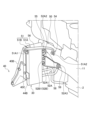
- Figs. 2 and 3 are front and rear perspective views of the cooling duct and the mounting mechanism for the cooling duct
- Fig. 4(A) is a right side view showing the cooling duct and the mounting mechanism
- Fig. 4(B) is an enlarged view of the main parts
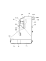
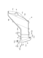
- Figs. 5 to 7 are left side, front, and bottom views showing the cooling duct and the mounting mechanism.
- the cooling duct 40 comprises a duct front portion (first portion) 40A having a duct opening 41 at the front end, a duct middle portion (second portion) 40B extending in the fore-and-aft direction and inclining upward toward the rear, and a duct rear portion (third portion) 40C having a connection opening 43 at the rear end.
- the cooling duct 40 also has a duct support portion 44 for mounting and fixing to the vehicle body frame 10.
- the cooling duct 40 When the vehicle is running, the cooling duct 40 first introduces airflow from the duct opening 41 connected to the sub-opening 25. Next, the duct front 40A, duct middle 40B, and duct rear 40C smoothly guide all of the airflow introduced from the duct opening 41 toward the connection opening 43 located rearward and above the duct opening 41. The airflow guided to the connection opening 43 is efficiently supplied to the entire cooling surface 30a on which the fins and other parts of the oil cooler 30 are arranged, allowing the oil cooler 30 to be efficiently air-cooled.
- the duct opening 41 is rectangular and elongated in the left-right direction to match the sub-opening 25, and is positioned on the left-right end side of the front bumper 22. Specifically, as shown in Figs. 2 and 7, the duct opening 41 has a first duct opening 41a on the inside in the left-right direction that extends in the left-right direction in a plan view or bottom view, a second duct opening 41b on the outside in the left-right direction that inclines backward toward the left-right outside, and a vertical cylindrical portion 45 that is positioned at the boundary between the first duct opening 41a and the second duct opening 41b.
- the cylindrical portion 45 is disposed below the fog lamp 24 when viewed from the front.
- a light axis adjustment unit (not shown) that supports the fog lamp 24 so that it can swing left and right is installed inside the cylindrical portion 45.
- the bottom side of the cylindrical portion 45 is open so that a tool for adjusting the light axis of the fog lamp 24 can be inserted.
- the top surface of the duct front 40A protrudes further forward than the bottom surface.
- the left and right inner sides of the cylindrical section 45 of the duct front 40A are shaped like a rectangle that is long in the left-right direction in a plan view, so that their front-to-back widths are approximately the same.
- the left and right outer sides of the cylindrical section 45 of the duct front 40A are shaped like a triangle in a plan view, so that their front-to-back widths gradually narrow as they go out to the left and right.
- the duct middle section 40B is formed so that the entire section slopes upward as it approaches the rear.
- the front end side of the duct middle section 40B is formed into a rectangular shape that is narrow in the vertical direction and wide in the horizontal direction in accordance with the shape of the sub-opening 25.
- the rear end side of the duct middle section 40B is formed into a rectangular shape that is wide in the vertical direction and narrow in the horizontal direction in accordance with the front shape of the vertical oil cooler 30.
- the left-right inner sides are gently inclined outwardly to the left and right as they move rearward, so that the left-right width of the duct middle section 40B gradually narrows.
- the left-right width of the duct middle section 40B is formed so that it fits within the left-right width of the oil cooler 30 at the midpoint in the fore-and-aft direction. In other words, in the rear part of the duct middle section 40B, it extends rearward with the left-right width remaining almost unchanged.
- the vertical width of the duct middle section 40B at the front of the duct middle section 40B, as shown in Figures 4(A) and 5, the vertical width does not change much and the section gently slopes upward toward the rear.
- the lower surface extends rearward in a generally horizontal state toward the lower part of the oil cooler 30, while the upper surface slopes steeply rearward and upward toward the upper part of the oil cooler 30.
- the vertical width is gradually increased toward the rear.
- the duct rear section 40C is formed into a rectangular column shape by extending approximately horizontally from the rear end of the duct middle section 40B toward the rear oil cooler 30.
- the rear end of the duct rear section 40C has a connection opening 43 whose left-right and top-bottom widths are approximately the same as or slightly smaller than the cooling surface 30a of the oil cooler 30 when viewed from the front.
- the duct rear section 43C is attached to the oil cooler 30 side with a slight gap between the connection opening 43 and the oil cooler 30.
- the second duct opening 41b is inclined backward toward the left and right outside, so that when the vehicle is traveling, the airflow can be efficiently guided to the duct opening 41 arranged on the left and right outside. Also, by arranging the cylindrical portion 45 between the first duct opening 41a and the second duct opening 41b, the strength of the duct opening 41 of the cooling duct 40 can be kept high. Furthermore, the airflows introduced from different angles at the first duct opening 41a and the second duct opening 41b can be straightened by the cylindrical portion 45 and smoothly taken into the cooling duct 40.
- the upper surface protrudes further forward than the lower surface, so that the air flow blowing from the bottom to the top can be efficiently guided to the duct opening 41 while the vehicle is moving.
- the amount of air supplied to the oil cooler 30 via the cooling duct 40 can be increased.
- the duct opening 41 formed on the left and right ends of the lower front part of the vehicle body becomes less noticeable.
- the duct front section 40A is disposed in the dead space below the bumper beam 13
- the duct middle section 40B is inclined upward as a whole while only the left and right inner sections are inclined narrowly to avoid interference with the side member 11
- the duct rear section 40C is connected to the oil cooler 30 supported on the outer surface of the side member 11.
- the left outer side surface of the cooling duct 40 extends straight backwards in a linear manner so as to be substantially parallel and flush from the duct opening 41 at the front end to the connection opening 43 at the rear end when viewed from the front, as shown in FIG. 6.
- cooling duct 40 compactly and space-efficiently on the front lateral side of the body frame 10 without protruding to the left or right outside of the body, while at the same time forming a large duct opening 41 that introduces the airflow supplied to the oil cooler 30.
- the duct support portion 44 has a front support portion 44A that supports the front portion of the cooling duct 40 on the vehicle body frame 10 side, and a rear support portion 44B that supports the rear end of the cooling duct 40 on the oil cooler 30 side.
- the front support portion 44A is a member that extends upward from the top surface of the duct middle portion 40B.
- the upper end side of the front support portion 44A is provided with fixing pins 46 made of resin or the like for fixing the pins to the left and right outer sides of the crash can 12.
- the rear support portion 44B is a pair of upper and lower plate-like members welded to the side surface of the oil cooler 30.
- the rear support portion 44B is formed to protrude at least forward, and is configured so that the forward protruding portion of the rear support portion 44B and the duct rear portion 40C can be pinned using a fixing pin 46 made of resin or the like.
- the rear portion of the cooling duct 40 is also indirectly supported by the vehicle body frame 10 side by being attached to the oil cooler 30, which is attached and fixed to the side member 11 side by the mounting mechanism 50.
- Figures 8(A) and 8(B) are a front perspective view and a rear perspective view of the main part showing the first mounting part
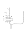
- Figure 9 is a cross-sectional view of the main part showing the mounting part on the side member side.
- the mounting mechanism 50 includes a first bracket 51 that connects the left and right outer side surfaces of the side member 11 to the left and right outer side surfaces of the oil cooler 30, and a second bracket 52 that connects the left and right outer side surfaces of the side member 11 to the left and right inner side surfaces of the oil cooler 30.
- the first bracket 51 is a plate-like member extending in the left-right direction, and has a first sub-bracket 51B, one end of which is attached and fixed to a first attachment portion 53 provided on the upper part of the left and right outer side of the oil cooler 30, and a first main bracket 51A, one end of which is attached and fixed to a third attachment portion 54 provided on the outer side of the side member 11.
- the first sub-bracket 51B has a sub-side connecting portion 51B1 that is attached to the first main bracket 51A side, and is fixed by welding or the like to the first mounting portion 53 on the left and right outer side surfaces of the oil cooler 30.
- the first main bracket 51A has a frame side mounting portion 51A2 that attaches the left and right inner ends to the third mounting portion 54 side, and a main side connecting portion 51A1 that attaches the left and right outer ends to the first sub-bracket 51B side.
- the first main bracket 51A extends in the left-right direction from the side member 11 side, via the upper rear side of the oil cooler 30, to the upper left and right outer side surfaces of the oil cooler 30. At this time, the first main bracket 51A is formed with a bent portion 55 that is convex upward in the middle in the left-right direction. In addition, on the left and right outer sides of the bent portion 55 of the first main bracket 51A, inclined portions 56 that are inclined forward so as to approach the oil cooler side in a plan view are formed (see Figures 7 and 8 (A)).
- the second bracket 52 has a second sub-bracket 52B that is attached and fixed to a second mounting portion 57 provided on the left and right inner side surfaces of the oil cooler 30, and a second main bracket 52A that is a plate-shaped member extending in the front-rear direction.
- the second main bracket 52A has a longitudinal midsection attached and fixed to the second sub-bracket 52B, a front end attached and fixed to a front fourth attachment portion 58 provided on the left and right outer side surfaces of the side member 11, and a rear end attached and fixed to a rear fourth attachment portion 59 provided on the left and right outer side surfaces of the side member 11.
- the second main bracket 52A is bent at the center in the front-rear direction so that it protrudes in the left-right direction from the side member 11 side toward the oil cooler 30 side, thereby forming a main side connecting portion 52A1 that is attached to the second sub-bracket 52B.
- the front and rear ends of the second main bracket 52A are formed with mounting portions 52A2, 52A3 that are fixedly attached to fourth mounting portions 58, 59 on the outer side surface of the side member 11.
- the second sub-bracket 52B is a plate-like member that is fixed by welding or the like to the second mounting portion 57 on the left and right inner side surfaces of the oil cooler, and extends to the rear side of the oil cooler 30 to form a sub-side connecting portion 52B1 that connects to the main-side connecting portion 52A1 of the second main bracket 52A.
- the first mounting portion 53 on the outer side surface of the oil cooler 30 and the second mounting portion 57 on the inner side surface of the oil cooler 30 are offset in the vertical direction.
- the first mounting portion 53 to which the first sub-bracket 51B is attached is located higher in a side view than the second mounting portion 57 to which the second sub-bracket 52B is attached.
- the third mounting portion 54, the front fourth mounting portion 58, and the rear fourth mounting portion 59 provided on the outer side surface of the side member 11 are offset in the up-down direction and the front-to-rear direction.
- the vertical positions of the mounting portions 54, 58, 59 are arranged in the order of the third mounting portion 54, the front fourth mounting portion 58, and the rear fourth mounting portion 59 from the top.
- the front-to-rear positions of the mounting portions 54, 58, 59 are arranged in the order of the front fourth mounting portion 58, the third mounting portion 54, and the rear fourth mounting portion 59 from the front.
- the brackets 51, 52 are removably attached to the third mounting portion 54, the front fourth mounting portion 58, and the rear fourth mounting portion 59 on the side member 11 side using fixing bolts 47 and nuts 48, but an elastic member 49 for vibration isolation is interposed between the fixing bolt 47 inserted into the side member 11 side and the side member 11.
- the main side connecting portion 51A1 and the sub side connecting portion 51B1 on the first bracket 51 side, and the main side connecting portion 52A1 and the sub side connecting portion 52B1 on the second bracket 52 side are connected in a detachable configuration using fixing bolts 47 and nuts 48.
- the main side connecting portion 51A1a of the first main bracket 51A is formed with a support piece 60 that supports the first sub-bracket 51B fixed to the side of the oil cooler 30.
- the support piece 60 is formed by bending forward an extension portion that extends further downward from the lower end side of the main side connecting portion 51A1 of the first main bracket 51A.
- the oil cooler 30 when attaching the oil cooler 30 to the first main bracket 51A side, the oil cooler 30 can be temporarily placed on the support piece 60 of the first main bracket 51A. This makes it easier to assemble the sub-side connecting portion 51B1 of the first sub-bracket 51B and the main-side connecting portion 51A1 of the first main bracket 51A with bolts.
- the first sub-bracket 51B protrudes forward from the side of the oil cooler 30, and also functions as a rear support part 44B for attaching the cooling duct 40 to the oil cooler 30.
- the present invention is not limited to the above-described embodiment, and can be modified or improved as appropriate.
- a heat exchanger disposed on an outer side in a vehicle width direction of a side member extending in a front-rear direction; a bracket for fixing the heat exchanger to the side member;
- a mounting structure for a heat exchanger comprising: the heat exchanger is attached to the bracket by a first attachment portion provided on one side surface of the heat exchanger in the vehicle width direction and a second attachment portion provided on the other side surface of the heat exchanger in the vehicle width direction;
- the first mounting portion and the second mounting portion are disposed at positions offset in the vertical direction.
- Heat exchanger mounting structure According to this configuration, the moment acting on the heat exchanger when the vehicle is traveling is reduced, and the heat exchanger can be fixed to the side member more firmly and stably.
- the first attachment portion is provided on an outer side of the heat exchanger in a vehicle width direction
- the second mounting portion is provided on an inner side of the heat exchanger in a vehicle width direction
- the first mounting portion is disposed above the second mounting portion.
- the bracket is a first bracket attached to the first attachment portion and a third attachment portion provided on a side surface of the side member on an outer side in a vehicle width direction; a second bracket attached to the second attachment portion and a fourth attachment portion provided on a side surface of the side member on an outer side in a vehicle width direction; having A mounting structure for a heat exchanger according to (1) or (2). According to this configuration, the moment acting on the heat exchanger fixedly attached to the side member can be reduced with a simple configuration.
- the third mounting portion is disposed above the fourth mounting portion.
- a mounting structure for a heat exchanger as described in (3) According to this configuration, the moment acting on the heat exchanger fixedly attached to the side member can be reduced with a simple configuration.
- the second bracket is attached to the side member by a front-side fourth attachment portion on a front side of the heat exchanger and a rear-side fourth attachment portion on a rear side of the heat exchanger.
- the front fourth mounting portion is disposed higher than the rear fourth mounting portion.
- a mounting structure for a heat exchanger as described in (5) According to this configuration, the moment acting on the heat exchanger fixedly attached to the side member can be reduced with a simple configuration.
- the front fourth mounting portion, the third mounting portion, and the rear fourth mounting portion are arranged in this order from the front side.
- the first bracket has an inclined portion extending from the third mounting portion toward an outer side in a vehicle width direction, the inclined portion being inclined toward the heat exchanger side in a plan view.
- the first bracket has a bent portion that extends from the third attachment portion toward an outer side in a vehicle width direction and that protrudes upward toward a center side in the vehicle width direction in a front view.
- a mounting structure for a heat exchanger according to any one of (3) to (8). According to this configuration, a space can be secured behind the oil cooler, and when the vehicle collides with a foreign object, the bent portion of the first bracket bends further to absorb the impact.
- the second bracket is provided to extend in a front-rear direction along the side member, and has a C-shape with a central portion in the front-rear direction protruding toward the heat exchanger.
- the heat exchanger includes a cooling duct for introducing cooling air into a front side thereof,
- the cooling duct is attached to the heat exchanger by the first bracket.
- the first mounting portion can serve as both a component for mounting the heat exchanger to the side member side and a component for mounting the cooling duct to the heat exchanger side, thereby making it possible to reduce the number of components.
- the first bracket includes a first sub-bracket attached to a heat exchanger side and a first main bracket attached to the third attachment portion, and the first sub-bracket is held and fixed to the first main bracket from below.
- the heat exchanger and the continuously variable transmission connected to the heat exchanger are disposed toward one end in the vehicle width direction.
- the heat exchanger is a vertical oil cooler,
- the bracket fixes the oil cooler to the side member with the cooling surface of the oil cooler facing forward.
Landscapes
- Engineering & Computer Science (AREA)
- Mechanical Engineering (AREA)
- Chemical & Material Sciences (AREA)
- Combustion & Propulsion (AREA)
- General Engineering & Computer Science (AREA)
- Transportation (AREA)
- Cooling, Air Intake And Gas Exhaust, And Fuel Tank Arrangements In Propulsion Units (AREA)
Priority Applications (2)
| Application Number | Priority Date | Filing Date | Title |
|---|---|---|---|
| PCT/JP2022/045981 WO2024127541A1 (ja) | 2022-12-14 | 2022-12-14 | 熱交換器の取付構造 |
| JP2024564031A JPWO2024127541A1 (https=) | 2022-12-14 | 2022-12-14 |
Applications Claiming Priority (1)
| Application Number | Priority Date | Filing Date | Title |
|---|---|---|---|
| PCT/JP2022/045981 WO2024127541A1 (ja) | 2022-12-14 | 2022-12-14 | 熱交換器の取付構造 |
Publications (1)
| Publication Number | Publication Date |
|---|---|
| WO2024127541A1 true WO2024127541A1 (ja) | 2024-06-20 |
Family
ID=91484549
Family Applications (1)
| Application Number | Title | Priority Date | Filing Date |
|---|---|---|---|
| PCT/JP2022/045981 Ceased WO2024127541A1 (ja) | 2022-12-14 | 2022-12-14 | 熱交換器の取付構造 |
Country Status (2)
| Country | Link |
|---|---|
| JP (1) | JPWO2024127541A1 (https=) |
| WO (1) | WO2024127541A1 (https=) |
Citations (3)
| Publication number | Priority date | Publication date | Assignee | Title |
|---|---|---|---|---|
| JP2003285654A (ja) * | 2002-03-28 | 2003-10-07 | Nissan Diesel Motor Co Ltd | 車両用熱交換器の取付構造 |
| JP2004340082A (ja) * | 2003-05-19 | 2004-12-02 | Mitsubishi Motors Corp | オイル冷却装置 |
| CN207984498U (zh) * | 2018-03-23 | 2018-10-19 | 安徽江淮汽车集团股份有限公司 | 一种冷凝器安装结构 |
-
2022
- 2022-12-14 WO PCT/JP2022/045981 patent/WO2024127541A1/ja not_active Ceased
- 2022-12-14 JP JP2024564031A patent/JPWO2024127541A1/ja active Pending
Patent Citations (3)
| Publication number | Priority date | Publication date | Assignee | Title |
|---|---|---|---|---|
| JP2003285654A (ja) * | 2002-03-28 | 2003-10-07 | Nissan Diesel Motor Co Ltd | 車両用熱交換器の取付構造 |
| JP2004340082A (ja) * | 2003-05-19 | 2004-12-02 | Mitsubishi Motors Corp | オイル冷却装置 |
| CN207984498U (zh) * | 2018-03-23 | 2018-10-19 | 安徽江淮汽车集团股份有限公司 | 一种冷凝器安装结构 |
Also Published As
| Publication number | Publication date |
|---|---|
| JPWO2024127541A1 (https=) | 2024-06-20 |
Similar Documents
| Publication | Publication Date | Title |
|---|---|---|
| US11173776B2 (en) | Vehicle body front structure for electric vehicle | |
| US5271473A (en) | Front body structure for automotive vehicle | |
| US8403404B2 (en) | Vehicle body front structure and manufacturing method thereof | |
| US6540037B2 (en) | Vehicle front end panel | |
| CN110816674A (zh) | 车辆前部结构 | |
| KR100936979B1 (ko) | 자동차의 프런트 엔드 모듈 | |
| CN105313983B (zh) | 车辆的前部车身结构 | |
| CN101808880A (zh) | 具有插置在减震器和主纵梁间的刚性梁的机动车前面罩 | |
| US6789606B2 (en) | Front construction of motor vehicle body and heat exchanger support frame used therefor | |
| JP5084805B2 (ja) | 車両用フロントグリルブラケット | |
| EP1690722A2 (en) | Mount apparatus mounting structure | |
| WO2024127541A1 (ja) | 熱交換器の取付構造 | |
| KR101518514B1 (ko) | 쿨링모듈의 파손을 방지할 수 있는 프론트 엔드 모듈 | |
| JP3125573B2 (ja) | 車両のラジエータコアサポート構造 | |
| WO2024127540A1 (ja) | 車両前部構造 | |
| JP3728955B2 (ja) | 燃料噴射制御ユニットの取付部構造 | |
| KR100946483B1 (ko) | 프런트 엔드 모듈의 범퍼백빔 장착구조 | |
| KR102050989B1 (ko) | 차량용 쿨링모듈 | |
| JP2023117383A (ja) | 自動車用車体構造 | |
| JP5073787B2 (ja) | 車体前部構造 | |
| JP2004237787A (ja) | 自動車の前部構造 | |
| JP2016130074A (ja) | 車両用導風構造 | |
| KR102050986B1 (ko) | 차량용 캐리어 | |
| JP3308112B2 (ja) | 自動車の車体前部構造 | |
| JP7380397B2 (ja) | 車両前部構造 |
Legal Events
| Date | Code | Title | Description |
|---|---|---|---|
| 121 | Ep: the epo has been informed by wipo that ep was designated in this application |
Ref document number: 22968453 Country of ref document: EP Kind code of ref document: A1 |
|
| DPE1 | Request for preliminary examination filed after expiration of 19th month from priority date (pct application filed from 20040101) | ||
| WWE | Wipo information: entry into national phase |
Ref document number: 2024564031 Country of ref document: JP |
|
| NENP | Non-entry into the national phase |
Ref country code: DE |
|
| 122 | Ep: pct application non-entry in european phase |
Ref document number: 22968453 Country of ref document: EP Kind code of ref document: A1 |