WO2024122161A1 - ラジアントバーナ - Google Patents
ラジアントバーナ Download PDFInfo
- Publication number
- WO2024122161A1 WO2024122161A1 PCT/JP2023/034372 JP2023034372W WO2024122161A1 WO 2024122161 A1 WO2024122161 A1 WO 2024122161A1 JP 2023034372 W JP2023034372 W JP 2023034372W WO 2024122161 A1 WO2024122161 A1 WO 2024122161A1
- Authority
- WO
- WIPO (PCT)
- Prior art keywords
- injection hole
- mixed gas
- combustion space
- burner
- nozzle
- Prior art date
- Legal status (The legal status is an assumption and is not a legal conclusion. Google has not performed a legal analysis and makes no representation as to the accuracy of the status listed.)
- Ceased
Links
Images



Classifications
-
- F—MECHANICAL ENGINEERING; LIGHTING; HEATING; WEAPONS; BLASTING
- F23—COMBUSTION APPARATUS; COMBUSTION PROCESSES
- F23D—BURNERS
- F23D14/00—Burners for combustion of a gas, e.g. of a gas stored under pressure as a liquid
- F23D14/12—Radiant burners
-
- F—MECHANICAL ENGINEERING; LIGHTING; HEATING; WEAPONS; BLASTING
- F23—COMBUSTION APPARATUS; COMBUSTION PROCESSES
- F23D—BURNERS
- F23D14/00—Burners for combustion of a gas, e.g. of a gas stored under pressure as a liquid
- F23D14/02—Premix gas burners, i.e. in which gaseous fuel is mixed with combustion air upstream of the combustion zone
-
- F—MECHANICAL ENGINEERING; LIGHTING; HEATING; WEAPONS; BLASTING
- F23—COMBUSTION APPARATUS; COMBUSTION PROCESSES
- F23D—BURNERS
- F23D14/00—Burners for combustion of a gas, e.g. of a gas stored under pressure as a liquid
- F23D14/46—Details
- F23D14/48—Nozzles
- F23D14/58—Nozzles characterised by the shape or arrangement of the outlet or outlets from the nozzle, e.g. of annular configuration
-
- F—MECHANICAL ENGINEERING; LIGHTING; HEATING; WEAPONS; BLASTING
- F23—COMBUSTION APPARATUS; COMBUSTION PROCESSES
- F23M—CASINGS, LININGS, WALLS OR DOORS SPECIALLY ADAPTED FOR COMBUSTION CHAMBERS, e.g. FIREBRIDGES; DEVICES FOR DEFLECTING AIR, FLAMES OR COMBUSTION PRODUCTS IN COMBUSTION CHAMBERS; SAFETY ARRANGEMENTS SPECIALLY ADAPTED FOR COMBUSTION APPARATUS; DETAILS OF COMBUSTION CHAMBERS, NOT OTHERWISE PROVIDED FOR
- F23M5/00—Casings; Linings; Walls
- F23M5/02—Casings; Linings; Walls characterised by the shape of the bricks or blocks used
-
- F—MECHANICAL ENGINEERING; LIGHTING; HEATING; WEAPONS; BLASTING
- F23—COMBUSTION APPARATUS; COMBUSTION PROCESSES
- F23D—BURNERS
- F23D2900/00—Special features of, or arrangements for burners using fluid fuels or solid fuels suspended in a carrier gas
- F23D2900/14—Special features of gas burners
- F23D2900/14021—Premixing burners with swirling or vortices creating means for fuel or air
Definitions
- a radiant burner heats the surface of a burner tile by burning fuel, and heats an object by radiating heat from the heated surface.
- Patent Document 1 discloses such a radiant burner.
- an outlet for a mixture of fuel and air is located at a position separated from the bottom of the cup.
- An impact plate is provided to face the outlet. The impact plate changes the direction of the mixture from the outlet. The impact plate guides the mixture radially outward toward the surface of the cup.
- the mixture collides with the surface of the cup and decelerates. Therefore, it takes a longer time for the mixture to collide with the surface of the cup again. During this time, the mixture is sufficiently heated and burned.
- problems such as insufficient combustion of fuel are solved when a fuel with a slow burning speed, such as natural gas or liquefied petroleum gas, is used.
- Ammonia is known as a fuel that does not emit CO2 .
- the burning speed of ammonia is much slower than that of natural gas. Therefore, when using ammonia in a radiant burner, unburned ammonia due to insufficient combustion can be a problem.
- the present disclosure aims to provide a radiant burner that can reduce unburned ammonia when ammonia is used as fuel.
- a radiant burner comprises a burner tile and a nozzle protruding from the burner tile toward a combustion space in a first direction, the nozzle including a first injection hole for injecting gas containing ammonia into the combustion space, the first injection hole being disposed at a position spaced apart from the surface of the burner tile and opening toward the first direction, the nozzle including a swirler for imparting a swirling flow centered on the first direction to the gas injected from the first injection hole.
- the burner tile may include a recess that opens toward the first direction as the combustion space, the nozzle may protrude into the recess, and the first injection hole may be positioned at a position spaced apart from the bottom of the recess.
- the depression may have a hemispherical shape.
- the nozzle may include a second injection hole that injects gas containing ammonia into the combustion space, the second injection hole being positioned at a distance from the surface of the burner tile and opening toward a second direction intersecting the first direction.
- the nozzle may include a flow passage in fluid communication with the first injection hole, and a rod disposed within the flow passage and supporting the swirler, the rod protruding from the first injection hole into the combustion space or facing the combustion space through the first injection hole.
- ammonia when used as fuel in a radiant burner, unburned ammonia can be reduced.
- FIG. 1 is a schematic cross-sectional view showing a radiant burner according to a first embodiment.
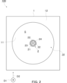
- FIG. 2 is a schematic front view showing the radiant burner of FIG.
- FIG. 3 is a cross-sectional view showing a schematic flow of a mixed gas flowing in the radiant burner of FIG.
- FIG. 4 is a schematic cross-sectional view showing a radiant burner according to the second embodiment.
- FIG. 5 is a cross-sectional view showing a schematic flow of the mixed gas flowing in the radiant burner of FIG.
- FIG. 6 is a schematic cross-sectional view showing a radiant burner according to the third embodiment.
- FIG. 1 is a schematic cross-sectional view showing a radiant burner 100 according to the first embodiment.
- FIG. 2 is a schematic front view showing the radiant burner 100 of FIG. 1.
- the radiant burner 100 heats the surface 11 of the burner tile 1 by burning a mixed gas of ammonia and air, and heats an object (not shown) located at a position away from the radiant burner 100 by radiant heat from the heated surface 11.
- the radiant burner 100 includes a burner tile 1 and a nozzle 2.
- the radiant burner 100 may further include other components.
- the burner tile 1 is formed of a refractory material, such as a molded product containing ceramic. In this embodiment, the burner tile 1 has a roughly rectangular parallelepiped shape. The burner tile 1 is not limited to this and may have other shapes.
- the burner tile 1 includes a front surface 12 that is arranged to face the target object, and a back surface 13 opposite the front surface 12.
- the burner tile 1 includes a recess 14 on the front surface 12.
- the recess 14 is formed from the front surface 12 toward the back surface 13.
- the recess 14 is defined by the surface 11.
- the recess 14 is used as a combustion space S.
- combustion space means a space in which a mixture of fuel and air is burned.
- the recess 14 has a hemispherical shape.
- the recess 14 may have other shapes, such as a cylindrical shape or a polygonal prism shape.
- the recess 14 opens toward a first direction D1.
- the first direction D1 may also be referred to as a "central axis direction.”
- the burner tile 1 may not include a recess 14.
- burner tile 1 may also be referred to as a "radiant cup.”
- radiant burner 100 may also be referred to as a "radiant cup burner.”
- the nozzle 2 protrudes from the burner tile 1 toward the combustion space S along the first direction D1.
- the nozzle 2 injects fuel containing ammonia into the combustion space S.
- the nozzle 2 injects a mixed gas of ammonia and air into the combustion space S (premixing type).
- the radiant burner 100 is not limited to the premixing type, and may be a diffusion type.
- the nozzle 2 includes a case 21, a swirler 22, and a rod 23.
- the case 21 has a generally cylindrical or tubular shape.
- the case 21 is attached to the burner tile 1 so that its central axis is parallel to the first direction D1.
- the case 21 is located at the center of the hemispherical recess 14.
- the case 21 penetrates the wall of the burner tile 1 from the back surface 13 and protrudes into the recess 14.
- the "central axial direction”, “radial direction”, and “circumferential direction” of the case 21 may be simply referred to as the "central axial direction”, "radial direction”, and “circumferential direction”.
- the case 21 includes a first injection hole 24.
- the first injection hole 24 injects the mixed gas into the combustion space S.
- the first injection hole 24 is located at the tip of the case 21. That is, the first injection hole 24 is arranged at a position separated from the surface 11. Specifically, in this embodiment, the first injection hole 24 is located within the combustion space S and at a position separated from the bottom of the recess 14.
- the first injection hole 24 opens toward the first direction D1.
- the first injection hole 24 has a circular shape.
- the inner wall of the case 21 defines a flow path 25 for the mixed gas.
- the flow path 25 is in fluid communication with the first injection hole 24.
- the flow path 25 has a generally cylindrical shape.
- the case 21 includes a throttling portion 26.
- the throttling portion 26 narrows the cross-sectional area of the flow passage 25 in a portion of the flow passage 25.
- the throttling portion 26 protrudes radially inward from an inner wall that defines the flow passage 25.
- the throttling portion 26 has a circular ring shape.
- the throttling portion 26 is disposed between the first injection hole 24 and the swirler 22.
- the case 21 does not need to include the throttling portion 26.
- the swirler 22 imparts a swirling flow centered on the first direction D1 to the mixed gas injected from the first injection hole 24.
- the swirler 22 is disposed in the flow path 25.
- the swirler 22 is supported by the rod 23.
- the swirler 22 includes a plurality of blades protruding radially outward from the rod 23.
- the swirler 22 and the rod 23 are fixed relative to the case 21.
- the swirler 22 changes the direction of the flow of the mixed gas while the mixed gas passes between the blades, imparting a swirling flow to the mixed gas.
- the rod 23 is disposed in the flow path 25 on the central axis of the case 21.
- the rod 23 extends along the central axis of the case 21.
- the rod 23 protrudes beyond the first injection hole 24 into the combustion space S. That is, in this embodiment, the tip 23a of the rod 23 is located within the combustion space S. In other embodiments, the rod 23 does not have to protrude from the first injection hole 24 into the combustion space S.
- FIG. 3 is a cross-sectional view showing the schematic flow of mixed gases F, F1, and F2 flowing within the radiant burner 100 of FIG. 1.
- the mixed gas F flows through a flow path 25.
- the swirler 22 imparts a swirling flow to the mixed gas F.
- the swirling flow of the mixed gas F is narrowed by the narrowing section 26. This increases the flow velocity of the mixed gas F and reduces unevenness in the flow of the mixed gas F.
- the first injection hole 24 injects the swirling mixed gas F into the combustion space S.
- the mixed gas F flows radially outward due to the centrifugal force generated by the swirling.
- a part of the mixed gas F1 injected from the first injection hole 24 flows along the surface 11.
- the pressure in the central region of the combustion space S more specifically the pressure around the tip 23a, is lower than the pressure in the surrounding region. Therefore, the mixed gas F1 changes its flow direction from the radially outer side to the radially inner side, and further flows along the central axis toward the tip 23a.
- the mixed gas F1 ignites starting from the tip 23a, and is sufficiently heated and combusted before changing its flow direction.
- the high-temperature combustion gas flows toward the tip 23a.
- the high-temperature combustion gas near the tip 23a contributes to heating the injected mixed gas F1.
- the pressure in the area between the first injection hole 24 and the surface 11 around the nozzle 2 is also lower than the pressure in the surrounding area. Therefore, the remaining mixed gas F2 injected from the first injection hole 24 flows toward this space.
- This mixed gas F2 forms a circulating flow along the surface 11 around the nozzle 2. Since the surface 11 is heated by the flame, the mixed gas F2 is sufficiently heated by the surface 11 while circulating. A portion of the heated mixed gas F2 merges with the mixed gas F1. Therefore, the mixed gas F can be sufficiently heated.
- the mixed gas F can be burned at the intended position in the combustion space S. Furthermore, since the mixed gas F can be burned at the intended position in the combustion space S, the surface 11 can be sufficiently heated as intended. Furthermore, since the mixed gas F is sufficiently heated, the mixed gas F is sufficiently burned. Therefore, the amount of unburned ammonia in the exhaust gas can be reduced.
- the radiant burner 100 as described above comprises a burner tile 1 and a nozzle 2 protruding from the burner tile 1 toward the combustion space S along a first direction D1.
- the nozzle 2 includes a first injection hole 24 for injecting a mixed gas containing ammonia into the combustion space S.
- the first injection hole 24 is disposed at a position spaced apart from the surface 11 of the burner tile 1 and opens toward the first direction D1.
- the nozzle 2 also includes a swirler 22 for imparting a swirling flow centered on the first direction D1 to the mixed gas F injected from the first injection hole 24.
- the mixed gas F2 is sufficiently heated by the surface 11 while circulating. Therefore, the mixed gas F can be sufficiently heated. This helps prevent problems such as insufficient heating of the surface 11 and an increase in unburned ammonia in the exhaust gas.
- the burner tile 1 also includes a recess 14 that opens in the first direction D1 as the combustion space S, the nozzle 2 protrudes into the recess 14, and the first injection hole 24 is positioned at a distance from the bottom of the recess 14.
- the flow of the mixed gases F1 and F2 is surrounded by the recess 14. Therefore, a circulating flow can be easily formed.
- the mixed gas cannot be burned at the intended position due to insufficient heating, there is a risk that the flame will jump out of the recess 14. This is called lifting.
- the mixed gas F can be burned at the intended position in the combustion space S, so that flame lifting can be suppressed.
- the recess 14 has a hemispherical shape. With this configuration, the mixed gases F1 and F2 can flow smoothly along the hemispherical shape. Therefore, a circulation flow can be formed more easily.
- the nozzle 2 also includes a rod 23 that is disposed within the flow path 25 and supports the swirler 22, and the rod 23 protrudes from the first injection hole 24 into the combustion space S.
- the tip 23a of the rod 23 acts as the starting point for ignition as the combustion gas returning from the surface 11 to the central region and the injected mixed gas F1 join together. Therefore, the mixed gas F1 can be combusted well.
- FIG. 4 is a schematic cross-sectional view showing a radiant burner 200 according to the second embodiment.
- the radiant burner 200 differs from the radiant burner 100 according to the first embodiment in that the nozzle 2 further includes a plurality of second injection holes 27.
- the configuration of the radiant burner 200 may be the same as that of the radiant burner 100.
- the case 21 includes a plurality of second injection holes 27.
- the number of the second injection holes 27 may be two, three, four, five, or more.
- the plurality of second injection holes 27 are evenly arranged along the circumferential direction.
- the second injection holes 27 inject the mixed gas into the combustion space S.
- the second injection hole 27 is located between the first injection hole 24 and the swirler 22 in the first direction D1.
- the second injection hole 27 is formed in the throttling section 26.
- the second injection hole 27 may be formed at a position upstream or downstream of the throttling section 26.
- the second injection hole 27 is located within the combustion space S and is disposed at a position spaced apart from the bottom of the recess 14.
- the second injection hole 27 opens toward a second direction D2 that intersects with the first direction D1.
- the second direction D2 is perpendicular to the first direction D1. That is, in this embodiment, the second direction D2 corresponds to the radial direction. In other embodiments, the second direction D2 does not have to be perpendicular to the first direction D1, and may be inclined with respect to the radial direction.
- the second injection hole 27 may have various shapes, such as a circular shape, an elliptical shape, or a polygonal shape.
- FIG. 5 is a cross-sectional view showing the schematic flow of mixed gases F, F3, F4, and F5 flowing within the radiant burner 200 of FIG. 4.
- the mixed gas F flows through a flow path 25.
- the swirler 22 imparts a swirling flow to the mixed gas F.
- the swirling flow of the mixed gas F is narrowed by the narrowing portion 26. This increases the flow velocity of the mixed gas F and reduces unevenness in the flow of the mixed gas F.
- the first injection hole 24 injects a portion of the swirling mixed gas F3 into the combustion space S.
- the mixed gas F3 flows radially outward due to the centrifugal force generated by the swirling.
- the pressure in the central region of the combustion space S more specifically the pressure around the tip 23a, is lower than the pressure in the surrounding region. Therefore, the mixed gas F3 changes its flow direction from the radially outer side to the radially inner side, and further flows along the central axis toward the tip 23a.
- the mixed gas F3 ignites starting from the tip 23a, and is sufficiently heated and combusted before changing its flow direction.
- the high-temperature combustion gas flows toward the tip 23a.
- the second injection hole 27 also injects the remaining swirling mixed gas F into the combustion space S.
- a part of this mixed gas, F4 forms a flow along the surface 11. Since the surface 11 is heated by the flame, the mixed gas F4 is heated by the surface 11.
- the mixed gas F4 changes its flow direction from the radially outer side to the radially inner side, forming a circulating flow toward the second injection hole 27.
- the mixed gas F4 is ignited starting from the vicinity of the second injection hole 27, and is sufficiently heated and combusted before changing its flow direction.
- a part of the high-temperature combustion gas flows toward the vicinity of the first injection hole 24, and the rest flows toward the vicinity of the second injection hole 27.
- the high-temperature combustion gas contributes to heating the mixed gas F3 injected near the first injection hole 24, and also contributes to heating the mixed gas F4 injected near the second injection hole 27.
- the pressure in the area between the second injection hole 27 and the surface 11 around the nozzle 2 is also lower than the pressure in the surrounding area. Therefore, the remaining mixed gas F5 injected from the second injection hole 27 flows toward this space.
- This mixed gas F5 forms a circulating flow along the surface 11 around the nozzle 2. Since the surface 11 is heated by the flame, most of the mixed gas F5 is sufficiently heated by the surface 11 while circulating. A portion of the heated mixed gas F5 merges with the mixed gas F4. Therefore, the mixed gas F can be sufficiently heated.
- Such a radiant burner 200 has substantially the same effect as the radiant burner 100 according to the first embodiment.
- the nozzle 2 includes a second injection hole 27 that injects the mixed gas F into the combustion space S.
- the second injection hole 27 is disposed at a position spaced apart from the bottom of the recess 14, and opens toward a second direction D2 perpendicular to the first direction D1.
- the mixed gas is injected from both the first injection hole 24 and the second injection hole 27, so that the flow rate of the mixed gas decreases and the mixed gas remains in the recess 14 for a long time. Therefore, the mixed gas is sufficiently heated and becomes easier to burn.
- FIG. 6 is a schematic cross-sectional view showing a radiant burner 300 according to the third embodiment.
- the radiant burner 300 differs from the radiant burner 200 according to the second embodiment in that the nozzle 2 does not include the above-mentioned throttling portion 26 but includes an inner tube 28, and in that the rod 23 does not protrude into the combustion space S from the first injection hole 24.
- the inner cylinder 28 has a generally cylindrical shape.
- the inner cylinder 28 is disposed inside the case 21 and concentrically with the case 21.
- a gap is formed between the inner surface of the case 21 and the outer surface of the inner cylinder 28.
- the inner cylinder 28 is disposed upstream of the first injection hole 24.
- the downstream end of the inner cylinder 28 includes an inner cylinder end 28a that expands in the radial direction.
- the inner cylinder end 28a is connected to the inner surface of the case 21.
- the inner cylinder 28 may be formed integrally with the case 21, or may be formed separately from the case 21 and then attached to the case 21.
- the second injection hole 27 is formed between the upstream end and downstream end of the inner cylinder 28 in the central axial direction.
- the inner cylinder 28 divides a part of the flow path 25 into an inner portion connected to the first injection hole 24 and an outer portion connected to the second injection hole 27.
- the tip 23a of the rod 23 is positioned upstream of the first injection hole 24. Therefore, the tip 23a faces the combustion space S through the first injection hole 24. Specifically, in this embodiment, the tip 23a is positioned inside the inner cylinder 28.
- the swirler 22 is disposed inside the inner cylinder 28. Therefore, in this embodiment, the swirler 22 imparts a swirling flow to the mixed gas injected from the first injection hole 24.
- the configuration of the radiant burner 300 may be the same as that of the radiant burner 200 according to the second embodiment.
- Such a radiant burner 300 has roughly the same effect as the radiant burner 200 according to the second embodiment. Furthermore, in the radiant burner 300, the rod 23 faces the combustion space S through the first injection hole 24. Even in this configuration, the tip 23a of the rod 23 can contribute to the heating of the mixed gas F1 by the combustion gas returning from the surface 11 to the central region, and acts as the starting point of ignition. Therefore, the mixed gas F1 can be combusted well.
- both the first injection hole 24 and the second injection hole 27 are fluidly connected to the flow path 25.
- the case 21 may further include another flow path that is fluidly connected only to the second injection hole 27.
- the burner tile 1 includes a recess 14.
- the burner tile 1 may not include the recess 14 and may have a flat-wall shape or a flat plate shape.
- the nozzle 2 protrudes from a flat front surface 12 of the burner tile 1 that is arranged to face the target object. In this case, too, a flow of mixed gases F1 to F5 as shown in Figures 3 and 5 can occur.
- the present disclosure can facilitate the use of ammonia leading to reduced CO2 emissions, thereby contributing, for example, to Sustainable Development Goal (SDG) Goal 7 "Ensure access to affordable, reliable, sustainable and modern energy” and Goal 13 "Take urgent action to combat climate change and its impacts.”
- SDG Sustainable Development Goal
Landscapes
- Engineering & Computer Science (AREA)
- Chemical & Material Sciences (AREA)
- Combustion & Propulsion (AREA)
- Mechanical Engineering (AREA)
- General Engineering & Computer Science (AREA)
- Gas Burners (AREA)
Priority Applications (3)
| Application Number | Priority Date | Filing Date | Title |
|---|---|---|---|
| CN202380055565.7A CN119522344A (zh) | 2022-12-09 | 2023-09-21 | 辐射燃烧器 |
| JP2024562597A JP7819787B2 (ja) | 2022-12-09 | 2023-09-21 | ラジアントバーナ |
| KR1020257006707A KR20250040738A (ko) | 2022-12-09 | 2023-09-21 | 방사 버너 |
Applications Claiming Priority (2)
| Application Number | Priority Date | Filing Date | Title |
|---|---|---|---|
| JP2022196869 | 2022-12-09 | ||
| JP2022-196869 | 2022-12-09 |
Publications (1)
| Publication Number | Publication Date |
|---|---|
| WO2024122161A1 true WO2024122161A1 (ja) | 2024-06-13 |
Family
ID=91378734
Family Applications (1)
| Application Number | Title | Priority Date | Filing Date |
|---|---|---|---|
| PCT/JP2023/034372 Ceased WO2024122161A1 (ja) | 2022-12-09 | 2023-09-21 | ラジアントバーナ |
Country Status (4)
| Country | Link |
|---|---|
| JP (1) | JP7819787B2 (https=) |
| KR (1) | KR20250040738A (https=) |
| CN (1) | CN119522344A (https=) |
| WO (1) | WO2024122161A1 (https=) |
Citations (4)
| Publication number | Priority date | Publication date | Assignee | Title |
|---|---|---|---|---|
| JPS5028343U (https=) * | 1973-07-05 | 1975-04-01 | ||
| JPS5228755U (https=) * | 1975-08-21 | 1977-02-28 | ||
| JPS54130628U (https=) * | 1978-03-03 | 1979-09-11 | ||
| JP2016130619A (ja) * | 2015-01-15 | 2016-07-21 | 国立大学法人東北大学 | 低燃焼性燃料燃焼装置 |
Family Cites Families (1)
| Publication number | Priority date | Publication date | Assignee | Title |
|---|---|---|---|---|
| JPH11257614A (ja) * | 1998-03-12 | 1999-09-21 | Chugai Ro Co Ltd | 低カロリーガス燃焼用バーナ |
-
2023
- 2023-09-21 JP JP2024562597A patent/JP7819787B2/ja active Active
- 2023-09-21 CN CN202380055565.7A patent/CN119522344A/zh active Pending
- 2023-09-21 WO PCT/JP2023/034372 patent/WO2024122161A1/ja not_active Ceased
- 2023-09-21 KR KR1020257006707A patent/KR20250040738A/ko active Pending
Patent Citations (4)
| Publication number | Priority date | Publication date | Assignee | Title |
|---|---|---|---|---|
| JPS5028343U (https=) * | 1973-07-05 | 1975-04-01 | ||
| JPS5228755U (https=) * | 1975-08-21 | 1977-02-28 | ||
| JPS54130628U (https=) * | 1978-03-03 | 1979-09-11 | ||
| JP2016130619A (ja) * | 2015-01-15 | 2016-07-21 | 国立大学法人東北大学 | 低燃焼性燃料燃焼装置 |
Also Published As
| Publication number | Publication date |
|---|---|
| JP7819787B2 (ja) | 2026-02-25 |
| JPWO2024122161A1 (https=) | 2024-06-13 |
| KR20250040738A (ko) | 2025-03-24 |
| CN119522344A (zh) | 2025-02-25 |
Similar Documents
| Publication | Publication Date | Title |
|---|---|---|
| JP5663216B2 (ja) | 予混合パイロット用途におけるリーン直接噴射 | |
| JP6637905B2 (ja) | バーナ、燃焼器、及びガスタービン | |
| JP5364275B2 (ja) | 燃焼システムにおけるNOxエミッションを低減するのを可能にするための方法及びシステム | |
| CN100554785C (zh) | 用于对燃气轮机中的空气和气体进行混合的燃烧管及方法 | |
| RU2455569C1 (ru) | Горелка | |
| JP4670035B2 (ja) | ガスタービン燃焼器 | |
| CN100590359C (zh) | 燃烧器 | |
| US20070272201A1 (en) | Combustion Apparatus and Combustion Method | |
| US20090056336A1 (en) | Gas turbine premixer with radially staged flow passages and method for mixing air and gas in a gas turbine | |
| JP2009133599A (ja) | 燃焼システム内における逆火/保炎を減少させるのを可能にする方法及びシステム | |
| CN101294715A (zh) | 燃烧装置及烧嘴的燃烧方法 | |
| JPH02309124A (ja) | 燃焼器及びその運転方法 | |
| US20080193886A1 (en) | Combustion Apparatus | |
| CN101881448A (zh) | 径向贫直接注射燃烧器 | |
| CN105627363A (zh) | 燃烧器衬套 | |
| JP2004162959A (ja) | アニュラ型渦巻き拡散火炎燃焼器 | |
| JP7819787B2 (ja) | ラジアントバーナ | |
| JP3873119B2 (ja) | 円筒内旋回燃焼器 | |
| JPS597885B2 (ja) | ガスバ−ナノズル | |
| JP3826200B2 (ja) | 予混合燃焼器 | |
| JP2005226850A (ja) | 燃焼装置 | |
| JP3901663B2 (ja) | 急速混合燃料噴射弁及び低NOx燃焼器 | |
| CN105674333A (zh) | 地面燃机燃烧室结构及其分级燃烧组织方法 | |
| CA2599113C (en) | Fuel injection valve, combustor using the fuel injection valve, and fuel injection method for the fuel injection valve | |
| JP3951155B2 (ja) | 低NOx蒸気噴射燃焼器 |
Legal Events
| Date | Code | Title | Description |
|---|---|---|---|
| 121 | Ep: the epo has been informed by wipo that ep was designated in this application |
Ref document number: 23900286 Country of ref document: EP Kind code of ref document: A1 |
|
| WWE | Wipo information: entry into national phase |
Ref document number: 2024562597 Country of ref document: JP |
|
| WWE | Wipo information: entry into national phase |
Ref document number: 202380055565.7 Country of ref document: CN |
|
| WWP | Wipo information: published in national office |
Ref document number: 202380055565.7 Country of ref document: CN |
|
| ENP | Entry into the national phase |
Ref document number: 20257006707 Country of ref document: KR Kind code of ref document: A |
|
| WWE | Wipo information: entry into national phase |
Ref document number: 1020257006707 Country of ref document: KR |
|
| WWP | Wipo information: published in national office |
Ref document number: 1020257006707 Country of ref document: KR |
|
| NENP | Non-entry into the national phase |
Ref country code: DE |
|
| 122 | Ep: pct application non-entry in european phase |
Ref document number: 23900286 Country of ref document: EP Kind code of ref document: A1 |