WO2024121966A1 - 流体ノズル - Google Patents
流体ノズル Download PDFInfo
- Publication number
- WO2024121966A1 WO2024121966A1 PCT/JP2022/045075 JP2022045075W WO2024121966A1 WO 2024121966 A1 WO2024121966 A1 WO 2024121966A1 JP 2022045075 W JP2022045075 W JP 2022045075W WO 2024121966 A1 WO2024121966 A1 WO 2024121966A1
- Authority
- WO
- WIPO (PCT)
- Prior art keywords
- fluid
- discharge
- plate
- notches
- fluid nozzle
- Prior art date
Links
- 239000012530 fluid Substances 0.000 title claims abstract description 123
- 239000000463 material Substances 0.000 claims abstract description 37
- 238000011144 upstream manufacturing Methods 0.000 claims description 4
- 238000007599 discharging Methods 0.000 claims description 2
- 230000000149 penetrating effect Effects 0.000 claims description 2
- 238000010030 laminating Methods 0.000 abstract 1
- 239000002826 coolant Substances 0.000 description 63
- 230000001681 protective effect Effects 0.000 description 8
- 230000000052 comparative effect Effects 0.000 description 5
- 238000003860 storage Methods 0.000 description 5
- 230000000694 effects Effects 0.000 description 4
- 229910052751 metal Inorganic materials 0.000 description 4
- 239000002184 metal Substances 0.000 description 4
- 239000000853 adhesive Substances 0.000 description 2
- 230000001070 adhesive effect Effects 0.000 description 2
- 238000004140 cleaning Methods 0.000 description 2
- 238000010586 diagram Methods 0.000 description 2
- 238000003754 machining Methods 0.000 description 2
- 238000012986 modification Methods 0.000 description 2
- 230000004048 modification Effects 0.000 description 2
- 229910052782 aluminium Inorganic materials 0.000 description 1
- XAGFODPZIPBFFR-UHFFFAOYSA-N aluminium Chemical compound [Al] XAGFODPZIPBFFR-UHFFFAOYSA-N 0.000 description 1
- 230000000903 blocking effect Effects 0.000 description 1
- 238000001816 cooling Methods 0.000 description 1
- 238000005520 cutting process Methods 0.000 description 1
- 239000000428 dust Substances 0.000 description 1
- 238000009434 installation Methods 0.000 description 1
- 239000007788 liquid Substances 0.000 description 1
- 238000004519 manufacturing process Methods 0.000 description 1
- 239000007769 metal material Substances 0.000 description 1
- 230000002093 peripheral effect Effects 0.000 description 1
- 239000007787 solid Substances 0.000 description 1
- XLYOFNOQVPJJNP-UHFFFAOYSA-N water Substances O XLYOFNOQVPJJNP-UHFFFAOYSA-N 0.000 description 1
Images


Classifications
-
- B—PERFORMING OPERATIONS; TRANSPORTING
- B23—MACHINE TOOLS; METAL-WORKING NOT OTHERWISE PROVIDED FOR
- B23Q—DETAILS, COMPONENTS, OR ACCESSORIES FOR MACHINE TOOLS, e.g. ARRANGEMENTS FOR COPYING OR CONTROLLING; MACHINE TOOLS IN GENERAL CHARACTERISED BY THE CONSTRUCTION OF PARTICULAR DETAILS OR COMPONENTS; COMBINATIONS OR ASSOCIATIONS OF METAL-WORKING MACHINES, NOT DIRECTED TO A PARTICULAR RESULT
- B23Q11/00—Accessories fitted to machine tools for keeping tools or parts of the machine in good working condition or for cooling work; Safety devices specially combined with or arranged in, or specially adapted for use in connection with, machine tools
Definitions
- the present invention relates to a fluid nozzle that ejects a fluid.
- Fluid nozzles that are mounted on machine tools and eject fluids to a specified location for purposes such as removing chips generated during machining and cooling frictional heat have been known.
- the fluid nozzle shown in Patent Document 1 has a horizontally extending slit-shaped discharge hole formed in the coolant storage box, and coolant (an example of a fluid) is discharged from the discharge hole in a curtain-like shape to supply the coolant over a wide area.
- Patent Document 1 has the problem that a large coolant storage box is required, limiting the installation location.
- the present invention was made in consideration of the above situation, and its purpose is to provide a fluid nozzle that is compact and inexpensive and can reliably eject fluid over a wide range.
- One aspect of the present invention is a method for producing a A fluid nozzle for discharging a fluid
- the fluid nozzle is configured by stacking a plurality of plate materials in a plate thickness direction,
- the plurality of plate materials include a front plate material having a fluid supply hole penetrating in the plate thickness direction; A back plate material disposed on the back side of the front plate material; a first intermediate plate and a second intermediate plate arranged in order from the front side to the back side in the plate thickness direction between the front plate and the back plate, and forming a fluid passage;
- the second intermediate plate has a plurality of discharge notches arranged along an outer edge thereof at intervals and opening toward the outer edge,
- the first intermediate plate has an introduction opening formed across the plurality of discharge notches formed in the second intermediate plate as viewed in the plate thickness direction, receiving fluid supplied from the fluid supply hole and directing it to each of the discharge notches, and a plurality of introduction notches connected to an outer edge of the introduction opening, each having a concave shape
- the fluid supplied from the fluid supply port formed in the front plate is first introduced into the introduction opening formed in the first intermediate plate and spreads throughout the entire introduction opening.
- This introduction opening is formed across multiple discharge notches formed in the second intermediate plate when viewed in the plate thickness direction, so that the fluid supplied into the introduction opening is supplied to each discharge notch and discharged to the outside from the open end of each discharge notch.
- multiple introduction notches are formed on the outer edge of the introduction opening, forming a concave shape that opens toward the introduction opening and overlapping with a portion of each discharge notch, so that the fluid can be smoothly supplied from the introduction opening to each discharge notch, and ultimately the discharge flow rate of the fluid from each discharge notch can be sufficiently ensured.
- the entire nozzle in which plate materials are stacked as in the present invention, the entire nozzle can be made thinner to improve space efficiency, but the fluid flow inside the nozzle, that is, the cross-sectional area of the inlet opening and each discharge notch, is narrowed, and the flow of the fluid is poor.
- the flow area is suddenly narrowed, increasing the pipeline resistance, and there is a risk that the amount of fluid supplied from the inlet opening to each discharge notch will be insufficient.
- the first intermediate plate is formed with multiple inlet notches that overlap with each of the discharge notches when viewed from the plate thickness direction, so that the flow cross-sectional area when the fluid flows from the inlet opening to each discharge notch can be secured by an additional plate thickness of the first intermediate plate. Therefore, the pipeline resistance when the fluid flows from the inlet opening to each discharge notch can be reduced, and a sufficient flow rate of the fluid can be secured.
- each of the discharge notches is a diverging section whose dimension in the flow path width direction perpendicular to the plate thickness direction increases from the upstream side to the downstream side in the fluid discharge direction.
- each discharge notch With this configuration, at the open end of each discharge notch, the fluid spreads in the flow path width direction along the inner wall surface of the divergent section and is discharged in a film shape. Therefore, for example, a wider fluid discharge range can be ensured compared to when the fluid is discharged in a line shape from each discharge notch.
- each of the discharge notches is formed to open downward, and the lower end position of each of the introduction notches is at the same height as the upper end position of the flared portion of each of the discharge notches or is located above the upper end position.
- each introduction notch is positioned at the same height as or higher than the upper end position of the divergent portion of each discharge notch, so that the fluid introduced into each introduction notch through the introduction opening can be supplied to the portion of each discharge notch that is above the divergent portion. Therefore, the fluid can be smoothly diverged without peeling over the entire area from the upper end to the lower end of the divergent portion. This ensures that the divergent portion can diverge.
- each discharge notch to the flared portion can be configured as a straight section made up of linear slit holes.
- the flow rate of the fluid can be increased sufficiently in the slit-like straight section before the fluid is introduced into the divergent section. This ensures a sufficient flow rate of the fluid flowing into the divergent section, and ultimately ensures the widening effect of the fluid in the divergent section.
- a fluid nozzle is formed by stacking a front plate, a back plate, and a first intermediate plate and a second intermediate plate positioned between the two plates.
- the second intermediate plate is formed with a plurality of discharge notches that are aligned along its outer edge and open to the outer edge.
- the first intermediate plate is formed with an introduction opening that is formed across the plurality of discharge notches formed in the second intermediate plate when viewed from the plate thickness direction and receives fluid supplied from a fluid supply hole and directs it to each of the discharge notches, and a plurality of introduction notches that are connected to the outer edge of the introduction opening, have a concave shape that opens to the introduction opening when viewed from the plate thickness direction, and overlap with each of the plurality of discharge notches. This allows the fluid to be reliably discharged over a wide range with a compact and inexpensive configuration.
- FIG. 1 is a perspective view showing a schematic configuration of a machine tool including a fluid nozzle according to an embodiment
- FIG. 2 is a side view taken in the direction of the arrow A in FIG. 1 .
- FIG. 2 is a side view of the fluid nozzle as viewed from the front side.
- FIG. 2 is an exploded perspective view showing a fluid nozzle.
- 13 is a rear perspective view showing the fluid nozzle with the rear plate removed.
- FIG. FIG. 6 is an enlarged view showing a portion VI in FIG. 5 .
- FIG. 7 is a cross-sectional view taken along line VII-VII of FIG. 3 . 5 is an explanatory diagram for explaining a flow path of a coolant inside the fluid nozzle.
- FIG. FIG. 8 is a view corresponding to FIG. 7 and shows a comparative example.
- FIG. 11 is a schematic side view of a fluid nozzle as viewed from the front side, showing an example of another embodiment.
- FIG. 10 is a view showing
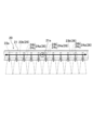
- FIGS. 1 and 2 show a machine tool 1 equipped with a fluid nozzle 20 of the embodiment.
- This machine tool 1 is a horizontal machining center and includes a bed 2, a column 3, a spindle head 5, a spindle 6, a table 7, and a protective cover 9, and the fluid nozzle 20 ejects coolant along the protective cover 9 of the machine tool 1 as described below (see the two-dot chain lines in FIGS. 1 and 2). Note that in FIGS. 1 and 2, which show the entire machine tool 1, only the main components in this embodiment are shown.
- the bed 2 is composed of a linear first bed 2a and a linear second bed 2b connected perpendicularly to the first bed 2a, and has an overall T-shape in a plan view.
- the table 7 is disposed on the second bed 2b and is guided by a guide rail 8 to move forward and backward relative to the first bed 2a, i.e., in the horizontal direction of the arrow Z.
- the column 3 is disposed on the first bed 2a (see FIG. 2) and is guided by guide rails 4 so as to move in the direction of the X-axis (the direction perpendicular to the plane of the paper in FIG. 2) which is horizontally perpendicular to the Z-axis.
- the spindle head 5 rotatably supports the spindle 6 and is held by the column 3 so as to be movable in the vertical Y-axis direction which is perpendicular to the X-axis and Z-axis.
- the spindle head 5 moves within the X-axis-Y-axis plane.
- the protective cover 9 is composed of multiple cover bodies 9a (see Figure 1) connected by a pantograph mechanism (not shown) provided on the back side of the cover bodies.
- the protective cover 9 is attached to a frame-shaped sheet metal frame 15 erected on the first bed 2a, and is positioned so as to separate the base end side of the column 3 and spindle head 5 from the machining area (the area above the second bed 2b).
- the fluid nozzle 20 is arranged on the front side of the upper end of the sheet metal frame 15 with a small gap therebetween, and extends in the X-axis direction as viewed from the front side of the machine tool 1.
- the fluid nozzle 20 is inclined at approximately 45° with respect to the vertical direction (Y-axis direction) so that the lower end edge is located rearward of the upper end edge as viewed from the X-axis direction.
- the fluid nozzle 20 is fixed to the sheet metal frame 15 with bolts via L-shaped brackets (not shown) provided at both ends in the longitudinal direction.
- the fluid nozzle 20 then flows the coolant supplied from the coolant supply device 10 (see FIG. 2) installed on the rear side of the machine tool 1 downward along the front side of the protective cover 9.
- the coolant that reaches the lower end of the protective cover 9 flows downward from the upper surface of the second bed 2b, and then returns to the coolant tank 11 of the coolant supply device 10 through the return pipe 13.
- the coolant supply device 10 filters the returned coolant, and supplies the filtered coolant again to the fluid nozzle 20 from the supply pipe 14 by the power of the coolant pump 12. In this way, the coolant flows along a series of circulation paths (see the arrows in FIG. 2) that pass through the coolant supply device 10 and the fluid nozzle 20.
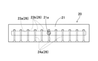
- the fluid nozzle 20 has a flat rectangular shape in an overall view and is disposed vertically so that its thickness direction faces the horizontal direction (Z-axis direction in this example).
- a coolant supply hole 21a (corresponding to a fluid supply hole) is formed on the front side surface of the fluid nozzle 20.
- the fluid nozzle 20 is disposed with the coolant supply hole 21a facing the back side of the machine tool 1 (see Fig. 1).
- the fluid nozzle 20 is configured to branch the coolant supplied from the coolant supply hole 21a into multiple branches and then discharge them from the lower end surface of the nozzle.
- the fluid nozzle 20 is constructed by stacking four plate materials 21 to 24 in the plate thickness direction.
- Each plate material 21 to 24 has a rectangular shape when viewed in the plate thickness direction and is made of a metal material such as aluminum, and each plate material is bonded to each other with an adhesive. Note that it is not necessary to use an adhesive to bond each plate material to each other, and it may be possible to use only bolt fastening, for example.
- the four plate materials 21 to 24 consist of a front plate material 21, a rear plate material 22 arranged on the rear side of the front plate material 21, and a first intermediate plate material 23 and a second intermediate plate material 24 arranged between the front plate material 21 and the rear plate material 22.
- the first intermediate plate material 23 and the second intermediate plate material 24 are arranged in this order from the front side to the rear side of the fluid nozzle 20.
- the front plate material 21 has the coolant supply hole 21a in the center in the longitudinal direction.
- the coolant supply hole 21a is a circular hole into which the screw-in type pipe joint 25 is screwed.
- the supply pipe 14 is connected to the pipe joint 25, and the coolant from the coolant supply device 10 is supplied to the coolant supply hole 21a via this supply pipe 14.
- the first and second intermediate plate members 23, 24 are formed with a fluid passage 26 through which the coolant supplied from the coolant supply hole 21a flows.
- This fluid passage 26 is composed of an inlet opening 23a and multiple inlet cutouts 23b formed in the first intermediate plate 23, and multiple outlet cutouts 24a formed in the second intermediate plate 24.
- each discharge notch 24a is formed to extend in the vertical direction (the vertical direction of the second intermediate plate 24 in this example) and open to the bottom. More specifically, as shown in Fig. 6, each discharge notch 24a is composed of a slit-shaped straight portion 24b extending in the vertical direction and a flared portion 24c connected to the lower end of the straight portion 24b. The flared portion 24c is formed so that the flow path width (the dimension in the flow path width direction perpendicular to the plate thickness direction) becomes wider from the top to the bottom.
- the flared portion 24c is formed so that the flow path width becomes wider from the upstream side to the downstream side in the coolant discharge direction.
- the flow path width at the upper end position of the flared portion 24c is equal to the flow path width of the straight portion 24b.
- the divergence angle ⁇ of the divergent portion 24c as viewed in the plate thickness direction is set to, for example, 120° or more and 150° or less.
- the introduction opening 23a is a rectangular opening formed over the entire longitudinal direction of the first intermediate plate 23.
- the introduction opening 23a is formed across the multiple discharge notches 24a.
- the introduction opening 23a is formed so that its upper edge is located slightly above the upper end position of the straight portion 24b of the discharge notch 24a, and its lower edge is located above the lower end position of the straight portion 24b.
- the introduction opening 23a is formed so as to overlap a part of the upper end side of the straight portion 24b of each discharge notch 24a (in this example, a range of approximately 2/3 of the upper end side of the straight portion 24b).
- each introduction notch 23b is formed in a U-shape (an example of a concave shape) that opens toward the introduction opening 23a (upper side in this example).
- each introduction notch 23b is formed so as to overlap with a part of each discharge notch 24a formed in the second intermediate plate material 24 when viewed from the plate thickness direction. More specifically, each introduction notch 23b is formed so as to overlap with the lower end of the straight portion 24b in each discharge notch 24a when viewed from the plate thickness direction.
- each introduction notch 23b in the width direction coincides with both ends of each discharge notch 24a in the width direction when viewed from the plate thickness direction.
- the lower end position of each introduction notch 23b coincides with the upper end position of the flared portion 24c in each discharge notch 24a.
- FIG. 8 is an explanatory diagram for explaining the coolant flow path in the fluid nozzle 20.
- the coolant supplied to the coolant supply hole 21a from the front side of the fluid nozzle 20 spreads to both sides in the left and right direction of FIG. 8 so as to fill the space inside the introduction opening 23a formed in the first intermediate plate material 23.
- This spread coolant flows from the introduction opening 23a into each discharge notch 24a, and is then discharged in a film form from the flared portion 24c at the lower end of each discharge notch 24a (see the two-dot chain line in FIG. 8).
- the reason why this reduction in piping is possible will be explained based on a comparison with a comparative fluid nozzle 120 shown in Figure 9.
- the comparative fluid nozzle 120 differs from this embodiment in that it does not have multiple introduction notches 23b, but the rest of the configuration is the same as this embodiment.
- the same components as in the embodiment are indicated by the reference numerals used in the embodiment with 100 added.
- the introduction notch 23b formed in the first intermediate plate 23 communicates with the straight portion 24b of each discharge notch 24a, thereby ensuring a flow passage thickness ta equivalent to two plate thicknesses.
- the flow passage thickness is sufficiently ensured when the coolant flows from the introduction opening 23a into the lower flow passage portion 24d of the discharge notch 24a, thereby reducing the pipeline resistance. This prevents the amount of coolant flowing into the lower flow passage portion 24d of the discharge notch 24a from becoming insufficient, and in turn ensures that the coolant can be discharged from the lower end of each discharge notch 24a at the desired flow rate and shape.
- each discharge notch 24a is a diverging portion 24c whose dimension in the flow path width direction increases from the upstream side to the downstream side in the fluid discharge direction (from the top to the bottom in Figure 6).
- each discharge notch 24a spreads in the flow path width direction along the inner wall surface of the flared portion 24c and is discharged in the form of a film. Therefore, the coolant discharge range can be expanded over a wider area than when the coolant is discharged in a line from each discharge notch 24a (see FIG. 8). This in turn increases the cleaning effect of the protective cover 9 by the coolant as much as possible.
- each inlet notch 23b is located at the same height as the upper end of the flared portion 24c of each outlet notch 24a (see Figures 6 and 7).
- the coolant introduced into each introduction notch 23b through the introduction opening 23a can be supplied to the portion of each discharge notch 24a above the flared portion 24c. Therefore, the coolant can be smoothly spread over the entire area from the upper end to the lower end of the flared portion 24c without peeling. This ensures that the coolant can be spread over the flared portion 24c.
- each discharge notch 24a to the flared portion 24c is a straight section 24b consisting of a straight slit hole.
- the outer edge shape of the fluid nozzle 20 is rectangular, but this is not limited thereto and may be any shape, such as circular or triangular.
- Fig. 10 shows an embodiment in which both ends of the lower edge of the fluid nozzle 20 are chamfered to form a non-rectangular shape. Note that in Fig. 10 and Fig. 11 described later, the same components as those in the above embodiment are denoted by the same reference numerals.
- the fluid nozzle 20 is inclined at approximately 45° with respect to the vertical direction (Y-axis direction) so that the lower edge is located behind the upper edge when viewed from the X-axis direction, but this is not limited to this. That is, the inclination angle of the fluid nozzle 20 may be greater than 45° or less than 45°.
- the fluid nozzle 20 may also be arranged horizontally or vertically without being inclined when viewed from the X-axis direction. Also, for example, when supplying coolant to the surface of the workpiece W located in the processing area, the fluid nozzle 20 may be inclined so that its lower edge is located forward of its upper edge.
- each introduction notch 23b formed in the first intermediate plate 23 is formed in a U-shape that opens toward the introduction opening 23a, but this is not limited thereto and may be formed, for example, in a semicircular or triangular shape.
- each of the inlet notches 23b formed in the first intermediate plate 23 is formed so as to overlap a portion of each of the discharge notches 24a that is located below the inlet opening 23a when viewed from the plate thickness direction, but this is not limited thereto, and for example, as shown in FIG. 11, each of the discharge notches 24a may be formed so as to overlap a portion of each of the discharge notches 24a that is located above the inlet opening 23a.
- each of the inlet notches 23b may have any configuration as long as it is formed so as to overlap a portion of each of the discharge notches 24a when viewed from the plate thickness direction.
- the discharge notches 24a are formed at intervals from one another along one edge side (lower edge side) of the second intermediate plate 24, but this is not limited thereto, and for example, the discharge notches 24a may be formed at intervals from one another along the entire edge of the second intermediate plate 24. This makes it possible to discharge fluid from the entire peripheral side surface of the fluid nozzle 20, thereby expanding the range of uses of the fluid nozzle 20 in various ways.
- the lower end position of the introduction notch 23b is at the same height as the upper end position of the flared portion 24c, but this is not limited thereto, and it may be located above the upper end position of the flared portion 24c. This allows the coolant to be smoothly spread without peeling over the entire area from the upper end to the lower end of the flared portion 24c, just like in the above embodiment.
- coolant was described as an example of the fluid ejected from the fluid nozzle 20, but this is not limited thereto, and the fluid may be other liquids such as water, or may be a gas such as air.
- the fluid nozzle 20 was placed near the upper end of the sheet metal frame 15 of the machine tool 1, but this is not limited to this, and for example, the fluid nozzle 20 may be placed in a shutter opening/closing section of a tool changer provided on the machine tool 1. Furthermore, the fluid nozzle 20 can be used for a variety of purposes, such as blocking dust with a fluid and diffusing gas in an air purifier or air conditioner, rather than being limited to cleaning chips and the like.
- Fluid passage 21 Front plate material 21a Coolant supply hole (fluid supply hole) 22 Back plate 23 First intermediate plate 23a Introduction opening (fluid passage) 23b Introduction notch (fluid passage) 24 Second intermediate plate 24a Discharge notch portion (fluid passage) 24b Straight portion 24c Expanded portion 26 Fluid passage
Landscapes
- Engineering & Computer Science (AREA)
- Mechanical Engineering (AREA)
- Nozzles (AREA)
Abstract
流体ノズル(20)は、流体供給孔(21a)を有する表側板材(21)と、その裏側に配置される裏側板材(22)と、流体通路(26)が形成される第1中間板材(23)及び第2中間板材(24)とを積層して構成されている。流体通路(26)は、第1中間板材(23)に形成された導入開口(23a)及び複数の導入切欠部(23b)と、第2中間板材(24)に形成された複数の吐出切欠部(24a)とで構成されている。複数の吐出切欠部(24a)は、第2中間板材(24)の下端縁に沿って間隔を空けて並ぶとともに該下端縁側に開放している。前記導入開口部(23a)は、複数の吐出切欠部(24a)に跨がって形成され、前記各導入切欠部(23b)は、板厚方向から見て、該導入開口部(23a)側に開放する凹状をなすとともに、前記各吐出切欠部(24a)のそれぞれの一部と重複するように形成されている。
Description
本発明は、流体を吐出する流体ノズルに関する。
従来より、工作機械などに搭載され、加工中に発生する切屑の除去や摩擦熱の冷却等の目的で所定部位に流体を吐出する流体ノズルが知られている。
この種の流体ノズルでは、流体を広範囲に亘って供給するべく様々な構成が提案されている。例えば、特許文献1に示す流体ノズルでは、クーラント貯留箱に水平方向に延びるスリット状の吐出孔を形成することで、該吐出孔からクーラント(流体の一例)をカーテン状に吐出して広範囲に供給するようにしている。
しかしながら、特許文献1に示す流体ノズルでは、大型のクーラント貯留箱が必要になるので設置位置が制限されるという問題がある。
また、クーラント貯留箱の長手方向の全体に亘ってスリット状の吐出孔を形成するようにしているので、クーラント貯留箱に供給するクーラント(流体)の流量が少ないと、吐出孔から吐出されるクーラントをカーテン状に上手く拡散させることができないという問題がある。この問題を回避するために、クーラント貯留箱にクーラントを供給するポンプの大型化を図ってクーラントの供給流量を増加させることが考えられる。しかし、この場合、大型のポンプが必要となるためコスト増加を招いてしまう。
本発明は、以上の実情に鑑みてなされたものであって、コンパクトで且つ安価な構成により、流体を広範囲に亘って確実に吐出可能な流体ノズルを提供することを、その目的とする。
本発明の一局面は、
流体を吐出する流体ノズルであって、
当該流体ノズルは、複数の板材を板厚方向に積層して構成され、
前記複数の板材は、
前記板厚方向に貫通する流体供給孔を有する表側板材と、
前記表側板材の裏側に配置される裏側板材と、
前記表側板材及び前記裏側板材間において前記板厚方向の表側から裏側に向かって順に配置され、流体通路が形成される第1中間板材及び第2中間板材とを含み、
前記第2中間板材は、その外縁に沿って互いに間隔を空けて並んで配置され且つ該外縁側に開放する複数の吐出切欠部を有し、
前記第1中間板材は、前記板厚方向から見て前記第2中間板材に形成された前記複数の吐出切欠部に跨がって形成され、前記流体供給孔から供給される流体を受け入れて前記各吐出切欠部に導く導入開口部と、該導入開口部の外縁に接続され、前記板厚方向から見て該導入開口部側に開放する凹状をなすとともに前記複数の吐出切欠部のそれぞれの一部と重複する複数の導入切欠部とを有し、
前記導入開口部、前記複数の導入切欠部、及び前記複数の吐出切欠部が前記流体通路を構成している流体ノズルに係る。
この流体ノズルによれば、表側板材に形成された流体供給口から供給された流体は、先ず、第1中間板材に形成された導入開口部に導入されて、該導入開口部の全体に亘って広がる。この導入開口部は、板厚方向から見て、第2中間板材に形成された複数の吐出切欠部に跨がって形成されているので、導入開口部内に供給された流体は各吐出切欠部に供給され、各吐出切欠部の開放側の端部から外部に吐出される。ここで、導入開口部の外縁には、該導入開口部側に開放する凹状をなすとともに各吐出切欠部のそれぞれの一部と重複する複数の導入切欠部が形成されているので、導入開口部から各吐出切欠部への流体の供給を円滑に行い、延いては、各吐出切欠部からの流体の吐出流量を十分に確保することができる。
すなわち、本発明のように板材を積層した積層型の流体ノズルでは、ノズル全体を薄型化してスペース効率を向上することができる反面、ノズル内部の流体通路、つまり導入開口部及び各吐出切欠部の通路断面積が狭くなって流体の流れが悪くなる。特に、導入開口部から各吐出切欠部へと流体が供給される際には、流路面積が急激に絞られることにより管路抵抗が増加し、導入開口部から各吐出切欠部への流体の供給量が不足する虞がある。これに対して本発明の流体ノズルでは、第1中間板材に、板厚方向から見て各吐出切欠部のそれぞれの一部と重複する複数の導入切欠部を形成するようにしたことで、導入開口部から各吐出切欠部に流体が流入する際の流路断面積を第1中間板材の板厚1枚分だけ余分に確保することができる。よって、流体が導入開口部から各吐出切欠部に流入する際の管路抵抗を低減して流体の流量を十分に確保することができる。
前記各吐出切欠部の開放側の端部は、流体吐出方向の上流側から下流側に向かうにしたがって板厚方向に直交する流路幅方向の寸法が増加する末広がり部とされている構成を採用することが好ましい。
この構成によれば、各吐出切欠部の開放側の端部において、流体が末広がり部の内壁面に沿って流路幅方向に広がって膜状に吐出される。したがって、例えば、各吐出切欠部から流体が線状に吐出される場合に比べて流体の吐出範囲を広く確保することができる。
前記表側板材、前記裏側板材、並びに、前記第1中間板材及び第2中間板材は、鉛直に配置されており、前記各吐出切欠部は下側に開放するように形成され、前記各導入切欠部の下端位置は、前記各吐出切欠部の前記末広がり部の上端位置と同じ高さか又は該上端位置よりも上側に位置している構成を採用することができる。
この構成によれば、各導入切欠部の下端位置を各吐出切欠部の末広がり部の上端位置と同じ高さか又はそれよりも上側に位置させるようにしたことで、導入開口部を通じて各導入切欠部に導入された流体を、各吐出切欠部における末広がり部よりも上側の部分に供給することができる。したがって、流体を末広がり部の上端から下端に亘る全域において剥離なくスムーズに拡幅することができる。よって、末広がり部における流体の拡幅効果を確実に得ることができる
前記各吐出切欠部の基端部から前記末広がり部に至るまでの部分は、直線状のスリット孔からなる直線部とされている構成を採用することができる。
この構成によれば、スリット状の直線部にて流体の流速を十分に高めた上で、当該流体を末広がり部に導入することができる。よって、末広がり部に流入する流体の流速を十分に確保し、延いては末広がり部における流体の拡幅効果を確実に得ることができる。
本発明は、以上の実情に鑑みてなされたものであって、表側板材と裏側板材と該両板材の間に位置する第1中間板材及び第2中間板材とを積層して流体ノズルを構成し、第2中間板材には、その外縁に沿って並ぶとともに該外縁側に開放する複数の吐出切欠部を形成し、第1中間板材には、前記板厚方向から見て前記第2中間板材に形成された前記複数の吐出切欠部に跨がって形成され、流体供給孔から供給される流体を受け入れて前記各吐出切欠部に導く導入開口部と、該導入開口部の外縁に接続され、板厚方向から見て該導入開口部側に開放する凹状をなすとともに前記複数の吐出切欠部のそれぞれの一部と重複する複数の導入切欠部とを形成するようにしたことで、コンパクトで且つ安価な構成により、流体を広範囲に亘って確実に吐出することができる。
以下、本発明の一実施形態について、図面を参照しながら説明する。
《実施形態》
図1及び図2は、実施形態の流体ノズル20を備えた工作機械1を示している。この工作機械1は、横型のマシニングセンタであって、ベッド2、コラム3、主軸頭5、主軸6、テーブル7、及び保護カバー9などを備えており、流体ノズル20は、後述するように工作機械1の保護カバー9に沿ってクーラントを吐出する(図1及び図2の二点鎖線参照)。尚、工作機械1の全体を示す図1及び図2では、本実施形態において主要な構成となる要素のみを図示している。
図1及び図2は、実施形態の流体ノズル20を備えた工作機械1を示している。この工作機械1は、横型のマシニングセンタであって、ベッド2、コラム3、主軸頭5、主軸6、テーブル7、及び保護カバー9などを備えており、流体ノズル20は、後述するように工作機械1の保護カバー9に沿ってクーラントを吐出する(図1及び図2の二点鎖線参照)。尚、工作機械1の全体を示す図1及び図2では、本実施形態において主要な構成となる要素のみを図示している。
前記ベッド2は、直線状をした第1ベッド2a、及びこの第1ベッド2aに直交するように連結された同じく直線状をした第2ベッド2bから構成され、全体として平面視T字形状を備えている。前記テーブル7は前記第2ベッド2b上に配設され、ガイドレール8に案内されて前記第1ベッド2aに対して進退、即ち、水平な矢示Z軸方向に移動するように設けられている。
前記コラム3は、前記第1ベッド2a上に配設され(図2参照)、ガイドレール4に案内されて、前記Z軸と水平に直交する矢示X軸方向(図2の紙面垂直方向)に移動するように設けられている。また、前記主軸頭5は、主軸6を回転自在に支持し、前記X軸及びZ軸に直交する鉛直なY軸方向に移動可能に前記コラム3に保持されている。斯くして、主軸頭5はX軸-Y軸平面内で移動する。
保護カバー9は、複数のカバー体9a(図1参照)をその背面側に設けられたパンタグラフ機構(図示省略)により連結して構成されている。保護カバー9は、第1ベッド2a上に立設された枠状の板金フレーム15に取付けられて、コラム3及び主軸頭5の基端側部分を加工領域(第2ベッド2bよりも上側の領域)から隔てるように配置されている。
前記流体ノズル20は、板金フレーム15の上端部の前側面に僅かに隙間を空けて配置されていて、工作機械1の正面側から見てX軸方向に延設されている。流体ノズル20は、X軸方向から見て、下端縁が上端縁よりも後側に位置するように鉛直方向(Y軸方向)に対して略45°で傾斜している。流体ノズル20は、長手方向の両端部に設けられた不図示のL字ブラケットを介して板金フレーム15にボルトで固定されている。そして、流体ノズル20は、工作機械1の背面側に設置されたクーラント供給装置10(図2参照)から供給されたクーラントを保護カバー9の前側面に沿って下方へと流通させる。これにより、保護カバー9の前側面に付着した切屑などの異物がクーラントによって洗浄除去される。保護カバー9の下端に達したクーラントは、第2ベッド2bの上面からその下方に流れた後、戻り管13を通ってクーラント供給装置10のクーラントタンク11に還流される。クーラント供給装置10では、還流されたクーラントを濾過するとともに、濾過後のクーラントを、クーラントポンプ12の動力によって、供給管14から流体ノズル20に再度供給する。こうして、クーラント供給装置10と流体ノズル20とを経由する一連の循環経路(図2中の矢印参照)に沿ってクーラントが流通するようになっている。
[流体ノズルの構成]
図3に示すように、前記流体ノズル20は、全体視で偏平な矩形状をなしていて、その厚さ方向が水平方向(本例ではZ軸方向)を向くように鉛直に配置されている。流体ノズル20の表側面にはクーラント供給孔21a(流体供給孔に相当)が形成されている。流体ノズル20は、このクーラント供給孔21aを工作機械1の背面側に向けた状態で配置されている(図1参照)。流体ノズル20は、クーラント供給孔21aから供給されるクーラントを複数に分岐させた後、ノズル下端面から吐出するように構成されている。
図3に示すように、前記流体ノズル20は、全体視で偏平な矩形状をなしていて、その厚さ方向が水平方向(本例ではZ軸方向)を向くように鉛直に配置されている。流体ノズル20の表側面にはクーラント供給孔21a(流体供給孔に相当)が形成されている。流体ノズル20は、このクーラント供給孔21aを工作機械1の背面側に向けた状態で配置されている(図1参照)。流体ノズル20は、クーラント供給孔21aから供給されるクーラントを複数に分岐させた後、ノズル下端面から吐出するように構成されている。
具体的には、流体ノズル20は、図4に示すように、4つの板材21~24を板厚方向に積層して構成されている。各板材21~24は、板厚方向から見て矩形状をなしていて例えばアルミニウムなどの金属材料により構成され、各板材同士は接着剤により接合されている。尚、各板材同士の接合には、必ずしも接着剤を用いる必要はなく例えばボルト締結のみで行うようにしてもよい。
4つの板材21~24は、表側板材21と、表側板材21の裏側に配置された裏側板材22と、表側板材21及び裏側板材22の間に配置された第1中間板材23及び第2中間板材24とからなる。第1中間板材23及び第2中間板材24は、流体ノズル20の表側から裏側に向かってこの順に配置されている。
表側板材21は、長手方向の中央部に前記クーラント供給孔21aを有している。クーラント供給孔21aは円孔状をなしており、該クーラント供給孔21aには該螺子込み式の管継ぎ手25が螺合している。管継ぎ手25には前記供給管14が接続されており、クーラント供給装置10からのクーラントがこの供給管14を介してクーラント供給孔21aに供給される。
前記第1及び第2中間板材23,24には、クーラント供給孔21aから供給されたクーラントが流通する流体通路26が形成されている。
この流体通路26は、第1中間板材23に形成された導入開口部23a及び複数の導入切欠部23bと、第2中間板材24に形成された複数の吐出切欠部24aとで構成されている。
複数の吐出切欠部24aは、図4及び図5に示すように、第2中間板材24の下端縁に沿って互いに間隔を空けて並ぶとともに、この下端縁に沿った長手方向の略全体に亘って配置されている。各吐出切欠部24aは、上下方向(本例では第2中間板材24の縦方向)に延びるとともに下側に開放するように形成されている。より詳細には、各吐出切欠部24aは、図6に示すように、上下方向に延びるスリット孔状の直線部24bと、直線部24bの下端部に接続された末広がり部24cとで構成されている。末広がり部24cは、上側から下側に向かうほど流路幅(板厚方向に直交する流路幅方向の寸法)が広くなるように形成されている。換言すると、末広がり部24cは、クーラント吐出方向の上流側から下流側に向かうほど流路幅が広くなるように形成されている。末広がり部24cの上端位置における流路幅は、直線部24bの流路幅に等しい。末広がり部24cの板厚方向から見た広がり角θは、例えば120°以上150°以下に設定されている。
前記導入開口部23aは、図5に示すように、第1中間板材23の長手方向の全体に亘って形成された矩形状の開口部である。導入開口部23aは、板厚方向から見て、前記複数の吐出切欠部24aに跨って形成されている。図5及び図6に示すように、導入開口部23aは、上端縁が、吐出切欠部24aの直線部24bの上端位置よりも僅かに上側に位置し、下端縁が、該直線部24bの下端位置よりも上側に位置するように形成されている。そうして、導入開口部23aは、板厚方向から見て、各吐出切欠部24aの直線部24bの上端側の一部(本例では、直線部24bの上端側の略2/3の範囲)と重複するように形成されている。
前記複数の導入切欠部23bは、図4に示すように、導入開口部23aの下端縁に沿って互いに間隔を空けて並んでいる。各導入切欠部23bは、該導入開口部23a側(本例では上側)に開放するコ字状(凹状の一例)に形成されている。図6に示すように、各導入切欠部23bは、板厚方向から見て、第2中間板材24に形成された各吐出切欠部24aのそれぞれの一部と重複するように形成されている。より具体的には、各導入切欠部23bは、板厚方向から見て、各吐出切欠部24aにおける直線部24bの下端部と重複するように形成されている。各導入切欠部23bの幅方向の両端縁は、板厚方向から見て、各吐出切欠部24aの幅方向の両端縁に一致している。図7に示すように、各導入切欠部23bの下端位置は、各吐出切欠部24aにおける末広がり部24cの上端位置に一致している。
図8は、前記流体ノズル20におけるクーラントの流通経路を説明するための説明図である。図中の実線矢印で示すように、流体ノズル20の表側(図8の紙面手前側)からクーラント供給孔21aに供給されたクーラントは、第1中間板材23に形成された導入開口部23a内の空間を満たすように、図8の左右方向の両側に広がる。この広がったクーラントは、導入開口部23aから各吐出切欠部24aに流入した後、各吐出切欠部24aの下端部の末広がり部24cから膜状に吐出される(図8の二点鎖線参照)。
ここで、クーラントが導入開口部23aから各吐出切欠部24aに流入する際には、流路断面積が急激に変化するため管路抵抗が増加し、各吐出切欠部24aに流入するクーラントの流量が不足する虞がある。これに対して、本実施形態では、上述したように板厚方向から見て各吐出切欠部24aと重複する複数の導入切欠部23bを第1中間板材23に設けることで管路抵抗の低減を図っている。
この管路低減が図れる理由を、図9に示す比較例の流体ノズル120との比較を基に説明する。比較例に係る流体ノズル120は、複数の導入切欠部23bを有さない点で本実施形態と異なるが、その他の構成は本実施形態と同様である。図9において、実施形態と同じ構成要素には、実施形態で使用した符号に100を加算して示している。
この比較例の流体ノズル120では、吐出切欠部124aのうち導入開口部123aよりも下側に位置する下側流路部分124d(つまり吐出切欠部124aのうち導入開口部123aからのクーラントが向かう先の部分)において、板厚1枚分の流路厚さtbしか確保されていない。これに対して、本実施形態の流体ノズル20では、図7に示すように、下側流路部分24dにおいて、第1中間板材23に形成された導入切欠部23bと各吐出切欠部24aの直線部24bとが連通することにより板厚2枚分の流路厚さtaが確保されている。したがって、本実施形態の流体ノズル20では、比較例の流体ノズル120に比べて、クーラントが導入開口部23aから、吐出切欠部24aの下側流路部分24dに流入する際の流路厚さを十分に確保して管路抵抗を低減することができる。よって、吐出切欠部24aの下側流路部分24dへのクーラントの流入量が不足するのを防止し、延いては、各吐出切欠部24aの下端部からクーラントを所望の流量及び形状で確実に吐出させることができる。
また、本実施形態では、各吐出切欠部24aの開放側の端部は、流体吐出方向の上流側から下流側(図6の上側から下側)に向かうにしたがって流路幅方向の寸法が増加する末広がり部24cとされている。
これによれば、各吐出切欠部24aの開放側の端部に到達したクーラントは、末広がり部24cの内壁面に沿って流路幅方向に広がって膜状に吐出される。したがって、例えば、各吐出切欠部24aからクーラントが線状に吐出される場合に比べてクーラントの吐出範囲を広範囲に広げることができる(図8参照)。延いては、クーラントによる保護カバー9の洗浄効果を可及的に高めることができる。
また、各導入切欠部23bの下端位置は、各吐出切欠部24aの末広がり部24cの上端位置と同じ高さに位置している(図6及び図7参照)。
これによれば、導入開口部23aを通じて各導入切欠部23bに導入されたクーラントを、各吐出切欠部24aにおける末広がり部24cよりも上側の部分に供給することができる。したがって、クーラントを末広がり部24cの上端から下端に亘る全域で剥離なくスムーズに拡幅することができる。よって、末広がり部24cにおけるクーラントの拡幅効果を確実に得ることができる。
前記各吐出切欠部24aの基端部から末広がり部24cに至るまでの部分は、直線状のスリット孔からなる直線部24bとされている。
これによれば、スリット状の直線部24bにてクーラントの流速を十分に高めた上で、当該クーラントを末広がり部24cに導入することができる。よって、末広がり部24cに流入するクーラントの流速を十分に確保し、延いては末広がり部24cにおけるクーラントの拡幅効果を確実に得ることができる。
《他の実施形態》
前記実施形態では、流体ノズル20の外縁形状は矩形状とされているが、これに限ったものではなく、例えば、円形状や三角形状など如何なる形状であってもよい。一例として、図10には、流体ノズル20の下端縁の両端部を面取りした非矩形状の実施例を示している。尚、図10及び後述する図11において前記実施形態と同じ構成要素には同じ符号を付している。
前記実施形態では、流体ノズル20の外縁形状は矩形状とされているが、これに限ったものではなく、例えば、円形状や三角形状など如何なる形状であってもよい。一例として、図10には、流体ノズル20の下端縁の両端部を面取りした非矩形状の実施例を示している。尚、図10及び後述する図11において前記実施形態と同じ構成要素には同じ符号を付している。
前記実施形態では、流体ノズル20は、X軸方向から見て下端縁が上端縁よりも後側に位置するように鉛直方向(Y軸方向)に対して略45°で傾斜しているが、これに限ったものではない。すなわち、流体ノズル20の傾斜角は45°を超えてもよいし、45°未満であってもよい。また、流体ノズル20をX軸方向から見て傾斜させずに水平に又は鉛直に配置するようにしてもよい。また、例えば、加工エリア内に位置するワークWの表面にクーラントを供給する場合には、流体ノズル20をその下端縁が上端縁よりも前側に位置するように傾斜させてもよい。
前記実施形態では、第1中間板材23に形成される各導入切欠部23bは、導入開口部23a側に開放するコ字状に形成されているが、これに限ったものではなく、例えば半円状や三角形状に形成されていてもよい。
前記実施形態では、第1中間板材23に形成される各導入切欠部23bは、板厚方向から見て、各吐出切欠部24aにおける導入開口部23aよりも下側に位置する部分に重複するように形成されているが、これに限ったものではなく、例えば図11に示すように、各吐出切欠部24aにおける導入開口部23aよりも上側に位置する部分に重複するように形成されていてもよい。すなわち、各導入切欠部23bは、板厚方向から見て、各吐出切欠部24aのそれぞれの一部と重複するように形成されていれば如何なる構成であってもよい。この構成を採用することで、クーラントが導入開口部23aから各吐出切欠部24aに流入する際の板厚方向の流路厚さを増加させて前記実施形態と同様の作用効果を得ることができる。
前記実施形態では、各吐出切欠部24aは、第2中間板材24の一端縁側(下端縁側)に沿って互いに間隔を空けて形成されているが、これに限ったものではなく、例えば、第2中間板材24の全縁に沿って互いに間隔を空けて形成されていてもよい。これにより、流体ノズル20の周側面の全体から流体を吐出可能になるので、流体ノズル20の用途を様々に拡大することができる。
前記実施形態では、導入切欠部23bの下端位置は、末広がり部24cの上端位置と同じ高さとされているが、これに限ったものではなく、末広がり部24cの上端位置よりも上側に位置していてもよい。これにより、前記実施形態と同様に、末広がり部24cの上端から下端に亘る全域においてクーラントを剥離なくスムーズに拡幅することができる。
前記実施形態では、流体ノズル20から吐出する流体の一例としてクーラントを挙げて説明したが、これに限ったものではなく、流体は水などの他の液体であってもよいし、空気などの気体であってもよい。
前記実施形態では、流体ノズル20を工作機械1の板金フレーム15の上端部付近に配置した例を説明したが、これに限ったものではなく、例えば工作機械1に設けられる工具交換装置のシャッタ開閉部に設けるようにしてもよい。また、流体ノズル20は、切屑などの洗浄用に限らず、流体による粉塵の遮断や、空気清浄機やエアコンによる気体の拡散用など、様々な用途に使用することができる。
尚、上述した実施形態の説明は、すべての点で例示であって、制限的なものではない。当業者にとって変形及び変更が適宜可能である。本発明の範囲は、上述の実施形態ではなく、特許請求の範囲によって示される。さらに、本発明の範囲には、特許請求の範囲内と均等の範囲内での実施形態からの変更が含まれる。
20 流体ノズル
21 表側板材
21a クーラント供給孔(流体供給孔)
22 裏側板材
23 第1中間板材
23a 導入開口部(流体通路)
23b 導入切欠部(流体通路)
24 第2中間板材
24a 各吐出切欠部(流体通路)
24b 直線部
24c 末広がり部
26 流体通路
21 表側板材
21a クーラント供給孔(流体供給孔)
22 裏側板材
23 第1中間板材
23a 導入開口部(流体通路)
23b 導入切欠部(流体通路)
24 第2中間板材
24a 各吐出切欠部(流体通路)
24b 直線部
24c 末広がり部
26 流体通路
Claims (4)
- 流体を吐出する流体ノズルであって、
当該流体ノズルは、複数の板材を板厚方向に積層して構成され、
前記複数の板材は、
前記板厚方向に貫通する流体供給孔を有する表側板材と、
前記表側板材の裏側に配置される裏側板材と、
前記表側板材及び前記裏側板材間において前記板厚方向の表側から裏側に向かって順に配置され、流体通路が形成される第1中間板材及び第2中間板材とを含み、
前記第2中間板材は、その外縁に沿って互いに間隔を空けて並んで配置され且つ該外縁側に開放する複数の吐出切欠部を有し、
前記第1中間板材は、前記板厚方向から見て前記第2中間板材に形成された前記複数の吐出切欠部に跨がって形成され、前記流体供給孔から供給される流体を受け入れて前記各吐出切欠部に導く導入開口部と、該導入開口部の外縁に接続され、前記板厚方向から見て該導入開口部側に開放する凹状をなすとともに前記複数の吐出切欠部のそれぞれの一部と重複する複数の導入切欠部とを有し、
前記導入開口部、前記複数の導入切欠部、及び前記複数の吐出切欠部が前記流体通路を構成していることを特徴とする流体ノズル。 - 前記各吐出切欠部の開放側の端部は、流体吐出方向の上流側から下流側に向かうにしたがって、前記板厚方向に直交する流路幅方向の寸法が増加する末広がり部とされていることを特徴とする請求項1記載の流体ノズル。
- 前記表側板材、前記裏側板材、並びに、前記第1中間板材及び前記第2中間板材は、鉛直に配置されており、
前記各吐出切欠部は下側に開放するように形成され、
前記各導入切欠部の下端位置は、前記各吐出切欠部の前記末広がり部の上端位置と同じ高さか又は該上端位置よりも上側に位置していることを特徴とする請求項2記載の流体ノズル。 - 前記各吐出切欠部の基端部から前記末広がり部に至るまでの部分は、直線状のスリット孔からなる直線部とされていることを特徴とする請求項2又は3記載の流体ノズル。
Priority Applications (1)
| Application Number | Priority Date | Filing Date | Title |
|---|---|---|---|
| PCT/JP2022/045075 WO2024121966A1 (ja) | 2022-12-07 | 2022-12-07 | 流体ノズル |
Applications Claiming Priority (1)
| Application Number | Priority Date | Filing Date | Title |
|---|---|---|---|
| PCT/JP2022/045075 WO2024121966A1 (ja) | 2022-12-07 | 2022-12-07 | 流体ノズル |
Publications (1)
| Publication Number | Publication Date |
|---|---|
| WO2024121966A1 true WO2024121966A1 (ja) | 2024-06-13 |
Family
ID=91378949
Family Applications (1)
| Application Number | Title | Priority Date | Filing Date |
|---|---|---|---|
| PCT/JP2022/045075 WO2024121966A1 (ja) | 2022-12-07 | 2022-12-07 | 流体ノズル |
Country Status (1)
| Country | Link |
|---|---|
| WO (1) | WO2024121966A1 (ja) |
Citations (5)
| Publication number | Priority date | Publication date | Assignee | Title |
|---|---|---|---|---|
| JPS56102657U (ja) * | 1980-01-08 | 1981-08-12 | ||
| JP2000334333A (ja) * | 1999-05-31 | 2000-12-05 | Daiko Kennetsu Kk | 流体の整流機構 |
| JP2006281767A (ja) * | 2005-03-09 | 2006-10-19 | Ricoh Co Ltd | 液体吐出ヘッド及びその製造方法、画像形成装置、液滴を吐出する装置、記録方法 |
| JP2008080464A (ja) * | 2006-09-28 | 2008-04-10 | Masayoshi Watabe | 液体カーテン生成装置及びその生成方法 |
| JP2021061389A (ja) * | 2019-10-04 | 2021-04-15 | 株式会社荏原製作所 | ノズル及び基板洗浄装置 |
-
2022
- 2022-12-07 WO PCT/JP2022/045075 patent/WO2024121966A1/ja unknown
Patent Citations (5)
| Publication number | Priority date | Publication date | Assignee | Title |
|---|---|---|---|---|
| JPS56102657U (ja) * | 1980-01-08 | 1981-08-12 | ||
| JP2000334333A (ja) * | 1999-05-31 | 2000-12-05 | Daiko Kennetsu Kk | 流体の整流機構 |
| JP2006281767A (ja) * | 2005-03-09 | 2006-10-19 | Ricoh Co Ltd | 液体吐出ヘッド及びその製造方法、画像形成装置、液滴を吐出する装置、記録方法 |
| JP2008080464A (ja) * | 2006-09-28 | 2008-04-10 | Masayoshi Watabe | 液体カーテン生成装置及びその生成方法 |
| JP2021061389A (ja) * | 2019-10-04 | 2021-04-15 | 株式会社荏原製作所 | ノズル及び基板洗浄装置 |
Similar Documents
| Publication | Publication Date | Title |
|---|---|---|
| JP2018516760A5 (ja) | ||
| JP2005340825A5 (ja) | ||
| WO2024121966A1 (ja) | 流体ノズル | |
| US11161212B2 (en) | Laser machine for machining workpieces | |
| US20230098828A1 (en) | Manufacturing device with large-area sinking gas stream | |
| US9358668B2 (en) | Fluid jet receiving receptacles and related fluid jet cutting systems | |
| US20120175091A1 (en) | Distribution system and heat exchanger apparatus | |
| JP2002130988A (ja) | 積層型熱交換器 | |
| KR100694745B1 (ko) | 공작 기계 | |
| JP2014161971A (ja) | 切粉の排出に適したカバーを備えた工作機械 | |
| US20140241823A1 (en) | Machine tool with cover structure adapted for discharge of chips | |
| KR101203458B1 (ko) | 처리 액체로 처리 대상을 처리하는 노즐 장치 및 방법 | |
| US11794142B2 (en) | Pulse cleanable deep pleated industrial filter | |
| JP4854687B2 (ja) | 冷却装置 | |
| JP5203795B2 (ja) | 棒状部材に対するガスメタルエンクローズ溶接装置 | |
| EP2556322B1 (en) | Single-flow type integrated heat exchanger and method for cooling oil | |
| JP2011148188A (ja) | 溶融樹脂整流用ユニット | |
| JP2017113660A (ja) | 塗装ブース及び整流装置 | |
| US20200318523A1 (en) | Exhaust fluid collision type muffler | |
| JP2019184208A (ja) | 流体流路装置 | |
| JPH11101588A (ja) | プレート式熱交換器 | |
| EP0563755B1 (en) | Jet cooling apparatus for cooling electronic equipment and computer having the same mounted thereon | |
| JP4974644B2 (ja) | クーラント供給装置 | |
| JP5775381B2 (ja) | ワイヤソーの加工液ノズル | |
| US11396378B2 (en) | ECS dual entry ram inlet plenum |
Legal Events
| Date | Code | Title | Description |
|---|---|---|---|
| 121 | Ep: the epo has been informed by wipo that ep was designated in this application |
Ref document number: 22967817 Country of ref document: EP Kind code of ref document: A1 |