WO2024121966A1 - 流体ノズル - Google Patents
流体ノズル Download PDFInfo
- Publication number
- WO2024121966A1 WO2024121966A1 PCT/JP2022/045075 JP2022045075W WO2024121966A1 WO 2024121966 A1 WO2024121966 A1 WO 2024121966A1 JP 2022045075 W JP2022045075 W JP 2022045075W WO 2024121966 A1 WO2024121966 A1 WO 2024121966A1
- Authority
- WO
- WIPO (PCT)
- Prior art keywords
- fluid
- discharge
- plate
- notches
- fluid nozzle
- Prior art date
- Legal status (The legal status is an assumption and is not a legal conclusion. Google has not performed a legal analysis and makes no representation as to the accuracy of the status listed.)
- Ceased
Links
Images




Classifications
-
- B—PERFORMING OPERATIONS; TRANSPORTING
- B23—MACHINE TOOLS; METAL-WORKING NOT OTHERWISE PROVIDED FOR
- B23Q—DETAILS, COMPONENTS, OR ACCESSORIES FOR MACHINE TOOLS, e.g. ARRANGEMENTS FOR COPYING OR CONTROLLING; MACHINE TOOLS IN GENERAL CHARACTERISED BY THE CONSTRUCTION OF PARTICULAR DETAILS OR COMPONENTS; COMBINATIONS OR ASSOCIATIONS OF METAL-WORKING MACHINES, NOT DIRECTED TO A PARTICULAR RESULT
- B23Q11/00—Accessories fitted to machine tools for keeping tools or parts of the machine in good working condition or for cooling work; Safety devices specially combined with or arranged in, or specially adapted for use in connection with, machine tools
- B23Q11/0042—Devices for removing chips
- B23Q11/005—Devices for removing chips by blowing
-
- B—PERFORMING OPERATIONS; TRANSPORTING
- B23—MACHINE TOOLS; METAL-WORKING NOT OTHERWISE PROVIDED FOR
- B23Q—DETAILS, COMPONENTS, OR ACCESSORIES FOR MACHINE TOOLS, e.g. ARRANGEMENTS FOR COPYING OR CONTROLLING; MACHINE TOOLS IN GENERAL CHARACTERISED BY THE CONSTRUCTION OF PARTICULAR DETAILS OR COMPONENTS; COMBINATIONS OR ASSOCIATIONS OF METAL-WORKING MACHINES, NOT DIRECTED TO A PARTICULAR RESULT
- B23Q11/00—Accessories fitted to machine tools for keeping tools or parts of the machine in good working condition or for cooling work; Safety devices specially combined with or arranged in, or specially adapted for use in connection with, machine tools
- B23Q11/10—Arrangements for cooling or lubricating tools or work
- B23Q11/1076—Arrangements for cooling or lubricating tools or work with a cutting liquid nozzle specially adaptable to different kinds of machining operations
Definitions
- the present invention relates to a fluid nozzle that ejects a fluid.
- Fluid nozzles that are mounted on machine tools and eject fluids to a specified location for purposes such as removing chips generated during machining and cooling frictional heat have been known.
- the fluid nozzle shown in Patent Document 1 has a horizontally extending slit-shaped discharge hole formed in the coolant storage box, and coolant (an example of a fluid) is discharged from the discharge hole in a curtain-like shape to supply the coolant over a wide area.
- Patent Document 1 has the problem that a large coolant storage box is required, limiting the installation location.
- the present invention was made in consideration of the above situation, and its purpose is to provide a fluid nozzle that is compact and inexpensive and can reliably eject fluid over a wide range.
- One aspect of the present invention is a method for producing a A fluid nozzle for discharging a fluid
- the fluid nozzle is configured by stacking a plurality of plate materials in a plate thickness direction,
- the plurality of plate materials include a front plate material having a fluid supply hole penetrating in the plate thickness direction; A back plate material disposed on the back side of the front plate material; a first intermediate plate and a second intermediate plate arranged in order from the front side to the back side in the plate thickness direction between the front plate and the back plate, and forming a fluid passage;
- the second intermediate plate has a plurality of discharge notches arranged along an outer edge thereof at intervals and opening toward the outer edge,
- the first intermediate plate has an introduction opening formed across the plurality of discharge notches formed in the second intermediate plate as viewed in the plate thickness direction, receiving fluid supplied from the fluid supply hole and directing it to each of the discharge notches, and a plurality of introduction notches connected to an outer edge of the introduction opening, each having a concave shape
- the fluid supplied from the fluid supply port formed in the front plate is first introduced into the introduction opening formed in the first intermediate plate and spreads throughout the entire introduction opening.
- This introduction opening is formed across multiple discharge notches formed in the second intermediate plate when viewed in the plate thickness direction, so that the fluid supplied into the introduction opening is supplied to each discharge notch and discharged to the outside from the open end of each discharge notch.
- multiple introduction notches are formed on the outer edge of the introduction opening, forming a concave shape that opens toward the introduction opening and overlapping with a portion of each discharge notch, so that the fluid can be smoothly supplied from the introduction opening to each discharge notch, and ultimately the discharge flow rate of the fluid from each discharge notch can be sufficiently ensured.
- the entire nozzle in which plate materials are stacked as in the present invention, the entire nozzle can be made thinner to improve space efficiency, but the fluid flow inside the nozzle, that is, the cross-sectional area of the inlet opening and each discharge notch, is narrowed, and the flow of the fluid is poor.
- the flow area is suddenly narrowed, increasing the pipeline resistance, and there is a risk that the amount of fluid supplied from the inlet opening to each discharge notch will be insufficient.
- the first intermediate plate is formed with multiple inlet notches that overlap with each of the discharge notches when viewed from the plate thickness direction, so that the flow cross-sectional area when the fluid flows from the inlet opening to each discharge notch can be secured by an additional plate thickness of the first intermediate plate. Therefore, the pipeline resistance when the fluid flows from the inlet opening to each discharge notch can be reduced, and a sufficient flow rate of the fluid can be secured.
- each of the discharge notches is a diverging section whose dimension in the flow path width direction perpendicular to the plate thickness direction increases from the upstream side to the downstream side in the fluid discharge direction.
- each discharge notch With this configuration, at the open end of each discharge notch, the fluid spreads in the flow path width direction along the inner wall surface of the divergent section and is discharged in a film shape. Therefore, for example, a wider fluid discharge range can be ensured compared to when the fluid is discharged in a line shape from each discharge notch.
- each of the discharge notches is formed to open downward, and the lower end position of each of the introduction notches is at the same height as the upper end position of the flared portion of each of the discharge notches or is located above the upper end position.
- each introduction notch is positioned at the same height as or higher than the upper end position of the divergent portion of each discharge notch, so that the fluid introduced into each introduction notch through the introduction opening can be supplied to the portion of each discharge notch that is above the divergent portion. Therefore, the fluid can be smoothly diverged without peeling over the entire area from the upper end to the lower end of the divergent portion. This ensures that the divergent portion can diverge.
- each discharge notch to the flared portion can be configured as a straight section made up of linear slit holes.
- the flow rate of the fluid can be increased sufficiently in the slit-like straight section before the fluid is introduced into the divergent section. This ensures a sufficient flow rate of the fluid flowing into the divergent section, and ultimately ensures the widening effect of the fluid in the divergent section.
- a fluid nozzle is formed by stacking a front plate, a back plate, and a first intermediate plate and a second intermediate plate positioned between the two plates.
- the second intermediate plate is formed with a plurality of discharge notches that are aligned along its outer edge and open to the outer edge.
- the first intermediate plate is formed with an introduction opening that is formed across the plurality of discharge notches formed in the second intermediate plate when viewed from the plate thickness direction and receives fluid supplied from a fluid supply hole and directs it to each of the discharge notches, and a plurality of introduction notches that are connected to the outer edge of the introduction opening, have a concave shape that opens to the introduction opening when viewed from the plate thickness direction, and overlap with each of the plurality of discharge notches. This allows the fluid to be reliably discharged over a wide range with a compact and inexpensive configuration.
- FIG. 1 is a perspective view showing a schematic configuration of a machine tool including a fluid nozzle according to an embodiment
- FIG. 2 is a side view taken in the direction of the arrow A in FIG. 1 .
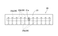
- FIG. 2 is a side view of the fluid nozzle as viewed from the front side.
- FIG. 2 is an exploded perspective view showing a fluid nozzle.
- 13 is a rear perspective view showing the fluid nozzle with the rear plate removed.
- FIG. FIG. 6 is an enlarged view showing a portion VI in FIG. 5 .
- FIG. 7 is a cross-sectional view taken along line VII-VII of FIG. 3 . 5 is an explanatory diagram for explaining a flow path of a coolant inside the fluid nozzle.
- FIG. FIG. 8 is a view corresponding to FIG. 7 and shows a comparative example.
- FIG. 11 is a schematic side view of a fluid nozzle as viewed from the front side, showing an example of another embodiment.
- FIG. 10 is a view showing
- FIGS. 1 and 2 show a machine tool 1 equipped with a fluid nozzle 20 of the embodiment.
- This machine tool 1 is a horizontal machining center and includes a bed 2, a column 3, a spindle head 5, a spindle 6, a table 7, and a protective cover 9, and the fluid nozzle 20 ejects coolant along the protective cover 9 of the machine tool 1 as described below (see the two-dot chain lines in FIGS. 1 and 2). Note that in FIGS. 1 and 2, which show the entire machine tool 1, only the main components in this embodiment are shown.
- the bed 2 is composed of a linear first bed 2a and a linear second bed 2b connected perpendicularly to the first bed 2a, and has an overall T-shape in a plan view.
- the table 7 is disposed on the second bed 2b and is guided by a guide rail 8 to move forward and backward relative to the first bed 2a, i.e., in the horizontal direction of the arrow Z.
- the column 3 is disposed on the first bed 2a (see FIG. 2) and is guided by guide rails 4 so as to move in the direction of the X-axis (the direction perpendicular to the plane of the paper in FIG. 2) which is horizontally perpendicular to the Z-axis.
- the spindle head 5 rotatably supports the spindle 6 and is held by the column 3 so as to be movable in the vertical Y-axis direction which is perpendicular to the X-axis and Z-axis.
- the spindle head 5 moves within the X-axis-Y-axis plane.
- the protective cover 9 is composed of multiple cover bodies 9a (see Figure 1) connected by a pantograph mechanism (not shown) provided on the back side of the cover bodies.
- the protective cover 9 is attached to a frame-shaped sheet metal frame 15 erected on the first bed 2a, and is positioned so as to separate the base end side of the column 3 and spindle head 5 from the machining area (the area above the second bed 2b).
- the fluid nozzle 20 is arranged on the front side of the upper end of the sheet metal frame 15 with a small gap therebetween, and extends in the X-axis direction as viewed from the front side of the machine tool 1.
- the fluid nozzle 20 is inclined at approximately 45° with respect to the vertical direction (Y-axis direction) so that the lower end edge is located rearward of the upper end edge as viewed from the X-axis direction.
- the fluid nozzle 20 is fixed to the sheet metal frame 15 with bolts via L-shaped brackets (not shown) provided at both ends in the longitudinal direction.
- the fluid nozzle 20 then flows the coolant supplied from the coolant supply device 10 (see FIG. 2) installed on the rear side of the machine tool 1 downward along the front side of the protective cover 9.
- the coolant that reaches the lower end of the protective cover 9 flows downward from the upper surface of the second bed 2b, and then returns to the coolant tank 11 of the coolant supply device 10 through the return pipe 13.
- the coolant supply device 10 filters the returned coolant, and supplies the filtered coolant again to the fluid nozzle 20 from the supply pipe 14 by the power of the coolant pump 12. In this way, the coolant flows along a series of circulation paths (see the arrows in FIG. 2) that pass through the coolant supply device 10 and the fluid nozzle 20.
- the fluid nozzle 20 has a flat rectangular shape in an overall view and is disposed vertically so that its thickness direction faces the horizontal direction (Z-axis direction in this example).
- a coolant supply hole 21a (corresponding to a fluid supply hole) is formed on the front side surface of the fluid nozzle 20.
- the fluid nozzle 20 is disposed with the coolant supply hole 21a facing the back side of the machine tool 1 (see Fig. 1).
- the fluid nozzle 20 is configured to branch the coolant supplied from the coolant supply hole 21a into multiple branches and then discharge them from the lower end surface of the nozzle.
- the fluid nozzle 20 is constructed by stacking four plate materials 21 to 24 in the plate thickness direction.
- Each plate material 21 to 24 has a rectangular shape when viewed in the plate thickness direction and is made of a metal material such as aluminum, and each plate material is bonded to each other with an adhesive. Note that it is not necessary to use an adhesive to bond each plate material to each other, and it may be possible to use only bolt fastening, for example.
- the four plate materials 21 to 24 consist of a front plate material 21, a rear plate material 22 arranged on the rear side of the front plate material 21, and a first intermediate plate material 23 and a second intermediate plate material 24 arranged between the front plate material 21 and the rear plate material 22.
- the first intermediate plate material 23 and the second intermediate plate material 24 are arranged in this order from the front side to the rear side of the fluid nozzle 20.
- the front plate material 21 has the coolant supply hole 21a in the center in the longitudinal direction.
- the coolant supply hole 21a is a circular hole into which the screw-in type pipe joint 25 is screwed.
- the supply pipe 14 is connected to the pipe joint 25, and the coolant from the coolant supply device 10 is supplied to the coolant supply hole 21a via this supply pipe 14.
- the first and second intermediate plate members 23, 24 are formed with a fluid passage 26 through which the coolant supplied from the coolant supply hole 21a flows.
- This fluid passage 26 is composed of an inlet opening 23a and multiple inlet cutouts 23b formed in the first intermediate plate 23, and multiple outlet cutouts 24a formed in the second intermediate plate 24.
- each discharge notch 24a is formed to extend in the vertical direction (the vertical direction of the second intermediate plate 24 in this example) and open to the bottom. More specifically, as shown in Fig. 6, each discharge notch 24a is composed of a slit-shaped straight portion 24b extending in the vertical direction and a flared portion 24c connected to the lower end of the straight portion 24b. The flared portion 24c is formed so that the flow path width (the dimension in the flow path width direction perpendicular to the plate thickness direction) becomes wider from the top to the bottom.
- the flared portion 24c is formed so that the flow path width becomes wider from the upstream side to the downstream side in the coolant discharge direction.
- the flow path width at the upper end position of the flared portion 24c is equal to the flow path width of the straight portion 24b.
- the divergence angle ⁇ of the divergent portion 24c as viewed in the plate thickness direction is set to, for example, 120° or more and 150° or less.
- the introduction opening 23a is a rectangular opening formed over the entire longitudinal direction of the first intermediate plate 23.
- the introduction opening 23a is formed across the multiple discharge notches 24a.
- the introduction opening 23a is formed so that its upper edge is located slightly above the upper end position of the straight portion 24b of the discharge notch 24a, and its lower edge is located above the lower end position of the straight portion 24b.
- the introduction opening 23a is formed so as to overlap a part of the upper end side of the straight portion 24b of each discharge notch 24a (in this example, a range of approximately 2/3 of the upper end side of the straight portion 24b).
- each introduction notch 23b is formed in a U-shape (an example of a concave shape) that opens toward the introduction opening 23a (upper side in this example).
- each introduction notch 23b is formed so as to overlap with a part of each discharge notch 24a formed in the second intermediate plate material 24 when viewed from the plate thickness direction. More specifically, each introduction notch 23b is formed so as to overlap with the lower end of the straight portion 24b in each discharge notch 24a when viewed from the plate thickness direction.
- each introduction notch 23b in the width direction coincides with both ends of each discharge notch 24a in the width direction when viewed from the plate thickness direction.
- the lower end position of each introduction notch 23b coincides with the upper end position of the flared portion 24c in each discharge notch 24a.
- FIG. 8 is an explanatory diagram for explaining the coolant flow path in the fluid nozzle 20.
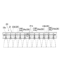
- the coolant supplied to the coolant supply hole 21a from the front side of the fluid nozzle 20 spreads to both sides in the left and right direction of FIG. 8 so as to fill the space inside the introduction opening 23a formed in the first intermediate plate material 23.
- This spread coolant flows from the introduction opening 23a into each discharge notch 24a, and is then discharged in a film form from the flared portion 24c at the lower end of each discharge notch 24a (see the two-dot chain line in FIG. 8).
- the reason why this reduction in piping is possible will be explained based on a comparison with a comparative fluid nozzle 120 shown in Figure 9.
- the comparative fluid nozzle 120 differs from this embodiment in that it does not have multiple introduction notches 23b, but the rest of the configuration is the same as this embodiment.
- the same components as in the embodiment are indicated by the reference numerals used in the embodiment with 100 added.
- the introduction notch 23b formed in the first intermediate plate 23 communicates with the straight portion 24b of each discharge notch 24a, thereby ensuring a flow passage thickness ta equivalent to two plate thicknesses.
- the flow passage thickness is sufficiently ensured when the coolant flows from the introduction opening 23a into the lower flow passage portion 24d of the discharge notch 24a, thereby reducing the pipeline resistance. This prevents the amount of coolant flowing into the lower flow passage portion 24d of the discharge notch 24a from becoming insufficient, and in turn ensures that the coolant can be discharged from the lower end of each discharge notch 24a at the desired flow rate and shape.
- each discharge notch 24a is a diverging portion 24c whose dimension in the flow path width direction increases from the upstream side to the downstream side in the fluid discharge direction (from the top to the bottom in Figure 6).
- each discharge notch 24a spreads in the flow path width direction along the inner wall surface of the flared portion 24c and is discharged in the form of a film. Therefore, the coolant discharge range can be expanded over a wider area than when the coolant is discharged in a line from each discharge notch 24a (see FIG. 8). This in turn increases the cleaning effect of the protective cover 9 by the coolant as much as possible.
- each inlet notch 23b is located at the same height as the upper end of the flared portion 24c of each outlet notch 24a (see Figures 6 and 7).
- the coolant introduced into each introduction notch 23b through the introduction opening 23a can be supplied to the portion of each discharge notch 24a above the flared portion 24c. Therefore, the coolant can be smoothly spread over the entire area from the upper end to the lower end of the flared portion 24c without peeling. This ensures that the coolant can be spread over the flared portion 24c.
- each discharge notch 24a to the flared portion 24c is a straight section 24b consisting of a straight slit hole.
- the outer edge shape of the fluid nozzle 20 is rectangular, but this is not limited thereto and may be any shape, such as circular or triangular.
- Fig. 10 shows an embodiment in which both ends of the lower edge of the fluid nozzle 20 are chamfered to form a non-rectangular shape. Note that in Fig. 10 and Fig. 11 described later, the same components as those in the above embodiment are denoted by the same reference numerals.
- the fluid nozzle 20 is inclined at approximately 45° with respect to the vertical direction (Y-axis direction) so that the lower edge is located behind the upper edge when viewed from the X-axis direction, but this is not limited to this. That is, the inclination angle of the fluid nozzle 20 may be greater than 45° or less than 45°.
- the fluid nozzle 20 may also be arranged horizontally or vertically without being inclined when viewed from the X-axis direction. Also, for example, when supplying coolant to the surface of the workpiece W located in the processing area, the fluid nozzle 20 may be inclined so that its lower edge is located forward of its upper edge.
- each introduction notch 23b formed in the first intermediate plate 23 is formed in a U-shape that opens toward the introduction opening 23a, but this is not limited thereto and may be formed, for example, in a semicircular or triangular shape.
- each of the inlet notches 23b formed in the first intermediate plate 23 is formed so as to overlap a portion of each of the discharge notches 24a that is located below the inlet opening 23a when viewed from the plate thickness direction, but this is not limited thereto, and for example, as shown in FIG. 11, each of the discharge notches 24a may be formed so as to overlap a portion of each of the discharge notches 24a that is located above the inlet opening 23a.
- each of the inlet notches 23b may have any configuration as long as it is formed so as to overlap a portion of each of the discharge notches 24a when viewed from the plate thickness direction.
- the discharge notches 24a are formed at intervals from one another along one edge side (lower edge side) of the second intermediate plate 24, but this is not limited thereto, and for example, the discharge notches 24a may be formed at intervals from one another along the entire edge of the second intermediate plate 24. This makes it possible to discharge fluid from the entire peripheral side surface of the fluid nozzle 20, thereby expanding the range of uses of the fluid nozzle 20 in various ways.
- the lower end position of the introduction notch 23b is at the same height as the upper end position of the flared portion 24c, but this is not limited thereto, and it may be located above the upper end position of the flared portion 24c. This allows the coolant to be smoothly spread without peeling over the entire area from the upper end to the lower end of the flared portion 24c, just like in the above embodiment.
- coolant was described as an example of the fluid ejected from the fluid nozzle 20, but this is not limited thereto, and the fluid may be other liquids such as water, or may be a gas such as air.
- the fluid nozzle 20 was placed near the upper end of the sheet metal frame 15 of the machine tool 1, but this is not limited to this, and for example, the fluid nozzle 20 may be placed in a shutter opening/closing section of a tool changer provided on the machine tool 1. Furthermore, the fluid nozzle 20 can be used for a variety of purposes, such as blocking dust with a fluid and diffusing gas in an air purifier or air conditioner, rather than being limited to cleaning chips and the like.
- Fluid passage 21 Front plate material 21a Coolant supply hole (fluid supply hole) 22 Back plate 23 First intermediate plate 23a Introduction opening (fluid passage) 23b Introduction notch (fluid passage) 24 Second intermediate plate 24a Discharge notch portion (fluid passage) 24b Straight portion 24c Expanded portion 26 Fluid passage
Landscapes
- Engineering & Computer Science (AREA)
- Mechanical Engineering (AREA)
- Nozzles (AREA)
Priority Applications (3)
| Application Number | Priority Date | Filing Date | Title |
|---|---|---|---|
| JP2024562468A JP7854069B2 (ja) | 2022-12-07 | 2022-12-07 | 流体ノズル |
| EP22967817.2A EP4613424A1 (en) | 2022-12-07 | 2022-12-07 | Fluid nozzle |
| PCT/JP2022/045075 WO2024121966A1 (ja) | 2022-12-07 | 2022-12-07 | 流体ノズル |
Applications Claiming Priority (1)
| Application Number | Priority Date | Filing Date | Title |
|---|---|---|---|
| PCT/JP2022/045075 WO2024121966A1 (ja) | 2022-12-07 | 2022-12-07 | 流体ノズル |
Publications (1)
| Publication Number | Publication Date |
|---|---|
| WO2024121966A1 true WO2024121966A1 (ja) | 2024-06-13 |
Family
ID=91378949
Family Applications (1)
| Application Number | Title | Priority Date | Filing Date |
|---|---|---|---|
| PCT/JP2022/045075 Ceased WO2024121966A1 (ja) | 2022-12-07 | 2022-12-07 | 流体ノズル |
Country Status (3)
| Country | Link |
|---|---|
| EP (1) | EP4613424A1 (https=) |
| JP (1) | JP7854069B2 (https=) |
| WO (1) | WO2024121966A1 (https=) |
Citations (6)
| Publication number | Priority date | Publication date | Assignee | Title |
|---|---|---|---|---|
| JPS56102657U (https=) * | 1980-01-08 | 1981-08-12 | ||
| JPH10156660A (ja) | 1996-11-29 | 1998-06-16 | Nippei Toyama Corp | 工作機械のクーラント供給装置 |
| JP2000334333A (ja) * | 1999-05-31 | 2000-12-05 | Daiko Kennetsu Kk | 流体の整流機構 |
| JP2006281767A (ja) * | 2005-03-09 | 2006-10-19 | Ricoh Co Ltd | 液体吐出ヘッド及びその製造方法、画像形成装置、液滴を吐出する装置、記録方法 |
| JP2008080464A (ja) * | 2006-09-28 | 2008-04-10 | Masayoshi Watabe | 液体カーテン生成装置及びその生成方法 |
| JP2021061389A (ja) * | 2019-10-04 | 2021-04-15 | 株式会社荏原製作所 | ノズル及び基板洗浄装置 |
-
2022
- 2022-12-07 JP JP2024562468A patent/JP7854069B2/ja active Active
- 2022-12-07 WO PCT/JP2022/045075 patent/WO2024121966A1/ja not_active Ceased
- 2022-12-07 EP EP22967817.2A patent/EP4613424A1/en active Pending
Patent Citations (6)
| Publication number | Priority date | Publication date | Assignee | Title |
|---|---|---|---|---|
| JPS56102657U (https=) * | 1980-01-08 | 1981-08-12 | ||
| JPH10156660A (ja) | 1996-11-29 | 1998-06-16 | Nippei Toyama Corp | 工作機械のクーラント供給装置 |
| JP2000334333A (ja) * | 1999-05-31 | 2000-12-05 | Daiko Kennetsu Kk | 流体の整流機構 |
| JP2006281767A (ja) * | 2005-03-09 | 2006-10-19 | Ricoh Co Ltd | 液体吐出ヘッド及びその製造方法、画像形成装置、液滴を吐出する装置、記録方法 |
| JP2008080464A (ja) * | 2006-09-28 | 2008-04-10 | Masayoshi Watabe | 液体カーテン生成装置及びその生成方法 |
| JP2021061389A (ja) * | 2019-10-04 | 2021-04-15 | 株式会社荏原製作所 | ノズル及び基板洗浄装置 |
Also Published As
| Publication number | Publication date |
|---|---|
| JP7854069B2 (ja) | 2026-04-30 |
| EP4613424A1 (en) | 2025-09-10 |
| JPWO2024121966A1 (https=) | 2024-06-13 |
Similar Documents
| Publication | Publication Date | Title |
|---|---|---|
| JP5877806B2 (ja) | 切粉の排出に適したカバーを備えた工作機械 | |
| US20230371200A1 (en) | Cooling Apparatus for Power Module | |
| US20230098828A1 (en) | Manufacturing device with large-area sinking gas stream | |
| US11161212B2 (en) | Laser machine for machining workpieces | |
| CN104380022B (zh) | 板式热交换器 | |
| US9358668B2 (en) | Fluid jet receiving receptacles and related fluid jet cutting systems | |
| JP7854069B2 (ja) | 流体ノズル | |
| JP2017508633A (ja) | ガラス処理装置およびガラス処理方法 | |
| KR102739205B1 (ko) | 배기유체 충돌식 소음기 | |
| JP5203795B2 (ja) | 棒状部材に対するガスメタルエンクローズ溶接装置 | |
| CN108290175B (zh) | 涂装车间以及整流装置 | |
| JP2011148188A (ja) | 溶融樹脂整流用ユニット | |
| KR101203458B1 (ko) | 처리 액체로 처리 대상을 처리하는 노즐 장치 및 방법 | |
| US20210037681A1 (en) | Plate cooler for aircraft electronic components | |
| CN118905423B (zh) | 一种激光切割机的水冷床身 | |
| JP4854687B2 (ja) | 冷却装置 | |
| JP6938421B2 (ja) | 流体流路装置 | |
| US20230203972A1 (en) | All-direction flow-through flow directing member with angled baffles | |
| JPS5997823A (ja) | 工作機械ベツドの熱変形防止装置 | |
| JP2005029146A (ja) | 建設機械 | |
| JP5775381B2 (ja) | ワイヤソーの加工液ノズル | |
| JP2024111785A (ja) | 肉盛加工ノズル | |
| KR102532744B1 (ko) | 공기순환 및 흡음이 용이한 부스 | |
| JP7647734B2 (ja) | ブレード | |
| JP4352933B2 (ja) | 建設機械のエンジン吸気装置 |
Legal Events
| Date | Code | Title | Description |
|---|---|---|---|
| 121 | Ep: the epo has been informed by wipo that ep was designated in this application |
Ref document number: 22967817 Country of ref document: EP Kind code of ref document: A1 |
|
| WWE | Wipo information: entry into national phase |
Ref document number: 2024562468 Country of ref document: JP |
|
| WWE | Wipo information: entry into national phase |
Ref document number: 2022967817 Country of ref document: EP |
|
| ENP | Entry into the national phase |
Ref document number: 2022967817 Country of ref document: EP Effective date: 20250606 |
|
| NENP | Non-entry into the national phase |
Ref country code: DE |
|
| WWP | Wipo information: published in national office |
Ref document number: 2022967817 Country of ref document: EP |