WO2024111326A1 - 距離測定装置 - Google Patents
距離測定装置 Download PDFInfo
- Publication number
- WO2024111326A1 WO2024111326A1 PCT/JP2023/038402 JP2023038402W WO2024111326A1 WO 2024111326 A1 WO2024111326 A1 WO 2024111326A1 JP 2023038402 W JP2023038402 W JP 2023038402W WO 2024111326 A1 WO2024111326 A1 WO 2024111326A1
- Authority
- WO
- WIPO (PCT)
- Prior art keywords
- light
- distance
- unit
- pixel block
- filter
- Prior art date
- Legal status (The legal status is an assumption and is not a legal conclusion. Google has not performed a legal analysis and makes no representation as to the accuracy of the status listed.)
- Ceased
Links
Images







Classifications
-
- G—PHYSICS
- G01—MEASURING; TESTING
- G01C—MEASURING DISTANCES, LEVELS OR BEARINGS; SURVEYING; NAVIGATION; GYROSCOPIC INSTRUMENTS; PHOTOGRAMMETRY OR VIDEOGRAMMETRY
- G01C3/00—Measuring distances in line of sight; Optical rangefinders
- G01C3/02—Details
- G01C3/06—Use of electric means to obtain final indication
Definitions
- This disclosure relates to a distance measuring device.
- parallax is detected from images captured by a pair of cameras.
- a pixel block that is most highly correlated with a target pixel block in an image captured by one camera (base image) is searched for in an image captured by the other camera (reference image).
- the search range is set in the direction in which the cameras are separated, with the same position as the target pixel block as the base position.
- the amount of pixel shift of the pixel block extracted by the search relative to the base position is detected as parallax. From this parallax, the distance to the object is calculated using triangulation.
- the mapping method for three-dimensional (3D) optical distance measurement in Patent Document 1 splits a light beam into multiple spots, forms spots with shape characteristics that change in a predetermined manner depending on the distance along the optical axis of the light beam, and projects a pattern of spots onto an object.
- the positions of the spots within the pattern are uncorrelated.
- the three-dimensional measurement system of Patent Document 2 has a first imaging unit and a second imaging unit that are spaced apart from each other.
- the image of the object captured by the first imaging unit and the second imaging unit is used, and the parallax of a first feature point in the image of the object is calculated by image processing based on a pattern projection method.
- the three-dimensional measurement system of Patent Document 2 uses both the images of the object captured by the first imaging unit and the second imaging unit, searches for a corresponding point to a second feature point in the image of the object by image processing based on a stereo camera method, calculates the parallax of the second feature point based on the search result, and identifies the three-dimensional shape of the object from the parallax of the first feature point and the parallax of the second feature point.
- the present disclosure aims to provide a distance measuring device that can reduce the time required for distance measurement while increasing resolution.
- a distance measuring device includes a first imaging unit and a second imaging unit arranged side by side to form an area where their fields of view overlap, a light projection unit that projects a pattern light in which a plurality of light regions having different wavelength bands are distributed in a predetermined pattern into the area where the fields of view overlap, and a measurement unit that measures the distance to an object surface onto which the predetermined pattern light is projected based on images captured by the first imaging unit and the second imaging unit, respectively.
- the light projection unit includes a light source including the wavelength band, a filter in which a plurality of filter regions for forming each of the plurality of light regions are distributed in a pattern similar to the predetermined pattern of the light regions, and a plurality of optical elements arranged on at least one of the entrance surface side and exit surface side of the filter region.
- the optical elements have a focal point and form the light regions.
- the distance measuring device disclosed herein can reduce the time required for distance measurement while increasing resolution.
- FIG. 1 is a diagram showing a basic configuration of a distance measuring device according to an embodiment.
- FIG. 1 is a diagram showing the configuration of a distance measuring device according to an embodiment.
- 5A to 5C are diagrams illustrating a method of setting pixel blocks for the entire first image according to the embodiment.
- 1A to 1C are diagrams each showing a schematic enlarged view of a part of the first image, illustrating a method of setting pixel blocks for the first image according to an embodiment;
- 1A and 1B are diagrams illustrating a configuration of a filter according to an embodiment of the present invention.
- 4B is an enlarged view of a portion of the configuration of the filter according to the embodiment of the present invention shown in FIG. 4A.
- FIG. 2 is a perspective view of a filter according to an embodiment.
- FIG. 2 is a perspective view of the filter according to the embodiment when microlenses are omitted.
- 5A and 5B are schematic diagrams illustrating an example of measuring the height of an object according to the embodiment.
- 1 is a schematic diagram showing an example of a pattern light according to an embodiment, in which the height of an object is h1.
- FIG. 10 is a schematic diagram showing an example of a pattern light according to the embodiment, in which the height of an object is h2.
- FIG. 10 is a schematic diagram showing an example of pattern light according to the embodiment, in which the height of an object is h3.
- FIG. FIG. 13 is a schematic diagram showing an example of pattern light according to the embodiment, in which the height of an object is h4.
- FIG. 4 is a graph showing the spectral output of a light source to explain a wavelength band output by the light source according to the embodiment.
- 5 is a graph showing the spectral transmittance of a filter region for explaining a wavelength band output by a light source according to the embodiment.
- 6 is a flowchart for explaining a method for calculating a distance index value of a measurement unit according to an embodiment.
- 10 is a diagram showing an example of luminance values in a first pixel block according to the embodiment, in which the height of an object is h1.
- FIG. 13 is a diagram showing an example of luminance values in a first pixel block according to the embodiment, in which the height of an object is h2.
- FIG. 13 is a diagram showing an example of luminance values in a first pixel block according to the embodiment, where the height of an object is h3.
- FIG. 13 is a diagram showing an example of luminance values in a first pixel block according to the embodiment, where the height of an object is h4.
- 13 is a diagram showing an example of luminance values in a second pixel block according to the embodiment, in which the height of an object is h1.
- FIG. 13 is a diagram showing an example of luminance values in a second pixel block according to the embodiment, in which the height of an object is h2.
- FIG. 13 is a diagram showing an example of luminance values in a second pixel block according to the embodiment, in which the height of an object is h3.
- FIG. 13 is a diagram showing an example of luminance values in a second pixel block according to the embodiment, in which the height of an object is h3.
- FIG. 13 is a diagram showing an example of luminance values in a second pixel block according to the embodiment, in which the height of an object is h4.
- FIG. 11 is a graph showing a relationship between a distance index value and an actual height of an object according to the embodiment.
- 1A and 1B are diagrams illustrating a state in which a target pixel block is set on a first image, for explaining a method of searching for a target pixel block according to an embodiment
- 13B is a diagram illustrating a search range set on the second image for searching for the target pixel block of FIG. 13A, for explaining a method for searching for a target pixel block according to an embodiment
- FIG. FIG. 13 is a diagram showing a configuration of a distance measuring device according to a modified example.
- FIG. 13 is a diagram showing the spectral output of a light source to explain a wavelength band output by a light source according to a modified example.
- FIG. 13 is a diagram showing the spectral transmittance of a filter region for explaining a wavelength band output by a light source according to a modified example.
- FIG. 13 is a perspective view of a filter according to a modified example.
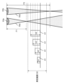
- FIG. 1 is a diagram showing a basic configuration of a distance measuring device 1 according to an embodiment.
- the distance measurement device 1 includes a first imaging unit 10, a second imaging unit 20, and a light projecting unit 30.
- the first imaging unit 10 images a range of a field of view 10a facing the positive direction of the Z axis.
- the second imaging unit 20 images a range of a field of view 20a facing the positive direction of the Z axis.
- the first imaging unit 10 and the second imaging unit 20 are arranged side by side at a predetermined distance (baseline length) in the X-axis direction so that the fields of view 10a, 20a overlap each other.
- the imaging direction of the first imaging unit 10 may be slightly tilted from the positive direction of the Z axis toward the second imaging unit 20, and the imaging direction of the second imaging unit 20 may be slightly tilted from the positive direction of the Z axis toward the first imaging unit 10.
- imaging direction refers to the direction of the optical axis of the first imaging unit 10 or the direction of the optical axis of the second imaging unit 20.
- the light projecting unit 30 projects pattern light 30a, in which light is distributed in a predetermined pattern, in the area where the visual fields 10a and 20a overlap.
- the direction in which the light projecting unit 30 projects the pattern light 30a is the positive direction of the Z axis.
- the pattern light 30a is projected onto the surface of an object A1 that exists in the area where the visual fields 10a and 20a overlap.
- the distance measurement device 1 measures the distance D0 to the object A1 by stereo corresponding point search using the images captured by the first imaging unit 10 and the second imaging unit 20, respectively.
- pattern light 30a is projected from the light projector 30 onto the surface of the object A1.
- the pattern of the pattern light 30a is projected onto the images captured by the first imaging unit 10 and the second imaging unit 20. Therefore, even if the surface of the object A1 is plain, stereo corresponding point search can be performed with high accuracy, and the distance D0 to the surface of the object A1 can be accurately measured.
- FIG. 2 is a diagram showing the configuration of a distance measuring device according to an embodiment.
- the first imaging unit 10 includes an imaging lens 11 and an imaging element 12.
- the imaging lens 11 has a focal length and focuses light from the field of view 10a onto the imaging surface 12a of the imaging element 12.
- the imaging lens 11 does not have to be a single lens, and may be configured by combining multiple lenses.
- the imaging element 12 is a color image sensor.
- the imaging element 12 is, for example, a CMOS (Complementary Metal Oxide Semiconductor) image sensor. Note that the imaging element 12 may also be a CCD (Charge Coupled Device).
- the second imaging section 20 has the same configuration as the first imaging section 10.
- the second imaging section 20 includes an imaging lens 21 and an imaging element 22.
- the imaging lens 21 has the same focal length as the imaging lens 11, and focuses light from the field of view 20a onto the imaging surface 22a of the imaging element 22.
- the imaging lens 21 does not have to be a single lens, and may be configured by combining multiple lenses.
- the imaging element 22 is a color image sensor. Note that the imaging element 22 is, for example, a CMOS image sensor.
- the imaging element 22 may also be a CCD.
- the light projection unit 30 includes light sources 31 to 33, an optical system 34, a filter 35, and a projection lens 36.
- Light sources 31 to 33 emit light in different wavelength bands. For example, light source 31 emits light in a wavelength band near red, light source 32 emits light in a wavelength band near green, and light source 33 emits light in a wavelength band near blue. Light sources 31 to 33 are, for example, light-emitting diodes. Note that light sources 31 to 33 may also be other types of light sources, such as semiconductor lasers.
- the optical system 34 includes collimator lenses 341-343 and dichroic mirrors 344 and 345.
- the collimator lenses 341-343 convert the light emitted from the light sources 31-33 into approximately parallel light, respectively.
- the dichroic mirror 344 transmits the light incident from the collimator lens 341 and reflects the light incident from the collimator lens 342.
- the dichroic mirror 345 transmits the light incident from the dichroic mirror 344 and reflects the light incident from the collimator lens 343. In this way, the light emitted from the light sources 31-33 is combined and guided to the filter 35.
- the filter 35 generates pattern light 30a in which multiple types of light regions having different wavelength bands are distributed in a predetermined pattern from the light of each wavelength band guided from the optical system 34.
- the specific configuration of the filter 35 will be described later.
- the projection lens 36 projects the pattern light 30a generated by the filter 35.
- the projection lens 36 does not have to be a single lens, and may be configured by combining multiple lenses.
- the distance measurement device 1 includes, as its circuit configuration, a first image capture processing unit 41, a second image capture processing unit 42, a light source driving unit 43, a brightness adjustment unit 44, a measurement unit 45, a control unit 46, and a communication interface 47.
- the first imaging processing unit 41 and the second imaging processing unit 42 control the imaging elements 12 and 22, and perform processes such as brightness correction and camera calibration on the pixel signals of the first image and the second image output from the imaging elements 12 and 22, respectively.
- the light source driving unit 43 drives each of the light sources 31 to 33 with the driving current value set by the brightness adjustment unit 44.
- the brightness adjustment unit 44 sets the drive current values of the light sources 31 to 33 in the light source drive unit 43 based on the pixel signals (brightness) of the second image input from the second imaging processing unit 42. Specifically, the brightness adjustment unit 44 sets the drive current values (light emission amount) of the light sources 31 to 33 so that the maximum brightness based on the light from the light sources 31 to 33 acquired based on the pixel signals from the second imaging unit 20 does not become saturated.
- the measurement unit 45 performs a stereo correspondence search by comparing the first image and the second image input from the first imaging processing unit 41 and the second imaging processing unit 42, respectively, and obtains the distance to the surface of the object A1 for each pixel block on the first image.
- the measurement unit 45 transmits the obtained distance information for all pixel blocks to an external device via the communication interface 47.
- the measurement unit 45 sets a pixel block for which distance is to be obtained (hereinafter referred to as the "target pixel block”) on the first image, and searches for a pixel block corresponding to this target pixel block, i.e., a pixel block that is most suitable for the target pixel block (hereinafter referred to as the "suitable pixel block”), within a search range defined on the second image.
- the target pixel block a pixel block for which distance is to be obtained
- the measurement unit 45 then obtains the pixel shift amount between a pixel block (hereinafter referred to as the "reference pixel block") that is located in the same position as the target pixel block on the second image and the suitable pixel block extracted from the second image by the above search, and performs processing to calculate the distance to the surface of the object A1 at the position of the target pixel block from the obtained pixel shift amount.
- the reference pixel block a pixel block
- the measurement unit 45 and the communication interface 47 may be configured with a semiconductor integrated circuit consisting of an FPGA (Field Programmable Gate Array). Furthermore, each of these units may be configured with other semiconductor integrated circuits such as a DSP (Digital Signal Processor), a GPU (Graphics Processing Unit) and an ASIC (Application Specific Integrated Circuit).
- FPGA Field Programmable Gate Array
- DSP Digital Signal Processor
- GPU Graphics Processing Unit
- ASIC Application Specific Integrated Circuit
- the control unit 46 is configured with a microcomputer or the like, and controls each part according to a specific program stored in the built-in memory.
- FIGS. 3A and 3B are diagrams that show a schematic diagram of a method for setting pixel blocks for the first image. Specifically, FIG. 3A shows a method for setting pixel blocks 102 for the entire first image 100, and FIG. 3B shows an enlarged view of a portion of the first image 100.
- the first image 100 is divided into a number of pixel blocks 102, each of which includes a predetermined number of pixel regions 101.
- the pixel region 101 is an area that corresponds to one pixel on the image sensor 12. In other words, the pixel region 101 is the smallest unit of the first image 100.
- one pixel block 102 is made up of nine pixel regions 101 arranged in three rows and three columns. However, the number of pixel regions 101 included in one pixel block 102 is not limited to this.
- FIGS. 4A and 4B are diagrams showing the configuration of a filter according to an embodiment. Specifically, FIG. 4A is a diagram showing a schematic configuration of filter 35. FIG. 4B is a diagram showing an enlarged view of a portion of FIG. 4A. FIG. 4A and FIG. 4B show filter 35 as viewed from the light incident surface 35a side.
- filter 35 has multiple types of filter regions 351-354 formed in a predetermined pattern.
- the types of filter regions 351-354 are indicated by different types of hatching.
- Filter regions 351-354 selectively transmit light of different wavelength bands and form light regions of different hues.
- filter region 351 forms a light region corresponding to the hue "red”
- filter region 352 forms a light region corresponding to the hue "orange”
- filter region 353 forms a light region corresponding to the hue "green”
- filter region 354 forms a light region corresponding to the hue "blue.”
- the characteristics of light sources 31-33 and filter regions 351-354 will be described later.
- each of the filter regions 351 to 354 is set to a size that corresponds approximately to one pixel block on the image sensor 12, 22, for example.
- the region B1 shown by the dashed line in FIG. 4B corresponds to the region of a pixel block (pixel block 102 used in the above-mentioned stereo correspondence search) consisting of three pixels vertically and three pixels horizontally on the image sensor 12, 22. That is, when the distance D0 to the surface of the object A1 is a reference distance (for example, the intermediate distance of the ranging range), the light of this region B1 is projected onto the region of a pixel block consisting of three pixels vertically and three pixels horizontally on the image sensor 12, 22.
- each of the filter regions 351 to 354 is not necessarily limited to a size corresponding to one pixel.
- the size of each of the filter regions 351 to 354 may be larger or smaller than the size corresponding to one pixel block.
- each of the filter regions 351 to 354 is rectangular and has the same size, but each of the filter regions 351 to 354 may have a different size, or may have another shape, such as a square or a circle.
- the filter regions 351 to 354 are arranged so that different types of filter regions are included in the region B1 corresponding to all pixel blocks used in the stereo correspondence search, and it is even more preferable that the filter regions 351 to 354 are arranged so that all types of filter regions are included in each of these regions B1. Furthermore, it is preferable that the arrangement pattern of the filter regions included in the region B1 corresponding to the pixel blocks is unique (random) for each pixel block at each search position, at least in the search range R0 (see FIG. 13B described later) in the stereo correspondence search.
- filter regions 351-354 are arranged in this manner, as described below, the luminance of the light that passes through filter regions 351-354 can be made different from one another, so that the luminance distribution of light within each pixel block can be made unique for each pixel block. This can improve the accuracy of the stereo correspondence point search, and as a result, the accuracy of distance measurement can be improved.
- FIG. 5A and 5B are perspective views of a filter according to an embodiment. Specifically, FIG. 5A shows a perspective view of filter 35, and FIG. 5B shows a perspective view of filter 35 when microlens 53 is omitted.
- the filter 35 includes a transparent substrate 51, a filter layer 52, and a number of microlenses 53 (optical elements).
- the transparent substrate 51 is disposed on the incident surface 35a side of the filter layer 52, and transmits the light incident from the light sources 31 to 33.
- the transparent substrate 51 is, for example, a transparent glass substrate.
- Filter layer 52 has multiple types of filter regions, including filter regions 351 to 354, formed in a predetermined pattern. As shown in FIG. 5B, each filter region formed in filter layer 52 is formed in a rectangular shape in a plan view.
- the multiple microlenses 53 are arranged on the exit surface side of the filter layer 52, receive light incident from the light sources 31 to 33 via the transparent substrate 51 and the filter layer 52, and project the pattern light 30a. Specifically, the multiple microlenses 53 are arranged in an array in the X and Y directions so as to correspond to the filter regions, respectively.
- the multiple microlenses 53 include multiple microlenses 53 with different focal lengths.
- the multiple microlenses 53 include at least a microlens 53a (first optical element) with a focal position F1 and a microlens 53b (second optical element) with a focal position F2.
- the focal position F1 (first focal point) is on the closer side of the distance measurement device 1 than the measurement range S0 of the distance measurement device 1
- the focal position F2 (second focal point) is on the farther side of the distance measurement device 1 than the measurement range S0 of the distance measurement device 1 (see FIG. 1 and FIG. 6 described below).
- the focal length of the microlens 53b is greater than the focal length of the microlens 53a.
- a microlens with a continuous optical surface has been used as one embodiment of the optical element, but the invention is not limited to this.
- a Fresnel lens with multiple ring zones or a diffractive lens can also be used.
- FIG. 6 is a schematic diagram showing an example of measuring the height of object A1 in an embodiment.
- the height h see FIG. 1
- the position of the surface of object A1 approaches the focal position F1 of microlens 53a (and conversely, moves away from the focal position F2 of microlens 53b).
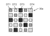
- FIGS. 7A to 7D are schematic diagrams showing examples of pattern light according to this embodiment corresponding to the four different height situations of object A1 shown in FIG. 6. Specifically, FIGS. 7A to 7D correspond to pattern light 30a when the height h (see FIG. 1) of object A1 is h1 to h4, respectively.
- each pattern light 30a includes an array of dot lights DT1 to DT4 consisting of multiple light regions.
- the multiple dot lights DT1 to DT4 each have a different hue.
- the dot light DT1 corresponds to a "green” hue
- the dot light DT2 corresponds to an "orange” hue
- the dot light DT3 corresponds to a "blue” hue
- the dot light DT4 corresponds to a "red” hue.
- the shape of each dot of light contained in the pattern light 30a changes depending on the height of the object A1 (measurement distance D0).
- FIGS. 8A and 8B are diagrams for explaining the wavelength band output by the light source according to the embodiment.
- FIG. 8A is a graph showing the spectral output of light sources 31 to 33.
- the spectral output of light sources 31, 32, and 33 is shown by a solid line E11, a dashed line E12, and a dotted line E13, respectively.
- the vertical axis of the graph is normalized by the maximum output of light source 31.
- Light source 31 emits light with a central wavelength of about 610 nm and an emission bandwidth of about 80 nm.
- Light source 32 emits light with a central wavelength of about 520 nm and an emission bandwidth of about 150 nm.
- Light source 33 emits light with a central wavelength of about 470 nm and an emission bandwidth of about 100 nm.
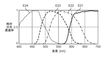
- FIG. 8B is a graph showing the spectral transmittance of filter regions 351 to 354.
- the spectral transmittance of filter regions 351, 352, 353, and 354 is shown by a solid line E21, a dashed line E22, a dashed line E23, and a dotted line E24, respectively.
- the vertical axis of the graph is normalized by the maximum transmittance of filter region 351.
- the filter region 351 has a transmittance that increases with an increase in wavelength from around 570 nm, and maintains a maximum transmittance at around 650 nm or more.
- the filter region 351 mainly transmits light from the light source 31, forming a light region (dot light) with a hue of "red”.
- the filter region 352 has a maximum transmittance of around 560 nm and a spectral characteristic with a transmission wavelength width of about 160 nm, mainly transmits light from the light source 31 and light from the light source 32, forming a light region (dot light) with a hue of "orange”.
- the filter region 353 has a maximum transmittance of around 520 nm and a spectral characteristic with a transmission bandwidth of about 150 nm, mainly transmits light from the light source 32, forming a light region (dot light) with a hue of "green”.
- the filter region 354 has a maximum transmittance of around 460 nm and a spectral characteristic with a transmission bandwidth of about 150 nm, mainly transmits light from the light source 33, and forms a light region (dot light) with a hue of "blue”.
- filters with four types of spectral transmittance it is possible to form light regions (dot lights) of even more different hues by adding filters with spectral transmittances that transmit multiple wavelength ranges from the wavelength ranges of light sources 31 to 33.
- the measurement unit 45 calculates the distance index value based on the first image and the second image.
- FIG. 9 is a flow chart for explaining a method for calculating a distance index value of the measurement unit 45 according to the embodiment.
- FIGS. 10A to 10D are schematic diagrams showing an example of luminance values in a first pixel block.
- FIGS. 11A to 11D are schematic diagrams showing an example of luminance values in a second pixel block.
- the first pixel block is a pixel block corresponding to a microlens 53a having a focal length F1 set on the closer side of the distance measurement device 1 than the measurement range S0 of the distance measurement device 1.
- the second pixel block is a pixel block corresponding to a microlens 53b having a focal length F2 set on the farther side of the distance measurement device 1 than the measurement range R0 of the distance measurement device 1.
- FIGS. 10A to 10D show luminance values when the heights of the object A1 are h1 to h4, respectively.
- FIGS. 11A to 11D show luminance values when the heights of the object A1 are
- the measurement unit 45 extracts the luminance value of each pixel contained in the first pixel block and the second pixel block (step S1). For example, if one pixel block is made up of nine pixel regions 101 arranged in three rows and three columns, the measurement unit 45 extracts the luminance value of each pixel that constitutes the first pixel block and the second pixel block (see Figures 10A to 10D and Figures 11A to 11D).
- the measurement unit 45 obtains the luminance center of gravity of the first pixel block and the second pixel block based on the extraction result in step S1 (step S2).
- the measurement unit 45 divides each of the first pixel block and the second pixel block into three regions with the luminance center of gravity of the first pixel block and the second pixel block as the center, and calculates the luminance value of each region (step S3).
- the first pixel block and the second pixel block are each divided into three in the left-right direction of the drawing with the luminance center of gravity as the center.
- the luminance of the pixels existing on the straight line dividing the first pixel block and the second pixel block is distributed to each region according to the area divided by the straight line. In this way, the luminance value of each region is calculated.
- the measurement unit 45 calculates the distance index value (step S4). Specifically, assuming that the luminance values of the central area, left area, and right area of the first pixel block are R1, R2, and R3, respectively (see FIG. 10A for specific examples), and the luminance values of the central area, left area, and right area of the second pixel block are G1, G2, and G3, respectively (see FIG. 11A for specific examples), the distance index value is expressed by the following formula (1).
- FIG. 12 is a graph showing the relationship between the distance index value and the actual height of an object according to the embodiment. As shown in FIG. 12, the distance index value is calculated to have a linear dependency on the actual height h of object A1 (distance D0 to object A1). This makes it easier to handle the distance index value.
- FIGS. 13A and 13B are diagrams for explaining a method for searching for a target pixel block according to an embodiment.
- FIG. 13A is a diagram that shows a schematic diagram of a state in which a target pixel block TB1 is set on a first image 100
- FIG. 13B is a diagram that shows a schematic diagram of a search range R0 that is set on a second image 200 to search for the target pixel block of FIG. 13A.
- the second image 200 acquired from the second imaging unit 20 is divided into a number of pixel blocks 202, similar to the first image 100.
- the pixel blocks 202 include the same number of pixel regions as the pixel blocks 102 described above.
- the target pixel block TB1 is the pixel block 102 to be processed among the pixel blocks 102 in the first image 100.
- the reference pixel block TB2 is the pixel block 202 in the second image 200 that corresponds to the target pixel block TB1.
- the measurement unit 45 identifies a reference pixel block TB2 that corresponds to the target pixel block TB1 on the second image 200. The measurement unit 45 then sets the position of the identified reference pixel block TB2 as a reference position P0 of the search range R0, and sets the range extending from this reference position P0 in the direction in which the first imaging unit 10 and the second imaging unit 20 are separated as the search range R0.
- the measurement unit 45 identifies the reference pixel block TB2 corresponding to the target pixel block TB1 in the first image based on the distance index value calculated in step S4 of FIG. 9. For example, the measurement unit 45 sets the pixel block in the second image corresponding to the calculated distance index value as the reference pixel block TB2. More specifically, using a distance value corresponding to the distance index value measured and set in advance and tabulated, the amount of parallax for the distance index value is calculated from the focal length of the imaging lenses 11 and 21, the distance (baseline length) between the first imaging unit 10 and the second imaging unit 20, and the pixel size of the imaging element. This allows the reference position P0 of the search range R0 to be set close to the pixel block (matching pixel block MB2) corresponding to the target pixel block TB1, thereby reducing the processing load.
- the direction in which the search range R0 extends is set in the direction in which the pixel block (matching pixel block MB2) corresponding to the target pixel block TB1 in the second image 200 is displaced from the reference position P0 due to parallax.
- the search range R0 is set to the range of 11 pixel blocks 202 aligned to the right of the reference position P0 (the direction corresponding to the X-axis direction in Figure 1).
- the number of pixel blocks 202 included in the search range R0 is not limited to this.
- the measurement unit 45 searches for a pixel block (matching pixel block MB2) that corresponds to the target pixel block TB1 within the set search range R0. Specifically, the measurement unit 45 calculates a correlation value between the target pixel block TB1 and each search position while shifting the search position one pixel at a time to the right from the reference pixel block TB2. For example, the Sum of Squared Difference (SSD) or Sum of Absolute Difference (SAD) is used as the correlation value. The measurement unit 45 then identifies the pixel block at the search position with the highest correlation within the search range R0 as the matching pixel block MB2.
- SSD Sum of Squared Difference
- SAD Sum of Absolute Difference
- the measurement unit 45 acquires the pixel shift amount of the matching pixel block MB2 relative to the reference pixel block TB2.
- the measurement unit 45 then calculates the distance to the surface of the object A1 using triangulation from the acquired pixel shift amount and the separation distance between the first imaging unit 10 and the second imaging unit 20.
- the measurement unit 45 performs the same process for all pixel blocks 102 (target pixel blocks TB1) on the first image 100. After acquiring the distances for all pixel blocks 102 in this way, the measurement unit 45 transmits this distance information to an external device via the communication interface 47.
- the distance measurement device 1 is used, for example, fixed to a transport device such as a belt conveyor, or is installed on the end effector (gripping part, etc.) of a robot arm performing work operations in a factory.
- the control unit 46 of the distance measurement device 1 receives an instruction to obtain the distance from the robot controller via the communication interface 47 during the work process of the robot arm.
- the control unit 46 causes the measurement unit 45 to measure the distance between the position of the end effector and the surface of the object A1 being worked on, and transmits the measurement result to the robot controller via the communication interface 47.
- the robot controller feedback controls the operation of the end effector based on the received distance information. In this way, when the distance measurement device 1 is installed on an end effector, it is desirable for the distance measurement device 1 to be small and lightweight.
- Modification 14 is a diagram showing the configuration of a distance measuring device according to a modified example.
- three light sources 31 to 33 are arranged in the light projecting unit 30, but in this modified example, only one light source is arranged in the light projecting unit 30.
- the light-projecting unit 30 includes a light source 37, a collimator lens 38, a filter 35, and a projection lens 36.
- the light source 37 emits light in a wavelength band that includes the selected wavelength bands of the multiple types of filter regions 351-353.
- the light source 37 is, for example, a white laser diode.
- the collimator lens 38 collimates the light emitted from the light source 37.
- the collimator lens 38 constitutes an optical system that guides the light from the light source 37 to the filter 35.
- the configurations of the filter 35 and the projection lens 36 are the same as those in the above embodiment.
- the configuration other than the light-projecting unit 30 is the same as that in FIG. 2.
- FIG. 15A is a graph showing the spectral output of light source 37.
- the spectral output of light source 37 is shown by a solid line E31.
- FIG. 15B is a graph showing the spectral transmittance of filter regions 351-354.
- the spectral transmittance of filter regions 351, 352, 353, and 354 are shown by a solid line E41, a dashed line E42, a dashed line E43, and a dotted line E44, respectively.
- this modified example can achieve the same effect as the above embodiment.
- each filter region in the filter layer may be circular in plan view.
- Each filter region may have any shape.
- the distance measurement device 1 may also be provided with a light-projection control unit that adjusts the brightness of the light emitted from the light source provided in the light-projecting unit 30.
- the light-projection control unit may be provided as part of the control unit 46 in FIG. 2 or FIG. 14.
- the distance measuring device disclosed herein can reduce the time required for distance measurement while increasing the resolution. Therefore, the distance measuring device disclosed herein can perform more accurate and efficient measurements in three-dimensional measurements, making it industrially useful.
- REFERENCE SIGNS LIST 1 distance measuring device 10 first imaging unit 20 second imaging unit 30 light projection unit 30a pattern light 31 to 33, 37 light source 35 filter 45 measurement unit 53, 53a, 53b microlens
Landscapes
- Physics & Mathematics (AREA)
- Electromagnetism (AREA)
- Engineering & Computer Science (AREA)
- General Physics & Mathematics (AREA)
- Radar, Positioning & Navigation (AREA)
- Remote Sensing (AREA)
- Measurement Of Optical Distance (AREA)
- Length Measuring Devices By Optical Means (AREA)
Priority Applications (2)
| Application Number | Priority Date | Filing Date | Title |
|---|---|---|---|
| JP2024560023A JPWO2024111326A1 (https=) | 2022-11-25 | 2023-10-24 | |
| CN202380079075.0A CN120129815A (zh) | 2022-11-25 | 2023-10-24 | 距离测定装置 |
Applications Claiming Priority (2)
| Application Number | Priority Date | Filing Date | Title |
|---|---|---|---|
| JP2022188328 | 2022-11-25 | ||
| JP2022-188328 | 2022-11-25 |
Publications (1)
| Publication Number | Publication Date |
|---|---|
| WO2024111326A1 true WO2024111326A1 (ja) | 2024-05-30 |
Family
ID=91195440
Family Applications (1)
| Application Number | Title | Priority Date | Filing Date |
|---|---|---|---|
| PCT/JP2023/038402 Ceased WO2024111326A1 (ja) | 2022-11-25 | 2023-10-24 | 距離測定装置 |
Country Status (3)
| Country | Link |
|---|---|
| JP (1) | JPWO2024111326A1 (https=) |
| CN (1) | CN120129815A (https=) |
| WO (1) | WO2024111326A1 (https=) |
Citations (4)
| Publication number | Priority date | Publication date | Assignee | Title |
|---|---|---|---|---|
| JP2003329421A (ja) * | 2002-05-08 | 2003-11-19 | Olympus Optical Co Ltd | 投影撮影装置および投影撮影手法 |
| JP2006505784A (ja) * | 2002-11-11 | 2006-02-16 | キネティック リミテッド | 測距装置 |
| WO2022190490A1 (ja) * | 2021-03-08 | 2022-09-15 | ジュラロン工業株式会社 | 照明ユニットおよび照明用レンズ |
| WO2023182237A1 (ja) * | 2022-03-24 | 2023-09-28 | パナソニックIpマネジメント株式会社 | 距離測定装置 |
-
2023
- 2023-10-24 WO PCT/JP2023/038402 patent/WO2024111326A1/ja not_active Ceased
- 2023-10-24 CN CN202380079075.0A patent/CN120129815A/zh active Pending
- 2023-10-24 JP JP2024560023A patent/JPWO2024111326A1/ja active Pending
Patent Citations (4)
| Publication number | Priority date | Publication date | Assignee | Title |
|---|---|---|---|---|
| JP2003329421A (ja) * | 2002-05-08 | 2003-11-19 | Olympus Optical Co Ltd | 投影撮影装置および投影撮影手法 |
| JP2006505784A (ja) * | 2002-11-11 | 2006-02-16 | キネティック リミテッド | 測距装置 |
| WO2022190490A1 (ja) * | 2021-03-08 | 2022-09-15 | ジュラロン工業株式会社 | 照明ユニットおよび照明用レンズ |
| WO2023182237A1 (ja) * | 2022-03-24 | 2023-09-28 | パナソニックIpマネジメント株式会社 | 距離測定装置 |
Also Published As
| Publication number | Publication date |
|---|---|
| CN120129815A (zh) | 2025-06-10 |
| JPWO2024111326A1 (https=) | 2024-05-30 |
Similar Documents
| Publication | Publication Date | Title |
|---|---|---|
| CN104395694B (zh) | 具有多个光源的运动传感器装置 | |
| JP6478725B2 (ja) | 計測装置及びロボット | |
| US10412352B2 (en) | Projector apparatus with distance image acquisition device and projection mapping method | |
| JP6883869B2 (ja) | 画像検査装置、画像検査方法、及び画像検査装置用部品 | |
| JP7030592B2 (ja) | 測距装置、撮像装置、移動装置、ロボット装置、プログラム | |
| US20250012559A1 (en) | Distance measuring device | |
| EP2538171A1 (en) | Method for adjusting floodlight beam | |
| JP6714393B2 (ja) | 計測装置、システム、計測方法、および物品の製造方法 | |
| US20190301855A1 (en) | Parallax detection device, distance detection device, robot device, parallax detection method, and distance detection method | |
| WO2016084926A1 (ja) | 撮像システム | |
| JP5587756B2 (ja) | 光学式距離計測装置、光学式距離計測装置の距離計測方法および距離計測用プログラム | |
| JP2021018081A (ja) | 撮像装置、計測装置、及び、計測方法 | |
| WO2024111326A1 (ja) | 距離測定装置 | |
| WO2024111325A1 (ja) | 距離測定装置 | |
| JP2017173259A (ja) | 計測装置、システム及び物品の製造方法 | |
| TW202006319A (zh) | 表面形貌光學量測系統及表面形貌光學量測方法 | |
| JP5896090B1 (ja) | 撮像装置および測色方法 | |
| WO2024157611A1 (ja) | 距離測定装置 | |
| JP2021148667A (ja) | 光学装置及び測距装置 | |
| JP6524680B2 (ja) | 撮像システム、距離情報の取得方法及び距離情報の生産方法 | |
| US20260092770A1 (en) | Distance measurement device, distance measurement method, and distance measurement program | |
| WO2023145556A1 (ja) | 距離測定装置 | |
| US20170069091A1 (en) | Measuring apparatus | |
| JP2012198337A (ja) | 撮像装置 | |
| CN114608702A (zh) | 一种高光谱成像系统及其标定方法、执行方法 |
Legal Events
| Date | Code | Title | Description |
|---|---|---|---|
| 121 | Ep: the epo has been informed by wipo that ep was designated in this application |
Ref document number: 23894338 Country of ref document: EP Kind code of ref document: A1 |
|
| WWE | Wipo information: entry into national phase |
Ref document number: 2024560023 Country of ref document: JP |
|
| WWE | Wipo information: entry into national phase |
Ref document number: 202380079075.0 Country of ref document: CN |
|
| WWP | Wipo information: published in national office |
Ref document number: 202380079075.0 Country of ref document: CN |
|
| NENP | Non-entry into the national phase |
Ref country code: DE |
|
| 122 | Ep: pct application non-entry in european phase |
Ref document number: 23894338 Country of ref document: EP Kind code of ref document: A1 |