WO2024111255A1 - 圧縮樹脂封止成形装置 - Google Patents
圧縮樹脂封止成形装置 Download PDFInfo
- Publication number
- WO2024111255A1 WO2024111255A1 PCT/JP2023/036184 JP2023036184W WO2024111255A1 WO 2024111255 A1 WO2024111255 A1 WO 2024111255A1 JP 2023036184 W JP2023036184 W JP 2023036184W WO 2024111255 A1 WO2024111255 A1 WO 2024111255A1
- Authority
- WO
- WIPO (PCT)
- Prior art keywords
- cavity
- lower die
- resin
- stroke amount
- stripper
- Prior art date
- Legal status (The legal status is an assumption and is not a legal conclusion. Google has not performed a legal analysis and makes no representation as to the accuracy of the status listed.)
- Ceased
Links
Images








Classifications
-
- B—PERFORMING OPERATIONS; TRANSPORTING
- B29—WORKING OF PLASTICS; WORKING OF SUBSTANCES IN A PLASTIC STATE IN GENERAL
- B29C—SHAPING OR JOINING OF PLASTICS; SHAPING OF MATERIAL IN A PLASTIC STATE, NOT OTHERWISE PROVIDED FOR; AFTER-TREATMENT OF THE SHAPED PRODUCTS, e.g. REPAIRING
- B29C43/00—Compression moulding, i.e. applying external pressure to flow the moulding material; Apparatus therefor
- B29C43/02—Compression moulding, i.e. applying external pressure to flow the moulding material; Apparatus therefor of articles of definite length, i.e. discrete articles
- B29C43/18—Compression moulding, i.e. applying external pressure to flow the moulding material; Apparatus therefor of articles of definite length, i.e. discrete articles incorporating preformed parts or layers, e.g. compression moulding around inserts or for coating articles
-
- B—PERFORMING OPERATIONS; TRANSPORTING
- B29—WORKING OF PLASTICS; WORKING OF SUBSTANCES IN A PLASTIC STATE IN GENERAL
- B29C—SHAPING OR JOINING OF PLASTICS; SHAPING OF MATERIAL IN A PLASTIC STATE, NOT OTHERWISE PROVIDED FOR; AFTER-TREATMENT OF THE SHAPED PRODUCTS, e.g. REPAIRING
- B29C43/00—Compression moulding, i.e. applying external pressure to flow the moulding material; Apparatus therefor
- B29C43/32—Component parts, details or accessories; Auxiliary operations
Definitions
- the present invention relates to a compression resin sealing molding device.
- Patent Document 1 Methods and devices for compression resin sealing are described in JP 2014-212251 A (Patent Document 1) and JP 2014-207302 A (Patent Document 2).
- the method and device described in Patent Document 1 are said to be able to evenly supply and fill the entire area of the lower mold cavity with resin material by flattening the required amount of resin to provide the required shape retention and using a sheet-like resin molded to correspond to the shape of the lower mold cavity.
- a fixed amount of standardized sheet-like resin can be used without considering the amount of surplus resin, it is said that the work of measuring and adjusting the amount of resin supplied into the lower mold cavity can be omitted.
- Patent Document 2 The method and device described in Patent Document 2 are said to be able to omit the task of measuring and adjusting the amount of resin supplied to the lower die cavity, and furthermore, to mold the package to a specified thickness.
- the present invention aims to provide a compression resin sealing molding device that can prevent resin from overflowing from the cavity and adhering to the surface of the outer edge of the substrate.
- a compression resin sealing molding apparatus for molding a sealing resin layer to partially cover the first surface of a substrate having a first surface and a second surface that are opposite to each other while sealing components arranged on the first surface of the substrate, and includes a lower mold that abuts against the first surface and an upper mold that abuts against the second surface.
- the lower mold includes a lower mold center portion having a lower mold central upper surface corresponding to the lower surface of the sealing resin layer, a stripper portion that is arranged to surround the lower mold central portion and abuts against the first surface, and a passage closing member.
- a notch is provided in a part of the inner circumference of the stripper portion, and the passage closing member is arranged inside the notch.
- a cavity for melting and molding a resin material is formed by the inner peripheral side surface of the stripper portion, the side surface of the passage closing member opposite the stripper portion, and the central upper surface of the lower mold.
- the stripper portion has a pocket portion, which is a recessed portion that accommodates the resin material that flows out of the cavity, outside the cavity.
- the passage closing member can be in a first state in which it allows the resin material to flow out of the cavity to the pocket portion by descending, and in a second state in which it inhibits the resin material from flowing out of the cavity to the pocket portion by ascending.
- the passage closing member has an abutment surface that faces upward at a certain height, and when viewed from a direction perpendicular to the center front of the lower mold, the end of the abutment surface that is closer to the cavity is closer to the cavity than the outer edge of the first surface, and the end of the abutment surface that is farther from the cavity is farther from the cavity than the outer edge of the first surface, and in the second state, a part of the abutment surface is in surface contact with a part of the first surface.
- the resin that has overflowed from the cavity in the first state, can be allowed to escape into the pocket portion, and then by switching to the second state, the outflow of the resin can be inhibited, thereby preventing the resin that has overflowed from the cavity from adhering to the surface of the outer edge of the substrate.
- FIG. 1 is a conceptual diagram of a compression resin sealing molding apparatus in a first embodiment according to the present invention.
- 1 is a perspective view of a lower mold provided in a compression resin sealing molding apparatus in a first embodiment according to the present invention.
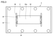
- FIG. 1 is a plan view of a lower mold provided in a compression resin sealing molding apparatus in a first embodiment according to the present invention.
- FIG. 1 is a perspective view of a passage closing member provided in the compression resin sealing molding apparatus in the first embodiment based on the present invention.
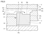
- FIG. 1 is a first partial cross-sectional view of a state in which a passage closing member of the compression resin sealing molding apparatus in the first embodiment according to the present invention is lowered.
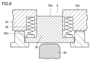
- FIG. 11 is a second partial cross-sectional view of the compression resin sealing molding apparatus in the first embodiment according to the present invention in a state where the passage closing member is lowered.
- FIG. 1 is a first partial cross-sectional view of a state in which a passage closing member of the compression resin sealing molding apparatus in the first embodiment according to the present invention is raised;
- FIG. 10 is a second partial cross-sectional view of the compression resin sealing molding apparatus in the first embodiment according to the present invention, showing a state in which the passage closing member is raised.
- FIG. FIG. 11 is a first explanatory diagram of a compression resin sealing molding apparatus in a second embodiment according to the present invention.
- FIG. 11 is a second explanatory diagram of the compression resin sealing molding apparatus in the second embodiment based on the present invention.
- FIG. 11 is an explanatory diagram of the positional relationship of a plurality of stroke amount regulating member pieces included in a compression resin sealing molding apparatus in a second embodiment based on the present invention.
- FIG. 13 is an explanatory diagram of the positional relationship of a plurality of stroke amount regulating member pieces included in a first modified example of the compression resin sealing molding apparatus in the second embodiment based on the present invention.
- FIG. 13 is an explanatory diagram of the positional relationship of a plurality of stroke amount regulating member pieces included in a second modified example of the compression resin sealing molding apparatus in the second embodiment based on the present invention.
- FIG. FIG. 11 is a conceptual diagram of a compression resin sealing molding apparatus in a third embodiment according to the present invention.
- FIG. 13 is a conceptual diagram of a modified example of the compression resin sealing molding apparatus in the third embodiment according to the present invention.
- FIG. 11 is a first explanatory diagram of the operation of the compression resin sealing molding apparatus in the third embodiment according to the present invention.
- FIG. 13 is a second explanatory diagram of the operation of the compression resin sealing molding apparatus in the third embodiment according to the present invention.
- FIG. 13 is a third explanatory diagram of the operation of the compression resin sealing molding apparatus in the third embodiment based on the present invention.
- FIG. 13 is a fourth explanatory diagram of the operation of the compression resin sealing molding apparatus in the third embodiment based on the present invention.
- 11 is a cross-sectional view of a product obtained as a result of operation of the compression resin sealing molding apparatus in the third embodiment according to the present invention.
- FIG. 11 is a cross-sectional view of a product obtained as a result of operation of the compression resin sealing molding apparatus in the third embodiment according to the present invention.
- FIG. 11 is a cross-
- the compression resin sealing molding device 101 is a compression resin sealing molding device for molding a sealing resin layer so as to partially cover the first surface 10a of the substrate 10, which has a first surface 10a and a second surface 10b that are opposite each other, while sealing the components arranged on the first surface 10a of the substrate 10.
- the components arranged on the first surface 10a of the substrate 10 are omitted from the illustration.
- the compression resin sealing molding device 101 comprises a lower die 3 that contacts the first surface 10a, and an upper die 5 that contacts the second surface 10b.
- Figure 2 shows the lower die 3 alone.
- Figure 3 shows a plan view of the lower die 3.
- the lower die 3 comprises a lower die center portion 32, a stripper portion 33, and a passage closing member 35.
- the lower die center portion 32 has a lower die center upper surface 32a that corresponds to the lower surface of the sealing resin layer.
- the stripper portion 33 is disposed to surround the lower die center portion 32, and contacts the first surface 10a.
- the upper die 5 includes an upper die base portion 51 and an upper die block 52.
- the upper die block 52 is fixed to the underside of the upper die base portion 51.
- the upper die block 52 has an abutment surface 52a facing downward.
- the lower die 3 includes a lower die base portion 31, a stroke amount limiting member 34, and an elastic body 37.
- the stripper portion 33 has a through hole 7.
- the stroke amount limiting member 34 is inserted into the through hole 7.
- the stroke amount limiting member 34 will be described in detail later.
- a notch is provided in part of the inner circumference of the stripper portion 33.
- the passage closure member 35 is disposed inside the notch.
- the cavity 2 is formed by the inner peripheral side surface 33b of the stripper portion 33, the side surface of the passage closure member 35 opposite the stripper portion 33, and the central upper surface 32a of the lower mold.
- the cavity 2 is a space for melting and molding the resin material.
- the stripper portion 33 has a pocket portion 36, which is a recessed portion that contains the resin material that flows out of the cavity 2, outside the cavity 2.
- the passage closure member 35 can be in a first state by descending, which allows the resin material to flow from the cavity 2 to the pocket portion 36, and in a second state by ascending, which inhibits the resin material from flowing from the cavity 2 to the pocket portion 36.
- Figure 4 shows the passage closure member 35 alone.
- the passage closure member 35 has an abutment surface 35a that faces upward at a certain height.
- the passage closure member 35 further has surfaces 35b, 35c, and 35d.
- Surface 35b is a surface that faces upward at a position lower than abutment surface 35a.
- Surface 35c is the side surface that contacts the stripper portion 33.
- Surface 35d is the upper surface of the portion that protrudes to the left and right.
- Figure 5 shows a cross section of the passage closure member 35 and its vicinity.
- Figure 6 shows a view in the direction of arrow 91 in Figure 5.
- An elastic body 38 is interposed between the passage closure member 35 and the stripper portion 33.
- the elastic body 38 is installed on the surface 35d of the protruding portion.
- the elastic body 38 may be, for example, a spring.
- the passage closure member 35 is urged downward by the elastic body 38.
- a push-up pin 39 is disposed below the passage closure member 35. In the state shown in Figure 6, i.e., when the push-up pin 39 is not pushing up the passage closure member 35, the passage closure member 35 is in a lowered state due to the action of the elastic body 38.
- Figures 5 and 6 show the state in which the passage closing member 35 is lowered, which corresponds to the "first state" described above.
- the passage 6 is open. Resin material that overflows from the cavity 2 can flow through the passage 6 toward the pocket portion 36, as shown by the arrow 92.
- Figure 7 the abutment surface 35a of the passage closure member 35 abuts against the substrate 10.
- the passage 6 is blocked.
- the surface 35b forms part of the bottom surface of the pocket portion 36.
- the push-up pin 39 pushes up the passage closure member 35 in the direction of the arrow 93.
- the push-up pin 39 pushes up the passage closure member 35 against the downward bias of the elastic body 38 against the passage closure member 35.
- the abutment surface 35a of the passage closure member 35 and the upper surface 33a of the stripper portion 33 are located on the same plane.
- the end of the abutment surface 35a closer to the cavity 2 is closer to the cavity 2 than the outer edge of the first surface 10a, and the end of the abutment surface 35a farther from the cavity 2 is farther from the cavity 2 than the outer edge of the first surface 10a.
- the abutment surface 35a is positioned so as to straddle the outer edge of the first surface 10a. In other words, in the second state, a part of the abutment surface 35a is in surface contact with a part of the first surface 10a, as shown in FIG. 7.
- the resin overflowing from the cavity 2 in the first state, can be released into the pocket portion 36, and then by switching to the second state, the outflow of the resin can be prevented.
- the contact surface 35a of the passage closing member 35 contacts the first surface 10a of the substrate 10, so that the resin overflowing from the cavity 2 can be prevented from adhering to the surface of the outer edge of the substrate.
- FIG. 4 a perspective view of the passage closure member 35 is shown in FIG. 4, the shape shown in FIG. 4 is merely one example.
- the passage closure member 35 only needs to have the function of allowing the resin material to escape to the pocket portion 36 in the first state and preventing the outflow of the resin material in the second state, and the shape of the passage closure member 35 is not limited to that shown in FIG. 4.
- the passage closure member 35 is, more precisely, an assembly of a plurality of passage closure member pieces.
- the passage closure member 35 includes four passage closure member pieces.
- the passage closure member 35 includes a plurality of passage closure member pieces, and it is preferable that the plurality of passage closure member pieces are arranged symmetrically along the first and second sides of the cavity that face each other.
- the resin overflowing from the cavity 2 can be discharged in parallel from a plurality of places, so that it can be discharged efficiently.
- the cavity 2 is displayed as a horizontally long rectangular recess, but the left side of this rectangle is the first side and the right side is the second side.
- the first and second sides may be assigned in reverse. In any case, both the first and second sides are short sides.
- the cavity 2 has two long sides that are parallel to each other and two short sides that are parallel to each other, and it is preferable that both the first and second sides are short sides.
- Patent Documents 1 and 2 (Second Objective) The methods and devices described in Patent Documents 1 and 2 are believed to be capable of making the resin layer in the resulting product have a desired thickness.
- the thickness of the substrate generally varies. Since the thickness of the resulting product is the sum of the thickness of the substrate and the thickness of the resin layer, even if the thickness of the resin layer can be accurately achieved, the variation in the thickness of the product includes components derived from the variation in the thickness of the substrate, and therefore the variation cannot be sufficiently suppressed.
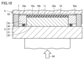
- FIG. 9 shows a resin sheet 11 placed in the cavity 2 of the compression resin sealing molding device in this embodiment, with the lower die 3 brought relatively close to the upper die 5 to a certain extent.
- the lower die 3 is raised as shown by the arrow 94.
- the upper surface 33a of the stripper portion 33 is already in contact with the first surface 10a of the substrate 10.
- the second surface 10b of the substrate 10 is in contact with the contact surface 52a of the upper die block 52.
- a stroke amount limiting member 34 is fixed to the upper surface of the lower die base portion 31.
- the stroke amount limiting member 34 is a rod-shaped member having a certain length. The upper part of the stroke amount limiting member 34 is inserted into the through hole 7 provided in the stripper portion 33.
- An elastic body 37 is interposed between the stripper portion 33 and the lower mold base portion 31.
- the elastic body 37 may be, for example, a spring.
- the lower mold base portion 31 continues to rise even after the stripper portion 33 abuts against the substrate 10.
- the rise of the lower mold base portion 31 continues while compressing the elastic body 37.
- the lower mold center portion 32 is fixed to the upper side of the lower mold base portion 31, the lower mold center portion 32 also rises together with the lower mold base portion 31.
- the upper end of the stroke amount control member 34 protrudes from the through hole 7 and abuts against the abutment surface 52a of the upper mold block 52.
- the stroke amount control member 34 is a member having a certain length and sufficient rigidity, the lower mold base portion 31 cannot rise any further.
- the height difference between the upper end of the stroke amount limiting member 34 and the central upper surface 32a of the lower die is maintained constant, so the central upper surface 32a of the lower die stops at a position a certain distance from the contact surface 52a of the upper die block 52.
- This compression resin sealing molding device in this embodiment can be expressed as follows.
- This compression resin sealing molding device is a compression resin sealing molding device for molding a sealing resin layer so as to partially cover the first surface 10a of the substrate 10 while sealing components arranged on the first surface 10a of the substrate 10 having a first surface and a second surface that are opposite to each other.
- This compression resin sealing molding device includes a lower mold 3 that abuts against the first surface 10a and an upper mold 5 that abuts against the second surface 10b.
- the lower mold 3 includes a lower mold base portion 31, a lower mold center portion 32 having a lower mold central upper surface 32a corresponding to the lower surface of the sealing resin layer, a stripper portion 33 that is arranged to surround the lower mold center portion 32 and abuts against the first surface 10a, and a stroke amount regulating member 34 fixed to the lower mold base portion 31 so as to protrude from the lower mold base portion 31.
- the inner peripheral side surface 33b of the stripper portion 33 and the lower mold central upper surface 32a form a cavity 2 for melting and molding the resin material.
- the stripper portion 33 is supported by the lower die base portion 31 via an elastic body 37.
- the stroke amount control member 34 abuts against the upper die 5, thereby restricting the distance between the abutment surface 52a, which is the surface that abuts against the second surface 10b of the upper die 5, and the central upper surface 32a of the lower die so that it does not become smaller than a certain value.
- the stroke amount restriction member 34 is not limited to a single member.
- the stroke amount restriction member 34 includes multiple stroke amount restriction member pieces.
- the multiple stroke amount restriction member pieces are arranged as shown in the plan view of FIG. 11. That is, the multiple stroke amount restriction member pieces are arranged so as to surround the cavity 2.
- the lower mold 3 is rectangular in plan view, and four stroke amount restriction member pieces are arranged at equal intervals along each of the two long sides. That is, a total of eight stroke amount restriction member pieces are arranged.
- the number and arrangement are not limited to this. For example, the number and arrangement may be as shown in FIG. 12 and FIG. 13.
- the stroke amount regulating member 34 restricts the distance between the abutment surface 52a of the upper die 5 and the central upper surface 32a of the lower die so that it does not become smaller than a certain value, so that the overall thickness of the product, which is the sum of the thickness of the substrate 10 and the thickness of the sealing resin, can be made constant.
- the overall thickness of the obtained product can be made constant.
- the stripper section 3 and the stroke amount control member 34 can be displaced separately. If the thickness of the desired product changes, this can be accommodated by replacing the stroke amount control member 34 with one of a different length.
- the stroke amount control member 34 includes a plurality of stroke amount control member pieces, which are preferably arranged to surround the cavity 2.
- the lower mold 3 includes a lower mold base portion 31 and a stroke amount regulating member 34 fixed to the lower mold base portion 31 so as to protrude from the lower mold base portion 31, the stripper portion 33 is supported by the lower mold base portion 31 via an elastic body 37, and it is preferable that the stroke amount regulating member 34 abuts against the upper mold 5 to restrict the distance between the surface of the upper mold 5 abutting against the second surface 10b and the central upper surface 32a of the lower mold so as not to be smaller than a certain value.
- the stroke amount control member 34 preferably includes a plurality of stroke amount control member pieces, which are arranged to surround the cavity 2.
- FIG. 14 An outline of a compression resin encapsulation molding apparatus 102 according to the present embodiment is shown in Fig. 14.
- the basic configuration of the compression resin encapsulation molding apparatus 102 is similar to that described in the first embodiment.
- the surface of the upper die 5 facing the cavity 2 is covered with a release sheet 62.
- the contact surface 52a of the upper die 5 is covered with the release sheet 62.
- the effects described in the first embodiment can be obtained. Furthermore, in this embodiment, the resin material overflowing from the cavity 2 comes into contact with the release sheet 62 without directly contacting the contact surface 52a of the upper die 5. The resin material that comes into contact with the release sheet 62 can be easily separated from the release sheet 62. Therefore, it is possible to prevent the overflowing resin material from adhering to and remaining on the upper die 5.
- a configuration like the compression resin sealing molding device 103 shown in FIG. 15 may be adopted.
- the surface of the upper die 5 facing the cavity 2, i.e., the abutment surface 52a, is covered with a release sheet 62, and further, the surface of the lower die 3 facing the upper die 5, i.e., the upper surface 33a, and the inner surface of the cavity 2 are covered with a release sheet 61.
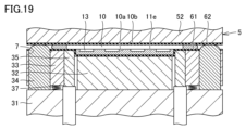
- FIG. 16 to 19 the shape of the passage closing member 35 is shown in a simplified form. In reality, the passage closing member 35 may have a shape as described in embodiment 1. Also, although the pocket portion 36 is not shown, a pocket portion 36 having a structure as described in embodiment 1 may be provided immediately outside the passage 6.
- the substrate 10 is sandwiched between the upper mold 5 and the stripper portion 33.
- a cross section passing through the passage 6 is shown, so the passage 6 is visible, but the upper surface 33a of the stripper portion 33 is not visible abutting against the first surface 10a of the substrate 10.
- the upper surface 33a of the stripper portion 33 is abutting against the lower surface of the substrate 10.
- the substrate 10 is sandwiched between the abutment surface 52a of the upper mold 5 and the upper surface 33a of the stripper portion 33.
- the contact surface 52a of the upper mold 5 and the upper surface 33a of the stripper portion 33 are not in direct contact with the substrate 10 because the release sheets 61 and 62 are interposed between them, but the presence of the release sheets 61 and 62 will be ignored when discussing which member is in contact with the substrate 10.
- Components 13 are mounted on the underside of the substrate 10.
- the components 13 may be electronic components.
- a resin sheet 11 is disposed within the cavity 2. At this point, the resin sheet 11 does not need to be melted. At this point, the passage 6 is open. The components 13 are in contact with the resin sheet 11.
- the passage closing member 35 is raised to close the passage 6. In this state, pressure and heat are applied.
- the resin sheet 11 melts and becomes resin 11e.
- the lower die base portion 31 is raised. As the lower die base portion 31 rises, the lower die center portion 32 rises.
- the resin 11e fills the gaps between the components 13. The resin 11e comes into contact with the first surface 10a of the substrate 10.
- the passage closing member 35 is lowered. This opens the passage 6, and the molten resin 11e flows out of the cavity 2 through the passage 6. Although the pocket portion 36 is not shown in Figure 18, the molten resin 11e may flow into the pocket portion 36.
- the passage closing member 35 is raised to close the passage 6, as shown in FIG. 19. In this way, the resin 11e that has been confined to seal the component 13 on the first surface 10a of the substrate 10 is separated from the excess resin 11e that has spilled out to the outside of the substrate 10.
- FIG. 20 a product as shown in FIG. 20 can be removed.
- This product comprises a substrate 10, a component 13, and sealing resin 14.
- the sealing resin 14 is attached to the first surface 10a of the substrate 10.
- the component 13 is sealed with the sealing resin 14.
- FIG. 19 there is excess resin 11e that has spilled out onto the outside of the substrate 10, but due to the action of the release sheets 61, 62, the excess resin 11e does not adhere to the upper die 5 and the lower die 3, and can be easily removed.
- a compression resin encapsulation molding apparatus for molding an encapsulation resin layer so as to partially cover a first surface of a substrate while encapsulating a component disposed on the first surface of the substrate, the device comprising: A lower mold abutting on the first surface; an upper mold abutting on the second surface, The lower mold is a lower mold central portion having a lower mold central upper surface corresponding to a lower surface of the encapsulating resin layer; a stripper portion disposed to surround a central portion of the lower die and in contact with the first surface; a passage closing member; A notch is provided in a part of an inner periphery of the stripper portion, The passage closing member is disposed within the notch, a cavity for melting and molding a resin material is formed by an inner peripheral side surface of the stripper portion, a side surface of the passage closing member opposite to the stripper portion, and a central upper surface of the lower die; the stripper portion has a pocket portion, which is a
- the passage closure member includes a plurality of passage closure member pieces;
- the cavity has two long sides parallel to each other and two short sides parallel to each other, 3.
- the lower mold is A lower die base portion, a stroke amount limiting member fixed to the lower die base portion so as to protrude from the lower die base portion, the stripper portion is supported by the lower die base portion via an elastic body, A compression resin sealing molding apparatus described in any one of appendix 1 to 3, wherein the stroke amount regulating member abuts against the upper mold, thereby restricting the distance between the surface of the upper mold abutting the second surface and the central upper surface of the lower mold so that it does not become smaller than a certain value.
- a compression resin encapsulation molding apparatus for molding an encapsulation resin layer so as to partially cover a first surface of a substrate while encapsulating a component disposed on the first surface of the substrate, the device comprising: A lower mold abutting on the first surface; an upper mold abutting on the second surface,
- the lower mold is A lower die base portion, a lower mold central portion having a lower mold central upper surface corresponding to a lower surface of the encapsulating resin layer; a stripper portion disposed to surround the central portion of the lower die and in contact with the first surface; a stroke amount limiting member fixed to the lower die base portion so as to protrude from the lower die base portion, a cavity for melting and molding a resin material is formed by an inner peripheral side surface of the stripper portion and a central upper surface of the lower die, the stripper portion is supported by the lower die base portion via an elastic body,
- a compression resin sealing molding apparatus in which the stroke amount control member abuts against the upper mold, thereby restricting the distance
Landscapes
- Engineering & Computer Science (AREA)
- Mechanical Engineering (AREA)
- Casting Or Compression Moulding Of Plastics Or The Like (AREA)
- Moulds For Moulding Plastics Or The Like (AREA)
Priority Applications (2)
| Application Number | Priority Date | Filing Date | Title |
|---|---|---|---|
| JP2024559990A JPWO2024111255A1 (https=) | 2022-11-21 | 2023-10-04 | |
| CN202380078438.9A CN120202102A (zh) | 2022-11-21 | 2023-10-04 | 压缩树脂密封成形装置 |
Applications Claiming Priority (2)
| Application Number | Priority Date | Filing Date | Title |
|---|---|---|---|
| JP2022185973 | 2022-11-21 | ||
| JP2022-185973 | 2022-11-21 |
Publications (1)
| Publication Number | Publication Date |
|---|---|
| WO2024111255A1 true WO2024111255A1 (ja) | 2024-05-30 |
Family
ID=91195424
Family Applications (1)
| Application Number | Title | Priority Date | Filing Date |
|---|---|---|---|
| PCT/JP2023/036184 Ceased WO2024111255A1 (ja) | 2022-11-21 | 2023-10-04 | 圧縮樹脂封止成形装置 |
Country Status (3)
| Country | Link |
|---|---|
| JP (1) | JPWO2024111255A1 (https=) |
| CN (1) | CN120202102A (https=) |
| WO (1) | WO2024111255A1 (https=) |
Citations (5)
| Publication number | Priority date | Publication date | Assignee | Title |
|---|---|---|---|---|
| JP2013184389A (ja) * | 2012-03-08 | 2013-09-19 | Towa Corp | 電子部品の樹脂封止成形品の製造方法、圧縮成形用下金型及び樹脂封止装置 |
| JP2014531340A (ja) * | 2011-09-06 | 2014-11-27 | オスラム オプト セミコンダクターズ ゲゼルシャフト ミット ベシュレンクテル ハフツングOsram Opto Semiconductors GmbH | シリコーン部材を製造するための圧縮工具およびシリコーン部材を製造するための方法 |
| JP2017143232A (ja) * | 2016-02-13 | 2017-08-17 | Towa株式会社 | 樹脂封止装置及び樹脂封止方法並びに樹脂封止用の成形型 |
| JP2017224842A (ja) * | 2017-08-10 | 2017-12-21 | Towa株式会社 | 樹脂封止電子部品の製造方法及び樹脂封止電子部品の製造装置 |
| JP2018144371A (ja) * | 2017-03-07 | 2018-09-20 | Towa株式会社 | 樹脂封止装置、樹脂成形方法および樹脂成形品の製造方法 |
-
2023
- 2023-10-04 WO PCT/JP2023/036184 patent/WO2024111255A1/ja not_active Ceased
- 2023-10-04 CN CN202380078438.9A patent/CN120202102A/zh active Pending
- 2023-10-04 JP JP2024559990A patent/JPWO2024111255A1/ja active Pending
Patent Citations (5)
| Publication number | Priority date | Publication date | Assignee | Title |
|---|---|---|---|---|
| JP2014531340A (ja) * | 2011-09-06 | 2014-11-27 | オスラム オプト セミコンダクターズ ゲゼルシャフト ミット ベシュレンクテル ハフツングOsram Opto Semiconductors GmbH | シリコーン部材を製造するための圧縮工具およびシリコーン部材を製造するための方法 |
| JP2013184389A (ja) * | 2012-03-08 | 2013-09-19 | Towa Corp | 電子部品の樹脂封止成形品の製造方法、圧縮成形用下金型及び樹脂封止装置 |
| JP2017143232A (ja) * | 2016-02-13 | 2017-08-17 | Towa株式会社 | 樹脂封止装置及び樹脂封止方法並びに樹脂封止用の成形型 |
| JP2018144371A (ja) * | 2017-03-07 | 2018-09-20 | Towa株式会社 | 樹脂封止装置、樹脂成形方法および樹脂成形品の製造方法 |
| JP2017224842A (ja) * | 2017-08-10 | 2017-12-21 | Towa株式会社 | 樹脂封止電子部品の製造方法及び樹脂封止電子部品の製造装置 |
Also Published As
| Publication number | Publication date |
|---|---|
| CN120202102A (zh) | 2025-06-24 |
| JPWO2024111255A1 (https=) | 2024-05-30 |
Similar Documents
| Publication | Publication Date | Title |
|---|---|---|
| US5744084A (en) | Method of improving molding of an overmolded package body on a substrate | |
| US7681308B2 (en) | Fabrication method of semiconductor integrated circuit device | |
| TWI531459B (zh) | Compression forming die and compression forming method | |
| JP6541746B2 (ja) | 樹脂成形装置及び樹脂成形品の製造方法 | |
| JP6804275B2 (ja) | 成形型、樹脂成形装置及び樹脂成形方法 | |
| KR101964034B1 (ko) | 기판상에 균일한 클램핑 압력을 가하기 위한 몰딩 시스템 | |
| JP6861609B2 (ja) | 樹脂成形装置及び樹脂成形品の製造方法 | |
| CN102456583A (zh) | 半导体芯片的压缩成形方法及压缩成形模具 | |
| JP2018069503A (ja) | 樹脂封止用金型、一次成形金型、二次成形金型及び樹脂成形品の製造方法 | |
| WO2024111255A1 (ja) | 圧縮樹脂封止成形装置 | |
| TW201902650A (zh) | 模製模具及樹脂模製方法 | |
| JP6749286B2 (ja) | モールド金型及び樹脂モールド方法 | |
| TW201401459A (zh) | 半導體裝置之製造方法及半導體裝置 | |
| JP4153862B2 (ja) | 半導体樹脂封止用金型 | |
| CN100536100C (zh) | 电子元件的树脂密封成形装置 | |
| US20210278263A1 (en) | Flow-Rate Sensor | |
| JP6195071B2 (ja) | 表皮一体樹脂成形装置 | |
| JP4563426B2 (ja) | 樹脂モールド金型 | |
| WO2025243753A1 (ja) | 圧縮樹脂封止成形装置 | |
| JP4830711B2 (ja) | 多数個取りインサート成形装置 | |
| JP6266888B2 (ja) | ダミーフレーム、凸部部材、ダミーフレームの作製方法、樹脂流動性評価方法、樹脂モールド方法、及びモールド金型の製造方法 | |
| KR20190090777A (ko) | 압축 성형 장치, 압축 성형 방법 및 압축 성형품의 제조 방법 | |
| JP6296195B1 (ja) | 樹脂封止用金型の調整方法及び樹脂封止用金型 | |
| JPWO2024111255A5 (https=) | ||
| JP2008166395A (ja) | 半導体装置の製造方法 |
Legal Events
| Date | Code | Title | Description |
|---|---|---|---|
| 121 | Ep: the epo has been informed by wipo that ep was designated in this application |
Ref document number: 23894267 Country of ref document: EP Kind code of ref document: A1 |
|
| WWE | Wipo information: entry into national phase |
Ref document number: 2024559990 Country of ref document: JP |
|
| WWE | Wipo information: entry into national phase |
Ref document number: 202380078438.9 Country of ref document: CN |
|
| NENP | Non-entry into the national phase |
Ref country code: DE |
|
| WWP | Wipo information: published in national office |
Ref document number: 202380078438.9 Country of ref document: CN |
|
| 122 | Ep: pct application non-entry in european phase |
Ref document number: 23894267 Country of ref document: EP Kind code of ref document: A1 |