WO2024105799A1 - カメラユニット - Google Patents
カメラユニット Download PDFInfo
- Publication number
- WO2024105799A1 WO2024105799A1 PCT/JP2022/042494 JP2022042494W WO2024105799A1 WO 2024105799 A1 WO2024105799 A1 WO 2024105799A1 JP 2022042494 W JP2022042494 W JP 2022042494W WO 2024105799 A1 WO2024105799 A1 WO 2024105799A1
- Authority
- WO
- WIPO (PCT)
- Prior art keywords
- holder
- board
- camera unit
- imaging
- rigid
- Prior art date
- Legal status (The legal status is an assumption and is not a legal conclusion. Google has not performed a legal analysis and makes no representation as to the accuracy of the status listed.)
- Ceased
Links
Images




Classifications
-
- H—ELECTRICITY
- H04—ELECTRIC COMMUNICATION TECHNIQUE
- H04N—PICTORIAL COMMUNICATION, e.g. TELEVISION
- H04N23/00—Cameras or camera modules comprising electronic image sensors; Control thereof
- H04N23/50—Constructional details
Definitions
- This disclosure relates to a camera unit.
- the camera unit shown in Figure 1 of Patent Document 1 does not use connectors to connect multiple boards, but requires multiple parts, such as a front panel, a rear panel, and a top panel, to secure the multiple boards together, making it difficult to miniaturize.
- This disclosure was made in consideration of the above problems, and aims to provide an in-vehicle camera unit that can be miniaturized.
- the camera unit of the present disclosure is equipped with a camera that captures images of vehicle occupants, and includes a rigid-flexible board and a holder.
- the rigid-flexible board is composed of multiple boards connected by flexible cables.
- the holder is a single component that directly fixes the rigid-flexible board and is the outermost component of the camera unit.
- the multiple boards that make up the rigid-flexible board include an imaging board and a transmission board.
- the imaging board is equipped with a light receiving element of the camera.
- the transmission board is equipped with an external output connector for connecting the rigid-flexible board to the outside of the camera unit.
- the holder fixes the imaging board and the transmission board in a state where they face in different directions.
- the light receiving element and the external output connector are exposed from the holder in different directions when the rigid-flexible board is fixed to the holder.
- the camera unit of the present disclosure multiple substrates are fixed directly to the holder, which is a single component and the outermost component, eliminating the need for multiple components for fixing multiple substrates, thereby realizing a compact camera unit.
- the multiple substrates are fixed to the holder while facing in different directions, the dimensions of the camera unit in a plan view can be reduced.
- FIG. 1 is a diagram showing a state in which a camera unit according to a first embodiment is arranged in a vehicle.
- FIG. 2 is a perspective view of the camera unit according to the first embodiment, as viewed from the screen side.
- FIG. 2 is a perspective view of the camera unit according to the first embodiment, as viewed from the cover side.
- FIG. 2 is an exploded perspective view of the camera unit according to the first embodiment.
- 1 is a diagram showing a state in which the rigid-flexible substrate according to the first embodiment is unfolded;
- 5A to 5C are diagrams showing how an imaging substrate is fixed to a holder in the first embodiment.
- 6A and 6B are diagrams showing how a transmission board is fixed to a holder in accordance with the first embodiment;
- FIG. 1 is a diagram showing a state in which a camera unit according to a first embodiment is arranged in a vehicle.
- FIG. 2 is a perspective view of the camera unit according to the first embodiment, as viewed from the screen
- FIG. 11 is a perspective view of a camera unit according to a second embodiment, as viewed from the screen side.
- FIG. 11 is a perspective view of a camera unit according to a second embodiment, as viewed from the cover side.
- FIG. 11 is a perspective view of a camera unit according to a second embodiment, as viewed from the cover side.
- 13A and 13B are diagrams showing how an imaging substrate is fixed to a holder in accordance with a second embodiment.
- 13A and 13B are diagrams showing how a transmission board is fixed to a holder in accordance with the second embodiment;
- First embodiment> 1 is a diagram showing a state in which a camera unit 1A according to the first embodiment is mounted on a vehicle 100.
- the camera unit 1A is arranged, for example, on the windshield or a pillar of the vehicle 100 facing the interior of the vehicle, and captures images of occupants of the vehicle 100, such as a driver 101. Images captured by the camera unit 1A are output to a device external to the camera unit 1A (hereinafter referred to as an external device), and are used, for example, to monitor occupants looking away, falling asleep, or losing their posture.
- an external device a device external to the camera unit 1A
- FIG. 2 is a perspective view of camera unit 1A seen from the screen 4 side
- FIG. 3 is a perspective view of camera unit 1A seen from the cover 2A side
- FIG. 4 is an exploded perspective view of camera unit 1A.
- Camera unit 1A includes a camera that captures images of vehicle occupants and a lighting device that illuminates the occupants. However, the lighting device may be configured separately from camera unit 1A.
- Camera unit 1A includes a cover 2A, a holder 3A, a screen 4, a rigid-flexible board 6, an external output connector 7, and a camera lens 8.
- the holder 3A is configured with a bottom portion 31 that forms the bottom surface of the holder 3A, and multiple side portions 32 that form the sides of the holder 3A.
- the multiple side portions 32 are connected to the bottom portion 31 and are arranged approximately perpendicular to the bottom portion 31.
- a part of the rigid-flexible board 6 is stored in the internal space 33 of the holder 3A that is surrounded by the bottom portion 31 and the multiple side portions 32.
- a screw hole is formed in the bottom portion 31 of the holder 3A.
- the camera lens 8 is fitted into this screw hole from the bottom side in Figure 4.
- the rigid-flexible board 6 is made up of multiple boards connected by flexible cables 11.
- the multiple boards that make up the rigid-flexible board 6 include an imaging board 9 and a transmission board 10. Because the imaging board 9 and the transmission board 10 are connected by flexible cables 11, there is no connector for connecting the two boards.
- the imaging board 9 is equipped with a camera light receiving element and an illumination device (not shown). If the illumination device is configured separately from the camera unit 1A, the imaging board 9 will not be equipped with an illumination device.
- the transmission board 10 is equipped with an external output connector 7 for connecting the rigid-flexible board 6 to an external device.
- the light receiving signal of the light receiving element of the camera mounted on the imaging board 9 is transmitted from the external output connector 7 to the external device and is used to monitor whether the occupant is looking away, falling asleep, or losing posture.
- Figure 4 shows the state in which the flexible cable 11 is bent and the imaging board 9 and the transmission board 10 overlap. In this state, the imaging board 9 and the transmission board 10 are fixed to the holder 3A with screws 5.
- Figure 5 shows the state in which the rigid-flexible board 6 has been removed from the holder 3A and the imaging board 9 and the transmission board 10 are unfolded.
- a screen 4 is attached to the bottom surface 31 of the holder 3A so as to cover the camera lens 8.
- the screen 4 is made of a material that transmits light. By covering the camera lens 8 with the screen 4, the camera lens 8 is protected from scratches and dirt.
- the side opposite the bottom surface 31 of the holder 3A i.e., the upper side in FIG. 4, is covered with a cover 2A.
- the rigid-flexible board 6 fixed to the holder 3A is covered with the cover 2A.
- the cover 2A has an opposing surface 21 that faces the transmission board 10 fixed to the holder 3A, and a number of side surfaces 22 connected to the opposing surface 21.
- a hole 23 is provided in the opposing surface 21 of the cover 2A, and a connection between the external output connector 7 and an external device is realized through this hole 23.
- Figures 6 and 7 are perspective views showing the procedure for attaching the rigid-flexible board 6 to the holder 3A.
- the imaging board 9 is inserted into the internal space 33 of the holder 3A, and the imaging board 9 is fixed to the bottom surface 31 of the holder 3A with the screws 5. At this time, the fixing direction by the screws 5 is from top to bottom in FIG. 6. With the imaging board 9 fixed to the holder 3A, the light receiving element and lighting device of the camera mounted on the imaging board 9 are exposed from the holes in the bottom surface 31 of the holder 3A and face the camera lens 8.
- the flexible cable 11 is bent so that the transmission board 10 overlaps the imaging board 9, and then the transmission board 10 is fixed to the upper end surface 34 of the side portion 32 of the holder 3A with the screw 5.
- This state is shown in Figure 7.
- the fixing direction by the screw 5 is from top to bottom in Figure 7.
- the fixing directions of the imaging board 9 and the transmission board 10 to the holder 3A are both from top to bottom in Figures 6 and 7, and are the same. This makes it possible to reduce the number of work steps in manufacturing the camera unit 1A and reduce manufacturing costs.
- the transmitting board 10 When the transmitting board 10 is fixed to the upper end surface 34 of the side surface portion 32 of the holder 3A, the end surface of the transmitting board 10 is flush with the side surface portion 32 of the holder 3A. With this configuration, the mounting area of the transmitting board 10 is maximized while the transmitting board 10 is fixed to the holder 3A. In addition, the area of the transmitting board 10 can be made larger than that of the imaging board 9 stored in the internal space 33 of the holder 3A.
- the transmitting board 10 When the transmitting board 10 is fixed to the holder 3A, the external output connector 7 mounted on the transmitting board 10 is exposed from the holder 3A in the upward direction in FIG. 7. Meanwhile, the light receiving element and lighting device of the camera mounted on the imaging board 9 are exposed from the bottom surface 31 of the holder 3A in the downward direction in FIG. 7. In this way, the imaging board 9 and the transmitting board 10 are attached in different directions to the holder 3A, and therefore the external output connector 7 mounted on the transmitting board 10 and the light receiving element etc. mounted on the imaging board 9 are exposed in different directions from the holder 3A.
- the cover 2A fits into the side portion 32 of the holder 3A.
- the cover 2A, the side of the bottom portion 31 of the holder 3A, and the screen 4 are the outermost parts that make up the outermost portion of the camera unit 1A.
- the rigid-flexible board 6, which is made up of multiple boards including the imaging board 9 and the transmission board 10, can be fixed directly to the holder 3A, which is one of the outermost components of the camera unit 1A.
- the camera unit 1A does not lose space due to the fixing of the boards or the connection structure of the boards, making it possible to achieve a compact size.
- the rigid-flexible substrate 6 may include at least one other substrate (hereinafter referred to as an additional substrate) in addition to the imaging substrate 9 and the transmission substrate 10.
- the additional substrate is connected to the imaging substrate 9 and the transmission substrate 10 by a flexible cable 11.
- the additional substrate is fixed to the holder 3A while being sandwiched between the imaging substrate 9 and the transmission substrate 10. More specifically, the rigid-flexible substrate 6 is bent at the flexible cable 11 so that the imaging substrate 9, the additional substrate, and the transmission substrate 10 overlap in that order, and is fixed to the holder 3A.
- the positional relationship of the imaging board 9 and the transmission board 10 to the holder 3A may be reversed from that described above. That is, the transmission board 10 may be fixed to the bottom surface 31 in the internal space 33 of the holder 3A, and the imaging board 9 may be fixed to the upper end surface 34 of the side surface 32 of the holder 3A. This allows the imaging board 9 to have a larger area than the transmission board 10. In this case, the positional relationship of the cover 2A and the screen 4 to the holder 3A is changed as appropriate.
- the camera unit 1A includes a rigid-flexible substrate 6 and a holder 3A.
- the rigid-flexible substrate 6 is composed of multiple substrates connected by flexible cables 11.
- the holder 3A is a single component that directly fixes the rigid-flexible substrate 6 and is the outermost component of the camera unit 1A.
- the multiple substrates that make up the rigid-flexible substrate 6 include an imaging substrate 9 and a transmission substrate 10.
- the imaging substrate 9 is equipped with a light receiving element of the camera.
- the transmission substrate 10 is equipped with an external output connector 7 for connecting the rigid-flexible substrate 6 to the outside of the camera unit 1A.
- the holder 3A fixes the imaging substrate 9 and the transmission substrate 10 in a state in which they face in different directions.
- the light receiving element and the external output connector 7 are exposed in different directions from the holder 3A when the rigid-flexible substrate 6 is fixed to the holder 3A.
- the imaging board 9 and the transmission board 10 are fixed to the holder 3A facing in different directions, it is possible to reduce the dimensions of the camera unit 1A in a plan view. This allows the camera unit 1A to be made more compact.
- the holder 3A fixes the imaging board 9 and the transmission board 10 in an overlapping state. Then, with the rigid-flexible board 6 fixed to the holder 3A, the light receiving element and the external output connector 7 are exposed in opposite directions from each other from the holder 3A. With this configuration, when manufacturing the camera unit 1A, the imaging board 9 and the transmission board 10 can be fixed to the holder 3A from the same direction. This makes it possible to reduce the number of work processes when manufacturing the camera unit 1A, and to reduce manufacturing costs.
- the holder 3A includes a bottom portion 31 that forms the bottom surface of the holder 3A and has a hole, and a plurality of side portions 32 that are connected to the bottom portion 31, form the side surfaces of the holder 3A, and form an internal space 33 between the bottom portion 31 and the side portions 32.
- the imaging board 9 is fixed to the internal space 33 so that the light receiving element is exposed from the hole in the bottom portion 31, and the transmission board 10 is mounted on the upper end surfaces 34 of the plurality of side portions 32 so that the external output connector 7 is exposed from the holder 3A.
- the transmission board 10 can be made larger in area than the imaging board 9.
- Second embodiment In the camera unit 1A according to the first embodiment, the imaging board 9 and the transmission board 10 are stacked on top of each other and fixed to the holder 3A. In contrast, in the camera unit 1B according to the second embodiment, the imaging board 9 and the transmission board 10 are arranged in an L shape and fixed to the holder 3B. Even with this configuration, the imaging board 9 and the transmission board 10 are fixed to the holder 3B facing in different directions, so that the camera unit 1B can be made smaller.
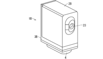
- FIG. 8 is a perspective view of camera unit 1B seen from the screen 4 side
- FIG. 9 is a perspective view of camera unit 1B seen from the cover 2B side
- FIG. 10 is an exploded perspective view of camera unit 1B.
- Camera unit 1B is configured with cover 2B, holder 3B, screen 4, rigid-flexible board 6, external output connector 7, and camera lens 8.
- imaging board 9 and transmission board 10 are arranged and fixed in an L shape, so the shape of holder 3B is different from holder 3A of embodiment 1.
- the shape of cover 2B is also different from cover 2A of embodiment 1.
- Figures 11 and 12 are perspective views showing the procedure for attaching the rigid-flexible board 6 to the holder 3B.
- the imaging board 9 is inserted into the internal space 33 of the holder 3B, and the imaging board 9 is fixed to the bottom surface 31 of the holder 3B with the screws 5. With the imaging board 9 fixed to the holder 3B, the light receiving element and the lighting device of the camera mounted on the imaging board 9 are exposed from the holes in the bottom surface 31 of the holder 3B, and face the camera lens 8.
- the flexible cable 11 is bent so that the transmission board 10 is at a substantially right angle to the imaging board 9, and then the transmission board 10 is fixed to the side end surface 35 of the side portion 32 of the holder 3B with the screws 5.
- This state is shown in Figure 12.
- the imaging board 9 and the transmission board 10 are fixed to the holder 3B in an L-shaped arrangement. This reduces the dimensions of the camera unit 1B in a plan view, achieving a compact camera unit 1B.
- 1A, 1B camera unit 2A, 2B cover, 3A, 3B holder, 31 bottom surface, 32 side surface, 33 internal space, 34 top surface, 35 side surface, 4 screen, 5 screws, 6 rigid-flexible board, 7 external output connector, 8 camera lens, 9 imaging board, 10 transmission board, 11 flexible cable.
Landscapes
- Engineering & Computer Science (AREA)
- Multimedia (AREA)
- Signal Processing (AREA)
- Studio Devices (AREA)
- Camera Bodies And Camera Details Or Accessories (AREA)
Priority Applications (2)
| Application Number | Priority Date | Filing Date | Title |
|---|---|---|---|
| JP2024558556A JP7646102B2 (ja) | 2022-11-16 | 2022-11-16 | カメラユニット |
| PCT/JP2022/042494 WO2024105799A1 (ja) | 2022-11-16 | 2022-11-16 | カメラユニット |
Applications Claiming Priority (1)
| Application Number | Priority Date | Filing Date | Title |
|---|---|---|---|
| PCT/JP2022/042494 WO2024105799A1 (ja) | 2022-11-16 | 2022-11-16 | カメラユニット |
Publications (1)
| Publication Number | Publication Date |
|---|---|
| WO2024105799A1 true WO2024105799A1 (ja) | 2024-05-23 |
Family
ID=91084071
Family Applications (1)
| Application Number | Title | Priority Date | Filing Date |
|---|---|---|---|
| PCT/JP2022/042494 Ceased WO2024105799A1 (ja) | 2022-11-16 | 2022-11-16 | カメラユニット |
Country Status (2)
| Country | Link |
|---|---|
| JP (1) | JP7646102B2 (https=) |
| WO (1) | WO2024105799A1 (https=) |
Citations (2)
| Publication number | Priority date | Publication date | Assignee | Title |
|---|---|---|---|---|
| JP2009107393A (ja) * | 2007-10-26 | 2009-05-21 | Panasonic Corp | 車載カメラ |
| JP2011139138A (ja) * | 2009-12-25 | 2011-07-14 | Toshiba Teli Corp | 工業用小型電子撮像カメラ |
Family Cites Families (5)
| Publication number | Priority date | Publication date | Assignee | Title |
|---|---|---|---|---|
| JP5117967B2 (ja) | 2008-09-19 | 2013-01-16 | 株式会社リコー | 電子機器および撮像機能付き電子機器 |
| JP6413754B2 (ja) | 2014-03-10 | 2018-10-31 | 株式会社デンソー | 撮像装置および撮像装置を備えた車載装置 |
| WO2019181825A1 (ja) | 2018-03-22 | 2019-09-26 | 京セラ株式会社 | カメラモジュール |
| KR20210022887A (ko) * | 2019-08-21 | 2021-03-04 | 자화전자(주) | 차량용 카메라 모듈 |
| US11223756B1 (en) | 2019-12-03 | 2022-01-11 | Waymo Llc | Position sensor and hybrid substrate for camera focus management |
-
2022
- 2022-11-16 WO PCT/JP2022/042494 patent/WO2024105799A1/ja not_active Ceased
- 2022-11-16 JP JP2024558556A patent/JP7646102B2/ja active Active
Patent Citations (2)
| Publication number | Priority date | Publication date | Assignee | Title |
|---|---|---|---|---|
| JP2009107393A (ja) * | 2007-10-26 | 2009-05-21 | Panasonic Corp | 車載カメラ |
| JP2011139138A (ja) * | 2009-12-25 | 2011-07-14 | Toshiba Teli Corp | 工業用小型電子撮像カメラ |
Also Published As
| Publication number | Publication date |
|---|---|
| JP7646102B2 (ja) | 2025-03-14 |
| JPWO2024105799A1 (https=) | 2024-05-23 |
Similar Documents
| Publication | Publication Date | Title |
|---|---|---|
| CN101726965B (zh) | 相机机身、交换镜头组件、图像摄取装置 | |
| JP2007022364A (ja) | 車載カメラ | |
| JP5117967B2 (ja) | 電子機器および撮像機能付き電子機器 | |
| US7645981B2 (en) | Image pickup device mounting structure for saving space in an optical device | |
| JP2017138457A (ja) | アクセサリ用信号端子コネクタ、アクセサリーシュー装置、及び撮像装置並びにアクセサリ | |
| JP2017138454A (ja) | アクセサリーシュー装置及び撮像装置 | |
| US9106817B2 (en) | In-vehicle camera device | |
| US8520136B2 (en) | Small industrial electronic imaging camera | |
| JP7646102B2 (ja) | カメラユニット | |
| JP4031104B2 (ja) | ステレオカメラ | |
| JP2007243550A (ja) | 電子機器 | |
| JP3631270B2 (ja) | 電子機器 | |
| JP2007150708A (ja) | 撮像モジュールおよび撮像装置 | |
| JPWO2024105799A5 (https=) | ||
| JP7630064B2 (ja) | 撮像機器 | |
| JP3772176B2 (ja) | 電子機器 | |
| JPH06326905A (ja) | ビデオカメラ装置 | |
| JP7854363B2 (ja) | コネクタおよびコネクタ組立体 | |
| JP6803734B2 (ja) | 電子部品及び撮像装置 | |
| US7038726B2 (en) | Electronic camera | |
| US20230066451A1 (en) | Driving assembly with reduced size and noise, camera module and electronic devices having the same | |
| JPH05207341A (ja) | カメラの光学ブロック着脱装置 | |
| JP4314855B2 (ja) | 一眼レフカメラ | |
| JP2025536003A (ja) | カメラモジュール | |
| JP2008167279A (ja) | 撮像装置 |
Legal Events
| Date | Code | Title | Description |
|---|---|---|---|
| 121 | Ep: the epo has been informed by wipo that ep was designated in this application |
Ref document number: 22965775 Country of ref document: EP Kind code of ref document: A1 |
|
| WWE | Wipo information: entry into national phase |
Ref document number: 2024558556 Country of ref document: JP |
|
| NENP | Non-entry into the national phase |
Ref country code: DE |
|
| 122 | Ep: pct application non-entry in european phase |
Ref document number: 22965775 Country of ref document: EP Kind code of ref document: A1 |