WO2024105714A1 - 構造部材及びその製造方法 - Google Patents
構造部材及びその製造方法 Download PDFInfo
- Publication number
- WO2024105714A1 WO2024105714A1 PCT/JP2022/042159 JP2022042159W WO2024105714A1 WO 2024105714 A1 WO2024105714 A1 WO 2024105714A1 JP 2022042159 W JP2022042159 W JP 2022042159W WO 2024105714 A1 WO2024105714 A1 WO 2024105714A1
- Authority
- WO
- WIPO (PCT)
- Prior art keywords
- structural member
- mold
- vertical wall
- pad
- protruding portion
- Prior art date
- Legal status (The legal status is an assumption and is not a legal conclusion. Google has not performed a legal analysis and makes no representation as to the accuracy of the status listed.)
- Ceased
Links
Images







Classifications
-
- B—PERFORMING OPERATIONS; TRANSPORTING
- B62—LAND VEHICLES FOR TRAVELLING OTHERWISE THAN ON RAILS
- B62D—MOTOR VEHICLES; TRAILERS
- B62D25/00—Superstructure or monocoque structure sub-units; Parts or details thereof not otherwise provided for
-
- B—PERFORMING OPERATIONS; TRANSPORTING
- B21—MECHANICAL METAL-WORKING WITHOUT ESSENTIALLY REMOVING MATERIAL; PUNCHING METAL
- B21D—WORKING OR PROCESSING OF SHEET METAL OR METAL TUBES, RODS OR PROFILES WITHOUT ESSENTIALLY REMOVING MATERIAL; PUNCHING METAL
- B21D22/00—Shaping without cutting, by stamping, spinning, or deep-drawing
- B21D22/20—Deep-drawing
- B21D22/208—Deep-drawing by heating the blank or deep-drawing associated with heat treatment
-
- B—PERFORMING OPERATIONS; TRANSPORTING
- B21—MECHANICAL METAL-WORKING WITHOUT ESSENTIALLY REMOVING MATERIAL; PUNCHING METAL
- B21D—WORKING OR PROCESSING OF SHEET METAL OR METAL TUBES, RODS OR PROFILES WITHOUT ESSENTIALLY REMOVING MATERIAL; PUNCHING METAL
- B21D22/00—Shaping without cutting, by stamping, spinning, or deep-drawing
- B21D22/20—Deep-drawing
- B21D22/26—Deep-drawing for making peculiarly, e.g. irregularly, shaped articles
-
- B—PERFORMING OPERATIONS; TRANSPORTING
- B21—MECHANICAL METAL-WORKING WITHOUT ESSENTIALLY REMOVING MATERIAL; PUNCHING METAL
- B21D—WORKING OR PROCESSING OF SHEET METAL OR METAL TUBES, RODS OR PROFILES WITHOUT ESSENTIALLY REMOVING MATERIAL; PUNCHING METAL
- B21D53/00—Making other particular articles
- B21D53/88—Making other particular articles other parts for vehicles, e.g. cowlings, mudguards
Definitions
- This disclosure relates to structural components for automobiles and methods for manufacturing the same.
- Structural members include, for example, pillars, side members, side sills, cross members, floor panels, roof panels, etc. Structural members are manufactured, for example, by pressing metal sheets.
- Patent documents 1 to 3 disclose manufacturing methods for forming metal sheets into structural members using a die including an upper die and a lower die.
- Patent Document 1 In the manufacturing method of Patent Document 1, first, a metal plate is placed on a lower die and the metal plate is pressed by a pad. Next, the upper die is brought close to the lower die, and one longitudinal edge of the metal plate is moved in-plane while the metal plate is clamped between the upper and lower dies and formed into a structural member. Patent Document 1 gives an example of a center pillar (B-pillar) as a structural member manufactured by this manufacturing method.
- B-pillar center pillar
- Patent Document 2 discloses a manufacturing method suitable for structural members such as side members, side sills, and cross members.
- the structural member to be manufactured in Patent Document 2 has a roughly hat-shaped cross section. That is, the structural member includes a top plate, two vertical walls, and two flanges. Outward flanges rising from the top plate and each vertical wall are provided at the longitudinal ends of the structural member.
- the outward flanges and other parts are formed by a common lower mold.
- the forming of the structural member is started by making at least the area of the metal plate that will become the outward flange and the area nearby it separate from the top surface of the lower mold.
- Patent Document 3 discloses a manufacturing method for a structural member (T-shaped part) having a T shape, such as a cross member.
- the T-shaped part includes a top plate having a T shape, a vertical wall continuing from the top plate, and a flange continuing from the lower end of the vertical wall.
- the top plate includes a vertical side portion and a horizontal side portion connected to the vertical side portion.
- the manufacturing method of Patent Document 3 includes a first forming step of forming a metal plate into an intermediate shaped part, a trimming step of trimming the intermediate shaped part to obtain a trimmed part, and a second forming step of forming the trimmed part into a T-shaped part using a die including an upper die and a lower die.
- a convex shaped portion is formed on the portion of the vertical side of the top plate adjacent to the horizontal side.
- a curved R portion is formed so as to raise the connection point between the flange and the portion of the vertical wall that continues to the horizontal side of the top plate. The convex shaped portion and the curved R portion are crushed by the upper die in the second forming step.
- the top plate of this structural component includes a top plate main body extending in the longitudinal direction of the structural component, and a protruding portion protruding from the top plate main body in the width direction of the structural component.
- the vertical wall of the structural component is provided so as to be continuous with the top plate main body and the protruding portion.
- the structural component is also provided with a flange protruding from the vertical wall in the width direction of the structural component. The flange is connected to the vertical wall on the opposite side of the top plate.
- cracks can occur in the vertical walls. More specifically, during press working, cracks are likely to occur at the edges of the vertical walls that are connected to the protruding portion of the top plate and extend in the height direction of the structural component. Cracks can also occur at the connection between the flange and the part of the vertical wall that extends in the height direction of the structural component. Cracks during press working are particularly likely to occur when structural components are formed from steel plates with high tensile strength.
- the objective of this disclosure is to prevent cracks from occurring during the manufacture of structural components for automobiles, in particular, to prevent cracks from occurring at the edges of the vertical walls that extend in the height direction of the structural components, and at the connection between the vertical walls and flanges.
- the manufacturing method disclosed herein is a method for manufacturing structural components for automobiles.
- This manufacturing method includes a heating step of heating a material made of a metal plate, and a molding step of using a mold to mold the heated material into a structural component.
- the mold includes a lower mold, a pad, and an upper mold.
- the lower mold includes a top surface, a shoulder portion, a side surface, and a flange surface.
- the top surface includes a top surface body and a protruding portion.
- the protruding portion protrudes outward from the side edge of the top surface body.
- the shoulder portion is continuous with the side edge of the top surface body and the protruding portion.
- the side surface is connected to the top surface body and the protruding portion via the shoulder portion.
- the flange surface is connected to the side surface on the opposite side of the top surface.
- the pad faces the top surface body.
- the upper mold is positioned to the side of the pad. In the molding process, the material is clamped between the top surface body and the pad, while the upper and lower dies are brought relatively close together without the material being clamped between the protruding portion, the upper die, and the pad, and the material is pressed between the upper die, the shoulder, the side, and the flange surface.
- FIG. 1 is a perspective view of a structural member according to a first embodiment.
- FIG. 2 is a cross-sectional view of the structural member shown in FIG.
- FIG. 3A is a schematic diagram for explaining the manufacturing method of the structural member.
- FIG. 3B is a schematic diagram for explaining the manufacturing method of the structural member.
- FIG. 3C is a schematic diagram for explaining the manufacturing method of the structural member.
- FIG. 3D is a schematic diagram for explaining the manufacturing method of the structural member.
- FIG. 3E is a schematic diagram for explaining a manufacturing method of the above-mentioned structural member.
- FIG. 3F is a schematic diagram for explaining a manufacturing method of the above-mentioned structural member.
- FIG. 3A is a schematic diagram for explaining the manufacturing method of the structural member.
- FIG. 3B is a schematic diagram for explaining the manufacturing method of the structural member.
- FIG. 3C is a schematic diagram for explaining the manufacturing method of the structural member.
- FIG. 3D is a schematic
- FIG. 3G is a schematic diagram for explaining a manufacturing method of the above-mentioned structural member.
- FIG. 3H is a schematic diagram for explaining the manufacturing method of the above-mentioned structural member.
- FIG. 4 is a partial enlarged view of the structural member shown in FIG.
- FIG. 5 is a partial enlarged view of the structural member shown in FIG.
- FIG. 6 is a perspective view of a structural member according to the second embodiment.
- FIG. 7 is a perspective view of a structural member according to a modified example of the second embodiment.
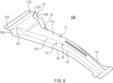
- FIG. 8 is a perspective view of a structural member according to the third embodiment.
- FIG. 9 is a plan view of a material used in press-molding the structural member shown in FIG. FIG.
- FIG. 10 is a perspective view of a mold used in the manufacturing method according to the fourth embodiment.
- FIG. 11 is a cross-sectional view of the mold shown in FIG.
- FIG. 12 is a perspective view of a mold relating to a modified example of each of the above embodiments.
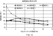
- FIG. 13 is a graph obtained by analysis, which shows the relationship between the distance from the end on the top plate side and the plate thickness reduction rate for the end edge of a vertical wall included in a structural member.
- FIG. 14 is a schematic diagram for explaining the analysis conditions.
- the manufacturing method according to the embodiment is a method for manufacturing structural components for automobiles.
- This manufacturing method includes a heating step in which a material made of a metal plate is heated, and a molding step in which the heated material is molded into a structural component using a mold.
- the mold includes a lower mold, a pad, and an upper mold.
- the lower mold includes a top surface, a shoulder portion, a side surface, and a flange surface.
- the top surface includes a top surface body and a protruding portion.
- the protruding portion protrudes outward from the side edge of the top surface body.
- the shoulder portion is continuous with the side edge of the top surface body and the protruding portion.
- the side surface is connected to the top surface body and the protruding portion via the shoulder portion.
- the flange surface is connected to the side surface on the opposite side of the top surface.
- the pad faces the top surface body.
- the upper mold is positioned to the side of the pad. In the molding process, the material is clamped between the top surface body and the pad, while the upper and lower dies are brought relatively close to each other without the material being clamped between the protruding portion, the upper die, and the pad, and the material is pressed between the upper die, the shoulder, the side, and the flange surface (first configuration).
- a structural member is formed from a material using a mold including an upper mold, a lower mold, and a pad.
- the top surface of the lower mold is provided with a top surface main body and a protruding portion that protrudes outward from the top surface main body.
- the material is sandwiched between the top surface main body of the lower mold and the pad, while the heated material is pressed by the upper and lower molds in a state in which the material is not sandwiched between the protruding portion of the top surface of the lower mold and the pad.
- the part of the material that corresponds to the protruding portion of the top surface of the lower mold in other words, the part that is molded into the protruding portion of the top plate of the structural member, is not restrained by the mold.
- the material flows from the part that will become the protruding portion of the top plate toward the part that will become the vertical wall (the part that is molded along the side of the lower mold).
- the lower die may include a first lower die and a second lower die.
- the second lower die is disposed adjacent to the first lower die.
- the second lower die includes a protruding portion on its top surface.
- the lower mold includes a first mold and a second mold separate from the first mold. Since a step is already created between the first mold and the second mold, when the structural member is molded, the first mold comes into contact with the material before the second mold including the protruding portion on the top surface. In this case, the portion of the material that corresponds to the protruding portion on the top surface of the lower mold, i.e., the portion that is molded into the protruding portion of the top plate of the structural member and its vicinity, is less likely to be restrained, and the flow of material from the top plate side to the vertical wall side can be further promoted. As a result, the occurrence of cracks can be further suppressed at the edges of the portions of the vertical walls that extend in the height direction and at the connection portions between the vertical walls and the flanges.
- the first lower die may be configured to be able to rise and fall using a cushion mechanism. In this case, during the molding process, the upper die can be lowered toward the first lower die and the second lower die (third configuration).
- the structural member according to the embodiment is a structural member for an automobile.
- the structural member includes a top plate, a ridge portion, a vertical wall, and a flange.
- the top plate includes a top plate main body and a protruding portion.
- the protruding portion protrudes outward from a side edge of the top plate main body.
- the ridge portion is continuous with the side edge of the top plate main body and the protruding portion.
- the vertical wall is connected to the top plate main body and the protruding portion via the ridge portion.
- the flange is connected to the vertical wall on the opposite side of the top plate. The flange protrudes from the vertical wall to the outside of the structural member.
- the length of the region having the plate thickness reduction rate T that satisfies the following formula at the edge of the vertical wall that is continuous with the protruding portion is 2.0 times or more the plate thickness of the top plate main body (fourth configuration).
- Tmax [%] is the maximum value of the plate thickness reduction rate at the edge of the portion of the vertical wall that is continuous with the protruding portion.
- the length of the region that satisfies the above formula is 2.0 times or more the thickness of the tabletop body.
- the thickness distribution of the portion of the vertical wall that is continuous with the protruding portion of the tabletop in other words, the edge of the portion of the vertical wall that extends in the height direction of the structural member, is relatively uniform.
- the structural member when the structural member is in use, stress is less likely to concentrate in the portion of reduced thickness at the edge of the vertical wall, and cracks can be suppressed from occurring at the edge of the vertical wall.
- the structural member can have excellent durability.
- the arithmetic mean roughness Ra of the edge of the portion of the vertical wall that is continuous with the protruding portion may be 3.00 ⁇ m or less (fifth configuration).
- the structural member may have a Vickers hardness of 325 Hv or more (sixth configuration).
- Fig. 1 is a perspective view of a structural member 10 according to a first embodiment.
- Fig. 2 is a cross-sectional view (II-II cross-sectional view) of the structural member 10.
- the structural member 10 is used as a structural member for an automobile.
- the structural member 10 is, for example, a cross member disposed on or behind a floor panel, or a cross extension provided at an end of a cross member.
- the structural member 10 includes a top plate 11, two ridges 12, two vertical walls 13, and two flanges 14.
- the tabletop 11 includes a tabletop body 111 and two protruding portions 112.
- the tabletop body 111 has an elongated shape in a plan view of the structural member 10.
- the direction in which the tabletop body 111 extends is referred to as the longitudinal direction of the structural member 10
- the direction substantially perpendicular to the longitudinal direction in a plan view of the structural member 10 is referred to as the width direction of the structural member 10.
- the direction substantially perpendicular to the longitudinal direction and width direction is referred to as the height direction of the structural member 10.
- the tabletop body 111 includes two side edges 111a. Each of the side edges 111a extends in the longitudinal direction of the structural member 10. A protrusion 112 is provided adjacent to each of the side edges 111a.
- the protruding portion 112 protrudes outward from the side edge 111a of the tabletop body 111 in the width direction of the structural member 10.
- the protruding portion 112 is provided at one end of the tabletop body 111 in the longitudinal direction.
- the tabletop 11 includes the tabletop body 111 and the two protruding portions 112, and thus has a substantially T-shape in a plan view of the structural member 10.
- the protruding portion 112 is, for example, located substantially or approximately on the same plane as the tabletop body 111.
- the ridges 12 are each continuous with the side edge 111a of the tabletop body 111. Each ridge 12 is also continuous with the overhang 112 of the tabletop 11. Each ridge 12 extends from the tabletop body 111 to the overhang 112. Each ridge 12 has a corner 121 between a portion corresponding mainly to the tabletop body 111 and a portion corresponding to the overhang 112. In a plan view of the structural member 10, the corner 121 has a radius of curvature of, for example, 5.0 mm or more and 100.0 mm or less.
- each ridge 12 has, for example, a substantially arc shape in a cross-sectional view of the structural member 10.
- each of the vertical walls 13 includes a first portion 131 and a second portion 132.
- the first portion 131 is connected to the side edge 111a of the tabletop body 111 via the ridge portion 12.
- the first portion 131 extends in the longitudinal direction of the structural member 10 along the tabletop body 111.
- the first portion 131 of one vertical wall 13 faces the first portion 131 of the other vertical wall 13 in the width direction of the structural member 10.
- the second portion 132 is connected to the overhang portion 112 of the tabletop 11 via the ridge portion 12.
- the second portion 132 extends in the height direction of the structural member 10 from the overhang portion 112 of the tabletop 11 to the flange 14.
- each flange 14 is connected to the vertical wall 13 on the opposite side of the top plate 11.
- Each flange 14 is connected to the vertical wall 13 via a ridge portion 15.
- Each ridge portion 15 extends along the first portion 131 and the second portion 132 of the vertical wall 13.
- Each ridge portion 15 has, for example, a substantially arc shape when viewed in cross section of the structural member 10.
- Each flange 14 protrudes from the vertical wall 13 to the outside of the structural member 10. More specifically, each flange 14 protrudes from the first portion 131 of the vertical wall 13 to the outside in the width direction of the structural member 10. Each flange 14 extends in the longitudinal direction of the structural member 10 along the first portion 131 of the vertical wall 13 and is connected to the second portion 132 of the vertical wall 13.
- FIGS. 3A to 3H are schematic diagrams for explaining the method for manufacturing the structural member 10.
- the method for manufacturing the structural member 10 includes a step of preparing a material M, a step of heating the material M, and a step of forming the heated material M into the structural member 10.
- the structural member 10 is manufactured by hot forming (hot stamping).
- a material M made of a metal plate is prepared.
- the material M may be made of a steel plate.
- the material M is, for example, a blank having a shape obtained by developing the structural member 10 (FIGS. 1 and 2). Such a blank can be formed by punching a metal strip (coil) using a die having a desired shape. Alternatively, the blank may be formed by hollowing out the coil using a laser.
- the heating step is a step of heating the prepared material M.
- the material M is heated to a temperature suitable for hot stamping.
- the material M is heated by, for example, a known heating furnace.
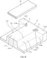
- FIG. 3B is a perspective view of the mold 20.
- Figure 3C is a horizontal cross-sectional view (IIIC-IIIC cross-sectional view) of the mold 20.
- Figure 3D is a vertical cross-sectional view (IIID-IIID cross-sectional view) of the mold 20.
- the mold 20 includes a lower mold 21, two upper molds 22, and a pad 23.
- the lower mold 21 is a punch
- the upper mold 22 is a die that corresponds to the lower mold 21.
- the lower mold 21 is positioned opposite the upper mold 22 and the pad 23.
- the lower mold 21 is positioned, for example, below the upper mold 22 and the pad 23.
- the lower mold 21, the upper mold 22, and the pad 23 are attached, for example, to a known press machine (not shown).
- the lower mold 21 includes a top surface 211, two shoulders 212, two side surfaces 213, and two flange surfaces 214.
- the top surface 211 is an upward surface facing the pad 23.
- the top surface 211 is a surface for forming the top plate 11 (FIGS. 1 and 2) of the structural member 10. Therefore, the top surface 211 has a shape corresponding to the top plate 11.
- the top surface 211 corresponds to the top plate 11, and has a substantial T-shape when viewed from above of the lower mold 21.
- the top surface 211 includes a top surface main body 211A and two protruding portions 211B.
- the top surface main body 211A has an elongated shape in a planar view of the lower mold 21, corresponding to the top plate main body 111 (FIGS. 1 and 2) of the structural member 10.
- the direction in which the top surface main body 211A extends is referred to as the longitudinal direction of the mold 20, and the direction substantially perpendicular to the longitudinal direction in a planar view of the mold 20 is referred to as the width direction of the mold 20.
- the direction substantially perpendicular to the longitudinal direction and width direction is referred to as the height direction of the mold 20.
- the longitudinal direction, width direction, and height direction of the mold 20 respectively coincide with the longitudinal direction, width direction, and height direction of the structural member 10.
- the top surface body 211A includes two side edges 211a. These side edges 211a are side edges that extend in the longitudinal direction of the top surface body 211A. Each of the side edges 211a has an adjacent protrusion 211B.
- the protruding portions 211B correspond to the protruding portions 112 (FIGS. 1 and 2) of the top plate 11 of the structural member 10, and protrude outward from the side edge 211a of the top surface body 211A.
- the protruding portions 211B are provided at one end of the top surface body 211A in the longitudinal direction.
- the protruding portions 211B are, for example, located substantially or approximately on the same plane as the top surface body 211A.
- Each of the shoulders 212 is continuous with the side edge 211a of the top surface body 211A. Each shoulder 212 is also continuous with the overhang 211B of the top surface 211. Each shoulder 212 corresponds to the ridge portion 12 (FIGS. 1 and 2) of the structural member 10, and extends from the top surface body 211A to the overhang 211B.
- the side surface 213 corresponds to the first portion 131 and the second portion 132 ( Figures 1 and 2) of the vertical wall 13 of the structural member 10, and includes a first portion 213A and a second portion 213B.
- the first portion 213A is connected to the side edge 211a of the top surface main body 211A via a shoulder portion 212, and extends in the longitudinal direction of the mold 20.
- the second portion 213B is connected to the overhang portion 211B of the top surface 211 via a shoulder portion 212.
- the second portion 213B extends in the height direction of the lower mold 21 from the overhang portion 211B of the top surface 211 to the flange surface 214.
- the flange surfaces 214 are each connected to the side surface 213 on the opposite side to the top surface 211.
- Each flange surface 214 corresponds to the flange 14 of the structural member 10 and protrudes from the side surface 213 to the outside of the lower mold 21. More specifically, each flange surface 214 protrudes outward from the first portion 213A of the side surface 213 in the width direction of the mold 20.
- Each flange surface 214 extends in the longitudinal direction of the mold 20 along the first portion 213A of the side surface 213 and is connected to the second portion 213B of the side surface 213.
- the two upper dies 22 are attached to a slide that can be raised and lowered in, for example, a press machine (not shown).
- Each of the upper dies 22 includes a molding surface 221.
- the molding surface 221 has a shape corresponding to the shoulder 212, side surface 213, and flange surface 214 of the lower die 21.
- a pad 23 is disposed between the two upper dies 22. That is, the upper dies 22 are disposed on both sides of the pad 23.
- These upper dies 22 may be separate bodies, or may be formed integrally.
- the pad 23 is connected to the slide of a press (not shown), for example, via an expandable elastic member 24.
- the pad 23 faces the top surface main body 211A of the lower die 21.
- the pad 23 does not face the protruding portion 211B of the top surface 211 of the lower die 21.
- the pad 23 is positioned further inward in the width direction of the die 20 than the portion of the shoulder portion 212 of the lower die 21 that is continuous with the protruding portion 211B.
- the pad 23 has, for example, a substantially I-shape when the die 20 is viewed in plan.
- the mold 20 configured in this manner is used to mold the material M into the structural member 10 (Figs. 1 and 2).
- the material M is sandwiched between the top surface body 211A of the lower mold 21 and the pad 23, while the material M is not substantially sandwiched between the protrusion 211B on the top surface 211 of the lower mold 21 and the upper mold 22 and pad 23.
- the upper mold 22 and the lower mold 21 are brought relatively close to each other, and the material M is pressed between the upper mold 22 and the shoulder portion 212, side surface 213, and flange surface 214 of the lower mold 21.
- the molding process will be described in more detail below.
- the upper die 22 and pad 23 attached to the slide of the press machine (not shown) are positioned at the top dead center.
- the material M heated in the heating process is placed on the top surface 211 of the lower die 21.
- the upper die 22 and pad 23 are lowered toward the lower die 21 together with the slide of the press machine, and the upper die 22 and pad 23 are brought closer to the lower die 21.
- the material M on the lower die 21 is pressed down by the pad 23, as shown in FIG. 3E. More specifically, the portion of the material M located on the top surface main body 211A of the lower die 21 is clamped between the lower die 21 and the pad 23. On the other hand, the portion of the material M located on the protruding portion 211B of the top surface 211 of the lower die 21 is not clamped between the lower die 21 and the pad 23.
- each shoulder 212 has a corner portion 212A between the portion corresponding mainly to the top surface main body 211A and the portion corresponding to the protruding portion 211B.
- the lower mold 21 includes an area A adjacent to the corner portion 212A when viewed along the pressing direction. As shown by hatching in FIG. 3F, the area A is an area from the corner portion 212A to the inside of the top surface 211 up to 10 times the plate thickness of the material M (FIG. 3E).
- the pad 23 is arranged so as to overlap at least a part of the area A when viewed along the pressing direction (height direction). That is, at least a part of the range of the material M that faces the area A adjacent to the corner portion 212A in the pressing direction is pressed by the pad 23. On the other hand, the portion of the material M that is located outside the area A adjacent to the corner portion 212A in the width direction of the lower mold 21 is not pressed by the pad 23. That is, during the molding process, the pad 23 does not restrain the portion of the material M that is located outside in the width direction from the end of the corner portion 212A on the protruding portion 211B side.
- the upper die 22 when the upper die 22 reaches the bottom dead center, the upper die 22 and the lower die 21 completely press the material M, forming the structural member 10.
- the structural member 10 is heat-removed (hardened) by contact with the die 20, and its strength is increased.
- the edge 132a of the second portion 132 of each vertical wall 13 includes a deformation region R1.
- the deformation region R1 is within the range from the R end (vertical wall 13 side) of the edge 12a of the ridge portion 12 that connects the edge 112a of the protruding portion 112 of the top plate 11 and the edge 132a of the second portion 132 of the vertical wall 13 to the R end (vertical wall 13 side) of the edge 15a of the ridge portion 15 that connects the edge 132a of the second portion 132 of the vertical wall 13 and the edge 14a of the flange 14.
- the deformation region R1 has a plate thickness reduction rate T [%] that satisfies the following formula (1) throughout its entirety. 0.9 ⁇ Tmax ⁇ T ⁇ Tmax (1)
- Tmax [%] in the above formula (1) is the maximum value of the plate thickness reduction rate T at the edge 132a of the second portion 132 of each vertical wall 13.
- the plate thickness reduction rate T is a plate thickness reduction rate based on the plate thickness of the tabletop body 111.
- the plate thickness reduction rate T [%] at that position can be obtained by (t0-t1)/t0 ⁇ 100.
- the plate thickness t0 of the tabletop body 111 is the plate thickness of a portion of the tabletop body 111 where distortion due to molding has not substantially occurred.
- the plate thickness t0 is substantially equal to the plate thickness of the material M before molding.
- the plate thickness t0 is measured in the central portion of the tabletop body 111 and in a portion having a flat shape.
- Plate thickness t0 is, for example, the plate thickness of the tabletop body 111 measured at a position 5 mm or more away from the ridge line portion 12 or the longitudinal end of the tabletop body 111.
- the plate thickness of the tabletop body 111 measured at a position 5 mm or more away from not only the ridge line portion 12 and the longitudinal end of the tabletop body 111, but also the step, the protrusion, and the through hole is defined as plate thickness t0.
- the length of the deformation region R1 is 2.0 times or more the thickness t0 of the tabletop body 111.
- the length of the deformation region R1 is preferably 2.5 times or more the thickness t0 of the tabletop body 111.
- the length of the deformation region R1 may be 6.0 times or less the thickness t0 of the tabletop body 111.
- the structural member 10 can have a Vickers hardness of 325 Hv or more.
- the Vickers hardness HV of the structural member 10 can be evaluated by the Vickers hardness of the top plate 11.
- a commercially available measuring device (fully automatic Vickers hardness tester HV-100, manufactured by Mitutoyo Corporation) is used to perform a Vickers hardness test in accordance with JIS Z 2244:2009 to measure the Vickers hardness [Hv] at any five points on the top plate 11.
- the average value of the Vickers hardness at these five points can be regarded as the Vickers hardness HV of the structural member 10.
- the Vickers hardness of the top plate 11 is measured, for example, with a test force of 294.2 N (the value of HV30) and a holding time of the test force of 15 seconds.
- the structural member 10 is molded from the material M using a mold 20 including a lower mold 21, an upper mold 22, and a pad 23.
- the portion of the material M located at the top surface main body 211A of the lower mold 21 is pressed by the pad 23, while the portion of the material M located at the protruding portion 211B of the lower mold 21 is not pressed by the pad 23.
- the portion of the material M located at the protruding portion 211B of the lower mold 21, that is, the portion that will become the protruding portion 112 of the top plate 11 of the structural member 10 is not restrained by the mold 20.
- the portion of the material M that will become the protruding portion 112 of the top plate 11 is separated from the mold 20 during molding. Therefore, during the molding process, the protruding portion 112 of the top plate 11 is less likely to be cooled, and the material can flow in the protruding portion 112.
- the material flows from the overhanging portion 112 of the top plate 11 toward the second portion 132 of the vertical wall 13 in the height direction of the structural member 10. This makes it possible to suppress the occurrence of cracks in the structural member 10.
- a blank material with excess padding is used as a countermeasure to alleviate the shape outside the product and manufacture the molded product.
- the overhanging portion 112 of the top plate 11 is not restrained by the mold 20, so that it is possible to suppress the occurrence of cracks at the edge of the vertical wall 13 during the molding process. Therefore, the trimming process after the molding process is unnecessary.
- the trimming process is unnecessary, the amount of material M input to the molding process can be reduced compared to when the trimming process is performed.
- the yield rate in the manufacture of the structural member 10 can be improved.
- the amount of material M input is reduced and the trimming process is not performed, which reduces the amount of transportation and electricity required in the manufacture of the structural member 10, and therefore the amount of greenhouse gas emissions can also be reduced.
- the edges of the completed structural member 10 are smoother than the edges of structural members that have been through a trimming process in which laser cutting is performed.
- the arithmetic mean roughness Ra of the edge portion (laser cut surface) created by laser cutting was measured, and the minimum arithmetic mean roughness Ra of the laser cut surface was 4.20 ⁇ m.
- the arithmetic mean roughness Ra of the edge portion (laser cut surface) created by laser cutting of other automotive parts was measured, the arithmetic mean roughness Ra of the laser cut surface exceeded 3.00 ⁇ m.
- the edge 132a of the second portion 132 of the vertical wall 13 and the edge 12a of the ridge portion 12 connecting the vertical wall 13 to the top plate 11 are not laser cut. Therefore, the arithmetic mean roughness Ra of the edges 132a, 12a is significantly smaller than the arithmetic mean roughness Ra of the surface laser cut after the molding process. More specifically, in the structural member 10, the arithmetic mean roughness Ra of the edge 132a of the second portion 132 of the vertical wall 13 is 3.00 ⁇ m or less. Similarly, the arithmetic mean roughness Ra of the edge 12a of the ridge portion 12 is 3.00 ⁇ m or less.
- the arithmetic mean roughness Ra at the edge 132a of the second portion 132 of the vertical wall 13 and the edge 12a of the ridge portion 12 can be measured using a commercially available surface roughness measuring device. More specifically, using a surface roughness measuring device (laser microscope, manufactured by Keyence Corporation), in accordance with JIS B 0601:2013, a roughness curve is created at a position 0.1 mm from the plate surface in the region (thick line region in FIG. 5) consisting of the edge 132a of the vertical wall 13 and the edge 12a of the ridge portion 12, and the arithmetic mean roughness Ra can be obtained with an evaluation length of the roughness curve of 12.5 mm and a reference length of 2.5 mm.
- a surface roughness measuring device laser microscope, manufactured by Keyence Corporation
- a roughness curve is created at a position 0.1 mm from the center of the plate thickness and the back surface of the plate in the region formed by the edge 132a of the vertical wall 13 and the edge 12a of the ridge portion 12, and the arithmetic mean roughness Ra can be obtained with an evaluation length of the roughness curve of 12.5 mm and a reference length of 2.5 mm.
- the obtained arithmetic mean roughness Ra is 3.00 ⁇ m or less in all cases.
- the second portion 132 of the vertical wall 13 has a deformation region R1 at the edge 132a that satisfies the above formula (1).
- the length of the deformation region R1 is 2.0 times or more the thickness t0 of the tabletop body 111. This means that the thickness distribution at the edge 132a of the second portion 132 in each vertical wall 13 is uniform. In this case, when the structural member 10 is in use, stress concentration at the reduced thickness portion at the edge 132a of the second portion 132 of each vertical wall 13 is less likely to occur, and cracks can be suppressed at the edge 132a. In other words, the structural member 10 can have excellent durability.
- the manufacturing method according to this embodiment can suppress the occurrence of cracks in the second portion 132 of the vertical wall 13 and its vicinity when the material M is formed into the structural member 10. Therefore, a high-strength material can be used as the material for the structural member 10.
- the structural member 10 can be made of a steel plate having a tensile strength of 1000 MPa or more or 2000 MPa or more after hot stamping. By making the structural member 10 out of a high-strength material, the structural member 10 can be made thinner and lighter while still maintaining the strength of the structural member 10.
- structural members formed by hot stamping are hard in areas where no thickness reduction occurred during forming, and are insufficient in hardness in areas where thickness reduction occurred. For this reason, in the case of general structural members, deformation is concentrated in the areas where thickness reduction occurred, and cracks may occur depending on the degree of deformation concentration.
- the thickness distribution is made uniform as described above. That is, in the case of the structural member 10, thickness reduction is dispersed, and localized reductions in hardness are suppressed. Therefore, it is possible to reduce deformation concentration during use of the structural member 10, and to improve the durability of the structural member 10.
- the radius of curvature of the corner portion 121 of the ridge portion 12 is, for example, 100.0 mm or less, preferably 50.0 mm or less, and more preferably 25.0 mm or less.
- the intersection angle between the first part 131 and the second part 132 of the vertical wall 13 continuing to the ridge portion 12 can be, for example, approximately a right angle. This allows the structural member 10 to have excellent space efficiency. In other words, the degree of freedom of spatial arrangement with other parts can be increased, and the dimensional constraints on the design of the structural member 10 or other parts can be reduced.
- the load transmission ability of the structural member 10 can be ensured. Specifically, when a longitudinal load is input to the structural member 10 arranged in a narrow area, the second part 132 of the vertical wall 13 can receive the load on its surface, and the load is easily transmitted from the second part 132 to other parts. As a result, the structural member 10 can exhibit good transmission capabilities for loads in the longitudinal direction.
- Second Embodiment 6 is a perspective view of a structural member 10A according to the second embodiment.
- the basic configuration of the structural member 10A according to this embodiment is the same as that of the structural member 10 according to the first embodiment.
- the structural member 10A differs from the structural member 10 according to the first embodiment in the shape of the top plate 11.
- a portion of the tabletop body 111 is raised upward compared to other portions.
- the height of the vertical wall 13 varies in parts depending on the shape of the tabletop body 111.
- the structural member 10A according to this embodiment can also be manufactured by the manufacturing method described in the first embodiment.
- a preforming process may be performed before the molding process to form an intermediate molded product from a metal plate (blank).
- the intermediate molded product is formed from the metal plate, for example, by drawing.
- the intermediate molded product may be, for example, one in which a protruding portion of the top plate main body 111 is formed.
- the intermediate molded product may be one in which the shape of the protruding portion 112 of the top plate 11 and the second portion 132 of the vertical wall 13 is gently given.
- the preforming process is typically performed in a cold state. In this case, the intermediate molded product obtained in the preforming process is heated, and the heated intermediate molded product is used as a material for the molding process.
- the structural member 10A may have a notch 16, for example, at the connection between the second portion 132 of the vertical wall 13 and the flange 14.
- the notch 16 may be provided on only one side in the width direction of the structural member 10A, or on both sides in the width direction.
- the notch 16 may be formed in advance in the material before it is molded into the structural member 10A.
- the structural member 10 (FIGS. 1 and 2) according to the first embodiment may also have a notch 16.
- the structural members 10, 10A do not have notches.
- the edges of the protrusions 112 of the top plate 11, the vertical walls 13, and the flanges 14 are smoothly continuous.
- the load transmission ability of the structural members 10, 10A during a car collision can be improved.
- water can be prevented from entering the structural members 10, 10A through the notches, and rusting of the structural members 10, 10A can be suppressed.
- Third Embodiment 8 is a perspective view of a structural member 10B according to the third embodiment.
- the structural member 10B according to this embodiment has a different shape from the structural members 10 and 10A according to the above embodiments.
- the structural members 10 and 10A according to the above embodiments can be used, for example, as a cross member disposed on or behind a floor panel, or a cross extension provided at the end of a cross member.
- the structural member 10B according to this embodiment can be used, for example, as a B-pillar.
- structural member 10B like structural members 10 and 10A according to the above-described embodiments, has a top plate 11 including a top plate main body 111 and a protruding portion 112. Also, like structural members 10 and 10A, structural member 10B has a vertical wall 13 including a first portion 131 and a second portion 132. In structural member 10B, the first portion 131 and the second portion 132 of vertical wall 13 are connected to top plate 11 and flange 14 via ridge portions 12 and 15. Flange 14 is provided on the opposite side of top plate 11 from first portion 131 and second portion 132 of vertical wall 13.
- the structural member 10B according to this embodiment can also be manufactured by the manufacturing method described in the first embodiment.
- a blank having the shape of the structural member 10B unfolded can be prepared as the material M, as shown in FIG. 9.
- the blank can be formed by punching a metal strip (coil) using a die, or by hollowing out the metal strip using a laser.
- the structural member 10B is manufactured by the manufacturing method described in the first embodiment, like the structural members 10 and 10A according to the above embodiments, cracks are unlikely to occur at the edges of the vertical walls 13 during the molding process. Therefore, a trimming process after the molding process is not required for the structural member 10B either. In other words, after the molding process, there is no need to laser cut the outer periphery of the structural member 10B. Therefore, like the structural members 10 and 10A according to the above embodiments, the arithmetic mean roughness Ra of the edges of the second portions 132 of the vertical walls 13 and the edges of the ridge portions 12 of the structural member 10B is 3.00 ⁇ m or less.
- the edge of the second portion 132 of each vertical wall 13 can have a deformation region R1 similar to the structural members 10 and 10A according to the above embodiment.
- the structural member 10B can have a Vickers hardness of 325 Hv or more, similar to the structural members 10 and 10A according to the above embodiment.
- the ridge portion 12 includes a corner portion 121, similar to the structural members 10 and 10A according to the above embodiments.
- the radius of curvature of the corner portion 121 is, for example, 20.0 mm or more and 300.0 mm or less.
- the radius of curvature of the corner portion 121 is preferably 15.0 mm or more and 200.0 mm or less, and more preferably 15.0 mm or more and 100.0 mm or less.
- the intersection angle between the first portion 131 and the second portion 132 of the vertical wall 13 continuing to the ridge portion 12 can be set to a right angle or an angle close to a right angle, so that the structural member 10B can be arranged in a narrow area. Therefore, the dimensions of the structural member 10B are less restricted by the spatial arrangement relationship with other parts.
- the second portion 132 of the vertical wall 13 can receive the load on its surface, allowing the structural member 10B to exhibit good transmission capabilities for the longitudinal load.
- Fig. 10 is a perspective view of a mold 20A used in the manufacturing method according to this embodiment.
- Fig. 11 is a cross-sectional view (XI-XI cross-sectional view) of the mold 20A.
- the mold 20A differs from the mold 20 described in the first embodiment only in the configuration of the lower mold 21.
- the structural members 10, 10A, and 10B according to the above embodiments can also be molded using the mold 20A.
- the lower die 21 includes a first lower die 215 and a second lower die 216.
- the first lower die 215 and the second lower die 216 are separate bodies and can operate independently.
- the second lower die 216 includes a protruding portion 211B of the top surface 211.
- the second lower die 216 also includes a second portion 213B of the side surface 213.
- the second lower die 216 is disposed adjacent to the first lower die 215.
- the first lower die 215 is configured to be able to rise and fall by a cushion mechanism 25.
- the cushion mechanism 25 may be one that is commonly used in known press machines (not shown), and may include, for example, a die cushion, a cushion pin, etc.
- the operation of the mold 20A is the same as that of the mold 20 in the above embodiment.
- a step is already created between the first lower die 215 and the second lower die 216.
- the first lower die 215 is supported by a cushion mechanism 25 and is positioned slightly above the second lower die 216 before the start of the molding process. Therefore, when the upper die 22 is lowered toward the first lower die 215 and the second lower die 216, the first lower die 215 presses the material M between the upper die 22 and the second lower die 216 before the second lower die 216. At the point when the material M is pressed by the upper die 22 and the first lower die 215, the second lower die 216 does not press the material M.
- the upper die 22 which is holding the material M together with the first lower die 215, is brought closer to the second lower die 216, the upper die 22 presses down the first lower die 215, which is supported by the cushion mechanism 25. This gradually reduces the step between the first lower die 215 and the second lower die 216.
- the step between the first lower die 215 and the second lower die 216 disappears, and the material M is pressed not only between the first lower die 215, but also between the second lower die 216 and the upper die 22.
- a step is created in advance between the first lower die 215 and the second lower die 216, so when forming the structural members 10, 10A, and 10B according to the above embodiment, the first lower die 215 comes into contact with the material M before the second lower die 216 including the protruding portion 211B of the top surface 211.
- the portion of the material M corresponding to the protruding portion 211B of the top surface 211 of the lower die 21, i.e., the portion that becomes the protruding portion 112 of the top plate 11 of the structural members 10, 10A, and 10B, and its vicinity, are less likely to be constrained, and the flow of material from the protruding portion 112 of the top plate 11 to the second portion 132 of the vertical wall 13 can be further promoted. Therefore, the occurrence of cracks at the edge of the second portion 132 extending in the height direction of the vertical wall 13 and at the connection portion between the vertical wall 13 and the flange 14 can be further suppressed.
- the protrusion 112 of the top plate 11 is provided only at one longitudinal end of the structural members 10, 10A, and 10B.
- the protrusion 112 may be provided at both longitudinal ends of the structural members 10, 10A, and 10B. In this case, too, the structural members 10, 10A, and 10B are hot stamped without pressing the protrusions 112 with the pads 23.
- the structural members 10, 10A, and 10B can be divided into two after the molding process. This makes it possible to manufacture two structural members 10, 10A, or 10B that have a protruding portion 112 at only one longitudinal end in a single molding process.
- the upper die 22 is positioned above the lower die 21. Furthermore, when molding the material M into the structural members 10, 10A, 10B, the upper die 22 and the lower die 21 are brought closer together by moving the upper die 22 toward the lower die 21. However, contrary to the above embodiment, the upper die 22 may be positioned below the lower die 21. Furthermore, the lower die 21 may be moved toward the upper die 22 to bring the upper die 22 relatively closer to the lower die 21.
- the length (width) of the pad 23 in the width direction of the mold 20 or mold 20A is substantially constant.
- the width of the pad 23 does not necessarily have to be constant throughout.
- the width of the pad 23 may be wider on the side of the protruding portion 211B of the lower mold 21.
- the pad 23 is configured not to press the material outside in the width direction of the region A adjacent to the corner portion 212A of the lower mold 21.
- examples with no cushion setting are obtained by molding a structural member 10 (FIGS. 1 and 2) using the mold 20 of the first embodiment (FIGS. 3B to 3G).
- examples with a cushion setting are obtained by molding a structural member 10 (FIGS. 1 and 2) using the mold 20A of the fourth embodiment (FIGS. 10 and 11).
- the cushion stroke (cushion St.) is the distance the first lower die 215 is lowered by the cushion mechanism 25, and is equal to the size of the step between the first lower die 215 and the second lower die 216.
- the comparative example is obtained by molding a structural member 10 using a mold that differs from the mold 20 only in the shape of the pad.
- the pad 23 in the mold 20 has an I-shape in plan view and is configured not to press the protruding portion 112 of the top plate 11 of the structural member 10, whereas the pad used in the comparative example has a T-shape in plan view and is configured to press almost the entire surface of the top plate 11. That is, in the comparative example, the structural member 10 is formed with the top plate body 111 and the protruding portion 112 held down by pads.
- the maximum thickness reduction rate of the edge 132a of the second portion 132 of the vertical wall 13 is significantly smaller than in Comparative Examples 1 to 4.
- the maximum thickness reduction rate of Examples 1 to 11 was less than 20%.
- the length of the deformation region R1 that satisfies the above formula (1) was ensured to be 2.0 times or more the thickness t of the material.
- Figure 13 is a graph showing the relationship between the distance from the R end on the edge 12a side of the ridgeline portion 12 and the sheet thickness reduction rate T at the edge 132a of the second portion 132 of the vertical wall 13.
- the change in the sheet thickness reduction rate T is more gradual in Examples 1 to 4 than in Comparative Example 1.
- Figure 13 shows that the maximum sheet thickness reduction rate in Examples 1 to 4 is significantly smaller than the maximum sheet thickness reduction rate in Comparative Example 1. That is, it can be seen that in Examples 1 to 4, the sheet thickness reduction at the edge 132a of the second portion 132 of the vertical wall 13 is suppressed, and the sheet thickness distribution at the edge 132a is made uniform.
- the Vickers hardness HV of the structural member 10 was measured for each of the examples and comparative examples by the method described in the first embodiment above.
- the Vickers hardness HV was determined as the average value of the Vickers hardness [Hv] obtained by measuring five points at a position 5 mm inward from the edge of the protruding portion 112 side of the top plate 11, the center point in the width direction, points 5 mm from both ends in the width direction, and their midpoints.
- the structural member 10 was formed by hot stamping, so the Vickers hardness of the structural member 10 was 325 Hv or more in both the examples and comparative examples.
- the Vickers hardness was measured for the part where the plate thickness reduction rate was maximum (the part with the maximum plate thickness reduction) and the part where no plate thickness reduction occurred (the normal part) for each of Example 1 and Comparative Example 1.
- the Vickers hardness of the part with the maximum plate thickness reduction was 360 Hv
- the Vickers hardness of the normal part was 410 Hv.
- the Vickers hardness of the part with the maximum plate thickness reduction was 306 Hv
- the Vickers hardness of the normal part was 414 Hv. From this result, it can be said that when the structural member 10 is formed by the manufacturing method according to the present disclosure, the local decrease in hardness is suppressed by dispersing the plate thickness reduction. Therefore, it is expected that the effect of suppressing the concentration of deformation when the structural member 10 is deformed due to a collision is suppressed. Therefore, it is assumed that the structural member 10 formed by the manufacturing method according to the present disclosure has excellent collision resistance.
- the yield was calculated by dividing the weight (kg) of the structural member 10 by the weight (kg) of the metal strip (coil) before cutting out the blank as the material for press forming.
- a CAE analysis similar to that described above was carried out for the case where the structural member 10 was formed by drawing using a die including a punch, a die, and a blank holder, and the yield was calculated.
- Example 5 greenhouse gas emissions (CO 2 -eq) during the manufacture of the structural member 10 were calculated using a part LCA (Life Cycle Assessment) tool (a tool capable of analyzing life cycle greenhouse gas emissions proposed by the Automotive Subcommittee of the World Steel Association (WAS), an Excel-format analysis software downloaded from the WAS website (https://www.worldautosteel.org/life-cycle-thinking/case-studies/comparing-material-usage-in-production-vehicle-efficient-designs/)). The calculation results are shown in Table 2 .
- LCA Life Cycle Assessment
- WAS World Steel Association
- Example 5 in which pad bending was performed using a die 20 including an I-shaped pad 23 in a plan view, a high yield was ensured.
- no excess material is required on the blank to be gripped by the blank holder and die, and no cracks occur in the structural member 10, so there is no need to perform laser cutting after pad bending. Therefore, the blank cut from the coil can be made into the expanded shape of the structural member 10, and the dimensions of the coil can be made smaller than in the reference example.
- the weight of the blank and coil is smaller than the weight of the structural member 10, and the yield was high at 82%.
- Example 5 the weight of the coil is smaller than in the reference example, and laser cutting is not required. Therefore, in Example 5, the amount of greenhouse gas emissions during the manufacture of the structural member 10 was also reduced compared to the reference example.
- the arithmetic mean roughness Ra of the edge 132a of the vertical wall 13 was calculated by the method described in the first embodiment above.
- the arithmetic mean roughness Ra was calculated in the range of ⁇ 6.25 mm in the height direction from the center of the edge 132a of the vertical wall 13.
- the arithmetic mean roughness Ra was 1.91 ⁇ m at the minimum and 2.10 ⁇ m at the maximum.
- the arithmetic mean roughness Ra was 4.27 ⁇ m at the minimum. Therefore, it was confirmed that if laser cutting is not performed on the edge 132a of the vertical wall 13 after hot stamping, the arithmetic mean roughness Ra of the edge 132a of the vertical wall 13 is 3.00 ⁇ m or less.
- Example 12 in which a pad that is T-shaped in plan view was used and the entire surface of the tabletop 11 (tabletop body 111 and overhang 112) was pressed down with the pad to form the structural member 10B, cracks occurred in the second portion 132 of the vertical wall 13 that extends in the height direction of the structural member 10,.
- Example 12 in which a pad 23 that is I-shaped in plan view was used and the structural member 10B was formed without pressing down the overhang 112 of the tabletop 11 with the pad 23, no cracks occurred in the structural member 10B.
- Example 12 the maximum thickness reduction rate at the edge of the second portion 132 of the vertical wall 13 is significantly smaller than in Comparative Example 5, and the length of the deformation region R1 that satisfies the above formula (1) is ensured to be at least 2.0 times the thickness t of the material.
- Example 12 in which the structural member 10B is molded as in Examples 1 to 11 in which the structural member 10 is molded, it is possible to suppress the thickness reduction at the edge of the second portion 132 of the vertical wall 13, and to uniformize the thickness distribution at the edge.
- Example 12 For each of Example 12 and Comparative Example 5, the Vickers hardness HV of the structural member 10B was measured using the same method as in Example 1. In addition, for each of Example 12 and Comparative Example 5, the arithmetic mean roughness Ra of the edge 132a of the vertical wall 13 was calculated using the same method as in Example 2.
- structural member 10B was formed by hot stamping, so the Vickers hardness of structural member 10B was 325 Hv or more in both Example 12 and Comparative Example 5.
- the arithmetic mean roughness Ra of Example 12 was a minimum of 2.87 ⁇ m and did not exceed 3.00 ⁇ m at most.
- the arithmetic mean roughness Ra of Comparative Example 5 was a minimum of 6.41 ⁇ m.
- the pad 23 pressed down the material in at least a part of region A adjacent to the corner portion 212A of the shoulder portion 212 of the lower mold 21 during the molding process.
- the pad 23 did not press down the material outside region A in the width direction of the lower mold 21.
- Comparative Example 6 the pad 23 was positioned in front of region A in the longitudinal direction of the lower mold 21, and the pad 23 did not press down the material located in region A during the molding process.
- Comparative Example 7 the pad 23 was positioned outside region A in the width direction of the lower mold 21, and the pad 23 pressed down the material not only in region A but also on the width direction outside region A during the molding process.
- Example 13 the structural member 10 could be molded without cracks or wrinkles. In Examples 13 and 14, molding defects such as necking did not occur. In contrast, in Comparative Example 7, cracks occurred during molding of the structural member 10. In Comparative Example 6, no cracks or necking occurred, but wrinkles occurred in the structural member 10.
- the formability of the structural member 10 is improved by pressing the material with the pad 23 in at least a part of the region A adjacent to the corner portion 212A of the lower die 21, while not pressing the material with the pad 23 outside the region A in the width direction of the lower die 21.
- Top plate 111 Top plate main body 111a: Side edge 112: Protruding portion 112a: Edge 12: Ridge line portion 13: Vertical wall 132a: Edge 14: Flange 20, 20A: Mold 21: Lower mold 211: Top surface 211A: Top surface main body 211a: Side edge 211B: Protruding portion 212: Shoulder portion 213: Side surface 214: Flange surface 215: First lower mold 216: Second lower mold 22: Upper mold 23: Pad 25: Cushioning mechanism
Landscapes
- Engineering & Computer Science (AREA)
- Mechanical Engineering (AREA)
- Physics & Mathematics (AREA)
- Thermal Sciences (AREA)
- Chemical & Material Sciences (AREA)
- Combustion & Propulsion (AREA)
- Transportation (AREA)
- Shaping Metal By Deep-Drawing, Or The Like (AREA)
Priority Applications (4)
| Application Number | Priority Date | Filing Date | Title |
|---|---|---|---|
| CN202280101778.4A CN120187540A (zh) | 2022-11-14 | 2022-11-14 | 构造构件及其制造方法 |
| EP22965691.3A EP4620592A4 (en) | 2022-11-14 | 2022-11-14 | STRUCTURAL ELEMENT AND METHOD FOR ITS MANUFACTURE |
| JP2023513360A JP7273355B1 (ja) | 2022-11-14 | 2022-11-14 | 構造部材及びその製造方法 |
| PCT/JP2022/042159 WO2024105714A1 (ja) | 2022-11-14 | 2022-11-14 | 構造部材及びその製造方法 |
Applications Claiming Priority (1)
| Application Number | Priority Date | Filing Date | Title |
|---|---|---|---|
| PCT/JP2022/042159 WO2024105714A1 (ja) | 2022-11-14 | 2022-11-14 | 構造部材及びその製造方法 |
Publications (1)
| Publication Number | Publication Date |
|---|---|
| WO2024105714A1 true WO2024105714A1 (ja) | 2024-05-23 |
Family
ID=86321996
Family Applications (1)
| Application Number | Title | Priority Date | Filing Date |
|---|---|---|---|
| PCT/JP2022/042159 Ceased WO2024105714A1 (ja) | 2022-11-14 | 2022-11-14 | 構造部材及びその製造方法 |
Country Status (4)
| Country | Link |
|---|---|
| EP (1) | EP4620592A4 (https=) |
| JP (1) | JP7273355B1 (https=) |
| CN (1) | CN120187540A (https=) |
| WO (1) | WO2024105714A1 (https=) |
Families Citing this family (2)
| Publication number | Priority date | Publication date | Assignee | Title |
|---|---|---|---|---|
| JP7662721B2 (ja) * | 2023-08-10 | 2025-04-15 | フタバ産業株式会社 | プレス成形品の製造方法 |
| JPWO2025142410A1 (https=) * | 2023-12-28 | 2025-07-03 |
Citations (7)
| Publication number | Priority date | Publication date | Assignee | Title |
|---|---|---|---|---|
| JP2010036217A (ja) * | 2008-08-05 | 2010-02-18 | Sumitomo Metal Ind Ltd | センターピラーアウターパネルの製造方法およびセンターピラーアウターパネル用ブランク |
| JP2013035068A (ja) * | 2010-05-19 | 2013-02-21 | Nippon Steel & Sumitomo Metal Corp | L字状形状を有する部品のプレス成形方法 |
| WO2015174353A1 (ja) * | 2014-05-14 | 2015-11-19 | 新日鐵住金株式会社 | ブランク及びプレス成形品の製造方法 |
| JP5958644B2 (ja) | 2013-03-21 | 2016-08-02 | 新日鐵住金株式会社 | プレス成形部材の製造方法及びプレス成形装置 |
| JP2019013952A (ja) | 2017-07-06 | 2019-01-31 | Jfeスチール株式会社 | プレス成形方法 |
| WO2019225661A1 (ja) * | 2018-05-24 | 2019-11-28 | Jfeスチール株式会社 | プレス部品の製造方法 |
| JP2020152173A (ja) * | 2019-03-19 | 2020-09-24 | Jfeスチール株式会社 | 車体骨格部品の継手構造、車体骨格部品及び該車体骨格部品の製造方法 |
Family Cites Families (2)
| Publication number | Priority date | Publication date | Assignee | Title |
|---|---|---|---|---|
| JP7335197B2 (ja) * | 2020-04-20 | 2023-08-29 | 豊田鉄工株式会社 | 長尺形状部品のプレス成形法、及び同成形法により成形した車両用ピラー部材 |
| JP7311830B1 (ja) * | 2021-09-03 | 2023-07-20 | 日本製鉄株式会社 | 構造部材及びその製造方法 |
-
2022
- 2022-11-14 CN CN202280101778.4A patent/CN120187540A/zh active Pending
- 2022-11-14 WO PCT/JP2022/042159 patent/WO2024105714A1/ja not_active Ceased
- 2022-11-14 EP EP22965691.3A patent/EP4620592A4/en active Pending
- 2022-11-14 JP JP2023513360A patent/JP7273355B1/ja active Active
Patent Citations (8)
| Publication number | Priority date | Publication date | Assignee | Title |
|---|---|---|---|---|
| JP2010036217A (ja) * | 2008-08-05 | 2010-02-18 | Sumitomo Metal Ind Ltd | センターピラーアウターパネルの製造方法およびセンターピラーアウターパネル用ブランク |
| JP2013035068A (ja) * | 2010-05-19 | 2013-02-21 | Nippon Steel & Sumitomo Metal Corp | L字状形状を有する部品のプレス成形方法 |
| JP5958644B2 (ja) | 2013-03-21 | 2016-08-02 | 新日鐵住金株式会社 | プレス成形部材の製造方法及びプレス成形装置 |
| WO2015174353A1 (ja) * | 2014-05-14 | 2015-11-19 | 新日鐵住金株式会社 | ブランク及びプレス成形品の製造方法 |
| JP6436166B2 (ja) | 2014-05-14 | 2018-12-12 | 新日鐵住金株式会社 | ブランク及びプレス成形品の製造方法 |
| JP2019013952A (ja) | 2017-07-06 | 2019-01-31 | Jfeスチール株式会社 | プレス成形方法 |
| WO2019225661A1 (ja) * | 2018-05-24 | 2019-11-28 | Jfeスチール株式会社 | プレス部品の製造方法 |
| JP2020152173A (ja) * | 2019-03-19 | 2020-09-24 | Jfeスチール株式会社 | 車体骨格部品の継手構造、車体骨格部品及び該車体骨格部品の製造方法 |
Non-Patent Citations (1)
| Title |
|---|
| See also references of EP4620592A4 |
Also Published As
| Publication number | Publication date |
|---|---|
| JP7273355B1 (ja) | 2023-05-15 |
| EP4620592A1 (en) | 2025-09-24 |
| CN120187540A (zh) | 2025-06-20 |
| EP4620592A4 (en) | 2026-01-07 |
| JPWO2024105714A1 (https=) | 2024-05-23 |
Similar Documents
| Publication | Publication Date | Title |
|---|---|---|
| JP7311830B1 (ja) | 構造部材及びその製造方法 | |
| CN109414745B (zh) | 冲压部件的制造方法及制造装置 | |
| EP2896467B1 (en) | Method for producing curved article | |
| AU2011255898B2 (en) | Method for press-forming l-shaped components | |
| JP5378738B2 (ja) | 閉構造部材の製造方法、プレス成形装置 | |
| KR101863469B1 (ko) | 강판 소재, 그 제조 방법 및 제조 장치, 및 그 강판 소재를 이용한 프레스 성형품의 제조 방법 | |
| KR101999944B1 (ko) | 자동차 차체용 프레스 성형 부품 및 그 제조 방법 | |
| CN107186034B (zh) | 压制成型品的制造装置 | |
| US20190300060A1 (en) | Hot-stamping formed article, structural member using the same, and manufacturing method of hot-stamping formed article | |
| US11623261B2 (en) | Hot-stamping formed article, vehicle member, and manufacturing method of hot-stamping formed article | |
| TW201505734A (zh) | 毛坯、成形板、壓製成形品之製造方法及壓製成形品 | |
| KR20180027547A (ko) | 프레스 부품의 제조 방법 및 제조 장치 | |
| WO2024105714A1 (ja) | 構造部材及びその製造方法 | |
| KR101579028B1 (ko) | 폐단면 구조 부품의 제조 방법 및 장치 | |
| CN111093852A (zh) | 烫印成型品、其制造方法以及制造装置 | |
| JP7522339B2 (ja) | プレス成形品の製造方法、プレス用金型およびプレス成形装置 | |
| KR101834850B1 (ko) | 프레스 성형 방법, 및 프레스 성형 부품의 제조 방법 | |
| KR102450454B1 (ko) | 프레스 성형 방법 | |
| JP2010120059A (ja) | プレス成形品、プレス成形品の製造方法および製造装置 | |
| JP6702522B1 (ja) | 湾曲部材の製造方法 | |
| JP6729841B1 (ja) | プレス成形方法およびプレス装置 | |
| JP7525817B1 (ja) | 構造部材及びその製造方法 | |
| JP7616504B1 (ja) | 構造部材の製造方法 | |
| JP7683842B1 (ja) | プレス成形品の製造方法 | |
| JP5459183B2 (ja) | 金属製車両用クロスメンバー |
Legal Events
| Date | Code | Title | Description |
|---|---|---|---|
| WWE | Wipo information: entry into national phase |
Ref document number: 2023513360 Country of ref document: JP |
|
| 121 | Ep: the epo has been informed by wipo that ep was designated in this application |
Ref document number: 22965691 Country of ref document: EP Kind code of ref document: A1 |
|
| WWE | Wipo information: entry into national phase |
Ref document number: 202280101778.4 Country of ref document: CN |
|
| WWE | Wipo information: entry into national phase |
Ref document number: 202517054334 Country of ref document: IN |
|
| WWE | Wipo information: entry into national phase |
Ref document number: 2022965691 Country of ref document: EP |
|
| NENP | Non-entry into the national phase |
Ref country code: DE |
|
| WWP | Wipo information: published in national office |
Ref document number: 202280101778.4 Country of ref document: CN |
|
| ENP | Entry into the national phase |
Ref document number: 2022965691 Country of ref document: EP Effective date: 20250616 |
|
| WWP | Wipo information: published in national office |
Ref document number: 202517054334 Country of ref document: IN |
|
| WWP | Wipo information: published in national office |
Ref document number: 2022965691 Country of ref document: EP |