WO2024101017A1 - 骨盤底筋の状態評価方法及び骨盤底筋の状態評価システム - Google Patents
骨盤底筋の状態評価方法及び骨盤底筋の状態評価システム Download PDFInfo
- Publication number
- WO2024101017A1 WO2024101017A1 PCT/JP2023/034897 JP2023034897W WO2024101017A1 WO 2024101017 A1 WO2024101017 A1 WO 2024101017A1 JP 2023034897 W JP2023034897 W JP 2023034897W WO 2024101017 A1 WO2024101017 A1 WO 2024101017A1
- Authority
- WO
- WIPO (PCT)
- Prior art keywords
- evaluation
- pelvic floor
- state
- unit
- value
- Prior art date
- Legal status (The legal status is an assumption and is not a legal conclusion. Google has not performed a legal analysis and makes no representation as to the accuracy of the status listed.)
- Ceased
Links
Images









Classifications
-
- A—HUMAN NECESSITIES
- A61—MEDICAL OR VETERINARY SCIENCE; HYGIENE
- A61B—DIAGNOSIS; SURGERY; IDENTIFICATION
- A61B5/00—Measuring for diagnostic purposes; Identification of persons
- A61B5/103—Measuring devices for testing the shape, pattern, colour, size or movement of the body or parts thereof, for diagnostic purposes
- A61B5/107—Measuring physical dimensions, e.g. size of the entire body or parts thereof
-
- A—HUMAN NECESSITIES
- A61—MEDICAL OR VETERINARY SCIENCE; HYGIENE
- A61B—DIAGNOSIS; SURGERY; IDENTIFICATION
- A61B8/00—Diagnosis using ultrasonic, sonic or infrasonic waves
- A61B8/08—Clinical applications
-
- A—HUMAN NECESSITIES
- A63—SPORTS; GAMES; AMUSEMENTS
- A63B—APPARATUS FOR PHYSICAL TRAINING, GYMNASTICS, SWIMMING, CLIMBING, OR FENCING; BALL GAMES; TRAINING EQUIPMENT
- A63B23/00—Exercising apparatus specially adapted for particular parts of the body
- A63B23/035—Exercising apparatus specially adapted for particular parts of the body for limbs, i.e. upper or lower limbs, e.g. simultaneously
- A63B23/04—Exercising apparatus specially adapted for particular parts of the body for limbs, i.e. upper or lower limbs, e.g. simultaneously for lower limbs
Definitions
- This disclosure relates to a method and system for evaluating the condition of pelvic floor muscles.
- Patent Document 1 discloses a device that transmits ultrasound into the subject's body for detection.
- the urination prediction device disclosed in Patent Document 1 includes a number of sensors that transmit ultrasound into the subject's body and detect the bladder, and an estimation unit that estimates the timing of urination based on the bladder expansion speed obtained from the detection results of the multiple sensors.
- Patent Document 1 The device disclosed in Patent Document 1 is solely intended to predict urination, and to that end, it uses multiple sensors to detect the bladder, so there is no concept of presenting the user with a quantitative evaluation of the state of the pelvic floor muscles.
- One of the objectives of this disclosure is to present the user with quantitative evaluation results regarding the condition of the pelvic floor muscles.
- the present disclosure relates to a method for evaluating the condition of a pelvic floor muscle, an evaluation step of calculating one or more evaluation values related to the state of the pelvic floor muscles based on the parameters related to the position of the bladder base; an evaluation value presenting step of presenting the evaluation value to a user; including.
- the technology disclosed herein can present the user with quantitative evaluation results regarding the condition of the pelvic floor muscles.
- FIG. 1 is a block diagram illustrating a schematic electrical configuration of a monitoring device included in a condition evaluation system according to a first embodiment.
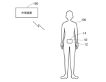
- FIG. 2 is an explanatory diagram illustrating a state in which the monitoring device shown in FIG. 1 is worn by a user.
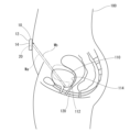
- FIG. 3 is an explanatory diagram conceptually illustrating how ultrasound is irradiated onto the bladder by the monitoring device shown in FIG.
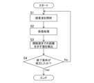
- FIG. 4 is a flowchart illustrating a flow of distance measurement control executed by the monitoring device shown in FIG.
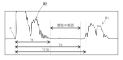
- FIG. 5 is an explanatory diagram illustrating an example of a waveform obtained by the receiving unit receiving a reflected wave.
- FIG. 6 is an explanatory diagram illustrating an example of a waveform obtained by the receiving unit receiving a reflected wave, which is different from that in FIG.
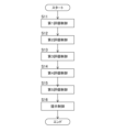
- FIG. 7 is a flowchart illustrating the flow of evaluation control performed by the condition evaluation system of the first embodiment.
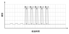
- FIG. 8 is a graph showing an example of a waveform obtained by the first evaluation control.
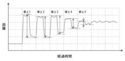
- FIG. 9 is a graph showing an example of a waveform obtained by the first evaluation control, which is different from the waveform in FIG.
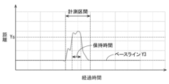
- FIG. 10 is a graph showing an example of a waveform obtained by the second evaluation control.
- FIG. 11 is a graph showing an example of a waveform obtained by the second evaluation control, which is different from the waveform in FIG.
- FIG. 12 is a graph showing an example of a waveform obtained by the second evaluation control, which is different from the waveforms in FIG. 10 and FIG. FIG.
- FIG. 13 is a graph showing an example of a waveform obtained in the third evaluation control.
- FIG. 14 is a graph showing an example of a waveform obtained by the third evaluation control, which is different from the waveform in FIG.
- FIG. 15 is a graph showing an example of a waveform obtained by the third evaluation control, which is different from the waveforms in FIG. 13 and FIG. 14 .
- FIG. 16 is a graph showing an example of a waveform obtained in the fourth evaluation control.
- FIG. 17 is a graph showing an example of a waveform obtained by the fourth evaluation control, which is different from the waveform in FIG.
- FIG. 18 is a graph showing an example of a waveform obtained in the fifth evaluation control.
- FIG. 19 is a graph showing an example of a waveform obtained by the fifth evaluation control, which is different from the waveform in FIG.
- FIG. 20 is an explanatory diagram showing an example of output in presentation control, which is an example of the image output process.
- FIG. 21 is an explanatory diagram showing an output example in presentation control, which is different from that in FIG.
- FIG. 22 is an explanatory diagram showing an example of output in the transition output process.
- FIG. 23 is an explanatory diagram showing an example of an output in the transition output process, which is different from that in FIG.
- FIG. 24 is an explanatory diagram showing an application example of the system according to the first embodiment.
- a method for assessing the condition of the pelvic floor muscles including:
- the pelvic floor muscle condition evaluation method described in [1] can present the user with quantitative evaluation results regarding the condition of the pelvic floor muscles.
- An ultrasonic transmission/reception unit having an irradiation unit that irradiates ultrasonic waves and a receiving unit that receives reflected waves of the ultrasonic waves, an irradiation step of irradiating the ultrasonic wave into the body of the user from the irradiation unit; a receiving step of receiving the reflected wave of the ultrasonic wave reflected at the bottom of the bladder of the user by the receiving unit; a measurement step of measuring the parameter by a measurement unit based on a reception result of the receiving unit;
- the method for evaluating the state of the pelvic floor muscles according to [1],
- the pelvic floor muscle condition evaluation method described in [2] irradiates ultrasound into the user's body with an irradiation unit, and can measure parameters related to the position of the bladder base based on the reception results of the reflected ultrasound. Therefore, this condition evaluation method can measure parameters related to the position of the bladder base while minimizing invasiveness, and present the user with a quantitative evaluation result regarding the state of the pelvic floor muscles.
- the pelvic floor muscle condition evaluation method described in [3] can determine a pelvic floor muscle training method based on the evaluation value calculated in the evaluation process, and therefore can determine a more appropriate training method that reflects the quantitative evaluation results regarding the state of the pelvic floor muscles. Furthermore, this condition evaluation method can present the training method thus determined to the user, and the user can adopt an appropriate training method that reflects the state of their own pelvic floor muscles for their own training.
- the determination unit has a training determination method associated with the type of the evaluation value, the training determination method determines a training method that increases the evaluation value of the corresponding type, and determines a training method with a higher intensity as the evaluation value of the corresponding type is lower,
- the pelvic floor muscle condition evaluation method described in [4] makes it easy to determine a training method that will increase the evaluation value of any type when the evaluation value is calculated. Furthermore, this condition evaluation method makes it easy to determine a training method with higher intensity the lower the evaluation value, making it easy to determine a training method that matches the degree of the quantitative index (evaluation value) of the state of the user's pelvic floor muscles.
- the parameters include a movement distance between a position of the bladder base in a relaxed state and a position of the bladder base in a contracted state when the pelvic floor muscle switches between the relaxed state and the contracted state,
- the method for evaluating the state of the pelvic floor muscles described in [5] can quantitatively evaluate the maximum extent to which the pelvic floor muscles can be moved when the user switches the pelvic floor muscles between a relaxed state and a contracted state multiple times.
- the parameters include a movement distance of the bladder bottom based on a position of the bladder bottom in a relaxed state and a contracted state of the pelvic floor muscle, and an elapsed time from when the movement distance exceeds a threshold value,
- the pelvic floor muscle condition evaluation method described in [6] can quantitatively evaluate how long a contracted state in which the movement distance exceeds a threshold can be maintained when a user switches the pelvic floor muscles between a relaxed state and a contracted state.
- the parameters include information indicative of a position of the bladder bottom when an action of switching the pelvic floor muscles between a relaxed state and a contracted state is performed for a predetermined time, A method for evaluating the state of a pelvic floor muscle as described in any one of [1] to [6], in which, in the evaluation step, when a predetermined number of the actions have been performed, it is determined for each action based on information indicating the position of the bladder base whether or not the conditions that the bladder base is maintained in a predetermined close state within a predetermined time period and that the bladder base is maintained in a predetermined distant state that is further away than the predetermined close state within a predetermined time period are satisfied, and the number of times that the conditions are satisfied is calculated as the evaluation value.
- the pelvic floor muscle condition evaluation method described in [7] can quantitatively evaluate the explosive power of a user who switches between a relaxed and contracted state of the pelvic floor muscles a specified number of times.
- the parameter includes information indicating a position of the bladder base in a relaxed state in a movement in which the pelvic floor muscle switches between a relaxed state and a contracted state,
- the method for evaluating the state of the pelvic floor muscles described in [8] can quantitatively evaluate the degree to which the user is relaxed in a relaxed state when the user switches the pelvic floor muscles between a relaxed state and a contracted state.
- the pelvic floor muscle condition evaluation method described in [9] can output an evaluation image that reflects the evaluation value, allowing the user to visually understand the condition of their own pelvic floor muscles through the evaluation image.
- the pelvic floor muscle condition evaluation method described in [10] can quantitatively show how the condition of the user's pelvic floor muscles is changing.
- the pelvic floor muscle condition evaluation method described in [11] can output a relative evaluation of the target user, which can be useful for improving the target user's condition.
- a pelvic floor muscle condition evaluation system that performs the pelvic floor muscle condition evaluation method described in [2] above, A wearable device having the ultrasonic transmission/reception unit and worn on the body of the user, the measurement unit, and an evaluation unit that performs the evaluation step,
- the measurement unit is provided in the wearable device,
- the evaluation unit is provided in at least one of the wearable device and an external device that communicates with the wearable device.
- the pelvic floor muscle condition evaluation system described in [12] can measure parameters related to the position of the bladder base by having the user wear a wearable device having an ultrasound transmitter/receiver. This allows the user to move more easily when measuring the parameters.
- First embodiment 1-1 Basic configuration of monitoring device 10, etc.
- Fig. 1 illustrates a monitoring device 10, etc. according to the first embodiment.
- the monitoring device 10 illustrated in Fig. 1 is a wearable device that is worn on the body of a user 100 as shown in Fig. 2, and monitors the inside of the body of the user 100.
- the monitoring device 10 functions as a bladder fundus monitoring apparatus that irradiates ultrasound into the body of the user 100 and monitors the movement of the bladder fundus 112 of the user 100 by ultrasound.
- the monitoring device 10 includes an ultrasonic generating element 20, a control unit 30, a transmission/reception circuit 40, a communication unit 32, and an alarm unit 34.
- the monitoring device 10 is capable of communicating with an external device 190.
- the monitoring system 1 includes the monitoring device 10 and the external device 190.
- the monitoring device 10 of the first embodiment has a housing 14, each component (ultrasonic generating element 20, control unit 30, transmission/reception circuit 40, communication unit 32, notification unit 34, etc. shown in FIG. 1) that is provided integrally with the housing 14, and an attachment unit that attaches the housing 14 to the user 100.
- Each component (ultrasonic generating element 20, control unit 30, transmission/reception circuit 40, communication unit 32, notification unit 34, etc.) is housed inside the housing 14.
- the housing 14 constitutes the wearable body 12.
- the housing 14 and each component are provided integrally with each other, but this is not limited thereto, and among the components, the control unit 30, transmission/reception circuit 40, communication unit 32, notification unit 34, etc. may be provided separately from the housing 14.
- the attachment portion is omitted.
- the attachment portion is a fastener (clip, belt, tape, etc.) that secures the housing 14 to the body of the user 100 or to something worn by the user 100 (clothing, etc.).
- the attachment portion may be configured to allow the monitoring device 10 to be attached to the user 100 in a predetermined positional state.
- the predetermined positional state is a positional state in which the ultrasound emitted from the ultrasound generating element 20 strikes the bladder bottom 112 (FIG. 3).
- the bladder bottom 112 is a portion that is configured by a predetermined site (bladder bottom position) that constitutes the inner wall of the bladder 110 inside the body of the user 100 and a group of tissues consisting of the pelvic floor muscles.
- the ultrasonic generating element 20 is an element that functions as both an ultrasonic element for transmitting waves and an ultrasonic element for receiving waves, and corresponds to an example of an ultrasonic transmitting/receiving unit.
- the ultrasonic generating element 20 corresponds to an example of an irradiating unit, and has the function of irradiating ultrasonic waves.
- the ultrasonic generating element 20 corresponds to an example of a receiving unit, and has the function of receiving reflected waves (ultrasound waves) that are returned after the ultrasonic waves irradiated by the irradiating unit are reflected by an object.
- the ultrasonic generating element 20 is composed of a piezoelectric element.
- a transmission signal (drive signal) of a predetermined resonant frequency When a transmission signal (drive signal) of a predetermined resonant frequency is applied, it emits ultrasonic waves based on the bending vibration of the transducer.
- the ultrasonic generating element 20 emits ultrasonic waves corresponding to the transmission signal in a predetermined direction.
- the ultrasonic waves emitted in a predetermined direction from the ultrasonic generating element 20 are reflected by an object present in the predetermined direction, the reflected waves generated by the reflection are received by the ultrasonic generating element 20.
- the ultrasonic generating element 20 converts the reflected waves (ultrasound waves) received by itself into electrical signals. The method of calculating distance based on the received waveform will be described later.
- the transmission/reception circuit 40 includes a signal generation circuit 42 and a reception circuit 44.
- the ultrasonic generating element 20 and the transmission/reception circuit 40 function as an ultrasonic sensor.
- the signal generating circuit 42 includes an electric circuit that drives the ultrasonic generating element 20 to generate ultrasonic waves.
- the signal generating circuit 42 includes, for example, an oscillation circuit that generates an AC signal, and an amplification circuit that amplifies the AC signal generated by the oscillation circuit and supplies the amplified signal to the ultrasonic generating element 20.
- the signal generating circuit 42 drives the ultrasonic generating element 20 in response to instructions from the control unit 30.
- the receiving circuit 44 includes, for example, an amplifier circuit, a low-pass filter circuit, and an AD conversion circuit.
- the amplifier circuit generates an amplified signal by amplifying the received signal generated by the ultrasonic generating element 20 when the ultrasonic generating element 20 receives ultrasonic waves (e.g., reflected waves).
- the low-pass filter circuit performs low-pass filtering to remove high-frequency components from the amplified signal generated by the amplifier circuit.
- the AD conversion circuit converts the signal (see Figures 5 and 6) from which the high-frequency components have been removed by the low-pass filter circuit (a signal indicating the reception result) into digital data and provides it to the control unit 30.
- the receiving circuit 44 described here is merely an example, and any configuration that can provide a signal indicating the received waveform of the receiving unit to the control unit 30 may be used.
- the receiving circuit 44 may be configured to convert the amplified signal generated by the amplifier circuit into digital data and provide it to the control unit 30.
- the control unit 30 functions as a control means for controlling the operation of the entire monitoring device 10.
- the control unit 30 is an information processing device having various information processing functions such as a calculation function, a memory function, an input/output function, and a read function.
- the control unit 30 is configured with a control device such as an MCU (Micro Controller Unit).
- the control unit 30 may also have a memory, a timer, etc.
- the communication unit 32 is a device that communicates with an external device using a publicly known wireless communication method or a wired communication method.
- the communication unit 32 can perform wireless communication with the external device 190 using a publicly known wireless communication method.
- the communication unit 32 cooperates with the control unit 30 to transmit various information to the external device 190.
- the communication unit 32 also cooperates with the control unit 30 to receive various information from the external device 190.
- the external device 190 is an information processing device such as a smartphone, a tablet terminal, or a personal computer.
- the external device 190 has a display device (such as an image display device), an audio output device (such as a speaker), a storage device, a communication device, etc.
- the external device 190 communicates with the monitoring device 10, has a function of receiving information from the monitoring device 10, and has a function of transmitting information to the monitoring device 10.
- the notification unit 34 has a display device that displays information such as numbers and symbols. Furthermore, the notification unit 34 has an audio output device such as a speaker.
- the monitoring device 10 can perform the distance measurement control shown in FIG. 4.
- a storage unit provided inside or outside the control unit 30 stores a program for executing the control of FIG. 4.
- the control unit 30 executes the program and performs the control of FIG. 4 according to the program.
- the above-mentioned "predetermined start condition" may be a predetermined operation performed on an operation unit (not shown) provided on the monitoring device 10, or may be other conditions being met (for example, the power is turned on, a predetermined reservation time arrives, etc.).
- the execution of each evaluation operation described later is also one of the "predetermined start conditions".
- the control unit 30 starts the control of FIG. 4 in response to the establishment of the above-mentioned "predetermined start condition," and first performs the process of step S1.
- the process of step S1 is a process of causing the ultrasonic generating element 20 to generate ultrasonic waves, and corresponds to an example of an irradiation process.
- the control unit 30 gives a command to the signal generating circuit 42, and causes the signal generating circuit 42 to perform the operation of driving the ultrasonic generating element 20 (the operation of generating ultrasonic waves).
- step S2 is a process of acquiring a "signal indicating the reception result of the ultrasonic generating element 20" provided by the receiving circuit 44 for a certain period of time (predetermined monitoring time) from immediately after ultrasonic waves are generated by the ultrasonic generating element 20 in the process of step S1.
- the "signal indicating the reception result of the ultrasonic generating element 20" is exemplified in Figures 5 and 6.
- the "signal indicating the reception result of the ultrasonic generating element 20" shown in Figures 5 and 6 is a signal obtained by removing high-frequency components from an amplified signal obtained by amplifying the reception signal generated by the ultrasonic generating element 20 when it receives ultrasonic waves.
- step S3 is a process of detecting the distance to the bladder bottom 112 based on the "signal indicating the reception result of the ultrasound generating element 20" obtained in the process of step S2.
- the ultrasound generating element 20 irradiation unit
- the ultrasound generating element 20 receives the reflected wave Wb (ultrasound) from the bladder bottom 112 based on the ultrasound Wa from the ultrasound generating element 20.
- the "signal indicating the reception result of the ultrasound generating element 20" includes time information indicating the distance from the ultrasound generating element 20 to the bladder bottom 112.
- the process of step S2 performed in the state shown in FIG. 3 corresponds to an example of a receiving process, and is a process in which the receiving unit receives the reflected wave of the ultrasound reflected at the bladder bottom 112 of the user 100.
- control unit 30 analyzes the "signal indicating the reception result of the ultrasound generating element 20" obtained in step S2, and detects the elapsed time from the "predetermined reference time” to the "time at which the reflected wave from the bladder base 112 is detected.”
- FIGS. 5 and 6 show the reflected waveform (waveform of the signal indicating the reception result of the ultrasound generating element 20) when ultrasound is irradiated from the ultrasound generating element 20 toward the bladder 110 with the monitoring device 10 placed on the lower abdomen of the user 100 as in FIG. 3 and positioned so that the ultrasound reaches the bladder bottom 112.
- FIG. 5 shows the reflected waveform when the user 100 is in a normal state with the pelvic floor muscles 120 relaxed (solid line state in FIG. 3).
- FIG. 6 shows the reflected waveform when the user 100 is in a state where the user 100 is exerting force as if tightening the pelvic floor muscles 120 (double-dotted chain line state in FIG. 3).
- the reflected waveform R2 on the side closer to the body surface of the user 100 is a reflected waveform from muscles, subcutaneous fat, the anterior wall of the bladder, etc.
- the reflected waveform R1 on the side farther from the body surface of the user 100 shows the bladder bottom 112 and the body tissue behind the bladder bottom 112. Because there is urine inside the bladder 110, there is almost no reflection and the amplitude indicating the reflection intensity is low.
- the rise time of the first reflected wave is set as the reference time P.
- the time (elapsed time) from the reference time P to the end time of the reflected waveform R2 is set as Tf
- the time (elapsed time) from the reference time P to the rise time of the reflected waveform R1 is set as Tb.
- the waveform in the range from the reference time P until the time Tf has elapsed until the time Tb has elapsed is set as the waveform in the range within the bladder 110.
- the peak level (amplitude level) in the “waveform in the range within the bladder 110" is set as the reference peak level.
- the peak closest to the reference time P (the peak with the earliest time) is set as the peak showing the position of the bladder bottom 112 (the bladder bottom peak).
- the time T from the reference time P to the bladder bottom peak is defined as the "value indicating the distance from the monitoring device 10 to the bladder bottom 112.”
- the time T is T1.
- the time T is Tt.
- step S3 the value (time T) indicating the distance from the monitoring device 10 to the bladder bottom 112 is detected.
- step S4 is a process for judging whether or not a predetermined end condition has been met after the start of the control of FIG. 4.
- the predetermined end condition is that a certain time has elapsed since the start of the control of FIG. 4.
- the predetermined end condition is not limited to this example, and the end condition may be, for example, that a predetermined operation has been performed after the start of the control of FIG. 4. If the control unit 30 judges in step S4 that the predetermined end condition has not been met, it returns the process to step S1, and if it judges that the predetermined end condition has been met, it ends the control of FIG. 4.
- the monitoring device 10 can obtain a waveform showing the change over time in the "value indicating the distance from the monitoring device 10 to the bladder base 112" from the satisfaction of the start condition to the satisfaction of the end condition.
- the monitoring device 10 may perform the evaluation control shown in FIG. 7.
- the evaluation control is a control in which one or more evaluation values related to the state of the pelvic floor muscles are calculated based on parameters related to the position of the bladder bottom, and the calculated evaluation values are presented to the user.
- the process of the monitoring device 10 performing the processes of steps S11 to S15 is an evaluation process in which one or more evaluation values related to the state of the pelvic floor muscles are calculated based on parameters related to the position of the bladder bottom.
- the process of the monitoring device 10 performing the process of step S16 is an evaluation value presentation process in which the evaluation value is presented to the user.
- the monitoring system 1 corresponds to an example of a pelvic floor muscle state evaluation system, and implements a pelvic floor muscle state evaluation method including such an evaluation process and an evaluation value presentation process.
- the control unit 30 corresponds to an example of an evaluation unit, and functions to perform the evaluation process.
- the control unit 30 corresponds to an example of a measurement unit, and functions to measure various parameters based on the reception results of the ultrasound generating element 20 (reception unit).
- the process in which the monitoring device 10 performs steps S11 to S15 corresponds to an example of a measurement process, which is a process in which the control unit 30 (measurement unit) measures parameters based on the reception results of the ultrasonic generating element 20 (receiving unit).
- a storage unit provided inside or outside the control unit 30 stores a program for executing the control of FIG. 7.
- the control unit 30 executes the above program and performs the control of FIG. 7 according to the above program.
- the condition for starting evaluation control may be that a specified operation has been performed on an operation unit (not shown) provided on the monitoring device 10, or that another condition has been met (for example, the power has been turned on, a predetermined reservation time has arrived, etc.).
- the control unit 30 executes the control of FIG. 7 and performs the first evaluation control in step S11.
- the first evaluation control is a control that performs the above-mentioned distance measurement control shown in FIG. 4, and then analyzes the waveform obtained by the distance measurement control to calculate an evaluation value.
- the control unit 30 first performs the above-mentioned distance measurement control and obtains waveform data that indicates the correspondence between the elapsed time since the start of the distance measurement control and the "value indicating the distance from the monitoring device 10 to the bladder bottom 112".
- This waveform data can be expressed as a value indicating the distance to the bladder bottom for each time, as shown in FIG. 8.
- the horizontal axis indicates the elapsed time
- the vertical axis indicates the value indicating the distance to the bladder bottom.
- the control unit 30 When performing distance measurement control in the first evaluation control, the control unit 30 preferably cooperates with the notification unit 34 to give the user an instruction for measuring the maximum lift.
- This instruction for measuring the maximum lift is an instruction to convey the action to be performed by the user in step S11, and is an instruction to convey the action to be performed by the user when performing distance measurement to calculate the maximum lift.
- the control unit 30 performs a first voice instruction during the period from starting distance measurement control in response to the start of the first evaluation control until the end of the distance measurement control.
- the first voice instruction is, for example, an instruction to perform repeated voice output after performing voice output instructing normal breathing.
- the voice output instructing normal breathing is, for example, a voice output by the notification unit 34 issuing a message saying "Please breathe normally".
- the repeated voice output is, for example, a voice output in which the notification unit 34 outputs a voice saying "Inhale” and then waits for a certain time (for example, 5 seconds), and the notification unit 34 outputs a voice saying "Exhale” and then waits for a certain time (for example, 5 seconds), alternately repeated a predetermined number of times (for example, 3 times).
- the control unit 30 After issuing such a first voice instruction, the control unit 30 issues a second voice instruction.
- the second voice instruction is, for example, a voice instruction to contract the pelvic floor muscles by outputting a voice of "Contract while exhaling" by the notification unit 34, and then a voice instruction to wait for a certain period of time (e.g., 5 seconds).
- the control unit 30 issues a third voice instruction after such a second voice instruction.
- the third voice instruction is, for example, a voice instruction to relax the pelvic floor muscles by outputting a voice of "Take a breath and relax" by the notification unit 34, and then a voice instruction to wait for a certain period of time (e.g., 5 seconds).
- the control unit 30 alternately repeats the second and third voice instructions a predetermined number of times (e.g., 5 times) to give the user instructions for measuring the maximum lift amount.
- a waveform such as that shown in FIG. 8 or FIG. 9 is obtained during the period when the instruction to measure the maximum lift amount is given.
- the "convex waveforms" indicated as lifts 1 to 5 are convex waveforms obtained upon each second voice instruction, and the "waveforms with reduced values” following each convex waveform are reduced waveforms obtained upon each third voice instruction.
- control unit 30 when the control unit 30 performs evaluation value calculation processing after distance measurement control, it finds the maximum value Y1 in the "convex waveform" during the period of the second voice instruction, finds the minimum value Y2 in the "waveforms with reduced values” obtained upon the third voice instruction immediately after this second voice instruction, and finds the value ⁇ Y1 of Y1-Y2, which is the difference between the maximum value Y1 and the minimum value Y2. Note that when finding the maximum value Y1 of the "convex waveform", the maximum value during the period from the start of the second voice instruction until the first predetermined time has elapsed or until the start of the next third voice instruction may be set to Y1.
- the minimum value during the period from the start of the third voice instruction until the second predetermined time has elapsed or until the start of the next second voice instruction may be set as Y2.
- the ⁇ Y1 obtained in this way is set as the lift amount in the contraction operation that caused the maximum value Y1 and the minimum value Y2 for calculating the ⁇ Y1.
- the control unit 30 obtains such a value ⁇ Y1 (lift amount) for each contraction operation (each second voice instruction), and sets the maximum value of the multiple values ⁇ Y1 (lift amount) obtained by each contraction operation (each second voice instruction) as the maximum lift amount Ym.
- the lift amount ⁇ Y1 corresponds to an example of a parameter and corresponds to an example of "the movement distance between the position of the bladder base in the relaxed state and the position of the bladder base in the contracted state in the operation in which the pelvic floor muscle switches between the relaxed state and the contracted state".
- the maximum lift amount Ym corresponds to an example of an evaluation value and corresponds to an example of "the maximum value of the multiple movement distances measured in the above operation that is determined in advance". Note that FIG. 8 shows an example in which contraction and relaxation movements are performed normally, and FIG. 9 shows an example in which relaxation is insufficient due to hypertonia.
- the maximum lift amount can be calculated as described above, but it is also possible to obtain, for example, the lift amount in each contraction movement, and the maximum and minimum values in each contraction movement. Furthermore, the control unit 30 can also calculate the average value Ya of each ⁇ Y1 (each lift amount) obtained for each contraction movement. For example, in the examples of FIG. 8 and FIG. 9, the average value of the five lift amounts ⁇ Y1 obtained in five contraction movements can be calculated as the average value Ya.
- the control unit 30 performs the first evaluation control in step S11, and then performs the second evaluation control in step S12.
- the second evaluation control is a control that performs the above-mentioned distance measurement control shown in FIG. 4, and then analyzes the waveform obtained by the distance measurement control to calculate an evaluation value.
- the control unit 30 first performs the above-mentioned distance measurement control, and obtains waveform data that indicates the correspondence between the elapsed time since the start of the distance measurement control and the "value indicating the distance from the monitoring device 10 to the bladder base 112."
- the control unit 30 When performing distance measurement control in the second evaluation control, it is desirable for the control unit 30 to cooperate with the notification unit 34 to give the user instructions for measuring the retention time.
- the instructions for measuring the retention time are instructions that convey the action that the user should take in step S12, and are instructions that convey the action that the user should take to calculate the retention time.
- the control unit 30 issues a fourth voice instruction after starting distance measurement control in conjunction with the start of the second evaluation control and before terminating the distance measurement control.
- the fourth voice instruction can be, for example, the same as the first voice instruction, and in this case, is an instruction to repeatedly output voice after outputting voice instructing normal breathing.
- the voice output instructing normal breathing is, for example, a voice output by the notification unit 34 issuing a message saying, "Please breathe normally."
- the repeated voice output is, for example, a voice output in which the notification unit 34 outputs the voice "Inhale” and then waits for a certain period of time (e.g., 5 seconds), and then outputs the voice "Exhale” and then waits for a certain period of time (e.g., 5 seconds), and this action is repeated a predetermined number of times (e.g., 3 times).
- the control unit 30 issues a fifth voice instruction.
- the fifth voice instruction is, for example, a voice instruction to contract the pelvic floor muscles by outputting the voice, "Keep breathing as is and contract your muscles," and then waits for a certain period of time Tb (for example, 10 seconds).
- Tb for example, 10 seconds
- the control unit 30 issues a sixth voice instruction.
- the sixth voice instruction is, for example, a voice instruction to relax the pelvic floor muscles by outputting the voice, "Take a breath and relax,” and then waits for a certain period of time (for example, 10 seconds).
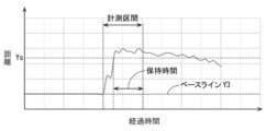
- control unit 30 gives the user an instruction to measure the above-mentioned retention time during the period in which the control unit 30 is performing distance measurement control in the second evaluation control, then during this period, waveforms such as those shown in Figures 10 to 12 are obtained.
- Figure 10 is an example of a waveform when endurance is normal
- Figure 11 is an example of a waveform when endurance is weak
- Figure 12 is an example of a waveform when there is hypertension.
- the "convex waveform” is a waveform obtained during the fifth instruction operation.
- the "waveform with a decreasing value” is a decreasing waveform obtained during the sixth voice instruction.
- the maximum value in the "waveform with a decreasing value” is set as the reference value Y3 (baseline).
- a predetermined percentage of the average value Ya calculated in the first evaluation control described above (for example, 60% of the average value Ya) is set as the threshold value Ys. After setting the premise value in this way, the control unit 30 calculates the time at which the threshold value Ys is exceeded in the "convex waveform" described above, and sets this as the retention time Te.
- each value specified in the "convex waveform" obtained in the second evaluation control corresponds to an example of a parameter, and corresponds to an example of the "distance of movement of the bladder bottom based on the position of the bladder bottom in a relaxed state in an operation in which the pelvic floor muscles switch between a relaxed state and a contracted state".
- the retention time Te corresponds to an example of a parameter, and corresponds to an example of the "time elapsed since the distance of movement of the bladder bottom exceeded the threshold value".
- the ratio (Te/Tb) of the holding time Te to the fixed time during the fifth voice instruction is calculated as the value E indicating endurance.
- the ratio (Te/Tb) may be expressed as (Te/Tb) x 100 (%).
- the value E indicating endurance corresponds to an example of an evaluation value, and corresponds to an example of a ratio of the elapsed time (holding time Te) to the specified time (fixed time Tb).
- the control unit 30 After performing the second evaluation control in step S12, the control unit 30 performs the third evaluation control in step S13.
- the third evaluation control is a control that performs the above-mentioned distance measurement control shown in FIG. 4, and then analyzes the waveform obtained by the distance measurement control to calculate an evaluation value.
- the control unit 30 first performs the above-mentioned distance measurement control, and obtains waveform data that indicates the correspondence between the elapsed time since the start of the distance measurement control and the "value indicating the distance from the monitoring device 10 to the bladder base 112."
- the instructions for measuring explosive power are instructions that convey the action that the user should take in step S13, and are instructions that convey the action that the user should take in calculating a value indicating explosive power.
- the control unit 30 issues a seventh voice instruction after starting distance measurement control in conjunction with the start of the third evaluation control and before terminating the distance measurement control.
- the seventh voice instruction can be, for example, the same as the first voice instruction, and in this case, is an instruction to output a voice instructing normal breathing, followed by repeated voice output.
- the voice output instructing normal breathing is, for example, a voice output by the notification unit 34 issuing a message saying, "Please breathe normally."
- the repeated voice output is, for example, a voice output in which the notification unit 34 outputs the voice "Inhale” and then waits for a certain period of time (e.g., 5 seconds), and then outputs the voice "Exhale” and then waits for a certain period of time (e.g., 5 seconds), and this action is repeated a predetermined number of times (e.g., 3 times).
- the eighth voice instruction is, for example, a voice instruction to contract the pelvic floor muscles by outputting the voice, "Contract without holding your breath,” and then waits for a certain period of time Tc (for example, 1 second).
- the ninth voice instruction is, for example, a voice instruction to relax the pelvic floor muscles by outputting the voice, "Relax without holding your breath,” and then waits for a certain period of time (for example, 1 second).
- the control unit 30 repeats this operation of alternating between the eighth and ninth voice instructions a predetermined number of times (for example, 10 times).
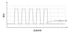
- control unit 30 gives the user instructions for measuring explosive power described above during the period in which it is performing distance measurement control in the third evaluation control, then during this period, waveforms such as those shown in Figures 13 to 15 are obtained.
- Figure 13 is an example of a waveform when explosive power is normal
- Figure 14 is an example of a waveform when explosive power is weak
- Figure 15 is an example of a waveform when explosive power is weak due to hypertension.
- the maximum value of the multiple "waveforms with reduced values" obtained during the period of the multiple ninth voice instructions is set as the reference value Y4 (baseline). Furthermore, the first predetermined percentage of the maximum lift amount Ym calculated by the first evaluation control described above (e.g., 60% of the maximum lift amount Ym) is set as the first threshold value Ys1. Furthermore, the second predetermined percentage of the maximum lift amount Ym (e.g., 10% of the maximum lift amount Ym) is set as the second threshold value Ys2.
- the control unit 30 counts the number of times Xr that the condition of "a combination in which the time during which the "convex waveform" corresponding to the eighth voice instruction is equal to or greater than the first threshold value is equal to or greater than the first time (e.g., 0.2 seconds) and the time during which the "waveform with reduced values” corresponding to the ninth voice instruction immediately after the eighth voice instruction is equal to or less than the second threshold value is equal to or greater than the second time (e.g., 0.2 seconds)" is satisfied.
- the ratio (Xr/Xa) of the number of times Xr to the total number of times Xa (e.g., 10 times) of the action of alternately performing the eighth voice instruction and the ninth voice instruction is calculated as a value indicating the instantaneous amount.
- the ratio (Xr/Xa) may be expressed as (Xr/Xa) x 100 (%).
- each value specified by the waveform obtained by the third evaluation control corresponds to an example of a parameter, and corresponds to an example of "information indicating the position of the bladder bottom when an action of switching between a relaxed state and a contracted state of the pelvic floor muscle is performed in a predetermined time".
- the control unit 30 judges for each of the above actions whether the condition "the bladder bottom is maintained in a predetermined close state within a predetermined time, and the bladder bottom is maintained in a predetermined distant state that is farther away than the predetermined close state within a predetermined time" is satisfied based on the information indicating the position of the bladder bottom.
- the number of times Xr corresponds to an example of an evaluation value, and corresponds to an example of "the number of times that the above condition is satisfied".
- the ratio (Xr/Xa) of the number of times Xr to the total number of times Xa e.g., 10 times also corresponds to an example of an evaluation value.
- the fourth evaluation control is a control that performs the above-mentioned distance measurement control shown in FIG. 4, and then analyzes the waveform obtained by the distance measurement control to calculate an evaluation value.
- the control unit 30 first performs the above-mentioned distance measurement control, and obtains waveform data that indicates the correspondence between the elapsed time since the start of the distance measurement control and the "value indicating the distance from the monitoring device 10 to the bladder base 112."
- the instructions for measuring the relaxed state are instructions that convey the action that the user should take in step S14, and are instructions that convey the action that the user should take in calculating a value indicating the relaxed state.
- the control unit 30 issues a tenth voice instruction after starting distance measurement control in conjunction with the start of the fourth evaluation control and before terminating the distance measurement control.
- the tenth voice instruction can be, for example, the same as the first voice instruction, and in this case, is an instruction to output a voice instructing normal breathing, followed by repeated voice output.
- the voice output instructing normal breathing is, for example, a voice output by the notification unit 34 issuing a message saying, "Please breathe normally."
- the repeated voice output is, for example, a voice output in which the notification unit 34 outputs the voice "Inhale” and then waits for a certain period of time (e.g., 5 seconds), and then outputs the voice "Exhale” and then waits for a certain period of time (e.g., 5 seconds), and this action is repeated a predetermined number of times (e.g., 3 times).
- the eleventh voice instruction is, for example, a voice instruction to contract the pelvic floor muscles by outputting the voice, "Breathe in and contract,” and then waits for a certain period of time Td (e.g., 5 seconds).
- the twelfth voice instruction is, for example, a voice instruction to relax the pelvic floor muscles by outputting the voice, "Breathe in and relax,” and then waits for a certain period of time (e.g., 5 seconds).
- the control unit 30 repeats this operation of alternating between the eleventh and twelfth voice instructions a predetermined number of times (e.g., 5 times).
- control unit 30 gives the user instructions for measuring the explosive power described above during the period in which the control unit 30 is performing distance measurement control in the fourth evaluation control
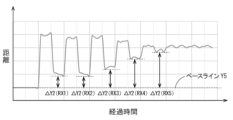
- waveforms such as those shown in Figures 16 and 17 are obtained during this period.
- Figure 16 is an example of a waveform when the state of relaxation is normal
- Figure 17 is an example of a waveform when the user is overstrained and has low endurance.
- the maximum value in the "waveform with reduced values" obtained during the period of the 10th voice instruction is set as the reference value Y5 (baseline). Then, the differences ⁇ Y2 between the maximum values Rx and the reference value Y5 in the "waveform with reduced values" during each of the periods of the 12th voice instructions are calculated. The reciprocal R of the maximum value of each difference ⁇ Y2 is set as the value indicating the relaxed state.
- each value identified in the above waveform obtained by the fourth evaluation control corresponds to an example of a parameter, and corresponds to an example of "information indicating the position of the bladder base in a relaxed state in an operation in which the pelvic floor muscles switch between a relaxed state and a contracted state.”
- the reciprocal R corresponds to an example of an evaluation value, and corresponds to an example of "information on the position where the bladder base is most contracted among the positions of the bladder base in each relaxed state in a predetermined number of the above operations (e.g., five times)."
- the control unit 30 After performing the fourth evaluation control in step S14, the control unit 30 performs the fifth evaluation control in step S15.
- the fifth evaluation control is a control that performs the above-mentioned distance measurement control shown in FIG. 4, and then analyzes the waveform obtained by the distance measurement control to calculate an evaluation value.
- the control unit 30 first performs the above-mentioned distance measurement control, and obtains waveform data that indicates the correspondence between the elapsed time since the start of the distance measurement control and the "value indicating the distance from the monitoring device 10 to the bladder base 112."
- the instructions for measuring the state of hypertension are instructions that convey the action that the user should take in step S15, and are instructions that convey the action that the user should take in calculating a value indicating the state of hypertension.
- the control unit 30 issues a thirteenth voice instruction after starting distance measurement control in conjunction with the start of the fifth evaluation control and before terminating the distance measurement control.
- the thirteenth voice instruction is, for example, an instruction to output a voice instructing normal breathing, followed by repeated voice output.
- the voice output instructing normal breathing is, for example, a voice output by the notification unit 34 issuing a message saying, "Please breathe normally."
- the repeated audio output is, for example, an audio output in which the notification unit 34 outputs the audio message "Please breathe out in a relaxed state” and then waits for a certain period of time (e.g., 5 seconds), and then outputs the audio message "Please breathe in” and then waits for a certain period of time (e.g., 5 seconds), and this action is repeated a predetermined number of times (e.g., 3 times).
- the fourteenth voice instruction is, for example, a voice instruction to push down the pelvic floor muscles by outputting the voice "Please push down", followed by a voice instruction to wait for a certain period of time Tf (e.g., five seconds).
- the fifteenth voice instruction is, for example, a voice instruction to relax the pelvic floor muscles by outputting the voice "Please release tension and relax", followed by a voice instruction to wait for a certain period of time (e.g., five seconds).
- the control unit 30 repeats this operation of alternating between the fourteenth and fifteenth voice instructions a predetermined number of times (e.g., three times).
- control unit 30 gives the user instructions for measuring the explosive power described above during the period in which the control unit 30 is performing distance measurement control in the fifth evaluation control
- waveforms such as those shown in Figures 18 and 19 are obtained during this period.
- Figure 18 is an example of a waveform when the degree of hypertension is low and normal
- Figure 19 is an example of a waveform when the degree of hypertension is high.
- the maximum value in the waveform obtained during the period of the 13th voice instruction is set as the reference value Y6 (baseline). Then, the maximum value in each "waveform with an increased value” during each period of the 15th voice instruction is set as the reference, and the difference ⁇ Y2 between this maximum value and each minimum value in each "waveform with a decreased value" during each period of the 14th voice instruction is calculated. Then, if the maximum of these differences is equal to or greater than a predetermined threshold, it is determined that the subject is "not in a state of tension,” and if the maximum of these differences is less than the predetermined threshold, it is determined that the subject is "in a state of tension.”
- step S16 the control unit 30 performs presentation control so that the evaluation results obtained in the evaluation control of steps S11 to S15 are displayed on the display device included in the notification unit 34.
- the presentation control performed in step S16 corresponds to an example of an image output process, and is a process of outputting an evaluation image reflecting the evaluation value calculated in the evaluation process.
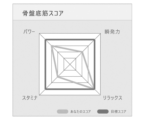
- the control unit 30 When the control unit 30 performs presentation control in step S16, the control unit 30 displays the maximum lift amount Ym as it is or after conversion as a value indicating power, displays the value E indicating endurance as it is or after conversion as a value indicating stamina, displays the ratio (Xr/Xa) of the number of repetitions Xr as it is or after conversion as a value indicating explosive power, and displays the reciprocal R as it is or after conversion as a value indicating relaxation. "Displaying as it is” means that the value itself is displayed as a numerical value, and "displaying after conversion” means that the value is displayed as a level or as a graph. Examples of display include a display method as shown in FIG. 20 and a display method as shown in FIG. 21.
- FIG. 20 and FIG. 21 figures that can identify the values or levels of the values of each evaluation item measured in the evaluation control of steps S11 to S15 are shown in comparison with the target values of each evaluation item.
- the images exemplified in FIG. 20 and FIG. 21 correspond to examples of evaluation images that reflect the evaluation values calculated in the evaluation process.
- the control unit 30 may present a training method in step S16.
- the control unit 30, which functions as a determination unit has a training determination method associated with the type of evaluation value, and this training determination method determines a training method that increases the evaluation value of the corresponding type, and determines a training method with a higher intensity as the evaluation value of the corresponding type is lower.
- the training determination method associated with the maximum lift determines a training method that increases the evaluation value of the corresponding type (maximum lift), and determines a training method with a higher intensity as the evaluation value of the corresponding type (maximum lift) is lower.
- the training determination method associated with a value indicating endurance determines a training method that increases the evaluation value of the corresponding type (value indicating endurance), and determines a training method with a higher intensity as the evaluation value of the corresponding type (value indicating endurance) is lower.
- the control unit 30 performs a determination process to determine a training method according to the training determination method associated with the type of the evaluation value based on the evaluation value calculated in the evaluation process, and performs a training presentation process to present the pelvic floor muscle training method determined in this determination process to the user.
- "training time” is used as an index showing the intensity of a training method. Therefore, a training method with a longer training time is a training method with a higher intensity.
- the maximum lift amount Ym obtained in the evaluation process is less than the threshold value Yth
- two sets of exercise program A for increasing the maximum lift amount Ym may be presented to be added to the exercise menu
- the maximum lift amount Ym obtained in the evaluation process is equal to or greater than the threshold value Yth
- one set of exercise program A for increasing the maximum lift amount Ym may be presented to be added to the exercise menu.
- a training method with a longer training time for exercise program A is determined compared to when the maximum lift amount Ym is equal to or greater than the threshold value Yth, and if the maximum lift amount Ym is equal to or greater than the threshold value Yth, a training method with a relatively shorter training time for exercise program A is determined, and the content of the training method thus determined can be notified to the user by text information, messages, etc. via the display device or audio output unit included in the notification unit 34.
- two sets of the exercise program B for improving endurance may be presented to be added to the exercise menu, and when the value E obtained in the evaluation process is equal to or greater than the threshold value Eth, one set of the exercise program B for improving endurance may be presented to be added to the exercise menu.
- a training method in which the training time of the exercise program B is longer than when the value E is equal to or greater than the threshold value Eth is determined, and when the value E is equal to or greater than the threshold value Eth, a training method in which the training time of the exercise program B is relatively shorter is determined, and the training method thus determined can be notified to the user by the display device or audio output unit included in the notification unit 34.
- the value indicating the explosive power obtained in the evaluation process (the ratio (Xr/Xa) of the number of times Xr) is less than the threshold value Zth
- two sets of the exercise program C for improving explosive power may be presented to be added to the exercise menu
- the value indicating the explosive power obtained in the evaluation process is equal to or greater than the threshold value Zth
- one set of the exercise program C for improving explosive power may be presented to be added to the exercise menu.
- a training method in which the training time of the exercise program C is longer than when the value indicating the explosive power is equal to or greater than the threshold value Zth is determined, and when the value indicating the explosive power is equal to or greater than the threshold value Zth, a training method in which the training time of the exercise program C is relatively shorter is determined, and the training method thus determined can be notified to the user by the display device or audio output unit included in the notification unit 34.
- two sets of the exercise program D for enhancing the relaxed state may be presented to be added to the exercise menu, and when the value R obtained in the evaluation process is equal to or greater than the threshold value Rth, one set of the exercise program D for enhancing the relaxed state may be presented to be added to the exercise menu.
- the control unit 30 may perform presentation control so that the specific contents of the exercise programs A, B, C, and D thus determined are displayed simultaneously or sequentially on the display device included in the notification unit 34.
- "training time” is exemplified as an index indicating the intensity of the training method, but this is not limited to this example, and the index indicating the intensity of the training method may be the number of training sessions or other indexes.
- the control unit 30 may perform a transition output process to output the transition of the evaluation value calculated in the evaluation process for that user.
- the timing to start the transition output process may be the timing of the arrival of a predetermined time (scheduled time, etc.), the timing of a predetermined operation being performed on the monitoring device 10, or other timing. For example, when the evaluation control as shown in FIG.
- the transition of the evaluation value may be displayed by the display device included in the notification unit 34 so that the values of a specific evaluation value (e.g., maximum lift amount Ym, value E indicating endurance, etc.) at each time point are shown by graphs as shown in FIG. 22 and FIG. 23.
- FIG. 22 shows the transition of one index (e.g., maximum lift amount Ym) by a graph
- FIG. 23 shows the transition of two indexes (e.g., maximum lift amount Ym and value E indicating endurance) by a graph.
- Figures 22 and 23 are just one example of a method for displaying the transition, and other methods (e.g., other types of graph formats or table formats different from Figures 22 and 23) may be used as long as they are capable of displaying the transition.
- the monitoring system 1 which corresponds to an example of a condition evaluation system, may be configured with a single wearable device (monitoring device 10), or may be configured as a system with multiple monitoring devices 10 and an external device 190 as shown in FIG. 24.
- the external device 190 may be configured as, for example, a cloud server.
- the external device 190 functions as a recording unit and can record data on the evaluation values of each of the multiple users.
- the monitoring system 1 can also perform a relative evaluation output process that outputs a relative evaluation of a target user among the multiple users based on the data accumulated in the external device 190 (recording unit).
- the timing at which the monitoring system 1 starts the relative evaluation output process may be the timing at which a predetermined time (such as a scheduled time) arrives, the timing at which a predetermined operation is performed on the monitoring device 10 or the external device 190, or other timing.
- the external device 190 can continuously acquire data (e.g., measurement waveforms, data on evaluation items, answers to questions about the user's status, etc.) from multiple monitoring devices 10 that can communicate with the external device 190, and perform statistical processing on the data obtained from each monitoring device 10. For example, the average value of each evaluation item in all monitoring devices 10 during a specified period may be calculated, or the best score or distribution of each evaluation item may be calculated. Alternatively, processing such as stratification for each user group may be performed.
- the external device 190 can transmit information indicating the results of such statistical processing to each monitoring device 10, and each monitoring device 10 may display the results of the statistical processing on a display device included in the notification unit 34 based on the information provided by the external device 190.
- the classification method is not particularly limited, and various methods of stratification are possible based on the contents of the user's medical interview, attributes, the values of the measurement results, etc.
- statistical data such as the average value, best score, and distribution of each evaluation item for all monitoring devices 10 included in the monitoring system 1 as shown in FIG. 24 may be displayed in the notification unit 34 of the monitoring device 10 that performs the display.
- the monitoring device 10 that performs the display can output information indicating the relative evaluation of the user by displaying the evaluation value of each evaluation item for the user who possesses the monitoring device 10 (target user) using text information, graphics, etc., together with the average value and the statistical data, or separately from the average value and the statistical data.
- the pelvic floor muscle condition evaluation method is capable of calculating one or more evaluation values relating to the condition of the pelvic floor muscles based on parameters relating to the position of the bladder base and presenting these evaluation values to the user, making it possible to present to the user a quantitative evaluation result regarding the condition of the pelvic floor muscles.
- the condition assessment method irradiates ultrasound into the user's body using an ultrasound generating element 20, which corresponds to an irradiation unit, and can measure parameters related to the position of the bladder bottom based on the reception results of the reflected waves of the ultrasound. Therefore, this condition assessment method can measure parameters related to the position of the bladder bottom while minimizing invasiveness, and present the user with a quantitative assessment result regarding the state of the pelvic floor muscles.
- the condition assessment method can determine the training method for the pelvic floor muscles based on the evaluation value calculated in the assessment process, and therefore can determine a more appropriate training method that reflects the quantitative assessment results regarding the state of the pelvic floor muscles. Furthermore, this condition assessment method can present the training method thus determined to the user, and the user can adopt an appropriate training method that reflects the state of their own pelvic floor muscles for their own training.
- condition assessment method calculates any type of assessment value, it is easy to determine a training method that will increase that type of assessment value. Furthermore, this condition assessment method is more likely to determine a training method with higher intensity the lower the assessment value, so it is easy to determine a training method that matches the degree of the quantitative index (assessment value) regarding the condition of the user's pelvic floor muscles.
- the state evaluation method performs the first evaluation control, making it possible to quantitatively evaluate the maximum extent to which the pelvic floor muscles can be moved when the user switches the pelvic floor muscles between a relaxed state and a contracted state multiple times.
- the state evaluation method performs the second evaluation control, making it possible to quantitatively evaluate how long a contracted state in which the travel distance exceeds a threshold can be maintained when the user switches the pelvic floor muscles between a relaxed state and a contracted state.
- the state evaluation method performs the third evaluation control, making it possible to quantitatively evaluate the explosive power of a user who switches the pelvic floor muscles between a relaxed state and a contracted state a predetermined number of times.
- the state evaluation method performs the fourth evaluation control, making it possible to quantitatively evaluate the degree to which the user is relaxed in a relaxed state when the user performs an action that switches the pelvic floor muscles between a relaxed state and a contracted state.
- the condition evaluation method can output an evaluation image that reflects the evaluation value, allowing the user to visually understand the condition of their own pelvic floor muscles through the evaluation image.
- the condition assessment method according to this embodiment can quantitatively show how the condition of the user's pelvic floor muscles is changing.
- the condition evaluation method can output a relative evaluation of the target user, which can be useful for improving the target user's condition.
- the monitoring system 1 can measure parameters related to the position of the bladder base by having the user wear a wearable device having an ultrasonic transmitter/receiver. This allows the user to move more easily when measuring the parameters.
- both the irradiation unit and the receiving unit are configured with a common ultrasonic generating element, but this is not limited to this example.
- the piezoelectric element that configures the irradiation unit and the piezoelectric element that configures the receiving unit may be different.
- the first to fifth evaluation controls are performed in the order shown in FIG. 7, but the order in which the first to fifth evaluation controls are performed may be changed from that shown in FIG. 7. Also, any of the first to fifth evaluation controls may be omitted.
- the training determination method used in the condition evaluation method according to the embodiment described above is a method of "determining a training method with a higher intensity as the evaluation value of the corresponding type is lower," but is not limited to this example. For example, when evaluation values of a first type (e.g., maximum lift) and a second type (e.g., a value indicating endurance) are obtained, even if the evaluation value of the first type is low, the evaluation value of the second type may be prioritized and a training method suitable for the evaluation value of the second type may be determined.
- a first type e.g., maximum lift
- a second type e.g., a value indicating endurance
- This determination method does not necessarily have to use the determination method of "determining a training method such that the intensity of the 'training method that increases the evaluation value of the first type' increases as the evaluation value of the first type is lower," or a training method that increases the evaluation value of the first type may not be adopted.
- the example described here is merely an example, and various determination methods may be adopted.
- the pelvic floor muscle condition evaluation system (monitoring system 1) is configured to include the external device 190, but the pelvic floor muscle condition evaluation system may be configured to not include the external device 190.
- the pelvic floor muscle condition evaluation system may be configured by only the monitoring device 10.
- the evaluation unit is provided in the monitoring device 10 (wearable device), but the evaluation unit may also be provided in an external device 190 that communicates with the wearable device.
- the notification unit 34 includes a display device and an audio output unit, but the notification unit 34 may include a lamp, a vibration device, etc. If the notification unit 34 includes a lamp, it can transmit instructions or information to the outside by a blinking state, a blinking speed, a lighting color, etc., and if it is a vibration device, it can transmit instructions or information to the outside by a vibration pattern, a vibration strength, etc.
- Monitoring system (pelvic floor muscle condition evaluation system) 10...Monitoring devices (wearable devices) 12: Wearing body 20: Ultrasonic generating element (irradiation unit, receiving unit, ultrasonic transmission/reception unit) 30...Control unit (measurement unit, determination unit) 100: User 110: Bladder 112: Bladder base 114: Bladder side wall 190: External device
Landscapes
- Health & Medical Sciences (AREA)
- Life Sciences & Earth Sciences (AREA)
- General Health & Medical Sciences (AREA)
- Medical Informatics (AREA)
- Surgery (AREA)
- Biophysics (AREA)
- Pathology (AREA)
- Engineering & Computer Science (AREA)
- Biomedical Technology (AREA)
- Heart & Thoracic Surgery (AREA)
- Orthopedic Medicine & Surgery (AREA)
- Molecular Biology (AREA)
- Physics & Mathematics (AREA)
- Animal Behavior & Ethology (AREA)
- Veterinary Medicine (AREA)
- Public Health (AREA)
- Dentistry (AREA)
- Oral & Maxillofacial Surgery (AREA)
- Physical Education & Sports Medicine (AREA)
- Nuclear Medicine, Radiotherapy & Molecular Imaging (AREA)
- Radiology & Medical Imaging (AREA)
- Measurement Of The Respiration, Hearing Ability, Form, And Blood Characteristics Of Living Organisms (AREA)
- Ultra Sonic Daignosis Equipment (AREA)
Abstract
Description
膀胱底の位置に関するパラメータに基づいて骨盤底筋の状態に関する1項目以上の評価値を算出する評価工程と、
前記評価値をユーザに提示する評価値提示工程と、
を含む。
前記評価値をユーザに提示する評価値提示工程と、
を含む骨盤底筋の状態評価方法。
前記照射部から前記ユーザの体内に前記超音波を照射する照射工程と、
前記超音波が前記ユーザの膀胱底において反射された前記反射波を前記受信部で受信する受信工程と、
前記受信部の受信結果に基づいて測定部で前記パラメータを測定する測定工程と、
を行う[1]に記載の骨盤底筋の状態評価方法 。
前記決定工程で決定された前記骨盤底筋のトレーニング方法を前記ユーザに提示するトレーニング提示工程と、
を含む[1]又は[2]に記載の骨盤底筋の状態評価方法。
前記トレーニング決定方法は、対応する種類の前記評価値を高めるトレーニング方法を定め、対応する種類の前記評価値が低いほど強度が大きいトレーニング方法を決定するように定めており、
前記決定工程では、前記評価工程で算出した前記評価値に基づき、当該評価値の種類に対応付けられた前記トレーニング決定方法に従ってトレーニング方法を決定する
[3]に記載の骨盤底筋の状態評価方法。
前記評価工程では、予め定められた複数回の前記動作で測定される複数の前記移動距離のうちの最大値を前記評価値として算出する
[1]から[4]のいずれか一つに記載の骨盤底筋の状態評価方法。
前記評価工程では、所定時間に占める前記経過時間の割合を前記評価値として算出する
[1]から[5]のいずれか一つに記載の骨盤底筋の状態評価方法。
前記評価工程では、所定数の前記動作がなされた場合に、前記膀胱底の位置を示す情報に基づき、定められた時間内に前記膀胱底が所定の接近状態で維持され、且つ、定められた時間内に前記膀胱底が前記所定の接近状態よりも離れた所定の離間状態で維持されるという条件を満たしたかどうか前記動作毎に判定し、前記条件を満たした回数を前記評価値として算出する
[1]から[6]のいずれか一つに記載の骨盤底筋の状態評価方法。
前記評価工程では、所定数の前記動作における各々の前記リラックス状態での前記膀胱底の位置のうち、前記膀胱底が最も収縮した位置の情報を評価値として算出する
[1]から[7]のいずれか一つに記載の骨盤底筋の状態評価方法。
[1]から[8]のいずれか一つに記載の骨盤底筋の状態評価方法。
[1]から[9]のいずれか一つに記載の骨盤底筋の状態評価方法。
前記記録部に蓄積されたデータに基づいて、前記複数のユーザの中での対象のユーザの相対評価を出力する相対評価出力工程を行う
[1]から[10]のいずれか一つに記載の骨盤底筋の状態評価方法。
前記超音波送受信部を有するとともに前記ユーザの体に装着されるウェアラブルデバイスと、前記測定部と、前記評価工程を行う評価部と、を含み、
前記測定部は、前記ウェアラブルデバイスに設けられ、
前記評価部は、前記ウェアラブルデバイス及び前記ウェアラブルデバイスと通信を行う外部装置の少なくともいずれかに設けられる
骨盤底筋の状態評価システム。
1-1.モニタリングデバイス10等の基本構成
図1には、第1実施形態に係るモニタリングデバイス10等が例示される。図1に例示されるモニタリングデバイス10は、図2のようにユーザ100の人体に装着されるウェアラブルデバイスであり、ユーザ100の体の内部を監視する。具体的には、図3のように、モニタリングデバイス10は、ユーザ100の体内に超音波を照射し、ユーザ100の膀胱底112の動きを超音波によって監視する膀胱底監視装置として機能する。
モニタリングデバイス10は、図4に示される距離計測制御を行い得る。モニタリングデバイス10において、制御部30の内部又は外部に設けられた記憶部には、図4の制御を実行するためのプログラムが記憶されている。制御部30は、所定の開始条件が成立した場合、上記プログラムを実行し、上記プログラムに従って図4の制御を行う。上記の「所定の開始条件」は、モニタリングデバイス10に設けられた図示されていない操作部に対して所定操作が行われたことであってもよく、その他の条件が成立したこと(例えば、電源が投入されたこと、予め定められた予約時間が到来したこと等)であってもよい。本実施形態では、後述される各評価動作が実行されることも、「所定の開始条件」の一つである。
モニタリングデバイス10は、図7に示される評価制御を行い得る。評価制御は、膀胱底の位置に関するパラメータに基づいて骨盤底筋の状態に関する1項目以上の評価値を算出し、算出した評価値をユーザに提示する制御である。具体的には、モニタリングデバイス10がステップS11~S15の処理を行う工程が、膀胱底の位置に関するパラメータに基づいて骨盤底筋の状態に関する1項目以上の評価値を算出する評価工程である。そして、モニタリングデバイス10がステップS16の処理を行う工程が、評価値をユーザに提示する評価値提示工程である。モニタリングシステム1は、骨盤底筋の状態評価システムの一例に相当し、このような評価工程及び評価値提示工程を含む骨盤底筋の状態評価方法を実施する。制御部30は、評価部の一例に相当し、評価工程を行うよう機能する。また、制御部30は、測定部の一例に相当し、超音波発生素子20(受信部)の受信結果に基づいて様々なパラメータを測定するように機能する。モニタリングデバイス10がステップS11~S15の処理を行う工程は、測定工程の一例に相当し、超音波発生素子20(受信部)の受信結果に基づいて制御部30(測定部)でパラメータを測定する工程である。
図20、図21で例示される画像は、評価工程で算出した評価値を反映した評価画像の一例に相当する。
本実施形態に係る骨盤底筋の状態評価方法は、膀胱底の位置に関するパラメータに基づいて骨盤底筋の状態に関する1項目以上の評価値を算出し、その評価値をユーザに提示することができるため、骨盤底筋の状態に関する定量的な評価結果をユーザに提示することができる。
本開示は、上記記述及び図面によって説明した実施形態に限定されるものではない。例えば、上述又は後述の実施形態の特徴は、矛盾しない範囲であらゆる組み合わせが可能である。また、上述又は後述の実施形態のいずれの特徴も、必須のものとして明示されていなければ省略することもできる。更に、上述した実施形態は、次のように変更されてもよい。
上述された実施形態では、報知部34が表示装置や音声出力部を含む構成であったが、報知部34は、ランプや振動装置などを含んでいてもよい。報知部34がランプを含む場合、点滅状態、点滅速度、点灯の色などによって指示や情報を外部に伝えることができ、振動装置であれば、振動パターンや振動の強さなどによって指示や情報を外部に伝えることができる。
10…モニタリングデバイス(ウェアラブルデバイス)
12…装着体
20…超音波発生素子(照射部、受信部、超音波送受信部)
30…制御部(測定部、決定部)
100…ユーザ
110…膀胱
112…膀胱底
114…膀胱側壁
190…外部装置
Claims (12)
- 膀胱底の位置に関するパラメータに基づいて骨盤底筋の状態に関する1項目以上の評価値を算出する評価工程と、
前記評価値をユーザに提示する評価値提示工程と、
を含む骨盤底筋の状態評価方法。 - 超音波を照射する照射部と、前記超音波の反射波を受信する受信部と、を有する超音波送受信部を用い、
前記照射部から前記超音波を照射する照射工程と、
前記超音波が前記ユーザの膀胱底において反射された前記反射波を前記受信部で受信する受信工程と、
前記受信部の受信結果に基づいて測定部で前記パラメータを測定する測定工程と、
を行う
請求項1に記載の骨盤底筋の状態評価方法。 - 前記評価工程で算出した前記評価値に基づいて前記骨盤底筋のトレーニング方法を決定部で決定する決定工程と、
前記決定工程で決定された前記骨盤底筋のトレーニング方法を前記ユーザに提示するトレーニング提示工程と、
を含む請求項1又は請求項2に記載の骨盤底筋の状態評価方法。 - 前記決定部は、前記評価値の種類に対応付けられたトレーニング決定方法を有し、
前記トレーニング決定方法は、対応する種類の前記評価値を高めるトレーニング方法を定め、対応する種類の前記評価値が低いほど強度が大きいトレーニング方法を決定するように定めており、
前記決定工程では、前記評価工程で算出した前記評価値に基づき、当該評価値の種類に対応付けられた前記トレーニング決定方法に従ってトレーニング方法を決定する
請求項3に記載の骨盤底筋の状態評価方法。 - 前記パラメータは、前記骨盤底筋がリラックス状態と収縮状態とに切り替わる動作における、前記リラックス状態での前記膀胱底の位置と前記収縮状態での前記膀胱底の位置との間の移動距離を含み、
前記評価工程では、予め定められた複数回の前記動作で測定される複数の前記移動距離のうちの最大値を前記評価値として算出する
請求項1又は請求項2に記載の骨盤底筋の状態評価方法。 - 前記パラメータは、前記骨盤底筋がリラックス状態と収縮状態とに切り替わる動作における、前記リラックス状態での前記膀胱底の位置を基準とする前記膀胱底の移動距離と、前記移動距離が閾値を超えてからの経過時間と、を含み、
前記評価工程では、所定時間に占める前記経過時間の割合を前記評価値として算出する
請求項1又は請求項2に記載の骨盤底筋の状態評価方法。 - 前記パラメータは、所定の時間で前記骨盤底筋のリラックス状態と収縮状態とを切り替える動作がなされた場合の前記膀胱底の位置を示す情報を含み、
前記評価工程では、所定数の前記動作がなされた場合に、前記膀胱底の位置を示す情報に基づき、定められた時間内に前記膀胱底が所定の接近状態で維持され、且つ、定められた時間内に前記膀胱底が前記所定の接近状態よりも離れた所定の離間状態で維持されるという条件を満たしたかどうか前記動作毎に判定し、前記条件を満たした回数を前記評価値として算出する
請求項1又は請求項2に記載の骨盤底筋の状態評価方法。 - 前記パラメータは、前記骨盤底筋がリラックス状態と収縮状態とに切り替わる動作における、前記リラックス状態での前記膀胱底の位置を示す情報を含み、
前記評価工程では、所定数の前記動作における各々の前記リラックス状態での前記膀胱底の位置のうち、前記膀胱底が最も収縮した位置の情報を評価値として算出する
請求項1又は請求項2に記載の骨盤底筋の状態評価方法。 - 前記評価工程で算出した前記評価値を反映した評価画像を出力する画像出力工程を含む
請求項1又は請求項2に記載の骨盤底筋の状態評価方法。 - 前記評価工程によって前記ユーザの前記評価値を複数回測定した場合に、前記評価工程で算出した前記評価値の推移を出力する推移出力工程を含む
請求項1又は請求項2に記載の骨盤底筋の状態評価方法。 - 複数のユーザの各々の前記評価値のデータを記録する記録部を用い、
前記記録部に蓄積されたデータに基づいて、前記複数のユーザの中での対象のユーザの相対評価を出力する相対評価出力工程を行う
請求項1又は請求項2に記載の骨盤底筋の状態評価方法。 - 請求項2に記載の骨盤底筋の状態評価方法を行う骨盤底筋の状態評価システムであり、
前記超音波送受信部を有するとともに前記ユーザの体に装着されるウェアラブルデバイスと、前記測定部と、前記評価工程を行う評価部と、を含み、
前記測定部は、前記ウェアラブルデバイスに設けられ、
前記評価部は、前記ウェアラブルデバイス及び前記ウェアラブルデバイスと通信を行う外部装置の少なくともいずれかに設けられる
骨盤底筋の状態評価システム。
Priority Applications (1)
| Application Number | Priority Date | Filing Date | Title |
|---|---|---|---|
| CN202380042521.0A CN119255756A (zh) | 2022-11-09 | 2023-09-26 | 盆底肌的状态评价方法和盆底肌的状态评价系统 |
Applications Claiming Priority (2)
| Application Number | Priority Date | Filing Date | Title |
|---|---|---|---|
| JP2022-179537 | 2022-11-09 | ||
| JP2022179537A JP2024068888A (ja) | 2022-11-09 | 2022-11-09 | 骨盤底筋の状態評価方法及び骨盤底筋の状態評価システム |
Publications (1)
| Publication Number | Publication Date |
|---|---|
| WO2024101017A1 true WO2024101017A1 (ja) | 2024-05-16 |
Family
ID=91032257
Family Applications (1)
| Application Number | Title | Priority Date | Filing Date |
|---|---|---|---|
| PCT/JP2023/034897 Ceased WO2024101017A1 (ja) | 2022-11-09 | 2023-09-26 | 骨盤底筋の状態評価方法及び骨盤底筋の状態評価システム |
Country Status (3)
| Country | Link |
|---|---|
| JP (1) | JP2024068888A (ja) |
| CN (1) | CN119255756A (ja) |
| WO (1) | WO2024101017A1 (ja) |
Citations (6)
| Publication number | Priority date | Publication date | Assignee | Title |
|---|---|---|---|---|
| JP2008206597A (ja) * | 2007-02-23 | 2008-09-11 | Isuzu Motors Ltd | 運転適性診断装置、運転適性診断プログラム及び運転適性診断プログラムが記憶された記憶媒体 |
| WO2015098977A1 (ja) * | 2013-12-25 | 2015-07-02 | 旭化成株式会社 | 脈波測定装置、携帯機器、医療機器システム、及び生体情報コミュニケーションシステム |
| WO2016199182A1 (ja) * | 2015-06-12 | 2016-12-15 | トリプル・ダブリュー・ジャパン株式会社 | 尿量推定装置及び尿量推定方法 |
| JP2022120842A (ja) * | 2021-02-05 | 2022-08-18 | Stork Visit株式会社 | エコー画像観察記録プログラム、エコー画像観察記録装置、及びエコー画像観察記録ネットワークシステム |
| CN115212529A (zh) * | 2022-07-27 | 2022-10-21 | 凉山彝族自治州第一人民医院(凉山州传染病医院) | 一种盆底肌群训练监控和评估方法及系统 |
| WO2022239404A1 (ja) * | 2021-05-11 | 2022-11-17 | 日本特殊陶業株式会社 | モニタリングデバイス |
-
2022
- 2022-11-09 JP JP2022179537A patent/JP2024068888A/ja active Pending
-
2023
- 2023-09-26 WO PCT/JP2023/034897 patent/WO2024101017A1/ja not_active Ceased
- 2023-09-26 CN CN202380042521.0A patent/CN119255756A/zh not_active Withdrawn
Patent Citations (6)
| Publication number | Priority date | Publication date | Assignee | Title |
|---|---|---|---|---|
| JP2008206597A (ja) * | 2007-02-23 | 2008-09-11 | Isuzu Motors Ltd | 運転適性診断装置、運転適性診断プログラム及び運転適性診断プログラムが記憶された記憶媒体 |
| WO2015098977A1 (ja) * | 2013-12-25 | 2015-07-02 | 旭化成株式会社 | 脈波測定装置、携帯機器、医療機器システム、及び生体情報コミュニケーションシステム |
| WO2016199182A1 (ja) * | 2015-06-12 | 2016-12-15 | トリプル・ダブリュー・ジャパン株式会社 | 尿量推定装置及び尿量推定方法 |
| JP2022120842A (ja) * | 2021-02-05 | 2022-08-18 | Stork Visit株式会社 | エコー画像観察記録プログラム、エコー画像観察記録装置、及びエコー画像観察記録ネットワークシステム |
| WO2022239404A1 (ja) * | 2021-05-11 | 2022-11-17 | 日本特殊陶業株式会社 | モニタリングデバイス |
| CN115212529A (zh) * | 2022-07-27 | 2022-10-21 | 凉山彝族自治州第一人民医院(凉山州传染病医院) | 一种盆底肌群训练监控和评估方法及系统 |
Non-Patent Citations (4)
| Title |
|---|
| ANONYMOUS: "Health Management for Female Athletes Special Version: Conditioning for Pregnant, Post-Partum, Menopausal, and Elderly Women, First Edition", THE UNIVERSITY OF TOKYO, FACULTY OF MEDICINE, OBSTETRICS AND GYNECOLOGY DEPARTMENT, 31 March 2019 (2019-03-31), XP093172126, Retrieved from the Internet <URL:https://w-health.jp/femaleathletes/document/pdf/190308_HMFASpecialVer.pdf> * |
| KAMIO HIROYO, MARUYAMA HITOSHI: "Voluntary Contraction Ability of Pelvic Floor Muscles of Young Females Measured by an Ultrasound Imaging Device", JOURNAL OF PHYSICAL THERAPY SCIENCE, vol. 34, no. 1, 26 February 2019 (2019-02-26), pages 115 - 118, XP093172123, DOI: 10.1589/rika.34.115 * |
| TAYANAKA MAYUMI, AOKI YOSHITAKA: "Fundamentals and practices for pelvic floor muscle training", TAIRYOKU KAGAKU, NIHON TAIRYOKU IGAKKAI, TOKYO, JP, vol. 71, no. 3, 1 June 2022 (2022-06-01), JP , pages 255 - 261, XP093172138, ISSN: 0039-906X, DOI: 10.7600/jspfsm.71.255 * |
| UBUKATA, HITOMI ET AL.: "Reliability of measuring pelvic floor elevation with a diagnostic ultrasonic imaging device", JOURNAL OF PHYSICAL THERAPY SCIENCE, THE SOCIETY OF PHYSICAL THERAPY SCIENCE, JP, vol. 29, no. 2, 22 March 2014 (2014-03-22) - 23 March 2014 (2014-03-23), JP, pages 31 - 32, XP009554726, DOI: 10.1589/rika.29.S2_1 * |
Also Published As
| Publication number | Publication date |
|---|---|
| JP2024068888A (ja) | 2024-05-21 |
| CN119255756A (zh) | 2025-01-03 |
Similar Documents
| Publication | Publication Date | Title |
|---|---|---|
| CN103079463B (zh) | 手臂部安装式血压计 | |
| EP3769671A1 (en) | Apparatus and method for estimating bio-information | |
| CN103815888B (zh) | 生物信号测量装置以及生物信号测量方法 | |
| CN113425269B (zh) | 生物特征信息的测量方法、装置和电子设备 | |
| EP3636146B1 (en) | Apparatus and method for estimating blood pressure | |
| KR102025571B1 (ko) | 호흡 조절에 의한 혈압 변화를 측정하기 위한 장치 및 방법 | |
| JP2006296940A (ja) | 生体センサ、脈波センサ、睡眠情報処理方法、睡眠情報処理装置、プログラム、及び記録媒体 | |
| JP2007007075A (ja) | 血圧測定装置 | |
| US11903685B2 (en) | Apparatus and method for estimating bio-information | |
| JP2007312921A (ja) | 生体情報測定装置及び生体情報測定システム | |
| JP2011103914A (ja) | 筋緊張計測装置、筋緊張計測方法および筋緊張計測プログラム | |
| JP6521420B1 (ja) | 筋電信号が由来する動作を認識するためのシステム、方法、およびプログラム | |
| JP2013123493A (ja) | 情報処理装置、聴診器、情報処理装置の制御方法、制御プログラムおよび記録媒体 | |
| JP2014076272A (ja) | 脈拍データ検出装置、脈拍データ検出方法、および脈拍データ検出プログラム | |
| CN114521915A (zh) | 瞬时弹性测量方法和超声成像系统 | |
| CN102949186B (zh) | 电子血压计 | |
| WO2019124025A1 (ja) | 測定装置およびプログラム | |
| JP2017164537A (ja) | 生体情報検出装置 | |
| CN115517640A (zh) | 用于估计生物信息的设备和方法 | |
| JP3820699B2 (ja) | 脈波検出装置 | |
| WO2024101017A1 (ja) | 骨盤底筋の状態評価方法及び骨盤底筋の状態評価システム | |
| WO2020246258A1 (ja) | 血圧測定装置、血圧測定システム、血圧測定方法、及び、血圧測定プログラム | |
| JP2015016215A (ja) | 生体情報検出装置 | |
| JP2009183608A (ja) | 自己組織化マップを用いた健康状態判定支援システム及び自己組織化マップ生成システム | |
| JP7538772B2 (ja) | モニタリングデバイス |
Legal Events
| Date | Code | Title | Description |
|---|---|---|---|
| 121 | Ep: the epo has been informed by wipo that ep was designated in this application |
Ref document number: 23888370 Country of ref document: EP Kind code of ref document: A1 |
|
| WWE | Wipo information: entry into national phase |
Ref document number: 18846076 Country of ref document: US |
|
| WWE | Wipo information: entry into national phase |
Ref document number: 202380042521.0 Country of ref document: CN |
|
| WWP | Wipo information: published in national office |
Ref document number: 202380042521.0 Country of ref document: CN |
|
| NENP | Non-entry into the national phase |
Ref country code: DE |
|
| 122 | Ep: pct application non-entry in european phase |
Ref document number: 23888370 Country of ref document: EP Kind code of ref document: A1 |