WO2024100885A1 - 搬送システム - Google Patents
搬送システム Download PDFInfo
- Publication number
- WO2024100885A1 WO2024100885A1 PCT/JP2022/042087 JP2022042087W WO2024100885A1 WO 2024100885 A1 WO2024100885 A1 WO 2024100885A1 JP 2022042087 W JP2022042087 W JP 2022042087W WO 2024100885 A1 WO2024100885 A1 WO 2024100885A1
- Authority
- WO
- WIPO (PCT)
- Prior art keywords
- current command
- current
- transport path
- thrust
- coil
- Prior art date
- Legal status (The legal status is an assumption and is not a legal conclusion. Google has not performed a legal analysis and makes no representation as to the accuracy of the status listed.)
- Ceased
Links
Images







Classifications
-
- H—ELECTRICITY
- H02—GENERATION; CONVERSION OR DISTRIBUTION OF ELECTRIC POWER
- H02K—DYNAMO-ELECTRIC MACHINES
- H02K41/00—Propulsion systems in which a rigid body is moved along a path due to dynamo-electric interaction between the body and a magnetic field travelling along the path
- H02K41/02—Linear motors; Sectional motors
- H02K41/03—Synchronous motors; Motors moving step by step; Reluctance motors
- H02K41/031—Synchronous motors; Motors moving step by step; Reluctance motors of the permanent magnet type
-
- B—PERFORMING OPERATIONS; TRANSPORTING
- B65—CONVEYING; PACKING; STORING; HANDLING THIN OR FILAMENTARY MATERIAL
- B65G—TRANSPORT OR STORAGE DEVICES, e.g. CONVEYORS FOR LOADING OR TIPPING, SHOP CONVEYOR SYSTEMS OR PNEUMATIC TUBE CONVEYORS
- B65G23/00—Driving gear for endless conveyors; Belt- or chain-tensioning arrangements
- B65G23/22—Arrangements or mountings of driving motors
- B65G23/23—Arrangements or mountings of driving motors of electric linear motors
-
- B—PERFORMING OPERATIONS; TRANSPORTING
- B65—CONVEYING; PACKING; STORING; HANDLING THIN OR FILAMENTARY MATERIAL
- B65G—TRANSPORT OR STORAGE DEVICES, e.g. CONVEYORS FOR LOADING OR TIPPING, SHOP CONVEYOR SYSTEMS OR PNEUMATIC TUBE CONVEYORS
- B65G43/00—Control devices, e.g. for safety, warning or fault-correcting
-
- B—PERFORMING OPERATIONS; TRANSPORTING
- B65—CONVEYING; PACKING; STORING; HANDLING THIN OR FILAMENTARY MATERIAL
- B65G—TRANSPORT OR STORAGE DEVICES, e.g. CONVEYORS FOR LOADING OR TIPPING, SHOP CONVEYOR SYSTEMS OR PNEUMATIC TUBE CONVEYORS
- B65G54/00—Non-mechanical conveyors not otherwise provided for
- B65G54/02—Non-mechanical conveyors not otherwise provided for electrostatic, electric, or magnetic
-
- H—ELECTRICITY
- H02—GENERATION; CONVERSION OR DISTRIBUTION OF ELECTRIC POWER
- H02P—CONTROL OR REGULATION OF ELECTRIC MOTORS, ELECTRIC GENERATORS OR DYNAMO-ELECTRIC CONVERTERS; CONTROLLING TRANSFORMERS, REACTORS OR CHOKE COILS
- H02P23/00—Arrangements or methods for the control of AC motors characterised by a control method other than vector control
- H02P23/0004—Control strategies in general, e.g. linear type, e.g. P, PI, PID, using robust control
- H02P23/0018—Control strategies in general, e.g. linear type, e.g. P, PI, PID, using robust control using neural networks
-
- H—ELECTRICITY
- H02—GENERATION; CONVERSION OR DISTRIBUTION OF ELECTRIC POWER
- H02P—CONTROL OR REGULATION OF ELECTRIC MOTORS, ELECTRIC GENERATORS OR DYNAMO-ELECTRIC CONVERTERS; CONTROLLING TRANSFORMERS, REACTORS OR CHOKE COILS
- H02P25/00—Arrangements or methods for the control of AC motors characterised by the kind of AC motor or by structural details
- H02P25/02—Arrangements or methods for the control of AC motors characterised by the kind of AC motor or by structural details characterised by the kind of motor
- H02P25/06—Linear motors
-
- H—ELECTRICITY
- H02—GENERATION; CONVERSION OR DISTRIBUTION OF ELECTRIC POWER
- H02P—CONTROL OR REGULATION OF ELECTRIC MOTORS, ELECTRIC GENERATORS OR DYNAMO-ELECTRIC CONVERTERS; CONTROLLING TRANSFORMERS, REACTORS OR CHOKE COILS
- H02P25/00—Arrangements or methods for the control of AC motors characterised by the kind of AC motor or by structural details
- H02P25/02—Arrangements or methods for the control of AC motors characterised by the kind of AC motor or by structural details characterised by the kind of motor
- H02P25/06—Linear motors
- H02P25/064—Linear motors of the synchronous type
-
- H—ELECTRICITY
- H02—GENERATION; CONVERSION OR DISTRIBUTION OF ELECTRIC POWER
- H02P—CONTROL OR REGULATION OF ELECTRIC MOTORS, ELECTRIC GENERATORS OR DYNAMO-ELECTRIC CONVERTERS; CONTROLLING TRANSFORMERS, REACTORS OR CHOKE COILS
- H02P6/00—Arrangements for controlling synchronous motors or other dynamo-electric motors using electronic commutation dependent on the rotor position; Electronic commutators therefor
- H02P6/28—Arrangements for controlling current
-
- H—ELECTRICITY
- H02—GENERATION; CONVERSION OR DISTRIBUTION OF ELECTRIC POWER
- H02P—CONTROL OR REGULATION OF ELECTRIC MOTORS, ELECTRIC GENERATORS OR DYNAMO-ELECTRIC CONVERTERS; CONTROLLING TRANSFORMERS, REACTORS OR CHOKE COILS
- H02P7/00—Arrangements for regulating or controlling the speed or torque of electric DC motors
- H02P7/02—Arrangements for regulating or controlling the speed or torque of electric DC motors the DC motors being of the linear type
-
- B—PERFORMING OPERATIONS; TRANSPORTING
- B65—CONVEYING; PACKING; STORING; HANDLING THIN OR FILAMENTARY MATERIAL
- B65G—TRANSPORT OR STORAGE DEVICES, e.g. CONVEYORS FOR LOADING OR TIPPING, SHOP CONVEYOR SYSTEMS OR PNEUMATIC TUBE CONVEYORS
- B65G2812/00—Indexing codes relating to the kind or type of conveyors
- B65G2812/99—Conveyor systems not otherwise provided for
Definitions
- This disclosure relates to a transport system for transporting objects.
- conveyor systems are commonly used to transport workpieces.
- conveyor systems have been widely used in which the transport path along which the workpieces are transported is divided into multiple zones, and carts carrying the workpieces are driven by control devices located in each zone. This type of conveyor system is known as one of the conveyor systems with superior production efficiency.
- Patent Document 1 discloses a transport system using a linear motor.
- the transport system disclosed in Patent Document 1 includes a carriage having a magnet and multiple coil units arranged on a transport path. Each coil unit includes multiple coils.
- the transport system disclosed in Patent Document 1 generates a thrust force for moving the carriage by the interaction between the current flowing through the coil and the magnetic field generated by the magnet.
- a switch is connected to each coil unit, and the supply of current to the coil and the interruption of the current flowing to the coil are switched by opening and closing the switch.
- the transport system disclosed in Patent Document 1 detects the position of the carriage on the transport path and selects a coil unit that is in a position that can exert a thrust force on the carriage.
- the transport system disclosed in Patent Document 1 supplies current to the selected coil unit by closing the switch, and interrupts current to coil units other than the selected coil unit by opening the switch.
- the conveying system disclosed in Patent Document 1 is provided with a switch in addition to the current controller that controls the current flowing to the coil.
- the need for a switch makes the circuit configuration more complex.
- the processing for controlling the conveying system becomes complicated.
- the conveying system disclosed in Patent Document 1 has the problem that the circuit configuration is complicated and the processing for controlling the conveying system is complicated.
- the present disclosure has been made in consideration of the above, and aims to provide a transport system that can simplify the circuit configuration and enable control through simple processing.
- the transport system comprises a plurality of transport path units that form a transport path along which the transport body moves and each of which has a plurality of drive parts that generate a thrust force for moving the transport body when a current flows through it, and a controller that includes a current command generator that generates a current command for controlling the current flowing through the plurality of drive parts.
- a controller that includes a current command generator that generates a current command for controlling the current flowing through the plurality of drive parts.
- Each of the plurality of transport path units controls the current flowing through each of the plurality of drive parts in accordance with the current command.
- the current command generator generates a current command that targets all of the plurality of drive parts of each transport path unit for current control at each control cycle when generating a current command.
- the transport system disclosed herein has the advantage of being able to simplify the circuit configuration and enable control through simple processing.
- FIG. 1 is a diagram showing a configuration example of a transport system according to a first embodiment
- FIG. 1 is a diagram showing a configuration example of a transport path unit provided in the transport system according to the first embodiment
- FIG. 1 is a diagram showing a configuration example of a track controller provided in a transport system according to a first embodiment
- 1 is a flowchart showing a processing procedure performed by a current command generator of a transportation system according to a first embodiment
- FIG. 13 is a diagram showing an example of a relationship between the position of the carriage and the thrust constant of the coil in the first embodiment
- FIG. 13 is a diagram showing an example of a calculation result of a current command by the transportation system according to the first embodiment.
- FIG. 1 is a diagram showing a configuration example of a transport system according to a first embodiment
- FIG. 1 is a diagram showing a configuration example of a transport path unit provided in the transport system according to the first embodiment
- FIG. 1 is a diagram showing a configuration example of a track
- FIG. 13 is a diagram showing a configuration example of a transport path unit provided in a transport system according to a second embodiment;
- FIG. 13 is a diagram showing an example of a thrust command used to generate a current command for each coil in the transport system according to the second embodiment.
- FIG. 13 is a diagram showing a configuration example of a track controller provided in a transport system according to a third embodiment;
- FIG. 13 is a diagram showing a configuration example of a learning device provided in a transportation system according to a third embodiment;
- 11 is a flowchart showing a processing procedure of a learning device provided in a transportation system according to a third embodiment.
- FIG. 13 is a diagram showing a configuration example of a carriage position controller provided in the transport system according to the third embodiment
- 11 is a flowchart showing a processing procedure of a carriage position controller provided in the transport system according to the third embodiment.
- FIG. 1 shows an example of the configuration of a control circuit according to first to third embodiments
- FIG. 1 is a diagram showing an example of a configuration of a dedicated hardware circuit according to the first to third embodiments;
- Embodiment 1. 1 is a diagram showing a configuration example of a conveyance system 1 according to a first embodiment.
- the conveyance system 1 is a system used for conveying objects.
- the conveyance system 1 conveys objects by moving a conveyance body on which the objects are placed.
- the transport system 1 comprises multiple transport path units 11A-11H, a controller 12, a direct current (DC) power supply 13, and trolleys 17A, 17B, and 17C.
- the controller 12 controls the multiple transport path units 11A-11H.
- the controller 12 comprises a motion controller 19 and a track controller 20.
- the transport path unit 11 refers to each of the transport path units 11A-11H without making a distinction between them.
- the multiple transport path units 11 are connected to each other and form the transport path 10 along which the transport body moves.
- the multiple transport path units 11 move the transport body by applying power to the transport body.
- the transport bodies are each of the carts 17A, 17B, and 17C.
- cart 17 refers to each of the carts 17A, 17B, and 17C without distinction.
- the conveying path 10 shown in FIG. 1 is circular. That is, the conveying path 10 shown in FIG. 1 is a closed path.
- the conveying path 10 of the conveying system 1 may be an open path. That is, the conveying path 10 of the conveying system 1 may be a path that has a starting point and an end point.
- the transport path units 11A, 11B, 11E, and 11F are linear transport path units 11 that form a linear path.
- the transport path units 11C, 11D, 11G, and 11H are curved transport path units 11 that form a curved path, and change the traveling direction of the transport body.
- the transport path 10 may not have transport path units 11 that form a linear path, and may be composed only of transport path units 11 that form a curved path.
- the overall shape of the transport path 10 may be any shape.
- the cart 17 is attached to the side of the conveying path 10.
- the cart 17 moves along a guide rail provided on the side of the conveying path 10.
- the cart 17 moves on the side of the conveying path 10 and stops on the side of the conveying path 10.
- the conveying system 1 is a moving magnet type linear motor.
- the cart 17 may move along a guide rail provided on the upper surface of the conveying path 10.
- the cart 17 includes a permanent magnet constituting the mover, a permanent magnet for the linear scale, and a guide roller that moves on the guide rail by rotating. In FIG. 1, the guide rail, the guide roller, the permanent magnet constituting the mover, and the permanent magnet for the linear scale are not shown.
- the traveling direction of each cart 17 is either clockwise in FIG. 1 or counterclockwise in FIG. 1.
- the clockwise direction in FIG. 1 is the forward direction.
- the counterclockwise direction in FIG. 1 is the reverse direction.
- Arrow 18A indicates the forward direction.
- Arrow 18B indicates the reverse direction.
- the transport system 1 includes eight transport path units 11 and three carts 17.
- the number of transport path units 11 included in the transport system 1 is arbitrary. In other words, the number of transport path units 11 that make up the transport path 10 is arbitrary.
- the transport system 1 may include multiple transport path units 11.
- the number of carts 17 that move on the transport path 10 is arbitrary.
- the transport system 1 may include one or multiple carts 17.
- the conveying system 1 is not limited to a system equipped with a linear motor, and may be a system equipped with a rotary motor.
- the conveying system 1 may be a belt conveyor equipped with a rotary motor and a belt rotated by the rotary motor.
- the belt conveyor moves workpieces placed on the belt.
- the conveying system 1 may be a roller conveyor equipped with multiple rollers and a rotary motor that rotates the rollers.
- the roller conveyor moves workpieces placed on the rollers.
- the DC power supply 13 is connected to each transport path unit 11 via a DC power supply bus 16.
- the DC power supply 13 is a power supply device or power supply circuit that outputs a direct current voltage.
- the DC power supply 13 supplies power to each transport path unit 11.
- Each transport path unit 11 shares the DC power supply 13.
- the DC power bus 16 has a positive DC busbar and a negative DC busbar.
- the positive DC busbar is called the P busbar.
- the negative DC busbar is called the N busbar.
- the P busbar is connected to the positive pole of the DC power source 13.
- the N busbar is connected to the negative pole of the DC power source 13.
- PN busbar When referring to both the P busbar and the N busbar, they will be referred to as the PN busbar.
- Each of the multiple transport path units 11 that make up the transport path 10 is connected to a common PN busbar.
- the transport system 1 has a configuration in which each transport path unit 11 is connected to a DC power source 13 by a multi-drop connection.
- the connection between each transport path unit 11 and the DC power source 13 is not limited to a multi-drop connection, and may be a daisy chain connection.
- the transport system 1 is provided with one DC power source 13, but the transport system 1 may be provided with multiple DC power sources 13. In other words, the transport system 1 may be configured with multiple power source domains.
- the track controller 20 is connected to each transport path unit 11 via a data communication line 15.
- the data communication line 15 is composed of a line connecting the track controller 20 to a transport path unit 11A, which is one of the multiple transport path units 11, and a line connecting adjacent transport path units 11.
- the transport system 1 has a configuration in which each transport path unit 11 is connected to the track controller 20 by a daisy chain connection.
- the connection form between each transport path unit 11 and the track controller 20 is not limited to a daisy chain connection.
- the connection form between each transport path unit 11 and the track controller 20 may be a star connection in which each transport path unit 11 is connected to the track controller 20 via a communication hub.
- the transport system 1 may have multiple data communication lines 15, and each transport path unit 11 and the track controller 20 may be directly connected by the data communication line 15.
- the motion controller 19 is connected to the track controller 20 via the data communication line 14.
- the motion controller 19 periodically generates a position command indicating the position to which the trolley 17 should be moved.
- the motion controller 19 transmits the generated position command to the track controller 20.
- the track controller 20 will be described in detail later.
- the transport system 1 shown in FIG. 1 includes one motion controller 19 and one track controller 20.
- the transport system 1 may include two or more track controllers 20, and each track controller 20 may be connected to the motion controller 19.
- One or more transport path units 11 are connected to each track controller 20.
- the communication protocol between the motion controller 19 and the track controller 20 and the communication protocol between the track controller 20 and the transport path unit 11 may be the same or different.
- a control device higher than the controller 12, such as a programmable logic controller, may be connected to the motion controller 19. Such a control device outputs commands for sequence control to the motion controller 19.
- a human-machine interface may be connected to the motion controller 19. Such a human-machine interface accepts input from an operator. In addition, such a human-machine interface outputs information indicating the status of the conveying system 1 by display or the like.
- the motion controller 19 may obtain operation information of the carts 17 from the higher-level control device or human-machine interface, and generate a position command based on the operation information.
- the operation information is information indicating a schedule for the movement of each of the multiple carts 17 on the conveying path 10.
- the configuration of the transport path unit 11 will be described.
- the configuration of the transport path unit 11 will be described using a straight-type transport path unit 11 as an example.
- the coil arrangement is different from that in the case of a straight-type transport path unit 11.
- the configuration of the curved-type transport path unit 11 is similar to the configuration of the straight-type transport path unit 11, except for the difference in the coil arrangement.
- FIG. 2 is a diagram showing an example of the configuration of the transport path unit 11 provided in the transport system 1 according to the first embodiment.
- FIG. 2 shows the transport path unit 11 and permanent magnets 30, 31 provided on the carriage 17.
- the permanent magnet 30 is a permanent magnet that constitutes the mover.
- the permanent magnet 31 is a permanent magnet for the linear scale.
- the transport path unit 11 includes multiple coils 21a-21i.
- coil 21 refers to each of the coils 21a-21i without distinction.
- Each coil 21 functions as a drive unit that generates a thrust when a current flows through it.
- Each coil 21 generates an electromagnetic force, which is a thrust, through the interaction between the current and the magnetic field generated by the permanent magnet 30.
- the transport path unit 11 is provided with nine coils 21.
- the number of coils 21 provided in the transport path unit 11 is arbitrary.
- the multiple coils 21 are arranged in a linear direction.
- the multiple coils 21 are arranged in a curved direction.
- An inverter circuit 22 is connected to each coil 21 of the transport path unit 11.
- the inverter circuit 22 includes a switching element, and supplies the coil 21 with power that has been converted by switching the switching element. The switching element is not shown.
- the inverter circuit 22 controls the current flowing through the coil 21.
- the inverter circuit 22 is a single-phase full-bridge inverter circuit or a single-phase half-bridge inverter circuit.
- the inverter circuit 22 may be a three-phase inverter circuit connected to three coils 21.
- Each coil 21 of the transport path unit 11 includes not only a pure inductance component, but also coil resistance.
- Each inverter circuit 22 of the conveying path unit 11 is connected between the P bus and the N bus.
- Each inverter circuit 22 converts DC power from the PN bus into AC power and supplies the AC power to the coil 21.
- the inverter circuit 22 converts power from DC power to AC power by switching the switching element.
- the coils 21 generate electromagnetic force, which is a thrust force that moves the cart 17, by being supplied with power that has been converted by the inverter circuit 22.
- a current sensor 23 is connected to each coil 21 in the transport path unit 11. The current sensor 23 detects the actual coil current value, which is the current value of the current flowing through the coil 21.
- a capacitor 24, which is an electrolytic capacitor, is connected between the P bus and the N bus.
- a current controller 25 that controls the inverter circuit 22 is connected to each inverter circuit 22 of the conveying path unit 11.
- the current controller 25 calculates the voltage value of the voltage to be applied to the coil 21 based on the current command value of the current to be passed through the coil 21 and the actual coil current value detected by the current sensor 23.
- the current controller 25 transmits a pulse width modulation (PWM) signal obtained by comparing the calculated voltage value with a triangular wave to the inverter circuit 22.
- the current controller 25 causes the inverter circuit 22 to perform switching by transmitting a PWM signal to the inverter circuit 22.
- the current controller 25 applies a voltage to the coil 21 for passing a current of a desired current value through the coil 21.
- the current controller 25 may calculate the voltage value of the voltage to be applied to the coil 21 by performing PID (Proportional Integral Differential) control of the voltage to be applied to the coil 21 based on the deviation between the current command value and the actual coil current value.
- PID Proportional Integr
- L coil The arrangement interval of the multiple coils 21 in the traveling direction of the cart 17 is defined as L coil .
- L coil can also be said to be the distance between the center positions of the coils 21 adjacent to each other in the transport path unit 11.
- L carrier is the length of the cart 17 in the traveling direction of the cart 17.
- L coil is shorter than L carrier . This allows each cart 17 to obtain thrust by the interaction of magnetic fluxes generated by two or more coils 21.
- L magnet The length of the permanent magnet 30 in the traveling direction of the carriage 17 is defined as L magnet .
- L magnet is the length from one end of the permanent magnet 30 to the other end of the permanent magnet 30 in the traveling direction of the carriage 17.
- N poles and S poles are alternately arranged as shown in Fig. 2
- L magnet is the length of the entire permanent magnet 30 including all the magnetic poles in the traveling direction of the carriage 17.
- the length of this space is also included in L magnet .
- L magnet is shorter than L carrier . Since L magnet is shorter than L carrier , when the two bogies 17 approach each other, a space is secured between the permanent magnet 30 of one bogie 17 and the permanent magnet 30 of the other bogie 17. Since a space is secured between the permanent magnet 30 of one bogie 17 and the permanent magnet 30 of the other bogie 17, it is possible to prevent the permanent magnet 30 of one bogie 17 and the permanent magnet 30 of the other bogie 17 from being present on one coil 21. Since the permanent magnet 30 present on one coil 21 is the permanent magnet 30 of one bogie 17, the calculation of the current command for generating magnetic flux in one coil 21 can be a calculation targeting one bogie 17. On the other hand, when the calculation of the current command for generating magnetic flux in one coil 21 needs to be a calculation targeting two bogies 17, the calculation of the current command becomes complicated.
- the transport system 1 since L magnet is shorter than L carrier , the calculation of the current command for generating magnetic flux in one coil 21 can be a calculation targeting one carriage 17. Therefore, the transport system 1 can prevent the calculation of the current command from becoming complicated.
- the transport path unit 11 includes a linear scale 26, a processor 28, and a communication slave station 29.
- the linear scale 26 is a detection unit that detects the position of the trolley 17 on the transport path unit 11.
- the linear scale 26 is provided on the transport path 10 when multiple transport path units 11 are connected to each other to form the transport path 10.
- the processor 28 is a CPU (Central Processing Unit).
- the processor 28 may be an arithmetic device, a processing device, a microprocessor, a microcomputer, or a DSP (Digital Signal Processor).
- the linear scale 26 is equipped with a plurality of position sensors 27.
- Each position sensor 27 is a sensor that detects a magnetic field, such as a Hall sensor or a magnetic resistance sensor.
- Each position sensor 27 detects the magnetic field of the permanent magnet 30 or the magnetic field of the permanent magnet 31.
- the position sensor 27 is a Hall sensor equipped with two Hall elements. The distance between the two Hall elements is equivalent to half the magnetic pole pitch of the permanent magnet 31.
- Each Hall element converts the magnetic field into an electric signal and outputs the electric signal.
- the electric signal output by each Hall element changes in accordance with the movement of the trolley 17.
- the waveform of the electric signal output by one Hall element is a sine wave.
- the waveform of the electric signal output by the other Hall element is a cosine wave.
- the electrical signals from each position sensor 27 of the linear scale 26 are input to the processor 28.
- An AD (Analog to Digital) converter provided in the processor 28 detects sine waves and cosine waves.
- the processor 28 detects the position of the trolley 17 relative to the position sensor 27 by calculating the arctan based on the sine wave information and cosine wave information. In this way, the processor 28 obtains position sensor information that indicates the relative position of the trolley 17 with respect to the position sensor 27. Note that in FIG. 2, the communication lines for electrical signals between each position sensor 27 and the processor 28 are not shown.
- the communication slave station 29 is a communication slave station on the transport path unit 11 side.
- the data communication line 15 is connected to the communication slave station 29.
- the communication slave station 29 is configured to be able to connect two lines that make up the data communication line 15.
- the communication slave station 29 receives a current command from the track controller 20 indicating a command value of a current to be passed through each of the multiple coils 21 provided in the transport path unit 11.
- the communication slave station 29 transmits the current command to each of the multiple current controllers 25 of the transport path unit 11.
- the transport path unit 11 controls the current flowing through each of the multiple coils 21 in accordance with the current command.
- the communication slave 29 acquires the position sensor information from the processor 28.
- the communication slave 29 transmits the acquired position sensor information to the track controller 20.
- the communication slave station 29 performs periodic communication, for example, receiving current commands at a fixed period and transmitting position sensor information. Instead of such periodic communication, the communication slave station 29 may receive current commands and transmit position sensor information non-periodically.
- the transport path unit 11 mainly has the function of controlling the current supply to the coil 21 and the function of acquiring position sensor information.
- Each of the multiple transport path units 11 that make up the transport path 10 similarly controls the current supply to the coil 21 and similarly acquires position sensor information.
- FIG. 3 is a diagram showing an example of the configuration of the track controller 20 provided in the conveyance system 1 according to the first embodiment.
- the track controller 20 includes a carriage position controller 41, a current command generator 42, a position information generator 43, a communication slave station 44, and a communication master station 45.
- the communication slave station 44 is a communication slave station on the track controller 20 side.
- the communication slave station 44 receives position commands from the motion controller 19.
- the communication slave station 44 receives position commands for the carriages 17A, 17B, and 17C of the transport path unit 11.
- the communication slave station 44 receives position commands for each carriage 17 of the transport path unit 11, and outputs the received position commands to the carriage position controller 41.
- the communication master station 45 is the communication master station on the track controller 20 side.
- the communication master station 45 receives position sensor information from the communication slave station 29 of each transport path unit 11. In other words, the communication master station 45 receives position sensor information acquired by the processor 28 of each transport path unit 11.
- the communication master station 45 outputs the received position sensor information to the position information generator 43.
- the position information generator 43 acquires position sensor information from each transport path unit 11, and calculates the position of each trolley 17 based on the acquired position sensor information.
- the position information generator 43 generates position information indicating the actual position of the trolley 17 on the transport path 10.
- the position information generator 43 generates position information of the trolleys 17A, 17B, and 17C indicating the actual positions of the trolleys 17A, 17B, and 17C on the transport path 10.
- the position information generator 43 generates position information of each trolley 17 in the transport system 1, and outputs the generated position information to the trolley position controller 41 and the current command generator 42.
- the bogie position controller 41 acquires the position command and the position information of each bogie 17.
- the bogie position controller 41 generates a thrust command for each bogie 17 based on the difference between the position command and the position information.
- the bogie position controller 41 generates a thrust command for bogie 17A based on the difference between the position command and the position information of bogie 17A.
- the bogie position controller 41 generates a thrust command for bogie 17B based on the difference between the position command and the position information of bogie 17B.
- the bogie position controller 41 generates a thrust command for bogie 17C based on the difference between the position command and the position information of bogie 17C.
- the bogie position controller 41 outputs the generated thrust command to the current command generator 42.
- the current command generator 42 acquires the thrust command of each carriage 17 and the position information of each carriage 17.
- the current command generator 42 generates a current command for controlling the current flowing through the multiple coils 21 based on the thrust command and the position information.
- the current command generator 42 generates a current command for current control of all of the multiple coils 21 of each transport path unit 11 for each control period when generating a current command in the track controller 20.
- the "control period" here refers to one control period from the generation of the position information of the carriage 17 by the position information generator 43 to the generation of a current command for the coils 21 of each transport path unit 11 by the current command generator 42.
- the current command generator 42 of the present embodiment 1 generates a current command for all of the multiple coils 21 of each transport path unit 11 for each control period when generating a current command.
- the current command generator 42 outputs the generated current command to the communication master station 45.
- the communication master station 45 transmits a current command to the communication slave station 29 of the transport path unit 11.
- a group of current commands for each of the multiple coils 21 provided in the transport path unit 11 is referred to as a current command bundle.
- the communication master station 45 transmits a current command bundle to the communication slave station 29 of each transport path unit 11.
- the current command generated by the current command generator 42 includes a current command for setting the current flowing through the coil 21 to zero.
- Generating a current command for current control of all of the multiple coils 21 of each transport path unit 11 includes a case in which the current command value for at least one of the multiple coils 21 is set to zero.
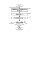
- FIG. 4 is a flowchart showing the processing procedure by the current command generator 42 of the transport system 1 according to the first embodiment.
- FIG. 4 shows the processing procedure executed by the current command generator 42 for each control period.
- step S1 the current command generator 42 calculates a current command bundle I cmdA based on the thrust command for the carriage 17A and the position information of the carriage 17A.
- the current command bundle I cmdA is a group of current commands for generating a thrust that moves the carriage 17A.
- the current command generator 42 generates the current command bundle I cmdA that is a compilation of current commands for all the coils 21 of each transport path unit 11.
- step S2 the current command generator 42 calculates a current command bundle I cmdB based on the thrust command for the carriage 17B and the position information of the carriage 17B.
- the current command bundle I cmdB is a group of current commands for generating a thrust that moves the carriage 17B.
- the current command generator 42 generates the current command bundle I cmdB that is a compilation of current commands for all the coils 21 of each transport path unit 11.
- step S3 the current command generator 42 calculates a current command bundle I cmdC based on the thrust command for the carriage 17C and the position information of the carriage 17C.
- the current command bundle I cmdC is a group of current commands for generating a thrust that moves the carriage 17C.
- the current command generator 42 generates the current command bundle I cmdC that is a compilation of current commands for all the coils 21 of each transport path unit 11.
- step S4 the current command generator 42 uses the current command bundles I cmdA , I cmdB , I cmdC calculated in steps S1-S3 to calculate a current command for each coil 21 of each transport path unit 11.
- the current command generator 42 adds together the current commands for the same coil 21 among the current command bundles I cmdA , I cmdB , I cmdC to calculate a current command I tot for each coil 21 of each transport path unit 11.
- the current command generator 42 determines a current command for each carriage 17 for each coil 21, and generates a current command for each coil 21 by adding together the current commands for each carriage 17 for each coil 21.
- the current command generator 42 generates a current command bundle I cmd that is a compilation of the current commands I tot for all the coils 21 of each transport path unit 11.
- the current command bundle I cmd is a group of current commands for generating thrust to move all the carriages 17A, 17B, and 17C of the transport system 1.
- the current command generator 42 outputs the generated current command bundle I cmd .
- the current command generator 42 ends the processing according to the procedure shown in Fig. 4.
- the current command generator 42 repeats the processing according to the procedure shown in Fig. 4 for each control period.
- the current command for each coil 21 of each transport path unit 11 for generating a thrust to move the carriage 17A will be expressed as "I cmdA _Aa”.
- the "Aa" in "I cmdA _Aa” indicates that this is a current command for the coil 21a of the transport path unit 11A.
- the current command for each coil 21 will be expressed in the same manner as for the coil 21a of the transport path unit 11A.
- FIG. 5 is a diagram showing an example of the relationship between the position of the carriage 17 and the thrust constant of the coil 21 in the first embodiment.
- FIG. 5 shows a graph showing the relationship between the distance x based on the center position of the coil 21 in the traveling direction of the carriage 17 and the thrust constant k(x) of the coil 21.
- the thrust constant k(x) represents the ratio of the thrust force received by the carriage 17 to the current flowing through the coil 21.
- the vertical axis represents the thrust constant k(x) and the horizontal axis represents the distance x.
- the unit of the thrust constant k(x) is N/A.
- the unit of the distance x is arbitrary.
- the center position of the coil 21 refers to the center position of the coil 21 in the traveling direction of the carriage 17.
- the center position of the carriage 17 refers to the center position of the carriage 17 in the traveling direction of the carriage 17.
- Figure 5 shows the bogie 17 when the front end of the bogie 17 in the direction of travel of the bogie 17 coincides with the center position of the coil 21.
- a large thrust can be generated with a small current depending on the relationship between the position of the coil 21 and the phase of the permanent magnet 30.
- the magnitude of the thrust changes depending on the relationship between the position of the coil 21 and the phase of the permanent magnet 30.
- the thrust constant k(x) for each coil 21 of each transport path unit 11 will be expressed as "kAa(x)".
- the "Aa” in “kAa(x)” represents the thrust constant k(x) of the coil 21a of the transport path unit 11A.
- the thrust constant k(x) for each coil 21 will be expressed in the same manner as for the coil 21a of the transport path unit 11A.
- the center position of each coil 21 of each transport path unit 11 will be expressed as "pAa".
- the "Aa" in “pAa” indicates the center position of the coil 21a of the transport path unit 11A.
- the center position of each coil 21 will be expressed in the same manner as for the coil 21a of the transport path unit 11A.
- the current commands IcmdA_Aa , IcmdA_Ab , ..., IcmdA_Hh , IcmdA_Hi for the coils 21 of each transport path unit 11 for generating thrust to move the cart 17A are expressed by the following equations.
- ⁇ A represents the thrust command ⁇ for the cart 17A.
- xA is the distance x from the center position of the coil 21 to the center position of the cart 17A, and represents the actual position of the cart 17A relative to the coil 21.
- I cmdA _ Aa kAa (xA - pAa) x ⁇ A / ⁇ kAa (xA - pAa) 2 + kAb (xA - pAb) 2 + ... + kHh (xA - pHh) 2 + kHi (xA - pHi) 2 ⁇
- I cmdA _ Ab kAb (xA - pAb) x ⁇ A / ⁇ kAa (xA - pAa) 2 + kAb (xA - pAb) 2 + ... + kHh (xA - pHh) 2 + kHi (xA - pHi) 2 ⁇ ...
- I cmdA _ Hh kHh (xA - pHh) x ⁇ A / ⁇ kAa (xA - pAa) 2 + kAb (xA - pAb) 2 + ... + kHh (xA - pHh) 2 + kHi (xA - pHi) 2 ⁇
- I cmdA _ Hi kHi (xA - pHi) x ⁇ A / ⁇ kAa (xA - pAa) 2 + kAb (xA - pAb) 2 + ... + kHh (xA - pHh) 2 + kHi (xA - pHi) 2 ⁇
- the set of current commands I cmdA _Aa, I cmdA _Ab, ..., I cmdA _Hh, I cmdA _Hi obtained by the above formula is a set that minimizes the sum of squares of the currents flowing through the coils 21.
- the above formula can determine the current commands I cmdA _Aa, I cmdA _Ab, ..., I cmdA _Hh, I cmdA _Hi that can minimize the copper loss of the coils 21.
- the current command generator 42 generates a current command bundle I cmdA for the bogie 17A by combining the current commands I cmdA _Aa, I cmdA _Ab, . . . , I cmdA _Hh, and I cmdA _Hi.
- the current command generator 42 calculates the current command bundle I cmdB for the bogie 17B and the current command bundle I cmdC for the bogie 17C in the same manner as the current command bundle I cmdA for the bogie 17A. Note that in the procedure shown in Fig. 4, the calculations are performed in the order of the current command bundle I cmdA , the current command bundle I cmdB , and the current command bundle I cmdC , but the order in which the current command bundles I cmdA , I cmdB , and I cmdC are calculated is arbitrary.
- the current command generator 42 calculates the current command I tot for each coil 21 of each transport path unit 11 using the current command bundles I cmdA , I cmdB , and I cmdC .
- the current command I tot for each coil 21 of each transport path unit 11 will be expressed as "I tot _Aa".
- Aa" in "I tot _Aa” indicates that it is the current command I tot for the coil 21a of the transport path unit 11A.
- the current command I tot for each coil 21 will be expressed in the same manner as for the coil 21a of the transport path unit 11A.
- I tot _Aa I cmdA _Aa + I cmdB _Aa + I cmdC _Aa
- I tot _Ab I cmdA _Ab + I cmdB _Ab + I cmdC _Ab ...
- I tot _Hh I cmdA _Hh + I cmdB _Hh + I cmdC _Hh
- I tot _Hi I cmdA _Hi + I cmdB _Hi + I cmdC _Hi + I cmdC _Hi
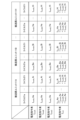
- Fig. 6 is a diagram showing an example of a calculation result of a current command by the transportation system 1 according to the first embodiment.
- Fig. 6 shows an example of the calculation result of the current commands I tot _Aa, I tot _Ab, ..., I tot _Hh, and I tot _Hi by the above-mentioned calculation method.
- the current command I tot _Bd of the coil 21d is calculated as follows.
- the current command generator 42 generates a current command whose current command value is zero for the coil 21 in a position other than the position where the coil 21 can exert a thrust on the bogie 17.
- the current command generator 42 generates current commands I tot _Aa, I tot _Ab, ..., I tot _Hh, and I tot _Hi for all of the coils 21a, 21b, ..., 21i of the transport path units 11A, 11B, ..., 11H.
- the current command generator 42 generates current commands for subjecting all of the multiple coils 21 of each transport path unit 11 to current control in all control cycles when controlling the multiple transport path units 11.
- the current command generator 42 generates a current command bundle I cmd by combining the current commands I tot _Aa, I tot _Ab, ..., I tot _Hh, and I tot _Hi.
- the current command generator 42 outputs the generated current command bundle I cmd to the communication master station 45.
- the communication master station 45 transmits the current commands I tot _Aa, I tot _Ab, ..., I tot _Ai of the current command bundle I cmd to the communication slave station 29 of the transport path unit 11A.
- the communication master station 45 transmits the current commands I tot _Ha, I tot _Hb, ..., I tot _Hi of the current command bundle I cmd to the communication slave station 29 of the transport path unit 11H. In this way, the communication master station 45 transmits current commands to the communication slave station 29 of each transport path unit 11.
- the current command generator 42 of the transport system 1 generates a current command for current control of all of the multiple coils 21 of each transport path unit 11 at each control cycle when controlling the multiple transport path units 11.
- the transport system 1 sends current commands to all coils 21, including not only the coils 21 in positions where they can exert thrust on the cart 17, but also the coils 21 in positions other than those where they can exert thrust on the cart 17.
- the transport system 1 does not require a switch to switch between supplying current to the coils 21 and blocking the current flowing to the coils 21, so the circuit configuration can be simplified.
- the transport system 1 does not require the generation and output of opening and closing commands for the switches in addition to the current commands, so control by a simple program is possible.
- a current command is calculated only for the selected coil 21.
- the current command generator 42 generates current commands uniformly for all coils 21 of each transport path unit 11, so there is no need to select a coil 21 and calculate a current command only for the selected coil 21. This allows the transport system 1 to control each transport path unit 11 using a simple procedure.
- the current command generator 42 generates a current command that sets the current command value to zero for coils 21 in positions other than those where thrust can be exerted on the cart 17. Even if an induced current can occur in coils 21 in positions other than those where thrust can be exerted on the cart 17, the conveying system 1 can adjust the current to zero by canceling out the induced current.
- the conveying system 1 does not need to distinguish between processing cases depending on whether or not the cart 17 is present in a position where thrust can be exerted, and the processing procedure can be simplified.
- the conveying system 1 has the advantage of being able to simplify the circuit configuration and to be controlled through simple processing.
- the current command generator 42 obtains a current command for each bogie 17 for each coil 21, and adds together the current commands for each bogie 17 for each coil 21, thereby generating a current command for each coil 21.
- the current command generator 42 generates a current command for each coil 21 by selecting, for each coil 21, one of the multiple bogies 17 that is closest to the coil 21, and obtaining a current command for applying thrust to the selected bogie 17.
- the same components as those in the first embodiment above are denoted by the same reference numerals, and configurations different from those in the first embodiment will mainly be described.
- FIG. 7 is a diagram showing an example of the configuration of a transport path unit 11 provided in a transport system 1 according to the second embodiment.
- FIG. 7 shows a part of the configuration of the transport path unit 11 and two carts 17A and 17B.
- FIG. 7 shows a case in which two carts 17A and 17B are present in a transport path unit 11A, which is one of the multiple transport path units 11 of the transport system 1.
- the transport system 1 may also have a case in which one cart 17 is present in one transport path unit 11, or a case in which no cart 17 is present in one transport path unit 11.
- the current command generator 42 uses ⁇ A, which is the thrust command ⁇ for the cart 17A, and xA, which is the distance x for the cart 17A, to calculate a current command I tot _Aa for the coil 21a of the transport path unit 11A by the following formula.
- the cart 17 located closest to the center position of the coil 21e in the traveling direction of the cart 17 is the cart 17B.
- the current command generator 42 uses ⁇ B, which is the thrust command ⁇ for the cart 17B, and xB, which is the distance x for the cart 17B, to calculate a current command I tot _Ae for the coil 21e of the transport path unit 11A by the following formula.
- the current command generator 42 uses ⁇ A, which is the thrust command ⁇ for the cart 17A, and xA, which is the distance x for the cart 17A, to calculate a current command I tot _Ad for the coil 21d of the transport path unit 11A by the following formula.
- part of the bogie 17B is also present on the coil 21d.
- the thrust constant of the thrust that the coil 21d can exert on the bogie 17B is approximately zero due to the relationship shown in Fig. 5. Since the magnetic flux generated by the coil 21d hardly contributes to the movement of the bogie 17B, the current command I cmdA _Ad based on ⁇ A and xA for the bogie 17A can be used as the current command I tot _Ad for the coil 21d as it is.
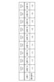
- FIG. 8 is a diagram showing an example of a thrust command used to generate a current command for each coil 21 in the conveyance system 1 according to the second embodiment.
- FIG. 8 shows the carriage 17 located closest to the center position of the coil 21 and the thrust command ⁇ used to generate the current command for each coil 21a-21i in the state shown in FIG. 7.
- the carriage 17 located closest to the center position of the coil 21 is carriage 17A.
- the thrust command ⁇ used to generate the current command for each coil 21a-21d is ⁇ A.
- the carriage 17 located closest to the center position of the coil 21 is carriage 17B.
- the thrust command ⁇ used to generate the current command for each coil 21e-21i is ⁇ B.
- the current command generator 42 generates a current command for each coil 21 by selecting, for each coil 21, one of the multiple carriages 17 that is closest to the coil 21, and determining a current command that applies a thrust to the selected carriage 17.
- the current command generator 42 calculates the current command for each coil 21 of each transport path unit 11B-11H in the same way as the current command for each coil 21 of the transport path unit 11A.
- the current command generator 42 generates a current command bundle I cmd that combines current commands for each coil 21 of each transport path unit 11.
- the current command generator 42 outputs the generated current command bundle I cmd to the communication master station 45.
- the communication master station 45 transmits current commands I tot _Aa, I tot _Ab, ..., I tot _Ai of the current command bundle I cmd to the communication slave station 29 of the transport path unit 11A.
- the communication master station 45 transmits current commands I tot _Ha, I tot _Hb, ..., I tot _Hi of the current command bundle I cmd to the communication slave station 29 of the transport path unit 11H. In this way, the communication master station 45 transmits current commands to the communication slave station 29 of each transport path unit 11.
- the current command generator 42 of the transport system 1 generates a current command for current control of all of the multiple coils 21 of each transport path unit 11 at each control cycle when controlling the multiple transport path units 11. This allows the transport system 1 to have a simplified circuit configuration, and has the advantage of being able to be controlled by simple processing.
- the current command generator 42 selects, for each coil 21, one of the multiple carts 17 that is closest to the coil 21, and determines a current command that applies thrust to the selected cart 17. Because the current command generator 42 calculates a current command corresponding to the selected cart 17 for each coil 21, the amount of calculations can be reduced compared to when current commands corresponding to each of the multiple carts 17 are calculated for each coil 21. This allows the conveyance system 1 to reduce the amount of calculations required for control.
- Embodiment 3 a thrust command is corrected based on a thrust command correction value, and machine learning is applied to the calculation of the thrust command correction value.
- the same components as those in the first or second embodiment are denoted by the same reference numerals, and the configuration different from the first or second embodiment is mainly described.
- each transport path unit 11 the coils 21 are arranged at regular intervals, but the continuity of the arrangement of the coils 21 is interrupted at the connection parts of the transport path units 11 in the transport path 10. For this reason, at the connection parts of the transport path units 11, a cogging torque different from the cogging torque generated between the coils 21 in the transport path unit 11 occurs, and the cogging torque fluctuates. Since the assembly of the transport path units 11 is often performed by the user and assembly errors between the transport path units 11 are likely to occur, it is difficult to predict in advance the correction value for correcting the cogging torque at the connection parts of the transport path units 11. When the correction value is actually obtained after the assembly of the transport path 10 is completed, it is necessary to accurately measure the cogging torque at the connection parts of the transport path units 11, which increases the labor required for assembling the transport path 10.
- the thrust command correction value calculated by machine learning is calculated and the thrust command is corrected, thereby enabling highly accurate correction of the cogging torque and reducing the number of steps required for assembling the conveying path 10.
- the thrust command correction value is a correction value used to correct the thrust command.
- FIG. 9 is a diagram showing an example of the configuration of a track controller 50 provided in the transport system 1 according to the third embodiment.
- the track controller 50 includes a current command generator 42, a position information generator 43, a communication slave station 44, a communication master station 45, a carriage position controller 51, a learning device 52, and a learned model storage unit 53.
- the bogie position controller 51 acquires a position command and position information of each bogie 17.
- the bogie position controller 51 generates a thrust command for each bogie 17 based on the difference between the position command and the position information.
- the bogie position controller 51 also acquires a learned model from the learned model storage unit 53, and determines a thrust command correction value based on the learned model and the position information of each bogie 17.
- the bogie position controller 51 corrects the thrust command using the thrust command correction value, and outputs the corrected thrust command to the current command generator 42.
- the learning device 52 acquires position information and thrust command correction values for each bogie 17.
- the learning device 52 learns thrust command correction values that enable highly accurate correction of the cogging torque.
- the learning device 52 outputs a learned model that is the result of learning.
- the learned model storage unit 53 stores the learned model.
- FIG. 10 is a diagram showing an example of the configuration of the learning device 52 provided in the conveyance system 1 according to the third embodiment.
- the learning device 52 includes a data acquisition unit 61 and a model generation unit 62.
- the data acquisition unit 61 acquires learning data and creates a data set by compiling the learning data.
- the learning data is the position information and thrust command correction value of each carriage 17. That is, the data acquisition unit 61 acquires learning data including the position information and the thrust command correction value.
- the data acquisition unit 61 acquires the position information from the position information generator 43.
- the data acquisition unit 61 acquires the thrust command correction value from the carriage position controller 51.
- the model generation unit 62 generates a trained model using the learning data.
- the model generation unit 62 generates a trained model used to infer a thrust command correction value from position information, based on the learning data.
- the model generation unit 62 outputs the generated trained model.
- the trained model is stored in the trained model storage unit 53.
- the model generation unit 62 may read an already generated trained model from the trained model storage unit 53, and update the trained model by re-learning according to the learning data.
- the learning algorithm used by the model generation unit 62 may be a known algorithm such as supervised learning, unsupervised learning, or reinforcement learning. As an example, a case where reinforcement learning is applied to the learning algorithm used by the model generation unit 62 will be described.
- reinforcement learning an agent acting in an environment observes the current state and determines the action to be taken. The agent obtains rewards from the environment by selecting an action, and learns a strategy that will obtain the most rewards through a series of actions.
- Q-learning and TD-learning are known as representative methods of reinforcement learning.
- the action value table which is a general update formula for the action value function Q(s, a)
- the action value function Q(s, a) represents the action value Q, which is the value of the action of selecting the action "a" in the environment "s".
- s t represents the environment at time “t”.
- a t represents an action at time “t”.
- the action “a t” changes the environment to "s t+1 “.
- r t+1 represents the reward obtained due to the change in the environment.
- ⁇ represents the discount rate.
- ⁇ represents the learning coefficient.
- the position information is the environment “s t “.
- the thrust command correction value is the action "a t “.
- the update formula expressed by equation (1) increases the action value Q if the action value of the best action "a" at time “t+1” is greater than the action value Q of the action "a” executed at time “t”, and decreases the action value Q in the opposite case.
- the action value function Q(s, a) is updated so that the action value Q of the action "a” at time “t” approaches the best action value at time "t+1".
- the best action value in a certain environment is propagated sequentially to the action value in the previous environment.
- the model generation unit 62 has a reward calculation unit 63 and a function update unit 64.
- the reward calculation unit 63 calculates a reward based on the data set.
- the function update unit 64 updates a function for determining a thrust command correction value according to the reward calculated by the reward calculation unit 63.
- the reward calculation unit 63 calculates the reward "r" based on the degree of fluctuation in the speed of the trolley 17.
- the degree of fluctuation in the speed of the trolley 17 is obtained, for example, based on the position information of the trolley 17. For example, if the degree of fluctuation in the speed of the trolley 17 decreases, the reward calculation unit 63 increases the reward "r".
- the reward calculation unit 63 increases the reward "r” by giving it a reward value of "1". Note that the reward value is not limited to "1".
- the reward calculation unit 63 decreases the reward "r”.
- the reward calculation unit 63 decreases the reward "r” by giving it a reward value of "-1". Note that the reward value is not limited to "-1".
- the function update unit 64 updates the function, which is a model for determining the thrust command correction value, according to the reward calculated by the reward calculation unit 63.
- the function can be updated by updating, for example, an action value table according to a data set.
- the action value table is a data set in which any action is associated with its action value and stored in the form of a table.
- the action value function Q(s t , a t ) expressed by the above formula (1) is used as a function for determining the thrust command correction value.
- FIG. 11 is a flowchart showing the processing procedure of the learning device 52 provided in the transport system 1 according to the third embodiment.
- the reinforcement learning method for updating the action value function Q(s, a) will be described with reference to the flowchart in FIG. 11.
- step S11 the learning device 52 acquires the position information and thrust command correction value of each bogie 17 by the data acquisition unit 61. That is, the learning device 52 acquires learning data.
- the data acquisition unit 61 outputs a data set that compiles the learning data to the model generation unit 62.
- step S12 the learning device 52 calculates a reward using the reward calculation unit 63.
- the reward calculation unit 63 calculates a reward for a combination of the position information of each bogie 17 and the thrust command correction value for each bogie 17.
- the reward calculation unit 63 increases or decreases the reward based on the degree of fluctuation in the speed of the bogie 17.
- step S13 the learning device 52 updates the action value function by the function update unit 64.
- the function update unit 64 updates the action value function Q(s, a) based on the reward calculated in step S12.
- the learning device 52 updates the action value function Q(s t , a t ) stored in the learned model storage unit 53.
- step S14 the learning device 52 uses the function update unit 64 to determine whether the action value function Q(s, a) has converged.
- the function update unit 64 determines that the action value function Q(s, a) has converged when the update of the action value function Q(s, a) in step S13 is no longer performed.
- step S14 If it is determined that the action value function Q(s, a) has not converged (step S14, No), the learning device 52 returns the procedure to step S11. On the other hand, if it is determined that the action value function Q(s, a) has converged (step S14, Yes), the learning device 52 ends the processing according to the procedure shown in FIG. 11. Note that the learning device 52 may continue learning by returning the procedure from step S13 to step S11 without making the determination in step S14.
- the learned model storage unit 53 stores the learned model, which is the generated action value function Q(s, a).
- the learning device 52 may perform machine learning using a known learning algorithm other than reinforcement learning, such as a learning algorithm such as deep learning, a neural network, genetic programming, inductive logic programming, or a support vector machine.
- a learning algorithm such as deep learning, a neural network, genetic programming, inductive logic programming, or a support vector machine.
- the learning device 52 shown in Figures 9 and 10 is a device built into the track controller 50.
- the learning device 52 may be a device external to the track controller 50.
- the learning device 52 which is a device external to the track controller 50, constitutes the transportation system 1.
- the learning device 52 may be a device that can be connected to the track controller 50 via a network.
- the learning device 52 may be a device that exists on a cloud server.
- the learning device 52 may learn the relationship between the position information and the thrust command correction value according to a data set created for multiple transport systems 1.
- the learning device 52 may acquire learning data from multiple transport systems 1 used at the same location, or may acquire learning data from multiple transport systems 1 used at different locations.
- the learning data may be collected from multiple transport systems 1 operating independently of each other at multiple locations. After starting to collect learning data from multiple transport systems 1, a new transport system 1 may be added to the targets from which the learning data is collected. Also, after starting to collect learning data from multiple transport systems 1, some of the multiple transport systems 1 may be excluded from the targets from which the learning data is collected.
- the learning device 52 that has learned about one transport system 1 may also learn about other transport systems 1 other than the one in question.
- the learning device 52 that learns about the other transport system 1 can update the learned model by re-learning on the other transport system 1.
- FIG. 12 is a diagram showing an example of the configuration of a carriage position controller 51 provided in the conveyance system 1 according to the third embodiment.
- the carriage position controller 51 includes a thrust command generator 71, a thrust command correction unit 72, a data acquisition unit 73, and an inference unit 74.
- the data acquisition unit 73 and the inference unit 74 function as an inference device that infers a thrust command correction value from the position information of each carriage 17.
- the thrust command generator 71 acquires the position command and the position information of each bogie 17.
- the thrust command generator 71 generates a thrust command for each bogie 17 based on the difference between the position command for each bogie 17 and the position information for each bogie 17.
- the thrust command generator 71 outputs the generated thrust command to the thrust command correction unit 72.
- the data acquisition unit 73 acquires data for inference.
- the data for inference is position information for each of the multiple carts 17 provided in the conveyance system 1.
- the data acquisition unit 73 acquires the position information from the position information generator 43.
- the inference unit 74 reads out the learned model generated by the learning device 52 from the learned model storage unit 53.
- the inference unit 74 infers a thrust command correction value by inputting the data for inference to the learned model.
- the inference unit 74 outputs the thrust command correction value, which is the inference result, to the thrust command correction unit 72.
- the thrust command correction unit 72 corrects the thrust command of each cart 17 using the thrust command correction value.
- the thrust command correction unit 72 outputs the corrected thrust command.
- FIG. 13 is a flowchart showing the processing procedure of the carriage position controller 51 provided in the transport system 1 according to the third embodiment.
- the carriage position controller 51 acquires a position command and position information of each carriage 17 from a thrust command generator 71.
- the thrust command generator 71 generates a thrust command for each carriage 17 based on the position command and the position information.
- step S21 the bogie position controller 51 acquires position information of each bogie 17 by the data acquisition unit 73.
- the data acquisition unit 73 outputs the acquired position information to the inference unit 74.
- step S22 the bogie position controller 51 generates a thrust command correction value by inputting the position information to the learned model by the inference unit 74.
- the inference unit 74 outputs the generated thrust command correction value to the thrust command correction unit 72.
- step S23 the bogie position controller 51 corrects the thrust command using the thrust command correction value by the thrust command correction unit 72.
- the bogie position controller 51 outputs the thrust command corrected by the thrust command correction unit 72.
- the current command generator 42 generates a current command based on the thrust command acquired from the bogie position controller 51 and the position information of each bogie 17.
- the conveying system 1 uses the learning device 52 to learn a thrust command correction value that enables highly accurate correction of the cogging torque.
- the conveying system 1 uses the carriage position controller 51, which includes a data acquisition unit 73 and an inference unit 74, to infer a thrust command correction value that enables highly accurate correction of the cogging torque.
- the conveying system 1 is able to highly accurately correct the cogging torque and reduce the labor required to assemble the conveying path 10.
- the track controllers 20, 50 are realized by a processing circuit.
- the processing circuit may be a circuit in which a processor executes software, or may be a dedicated circuit.
- FIG. 14 is a diagram showing an example configuration of a control circuit 80 according to embodiments 1 to 3.
- the control circuit 80 includes an input unit 81, a processor 82, a memory 83, and an output unit 84.
- the input unit 81 is an interface circuit that receives data input from outside the control circuit 80 and provides it to the processor 82.
- the output unit 84 is an interface circuit that sends data from the processor 82 or memory 83 to outside the control circuit 80.
- the track controllers 20, 50 are realized by software, firmware, or a combination of software and firmware.
- the software or firmware is written as a program and stored in memory 83.
- the processing circuit realizes each function of the track controllers 20, 50 by the processor 82 reading and executing the program stored in the memory 83.
- the processing circuit has a memory 83 for storing a program that will result in the processing of the track controllers 20, 50. It can also be said that these programs cause a computer to execute the procedures and methods of the track controllers 20, 50.
- Processor 82 is a CPU.
- Processor 82 may be a central processing unit, processing unit, arithmetic unit, microprocessor, microcomputer, processor, or DSP.
- Memory 83 may be, for example, a non-volatile or volatile semiconductor memory such as RAM (Random Access Memory), ROM (Read Only Memory), flash memory, EPROM (Erasable Programmable Read Only Memory), EEPROM (registered trademark) (Electrically Erasable Programmable Read Only Memory), a magnetic disk, a flexible disk, an optical disk, a compact disk, a mini disk, or a DVD (Digital Versatile Disc).
- FIG. 14 shows an example of hardware in which the track controllers 20, 50 are realized by a general-purpose processor 82 and memory 83, but the track controllers 20, 50 may also be realized by a dedicated hardware circuit.
- FIG. 15 shows an example of the configuration of a dedicated hardware circuit 85 according to the first to third embodiments.
- the dedicated hardware circuit 85 includes an input unit 81, an output unit 84, and a processing circuit 86.
- the processing circuit 86 is a single circuit, a composite circuit, a programmed processor, a parallel programmed processor, an ASIC (Application Specific Integrated Circuit), an FPGA (Field Programmable Gate Array), or a circuit that combines these.
- Each function of the track controllers 20, 50 may be realized by the processing circuit 86 separately for each function, or each function may be realized collectively by the processing circuit 86.
- the track controllers 20, 50 may be realized by combining the control circuit 80 and the hardware circuit 85.
- the motion controller 19 shown in FIG. 1 is realized by a processing circuit, similar to the track controllers 20 and 50.
- the processing circuit that realizes the motion controller 19 is the control circuit shown in FIG. 14 or a dedicated hardware circuit 85 shown in FIG. 15.
- each component in the conveying system 1 is not limited to those described in the first to third embodiments. All or part of the components of the conveying system 1 may be functionally or physically distributed or integrated in any unit.
- the controller 12 shown in FIG. 1 is not limited to being separated into the motion controller 19 and the track controller 20, and may be realized by a single device.
- Transport system 10. Transport path, 11, 11A-11H. Transport path unit, 12. Controller, 13. DC power supply, 14, 15. Data communication line, 16. DC power supply bus, 17, 17A, 17B, 17C. Cart, 18A, 18B. Arrow, 19. Motion controller, 20, 50. Track controller, 21, 21a-21i. Coil, 22. Inverter circuit, 23. Current sensor, 24. Capacitor, 25. Current controller, 26. Linear scale, 27.
Landscapes
- Engineering & Computer Science (AREA)
- Power Engineering (AREA)
- Physics & Mathematics (AREA)
- Chemical & Material Sciences (AREA)
- Combustion & Propulsion (AREA)
- Electromagnetism (AREA)
- Mechanical Engineering (AREA)
- Artificial Intelligence (AREA)
- Evolutionary Computation (AREA)
- Non-Mechanical Conveyors (AREA)
- Control Of Linear Motors (AREA)
- Control Of Vehicles With Linear Motors And Vehicles That Are Magnetically Levitated (AREA)
Priority Applications (6)
| Application Number | Priority Date | Filing Date | Title |
|---|---|---|---|
| US18/874,611 US12316255B1 (en) | 2022-11-11 | 2022-11-11 | Conveyance system |
| KR1020247040592A KR102763064B1 (ko) | 2022-11-11 | 2022-11-11 | 반송 시스템 |
| CN202280096350.5A CN119233936B (zh) | 2022-11-11 | 2022-11-11 | 输送系统 |
| JP2023532838A JP7415085B1 (ja) | 2022-11-11 | 2022-11-11 | 搬送システム |
| DE112022007181.8T DE112022007181T5 (de) | 2022-11-11 | 2022-11-11 | Fördersystem |
| PCT/JP2022/042087 WO2024100885A1 (ja) | 2022-11-11 | 2022-11-11 | 搬送システム |
Applications Claiming Priority (1)
| Application Number | Priority Date | Filing Date | Title |
|---|---|---|---|
| PCT/JP2022/042087 WO2024100885A1 (ja) | 2022-11-11 | 2022-11-11 | 搬送システム |
Publications (1)
| Publication Number | Publication Date |
|---|---|
| WO2024100885A1 true WO2024100885A1 (ja) | 2024-05-16 |
Family
ID=89534358
Family Applications (1)
| Application Number | Title | Priority Date | Filing Date |
|---|---|---|---|
| PCT/JP2022/042087 Ceased WO2024100885A1 (ja) | 2022-11-11 | 2022-11-11 | 搬送システム |
Country Status (6)
| Country | Link |
|---|---|
| US (1) | US12316255B1 (https=) |
| JP (1) | JP7415085B1 (https=) |
| KR (1) | KR102763064B1 (https=) |
| CN (1) | CN119233936B (https=) |
| DE (1) | DE112022007181T5 (https=) |
| WO (1) | WO2024100885A1 (https=) |
Cited By (1)
| Publication number | Priority date | Publication date | Assignee | Title |
|---|---|---|---|---|
| JP7721039B1 (ja) * | 2024-11-27 | 2025-08-08 | 三菱電機株式会社 | 搬送システム |
Citations (4)
| Publication number | Priority date | Publication date | Assignee | Title |
|---|---|---|---|---|
| JPH0919178A (ja) * | 1995-06-27 | 1997-01-17 | Canon Inc | リニア・モータ装置 |
| JPH11205910A (ja) * | 1998-01-07 | 1999-07-30 | Nkk Corp | リニア式台車型搬送装置 |
| JP2000191140A (ja) * | 1998-12-26 | 2000-07-11 | Minebea Co Ltd | リニアモ―タを用いた搬送システム |
| JP2021126002A (ja) * | 2020-02-07 | 2021-08-30 | キヤノン株式会社 | 搬送装置および物品の製造方法 |
Family Cites Families (14)
| Publication number | Priority date | Publication date | Assignee | Title |
|---|---|---|---|---|
| US6191507B1 (en) * | 1997-05-02 | 2001-02-20 | Ats Automation Tooling Systems Inc. | Modular conveyor system having multiple moving elements under independent control |
| US6240335B1 (en) * | 1998-12-14 | 2001-05-29 | Palo Alto Technologies, Inc. | Distributed control system architecture and method for a material transport system |
| JP2004159385A (ja) | 2002-11-01 | 2004-06-03 | Canon Inc | リニアモータ駆動回路 |
| JP5305257B2 (ja) * | 2011-06-15 | 2013-10-02 | 株式会社安川電機 | 搬送システム |
| DE102013209362A1 (de) * | 2013-05-21 | 2014-11-27 | Krones Ag | Überwachung und Steuerung einer Transportvorrichtung für Behälter |
| JP6504795B2 (ja) | 2014-11-19 | 2019-04-24 | 学校法人 工学院大学 | トルクリップル抑制装置及びトルクリップル抑制方法 |
| US9540190B2 (en) * | 2015-04-09 | 2017-01-10 | Amazon Technologies, Inc. | Methods and apparatus for controlling movement of receptacles |
| JP6704705B2 (ja) | 2015-10-22 | 2020-06-03 | キヤノン株式会社 | 可動磁石型リニアモータ制御システム及びその制御方法 |
| EP3173186A1 (de) * | 2015-11-24 | 2017-05-31 | Siemens Aktiengesellschaft | Maschinenstation mit einem linearantrieb, anlage und verfahren zur bearbeitung eines bearbeitungsgutes |
| US11165372B2 (en) * | 2017-09-13 | 2021-11-02 | Rockwell Automation Technologies, Inc. | Method and apparatus to characterize loads in a linear synchronous motor system |
| US11539244B2 (en) * | 2017-09-28 | 2022-12-27 | Rockwell Automation Technologies, Inc. | Method and apparatus for data transmission over an inductive link for an independent cart system |
| US10608469B2 (en) * | 2017-09-28 | 2020-03-31 | Rockwell Automation Technologies, Inc. | Method and apparatus for power transfer to an independent moving cart during travel along a track |
| JP7323410B2 (ja) * | 2019-10-01 | 2023-08-08 | 株式会社日立ハイテク | 搬送装置、および分析システム |
| US20240317513A1 (en) * | 2021-08-05 | 2024-09-26 | Tetra Laval Holdings & Finance S.A. | A linear motor system, corresponding forming assembly and method |
-
2022
- 2022-11-11 CN CN202280096350.5A patent/CN119233936B/zh active Active
- 2022-11-11 KR KR1020247040592A patent/KR102763064B1/ko active Active
- 2022-11-11 DE DE112022007181.8T patent/DE112022007181T5/de active Granted
- 2022-11-11 WO PCT/JP2022/042087 patent/WO2024100885A1/ja not_active Ceased
- 2022-11-11 US US18/874,611 patent/US12316255B1/en active Active
- 2022-11-11 JP JP2023532838A patent/JP7415085B1/ja active Active
Patent Citations (4)
| Publication number | Priority date | Publication date | Assignee | Title |
|---|---|---|---|---|
| JPH0919178A (ja) * | 1995-06-27 | 1997-01-17 | Canon Inc | リニア・モータ装置 |
| JPH11205910A (ja) * | 1998-01-07 | 1999-07-30 | Nkk Corp | リニア式台車型搬送装置 |
| JP2000191140A (ja) * | 1998-12-26 | 2000-07-11 | Minebea Co Ltd | リニアモ―タを用いた搬送システム |
| JP2021126002A (ja) * | 2020-02-07 | 2021-08-30 | キヤノン株式会社 | 搬送装置および物品の製造方法 |
Cited By (1)
| Publication number | Priority date | Publication date | Assignee | Title |
|---|---|---|---|---|
| JP7721039B1 (ja) * | 2024-11-27 | 2025-08-08 | 三菱電機株式会社 | 搬送システム |
Also Published As
| Publication number | Publication date |
|---|---|
| US20250167710A1 (en) | 2025-05-22 |
| CN119233936A (zh) | 2024-12-31 |
| KR102763064B1 (ko) | 2025-02-05 |
| US12316255B1 (en) | 2025-05-27 |
| KR20240177748A (ko) | 2024-12-27 |
| JPWO2024100885A1 (https=) | 2024-05-16 |
| DE112022007181T5 (de) | 2025-04-24 |
| CN119233936B (zh) | 2025-08-22 |
| JP7415085B1 (ja) | 2024-01-16 |
Similar Documents
| Publication | Publication Date | Title |
|---|---|---|
| JP7258266B1 (ja) | 搬送システム | |
| CN107453678B (zh) | 用于运行长定子直线电机的方法、系统和运输装置 | |
| JP6704705B2 (ja) | 可動磁石型リニアモータ制御システム及びその制御方法 | |
| JP2013025639A (ja) | 移動体システムと移動体の走行制御方法 | |
| JP6733170B2 (ja) | リニアモータシステム | |
| US20210261351A1 (en) | Independent Mover Transport System And Method Of Extending Range Of Operations In An Independent Mover Transport System | |
| KR102763064B1 (ko) | 반송 시스템 | |
| US20180090254A1 (en) | Method and Apparatus for Interleaved Switching of Track Segments in a Motion Control System | |
| JP7258265B1 (ja) | 搬送システム | |
| US20170054397A1 (en) | Mobile body, mobile body system, and position detecting method for mobile body | |
| TW200524815A (en) | Carriage system | |
| US20250270053A1 (en) | Transport system | |
| US20260012120A1 (en) | Transfer system | |
| JP7665874B1 (ja) | 搬送システム | |
| JP2013024779A (ja) | 磁気式変位センサと変位検出方法 | |
| JP7682421B1 (ja) | 制御装置及び搬送システム | |
| JPWO2020115786A1 (ja) | 搬送装置 | |
| JP7721039B1 (ja) | 搬送システム | |
| JP5348107B2 (ja) | 搬送車 | |
| JPS63296111A (ja) | 走行ロボットのホ−ムポジション設置方式 |
Legal Events
| Date | Code | Title | Description |
|---|---|---|---|
| WWE | Wipo information: entry into national phase |
Ref document number: 2023532838 Country of ref document: JP |
|
| 121 | Ep: the epo has been informed by wipo that ep was designated in this application |
Ref document number: 22965209 Country of ref document: EP Kind code of ref document: A1 |
|
| WWE | Wipo information: entry into national phase |
Ref document number: 202280096350.5 Country of ref document: CN |
|
| ENP | Entry into the national phase |
Ref document number: 20247040592 Country of ref document: KR Kind code of ref document: A |
|
| WWE | Wipo information: entry into national phase |
Ref document number: 1020247040592 Country of ref document: KR |
|
| WWE | Wipo information: entry into national phase |
Ref document number: 18874611 Country of ref document: US |
|
| WWE | Wipo information: entry into national phase |
Ref document number: 112022007181 Country of ref document: DE |
|
| WWP | Wipo information: published in national office |
Ref document number: 202280096350.5 Country of ref document: CN |
|
| WWP | Wipo information: published in national office |
Ref document number: 112022007181 Country of ref document: DE |
|
| WWP | Wipo information: published in national office |
Ref document number: 18874611 Country of ref document: US |
|
| WWG | Wipo information: grant in national office |
Ref document number: 18874611 Country of ref document: US |
|
| WWG | Wipo information: grant in national office |
Ref document number: 202280096350.5 Country of ref document: CN |
|
| 122 | Ep: pct application non-entry in european phase |
Ref document number: 22965209 Country of ref document: EP Kind code of ref document: A1 |