WO2024100855A1 - 表示制御装置及び表示制御方法 - Google Patents
表示制御装置及び表示制御方法 Download PDFInfo
- Publication number
- WO2024100855A1 WO2024100855A1 PCT/JP2022/041969 JP2022041969W WO2024100855A1 WO 2024100855 A1 WO2024100855 A1 WO 2024100855A1 JP 2022041969 W JP2022041969 W JP 2022041969W WO 2024100855 A1 WO2024100855 A1 WO 2024100855A1
- Authority
- WO
- WIPO (PCT)
- Prior art keywords
- obstacle
- vehicle
- display
- controller
- driving
- Prior art date
- Legal status (The legal status is an assumption and is not a legal conclusion. Google has not performed a legal analysis and makes no representation as to the accuracy of the status listed.)
- Ceased
Links
Images





Classifications
-
- B—PERFORMING OPERATIONS; TRANSPORTING
- B60—VEHICLES IN GENERAL
- B60W—CONJOINT CONTROL OF VEHICLE SUB-UNITS OF DIFFERENT TYPE OR DIFFERENT FUNCTION; CONTROL SYSTEMS SPECIALLY ADAPTED FOR HYBRID VEHICLES; ROAD VEHICLE DRIVE CONTROL SYSTEMS FOR PURPOSES NOT RELATED TO THE CONTROL OF A PARTICULAR SUB-UNIT
- B60W50/00—Details of control systems for road vehicle drive control not related to the control of a particular sub-unit, e.g. process diagnostic or vehicle driver interfaces
- B60W50/08—Interaction between the driver and the control system
- B60W50/14—Means for informing the driver, warning the driver or prompting a driver intervention
-
- B—PERFORMING OPERATIONS; TRANSPORTING
- B60—VEHICLES IN GENERAL
- B60W—CONJOINT CONTROL OF VEHICLE SUB-UNITS OF DIFFERENT TYPE OR DIFFERENT FUNCTION; CONTROL SYSTEMS SPECIALLY ADAPTED FOR HYBRID VEHICLES; ROAD VEHICLE DRIVE CONTROL SYSTEMS FOR PURPOSES NOT RELATED TO THE CONTROL OF A PARTICULAR SUB-UNIT
- B60W30/00—Purposes of road vehicle drive control systems not related to the control of a particular sub-unit, e.g. of systems using conjoint control of vehicle sub-units
- B60W30/08—Active safety systems predicting or avoiding probable or impending collision or attempting to minimise its consequences
- B60W30/095—Predicting travel path or likelihood of collision
- B60W30/0956—Predicting travel path or likelihood of collision the prediction being responsive to traffic or environmental parameters
-
- B—PERFORMING OPERATIONS; TRANSPORTING
- B60—VEHICLES IN GENERAL
- B60W—CONJOINT CONTROL OF VEHICLE SUB-UNITS OF DIFFERENT TYPE OR DIFFERENT FUNCTION; CONTROL SYSTEMS SPECIALLY ADAPTED FOR HYBRID VEHICLES; ROAD VEHICLE DRIVE CONTROL SYSTEMS FOR PURPOSES NOT RELATED TO THE CONTROL OF A PARTICULAR SUB-UNIT
- B60W60/00—Drive control systems specially adapted for autonomous road vehicles
- B60W60/001—Planning or execution of driving tasks
-
- G—PHYSICS
- G08—SIGNALLING
- G08G—TRAFFIC CONTROL SYSTEMS
- G08G1/00—Traffic control systems for road vehicles
- G08G1/16—Anti-collision systems
- G08G1/166—Anti-collision systems for active traffic, e.g. moving vehicles, pedestrians, bikes
-
- B—PERFORMING OPERATIONS; TRANSPORTING
- B60—VEHICLES IN GENERAL
- B60W—CONJOINT CONTROL OF VEHICLE SUB-UNITS OF DIFFERENT TYPE OR DIFFERENT FUNCTION; CONTROL SYSTEMS SPECIALLY ADAPTED FOR HYBRID VEHICLES; ROAD VEHICLE DRIVE CONTROL SYSTEMS FOR PURPOSES NOT RELATED TO THE CONTROL OF A PARTICULAR SUB-UNIT
- B60W50/00—Details of control systems for road vehicle drive control not related to the control of a particular sub-unit, e.g. process diagnostic or vehicle driver interfaces
- B60W50/08—Interaction between the driver and the control system
- B60W50/14—Means for informing the driver, warning the driver or prompting a driver intervention
- B60W2050/146—Display means
Definitions
- the present invention relates to a display control device and a display control method.
- a vehicle display device that displays the stopped state of a vehicle with an autonomous driving function is known (Patent Document 1).
- Patent Document 1 A vehicle display device that displays the stopped state of a vehicle with an autonomous driving function.
- the vehicle display device described in Patent Document 1 displays a stop sign to stop the vehicle, but does not display obstacles on or around the driving route, which makes it difficult to intuitively grasp obstacles that exist around the vehicle and that may affect the driving of the vehicle.
- the problem that this invention aims to solve is to provide a display control device and a display control method that allow the driver to intuitively grasp obstacles that affect the driving of the vehicle.
- the present invention solves the above problems by identifying obstacles from information about the surroundings of the vehicle, displaying on a display device the obstacles and driving route located within a predetermined enlarged range obtained by expanding the driving route of the vehicle in the width direction, and displaying the first obstacle on the display device when a first obstacle that is approaching the driving route or has the potential to approach the driving route is located outside the enlarged range, and by lowering the display emphasis of the second obstacle below the display emphasis of obstacles other than the second obstacle or not displaying the second obstacle on the display device when a second obstacle that is away from the driving route or has the potential to leave the driving route is located within the enlarged range.
- the present invention allows the driver to intuitively grasp obstacles that affect the vehicle's travel.
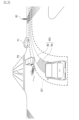
- FIG. 1 is a block diagram showing an example of a driving assistance device according to an embodiment of the present invention
- FIG. 2 is a block diagram showing an example of a controller etc. according to the present embodiment.
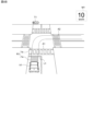
- FIG. 2 is a schematic diagram showing a scene in which the host vehicle approaches an intersection;
- 4 is an example of a display image according to the present embodiment.
- 4 is an example of a display image according to the present embodiment.
- FIG. 4 is a diagram for explaining a display image according to the embodiment. 4 is an example of a display image according to the present embodiment.
- 5 is a flowchart showing a control process related to the display of a travel route and obstacles.
- 7 is a flowchart showing a sub-flow of step S40 shown in FIG. 6.
- FIG. 1 is a block diagram showing an example of a driving assistance device 1 according to this embodiment.
- the driving assistance device 1 performs automatic driving control of a vehicle equipped with the driving assistance device 1 (hereinafter referred to as the "own vehicle") based on the driving environment around the vehicle.
- the own vehicle can be driven under automatic driving control by the driving assistance device 1 or manually driven by the driver.
- the self-driving control is not limited to completely autonomous control led by the system, and may be so-called driving assistance control in which part of the drive system, such as the steering, is operated by the driver.
- the driving assistance device 1 comprises a group of surrounding environment sensors 10, a positioning device 11, a high-precision map storage unit 12, a group of vehicle sensors 20, a controller 30, a display device 31, and a group of vehicle control actuators 40.
- the controller 30 is a display control device according to this embodiment of the present invention.
- the display device does not necessarily have to be mounted on the driving assistance device. In other words, the display device is applicable not only to automated driving systems, but also to manual driving systems.
- the surrounding environment sensor group 10 is a group of sensors for detecting objects around the vehicle.
- Objects include obstacles such as pedestrians, bicycles, vehicles, and motorcycles, as well as traffic-related features such as lane boundaries, road markings, and road signs.
- the surrounding environment sensor group 10 includes a distance measuring device 13, a camera 14, and a communication device 15, and is installed on the vehicle.
- the surrounding environment sensor group 10 outputs information on the surrounding conditions of the vehicle to the controller 30.
- the information on the surrounding conditions of the vehicle includes information detected by the distance measuring device 13 and/or the camera, or information received by the communication device 15.
- An object is detected, for example, by the distance measuring device 13, the camera 14, and the communication device 15.
- the distance measuring device 13 is a device for calculating the relative position, relative distance, relative speed, etc. of an object with respect to the vehicle, and is, for example, a radar device such as a laser radar, or a sonar.
- Camera 14 is a device that recognizes objects around the vehicle using images.
- Information about objects recognized by camera 14 includes, for example, the type of object, the color of the object (such as the color of a traffic light, such as blue, yellow, or red), the position of the object, and the relative distance between the vehicle and the object.
- the distance measuring device 13 and the camera 14 output information on the surroundings of the vehicle to the controller 30 at a predetermined time interval.
- the controller 30 can calculate the position of the object from the relative positions (distance and direction) of the vehicle and the object detected by the distance measuring device 13 and/or the camera 14.
- the controller 30 may calculate the position of the object by adding high-precision map information stored in the high-precision map memory unit 12 to the information on the surroundings of the vehicle obtained from the distance measuring device 13 and/or the camera 14.
- the communication device 15 is a device that recognizes objects around the vehicle by wireless communication, and is, for example, a device that connects to the Internet.
- the communication device 15 may also be a device that supports communication standards for vehicle-to-vehicle communication with other vehicles and road-to-vehicle communication with roadside devices.
- the communication device 15 may perform road-to-vehicle communication with roadside devices (e.g., traffic lights) around the vehicle, and receive information such as the color of the traffic lights from the roadside devices.
- the detection results detected by the communication device 15 are output to the controller 30 as information on the surrounding conditions of the vehicle.
- the positioning device 11 is a device that measures the current position of the vehicle, and is, for example, a Global Positioning System (GPS) receiver.
- GPS Global Positioning System
- the positioning device 11 receives satellite signals from a satellite positioning system at a predetermined time interval, and measures the current position of the vehicle. The measurement results by the positioning device 11 are output to the controller 30.
- GPS Global Positioning System
- the high-precision map information stored in the high-precision map storage unit 12 is map information with higher accuracy than conventional navigation map information, and includes lane-by-lane information that is more detailed than road-by-road information.
- the high-precision map information includes lane node information indicating reference points such as intersections on lane reference lines (e.g., center lines) and lane link information indicating the section state of lanes between lane nodes, as lane-by-lane information.
- the high-precision map information also includes lane boundary information including the boundary between the lane on which the vehicle is traveling and the rest.
- the lane on which the vehicle is traveling is the road on which the vehicle is traveling, and the form of the lane is not particularly limited.
- the lane boundaries exist on both the left and right sides of the traveling direction of the vehicle.
- the form of the lane boundary is not particularly limited, and examples include road markings (lane boundary lines, center lines, etc.) and road structures (median strips, guard rails, curbs, side walls of tunnels or expressways, etc.).
- lane boundaries are set in advance in the high-precision map information for points where the lane boundary cannot be clearly identified (e.g., within intersections).
- the predefined lane boundaries are imaginary lane boundaries and are not actual road markings or road structures.
- high-precision map information includes imaginary lane boundaries within intersections for each of the following cases: going straight, turning left, and turning right.
- the vehicle sensor group 20 includes sensors that detect the driving state of the vehicle and sensors that detect driving operations by the driver.
- the sensors that detect the driving state of the vehicle include a vehicle speed sensor 21, an acceleration sensor 22, and a gyro sensor 23.
- the sensors that detect driving operations include a steering angle sensor 24, an accelerator sensor 25, and a brake sensor 26.
- the vehicle speed sensor 21 detects the wheel speed of the vehicle and calculates the vehicle speed based on the wheel speed.
- the acceleration sensor 22 detects the acceleration in the front-rear direction, the width direction, and the up-down direction of the vehicle.
- the gyro sensor 23 detects the angular velocity of the rotation angle of the vehicle around three axes including the roll axis, pitch axis, and yaw axis.
- the steering angle sensor 24 detects the current steering angle, which is the current rotation angle (steering operation amount) of the steering wheel, which is the steering operator.
- the accelerator sensor 25 detects the accelerator operation amount (accelerator opening) by the driver.
- the brake sensor 26 detects the brake operation amount by the driver.
- Information on the vehicle's speed, acceleration, angular velocity, steering angle, accelerator operation amount (accelerator opening), and brake operation amount detected by each sensor in the vehicle sensor group 20 is collectively referred to as "vehicle information.”
- the vehicle sensor group 20 outputs the vehicle information to the controller 30.
- the vehicle control actuator group 40 is a group of on-board computers such as an electronic control unit (ECU), and controls on-board equipment that governs the driving of the host vehicle.
- the vehicle control actuator group 40 includes a steering actuator 41 that controls the steering operation of the host vehicle, an accelerator opening actuator 42 that controls the driving speed of the host vehicle, and a brake control actuator 43.
- the steering actuator 41, accelerator opening actuator 42, and brake control actuator 43 autonomously control the operation of the steering device, drive device, and braking device in response to control signals input from the controller 30. This allows the host vehicle to drive autonomously along the driving route generated by the controller 30.
- the steering actuator 41 controls the steering actuator that controls the steered wheels according to the steering angle of the steering wheel (so-called handle).
- the accelerator opening actuator 42 controls the accelerator opening of the vehicle by controlling the electric motor and/or internal combustion engine that are the driving sources for driving the vehicle, the power transmission device including the drive shaft and automatic transmission that transmit the output from these driving sources to the drive wheels, and the drive device that controls the power transmission device.
- the brake control actuator 43 also controls the braking device that brakes the wheels of the vehicle. In the autonomous driving mode, the controller 30 inputs a control signal corresponding to the target vehicle speed to the accelerator opening actuator 42 and the brake control actuator 43.
- the steering actuator 41 receives, for example, a control signal from the controller 30 in response to the steering angle detected by the vehicle sensor group 20.
- the accelerator opening actuator 42 receives, for example, a control signal from the controller 30 in response to the accelerator opening detected by the vehicle sensor group 20.
- the brake control actuator 43 receives, for example, a control signal in response to the amount of brake operation detected by the vehicle sensor group 20.
- the controller 30 is a processing circuit such as an electronic control unit (ECU) that controls the driving of the vehicle.
- the controller 30 is also a processing circuit such as an electronic control unit (ECU) that controls display to present the surrounding environment (surrounding conditions) of the vehicle to the occupants.
- the controller 30 includes a processor 32 and peripheral components such as a storage device 33.
- the processor 32 includes a processing circuit for operating a program stored in the storage device 33.
- the controller 30 can switch between an automatic driving mode in which the vehicle is driven by autonomous driving control, and a manual driving mode in which the vehicle is driven manually by the driver.
- the controller 30 is programmed to comply with traffic laws when driving the vehicle by autonomous driving control.
- the controller 30 calculates a driving route for the host vehicle and drives the vehicle control actuator group 40 so that the host vehicle travels along the driving route.
- the controller 30 realizes autonomous control of the steering and speed of the host vehicle by calculating the control amount and outputting the control signal to the vehicle control actuator group 40 at a predetermined time interval.
- the controller 30 also generates a display image (human-machine interface (HMI) image) to present the surrounding environment (surrounding conditions) of the vehicle to the viewer of the display device 31 based on the surrounding environment information detected by the surrounding environment sensor group 10.
- HMI human-machine interface
- FIG. 3 shows an example of a scene in which the vehicle 100 is traveling autonomously along a travel route 105.
- the vehicle 100 enters an intersection just before the intersection and then turns right at the intersection.
- a stop line 101 and a pedestrian crossing 102 exist just before the intersection, and a traffic light 103 is installed at the back of the intersection.
- a pedestrian crossing 104 exists beyond where the vehicle 100 has made the right turn.
- the controller 30 generates a display image for displaying to the occupant the surrounding conditions of the host vehicle 100 shown in FIG. 3.
- the display image shows the road surface ahead of the host vehicle 100, including the lane the host vehicle 100 is traveling in and the intersection shown in FIG. 3.
- the display image may be a bird's-eye view image of the surroundings of the host vehicle 100, including the area ahead of the host vehicle 100, from a virtual viewpoint located diagonally above and behind the host vehicle 100.
- the display image may be a virtual image such as a computer graphics (CG) image, or may be an image captured by the camera 14.
- FIG. 4A is an example of a display image according to this embodiment.
- the display image includes a display (own vehicle icon) V1 simulating the host vehicle 100 in FIG. 3, a display (crosswalk icon) A1 simulating the crosswalk 102 in FIG. 3, a display (traffic light icon) T1 simulating the traffic light 103 in FIG. 3, a display (crosswalk icon) A2 simulating the crosswalk 104 in FIG. 3, and a current vehicle speed display M1 of the host vehicle 100.
- the display image also includes a display (travel route image) R0 simulating the travel route 105 of the host vehicle 100 shown in FIG. 3.
- the travel route image R0 is an image having a width approximately equal to the vehicle width of the host vehicle V1, and its shape corresponds to the travel route 105 shown in FIG. 3.
- the travel route image R0 may be an image in which a specific color is superimposed to distinguish it from other displays.
- an icon representing the obstacle e.g., an icon of a preceding vehicle, an oncoming vehicle, a parked vehicle, a pedestrian, a motorcycle, a bicycle, a pedestrian, etc. is displayed on the display device 31.
- the controller 30 shown in FIG. 1 displays the generated display image on the display device 31. Furthermore, the controller 30 performs safety checks necessary for the host vehicle to travel autonomously along the travel route based on the surrounding environment information detected by the surrounding environment sensor group 10 and the high-precision map information stored in the high-precision map storage unit 12, and displays on the display device 31 a display image including a travel route image that distinguishes between areas on the vehicle's travel route where safety checks have been completed and other areas (the travel route image after safety checks have been completed will be described later).
- the display device 31 is mounted on the vehicle and is, for example, a display of a navigation device, a display arranged on a meter panel, or a head-up display (HUD) device.
- a display of a navigation device for example, a display of a navigation device, a display arranged on a meter panel, or a head-up display (HUD) device.
- HUD head-up display
- FIG. 2 is a block diagram showing an example of a controller according to this embodiment.
- the controller 30 includes a vehicle speed acquisition unit 50, a surrounding information acquisition unit 51, a stop determination position acquisition unit 52, a vehicle position calculation unit 53, an approach determination unit 54, a stop possibility calculation unit 55, a driving path calculation unit 56, a driving path acquisition unit 57, an HMI drawing unit 58, an obstacle identification unit 59, and a display image generation unit 60.
- the functions of each block shown in FIG. 2 are realized by the processor 32 of the controller 30 executing a computer program stored in the storage device 33.
- the vehicle speed acquisition unit 50 acquires the vehicle speed of the vehicle detected by the vehicle speed sensor 21.
- the surrounding information acquisition unit 51 acquires information on the surrounding conditions of the vehicle (vehicle surrounding information) from the distance measurement device 13 and the camera 14.
- the vehicle surrounding information includes signal information of the traffic lights ahead of the vehicle, information on other vehicles around the vehicle such as preceding vehicles and oncoming vehicles, pedestrian information, etc.
- the surrounding information acquisition unit 51 may also acquire the vehicle surrounding information from the communication device 15.
- the stop judgment position acquisition unit 52 acquires stop judgment positions existing on the vehicle's travel route from the high-precision map information stored in the high-precision map storage unit 12.
- a stop judgment position is a position where a safety check may be performed while the vehicle is stopped. Stop judgment positions include positions where the vehicle must stop and positions where the possibility of the vehicle stopping changes depending on the conditions around the vehicle. Stop judgment positions include at least one of an intersection, a crosswalk, a junction, a traffic light, and a stop line.
- the host vehicle 100 when the traffic light 103 is red, the host vehicle 100 must stop before the stop line 101.
- the host vehicle 100 must stop within the intersection depending on whether there is an oncoming vehicle. For example, when there is an oncoming vehicle traveling straight, the oncoming vehicle's straight travel has priority over the host vehicle 100 turning right, so the host vehicle 100 must stop within the intersection.
- the host vehicle 100 must stop before the crosswalk 104 depending on whether there is a pedestrian crossing the crosswalk 104.
- the display control device and display control method according to this embodiment show the complex and wide-ranging situations as described above in a driving path image and display it on the display device 31, thereby intuitively conveying information such as the possibility of the host vehicle stopping and the stopping position of the host vehicle to the viewer through visual contact. This makes it possible to increase the number of locations and surrounding environments where the safety confirmation situation during autonomous driving can be appropriately conveyed to the viewer. Furthermore, the display control device and display control method according to this embodiment can intuitively convey the presence of an obstacle that will affect the driving of the host vehicle to the viewer by displaying the obstacle on the display device 31 according to the relationship between the driving path of the host vehicle and the obstacle around the host vehicle.
- the stop judgment position acquisition unit 52 acquires a stop judgment position existing on the driving route from the high-precision map information, for example, at the timing when the driving route of the vehicle is input from the driving route acquisition unit 57. Note that in the case of a stop judgment position where other stop judgment positions such as a crosswalk or a traffic light exist in the surrounding area, such as an intersection, the stop judgment position acquisition unit 52 may acquire each stop judgment position from the high-precision map information. In the example of FIG. 3, the stop judgment position acquisition unit 52 may acquire the positions (position coordinates) of the stop line 101, the crosswalk 102, the traffic light 103, and the crosswalk 104 in addition to the reference point of the intersection (lane node information) from the high-precision map information.
- the vehicle position calculation unit 53 detects the current position of the vehicle on the high-precision map based on the positioning information obtained by the positioning device 11 and the high-precision map information stored in the high-precision map storage unit 12.
- the approach determination unit 54 determines whether or not the host vehicle is approaching the stop determination position based on the stop determination position acquired by the stop determination position acquisition unit 52, the current position of the host vehicle detected by the host vehicle position calculation unit 53, and the host vehicle's travel route input from the travel route acquisition unit 57. In the example of FIG. 3, the approach determination unit 54 determines whether or not the host vehicle 100 is approaching an intersection.
- the approach determination unit 54 calculates the distance between the stop judgment position and the current position of the vehicle, and determines that the vehicle is approaching the stop judgment position if the calculated distance is less than a predetermined threshold. On the other hand, the approach determination unit 54 determines that the vehicle is not approaching the stop judgment position if the distance between the stop judgment position and the current position of the vehicle is equal to or greater than the predetermined threshold.
- the predetermined threshold is the distance at which the vehicle can stop before the stop judgment position after starting to decelerate.
- the stop possibility calculation unit 55 performs a safety check necessary for the host vehicle to travel the travel path by autonomous driving, based on the surrounding environment information detected by the surrounding environment sensor group 10. As one of the safety checks, the stop possibility calculation unit 55 determines whether or not to stop the host vehicle at the stop determination position. When the stop possibility calculation unit 55 determines that it is not necessary for the host vehicle to stop at the stop determination position, that is, when it determines that the host vehicle can pass through the stop determination position, it determines that the safety check for the host vehicle passing through the stop judgment position has been completed.
- stop possibility calculation unit 55 determines that it is necessary for the host vehicle to stop at the stop judgment position, that is, when it determines that the host vehicle cannot pass through the stop judgment position, it determines that the safety check for the host vehicle passing through the stop judgment position has not been completed.
- Stopping factors include road structures such as stop signs and traffic lights indicating no proceeding, and moving objects that cross the host vehicle's travel route.
- stopping factors are described using traffic lights (an example of a road structure), pedestrians, and oncoming vehicles (an example of a moving object that crosses the travel route). Stopping factors are also referred to as factors that prevent the host vehicle from traveling autonomously along the travel route, i.e. factors that impede the autonomous travel of the host vehicle.
- the stop possibility calculation unit 55 When performing a safety check for multiple stopping factors around the vehicle, the stop possibility calculation unit 55 performs a safety check for each stopping factor.
- stopping factors that cause the vehicle 100 to stop include a traffic light 103, an oncoming vehicle (not shown) going straight through an intersection, and a pedestrian crossing the crosswalk 104. Examples of safety checks for each stopping factor will be described below.
- the stopping possibility calculation unit 55 performs safety checks for traffic signals based on traffic light information, safety checks for pedestrians based on pedestrian information, and safety checks for oncoming vehicles based on oncoming vehicle information.
- the stop possibility calculation unit 55 determines whether or not it is necessary to stop the host vehicle at the stop line, depending on the color of the traffic light at the time when the approach determination unit 54 determines that the host vehicle is approaching an intersection as a safety check for the traffic lights.
- the stop possibility calculation unit 55 determines that it is necessary to stop the host vehicle at the stop line.
- the stop possibility calculation unit 55 determines that it is not necessary to stop the host vehicle at the stop line. Note that when the traffic light indicates a transition from proceeding permitted to proceeding prohibited (when the traffic light is yellow), the stop possibility calculation unit 55 determines that it is necessary to stop the host vehicle at the stop line.
- the stop possibility calculation unit 55 also determines whether or not it is necessary to stop the host vehicle in front of the crosswalk, as a safety check for pedestrians, based on pedestrian information at the time when the approach determination unit 54 determines that the host vehicle is approaching the crosswalk. For example, the stop possibility calculation unit 55 calculates the time to collision (TTC) until the host vehicle interferes with the pedestrian, based on the relative distance between the host vehicle and the pedestrian, the direction of movement of the pedestrian, the vehicle speed, and a predetermined movement speed of the pedestrian. If the calculated time to collision is less than a predetermined threshold, the stop possibility calculation unit 55 determines that it is necessary to stop the host vehicle in front of the crosswalk. If the calculated time to collision is equal to or greater than the predetermined threshold, the stop possibility calculation unit 55 determines that it is not necessary to stop the host vehicle in front of the crosswalk.
- TTC time to collision
- the stop possibility calculation unit 55 also determines whether or not to stop the host vehicle at a predetermined position in the intersection, based on oncoming vehicle information at the time when the approach determination unit 54 determines that the host vehicle is approaching the stop determination position, as a safety check for oncoming vehicles. For example, the stop possibility calculation unit 55 calculates the margin time (TTC) until the host vehicle interferes with the oncoming vehicle from the relative distance and relative speed between the host vehicle and the oncoming vehicle. If the calculated margin time is less than a predetermined threshold, the stop possibility calculation unit 55 determines that the host vehicle needs to stop at a predetermined position in the intersection.
- TTC margin time
- the stop possibility calculation unit 55 determines that the host vehicle does not need to stop at a predetermined position in the intersection.
- the predetermined threshold to which the margin time is compared may be different between the threshold used for the safety check for pedestrians and the threshold used for the safety check for oncoming vehicles.
- the predetermined position in the intersection is a position set based on an imaginary lane boundary included in the high-precision map information, and is set at a position where the host vehicle does not interfere with the oncoming vehicle (for example, near the center of the intersection).
- the stopping possibility calculation unit 55 performs a safety check for each stopping factor and determines whether or not the vehicle needs to stop at the stopping judgment position.
- the driving route calculation unit 56 calculates the driving route of the vehicle on the high-precision map stored in the high-precision map storage unit 12 based on the current position of the vehicle calculated by the vehicle position calculation unit 53 and the destination set by the driver's operation, etc.
- the driving route calculation unit 56 calculates the driving route indicated by lane units.
- the driving route acquisition unit 57 acquires the driving route calculated by the driving route calculation unit 56.
- the driving route of the vehicle acquired by the driving route acquisition unit 57 is not only used for the vehicle to drive autonomously in the autonomous driving mode, but is also used for approach judgment by the approach judgment unit 54 and for generating an HMI image by the HMI drawing unit 58.
- the HMI drawing unit 58 draws (generates) a display image (base image) that displays the surroundings of the host vehicle, including the situation ahead of the host vehicle, based on the surroundings of the host vehicle detected by the camera 14 and the distance measuring device 13.
- An example of the display image is the display image shown in FIG. 4A.
- the HMI drawing unit 58 sequentially updates the display image as the host vehicle moves. In the example of FIG. 3, when the host vehicle moves along the driving route 105, the HMI drawing unit 58 updates the base image that displays the surroundings of the host vehicle as the host vehicle moves.
- the obstacle identification unit 59 identifies obstacles based on the vehicle surroundings information acquired by the surroundings information acquisition unit 51.
- the obstacle identification unit 59 identifies obstacles that affect the traveling of the vehicle (hereinafter also referred to as traveling-affecting obstacles). Travel-affecting obstacles are determined according to the type of moving object, such as a vehicle or a pedestrian. For example, if the obstacle is a vehicle such as an automobile or motorcycle, the obstacle identification unit 59 determines whether or not the identified obstacle is a traveling-affecting obstacle based on the relative positional relationship between the traveling route of the vehicle and other vehicles, the moving direction of the other vehicles relative to the traveling route, the relative speed of the other vehicles relative to the vehicle, etc.
- the obstacle identification unit 59 determines whether or not the identified obstacle is a traveling-affecting obstacle based on road information such as crosswalks and bicycle-only roads included in the traveling route, the position of the obstacle, or the moving direction of the obstacle.
- FIG. 5A is an example of a display image according to this embodiment. However, FIG. 5A illustrates all obstacles located around the vehicle, and on the actual display screen, only obstacles affecting driving among the obstacles illustrated in FIG. 5A are displayed. Note that in the following explanation, the determination method will be described using an example of a scene in which the vehicle 100 enters an intersection just before the intersection and then makes a right turn at the intersection. The determination method described below is not limited to right turn scenes and can be applied to other driving scenes as well.
- the method of determining an obstacle affecting driving differs depending on the positional relationship between the obstacle and the driving route.
- the obstacle identification unit 59 sets a predetermined enlarged range by expanding the driving route of the vehicle in the width direction.
- the predetermined enlarged range is a range that allows for a margin of deviation of the vehicle's position in the width direction with respect to the driving route, and is a range that is enlarged so that the width of the driving route is 1.5 times the vehicle width.
- the enlarged width does not necessarily have to be 1.5 times, but may be, for example, 2.0 times.
- the area S1 surrounded by a dotted line around the driving route image R1 corresponds to the enlarged range.
- the enlarged range does not necessarily have to be displayed on the display device 31.
- the obstacle identification unit 59 determines an obstacle affecting driving from the positional relationship between the enlarged range and the obstacle.
- the obstacle identification unit 59 also changes the method of determining an obstacle affecting driving depending on whether the obstacle is located within the enlarged range. In the following explanation, an example in which the obstacle is a vehicle will be explained.
- the obstacle identification unit 59 When an obstacle is located outside the enlarged range, the obstacle identification unit 59 will generally determine that the obstacle outside the enlarged range is not an obstacle affecting driving. As an exception, when an obstacle outside the enlarged range is approaching the driving route and/or when there is a possibility that an obstacle outside the enlarged range will approach the driving route, the obstacle identification unit 59 will determine that the obstacle outside the enlarged range is an obstacle affecting driving. In other words, even if the obstacle is located outside the enlarged range, the obstacle identification unit 59 will determine that an obstacle that is approaching the driving route or that has the possibility of approaching the driving route (hereinafter also referred to as a first obstacle) is an obstacle affecting driving.
- a first obstacle an obstacle that is approaching the driving route or that has the possibility of approaching the driving route
- the obstacle identification unit 59 determines whether or not an obstacle is a first obstacle depending on the moving direction of the obstacle and/or the distance from the position of the obstacle to the driving path of the vehicle. If the moving direction of the obstacle is toward the driving path, or if the distance from the position of the obstacle to the driving path of the vehicle is gradually shortening, the obstacle identification unit 59 determines that the obstacle is a first obstacle. In addition, the obstacle identification unit 59 determines whether or not the obstacle is likely to approach the driving path depending on the cause of the obstacle's stopping. For example, if the traveling direction of a stopped vehicle is toward the driving path and the cause of the stopping of the other vehicle is a pedestrian on a crosswalk, the stopped vehicle will approach the driving path after the pedestrian crosses the crosswalk.
- the obstacle identification unit 59 identifies the traveling direction of the other stopped vehicle and the cause of the stopping of the other vehicle, and if it is possible to predict that the cause of the stopping will be released within a predetermined time, it determines that the obstacle to be determined is a first obstacle.
- the obstacle identification unit 59 When an obstacle is located within the enlarged range, the obstacle identification unit 59 will generally determine that the obstacle located within the enlarged range is an obstacle affecting driving. As an exception, when an obstacle located within the enlarged range is away from the driving route and/or there is a possibility that the obstacle located within the enlarged range will leave the driving route, the obstacle identification unit 59 will determine that the obstacle located within the enlarged range is not an obstacle affecting driving. In other words, even if the obstacle is located within the enlarged range, the obstacle identification unit 59 will determine that an obstacle that is away from the driving route or that has the possibility of leaving the driving route (hereinafter also referred to as a second obstacle) is not an obstacle affecting driving.
- a second obstacle an obstacle that is away from the driving route or that has the possibility of leaving the driving route
- the obstacle identification unit 59 determines whether the obstacle is a second obstacle depending on the moving direction of the obstacle and/or the distance from the obstacle's position to the traveling path of the vehicle. If the moving direction of the obstacle faces away from the traveling path, or if the distance from the obstacle's position to the traveling path of the vehicle gradually increases, the obstacle identification unit 59 determines that the obstacle is a second obstacle. In addition, the obstacle identification unit 59 determines whether the obstacle is likely to leave the traveling path depending on the stopping factor of the obstacle. For example, if the traveling direction of a stopped vehicle faces away from the traveling path, the stopping factor of the other vehicle is a preceding vehicle of the other vehicle, and the preceding vehicle has started moving, the stopped other vehicle will follow the preceding vehicle and move away from the traveling vehicle.
- the obstacle identification unit 59 identifies the traveling direction of the stopped other vehicle and the stopping factor of the other vehicle, and if it is possible to predict that the stopping factor will be released within a predetermined time, it determines that the obstacle to be determined is a second obstacle.
- the obstacle identification unit 59 determines, among the obstacles located outside the enlarged range, those that correspond to the first obstacle as obstacles affecting driving, and determines other obstacles that do not correspond to the first obstacle as not obstacles affecting driving.
- the obstacles located outside the enlarged range other obstacles that do not correspond to the first obstacle are obstacles that are stopped outside the enlarged range and obstacles that are not approaching the driving path of the host vehicle.
- the obstacle identification unit 59 also determines that, among the obstacles located within the enlarged range, those that fall under the category of the second obstacle are not obstacles that affect driving, and determines that other obstacles that do not fall under the category of the second obstacle are obstacles that affect driving.
- the other obstacles that do not fall under the category of the second obstacle are obstacles that are stopped within the enlarged range or obstacles that are not far from the driving path of the host vehicle.
- the vehicle attribute determination result will be described in the driving scene of FIG. 5A.
- the vehicle attributes are classified into a first obstacle, a second obstacle, and an obstacle that does not fall under either the first or second obstacle.
- vehicles 71 to 73 located outside the enlarged range (S1) will be described.
- Vehicle 71 is stopped outside the enlarged range (S1), and the stopping factors are that there is a crosswalk in front of vehicle 71 and that there is a pedestrian 81 near the crosswalk (T1). After pedestrian 81 crosses the crosswalk (T1) or after pedestrian 81 leaves the crosswalk (T1) and moves away, the stopping factors are released and vehicle 71 may approach the driving path. Therefore, vehicle 71 is determined as a first obstacle (driving-affecting obstacle).
- Vehicle 72 is an oncoming vehicle of the host vehicle, but is stopped in the right turn lane of the oncoming lane and leaves the driving path of the host vehicle.
- Vehicle 73 is a vehicle that is driving, but leaves the driving path after turning right. Therefore, vehicles 72 and 73 are determined to be vehicles that do not fall under the category of the first obstacle (obstacles that do not affect the running of the vehicle).
- Vehicle 74 is traveling within the expanded range, traveling away from the vehicle's driving path. Therefore, vehicle 74 is determined to be a second obstacle (an obstacle that does not affect the vehicle's driving).
- Vehicle 75 is traveling within the expanded range, traveling toward the vehicle's driving path. Therefore, vehicle 75 is determined to be a vehicle that does not fall under the category of a second obstacle (an obstacle affecting driving).
- the obstacle is a pedestrian, bicycle, or other object that may approach or enter the driving path.
- the obstacle identification unit 59 identifies an area of the driving route where pedestrians, etc. may pass (hereinafter also referred to as a passable area). For example, a crosswalk, a bicycle lane, or the vicinity of an area where parking or stopping on the road is possible corresponds to a passable area.
- the obstacle identification unit 59 also identifies whether or not a traffic light is set up near a crosswalk from the vehicle surroundings information and/or map information. Then, the obstacle identification unit 59 determines whether or not the obstacle is an obstacle affecting driving based on the positional relationship between the obstacle's position and the passable area. If the obstacle is located within a passable area, the obstacle identification unit 59 determines that it is an obstacle affecting driving.
- the obstacle identification unit 59 determines whether or not the obstacle is likely to enter the passable area. For example, if the passable area is a pedestrian crossing, the obstacle identification unit 59 determines whether or not a traffic light is set at the pedestrian crossing. If a traffic light is set and the traffic light is green, the obstacle identification unit 59 determines that an obstacle is likely to enter the passable area. If the obstacle identification unit 59 determines that a pedestrian is located near a passable area and is likely to enter the passable area, it identifies the pedestrian as an obstacle affecting travel. If a traffic light is not set, the obstacle identification unit 59 determines that an obstacle is likely to enter the passable area.
- the obstacle identification unit 59 identifies a crosswalk without a traffic light based on the vehicle surroundings information and/or map information, and determines whether or not there is a pedestrian or bicycle approaching the crosswalk based on the vehicle surroundings information. Then, the obstacle identification unit 59 identifies the pedestrian or bicycle approaching the crosswalk as an obstacle affecting travel.
- Pedestrian 81 is near the crosswalk (T1).
- the traffic light installed at the crosswalk (T1) is green (passing), so there is a possibility that the pedestrian will enter the crosswalk. Therefore, the pedestrian is determined to be an obstacle affecting driving.
- the display image generating unit 60 generates a driving route image that distinguishes between the area on the driving route where the safety checks necessary for the vehicle to travel the driving route by autonomous driving have been completed and the other areas, depending on the judgment results of the approach judgment unit 54 and the judgment results of the stop possibility calculation unit 55.
- the display image generation unit 60 sets the range from the vehicle's current position to the stop determination position as a possible travel range on the vehicle's travel route, and sets the range after the stop determination position as an impassable travel range.
- the display image generation unit 60 generates a travel route image that distinguishes between the possible travel range and the impassable travel range, in which at least one of the color, pattern, and brightness is different between the possible travel range and the impassable travel range.
- the display image generation unit 60 When the approach determination unit 54 determines that the vehicle 100 is approaching an intersection (stop line 101), the display image generation unit 60 generates a travel route image R1 that distinguishes between a progressable range 1a and an impediment range 1b from the vehicle icon V1 to the stop line icon L1, as shown in FIG. 4B, for example.
- the display image generation unit 60 generates a travel route image R1 in which the progressable range 1a and the impediment range 1b are in different colors, for example, so that the progressable range 1a is emphasized more than the impediment range 1b.
- the display image generation unit 60 superimposes the travel route image R1 on the base image and displays the display image on the display device 31.
- FIG. 4B is an example of a display image in a scene in FIG. 3 where the vehicle 100 is traveling just before the stop line 101.
- the display image generation unit 60 when the stop possibility calculation unit 55 has completed a safety check for stopping factors, the display image generation unit 60 generates a driving route image in which the boundary between the proceedable range and the non-progressable range is moved toward the traveling direction of the vehicle from the driving route image before the safety check. Each time a safety check in the traveling direction of the vehicle is completed, the display image generation unit 60 generates a driving route image in which the proceedable range is extended toward the traveling direction of the vehicle, and displays the driving route image on the display device 31 by superimposing it on the base image.
- the proceedable range in the driving route image is extended each time a determination result is obtained that a safety check is completed, making it easier for a viewer of the display image to intuitively grasp that the vehicle is traveling within the proceedable range along the driving route by autonomous driving.
- the display image generation unit 60 generates a driving route image in which the boundary between the allowable range and the impassable range does not change from the driving route image before the safety check is performed until the safety check for the stopping cause is completed by the stop possibility calculation unit 55, and displays the driving route image on the display device 31.
- the allowable range in the driving route image is maintained until the determination result that the safety check is completed is obtained, making it easier for a viewer of the display image to intuitively understand that the vehicle will stop at the boundary between the allowable range and the impassable range due to autonomous driving.
- the display image generation unit 60 when an obstacle affecting driving is identified by the obstacle identification unit 59, the display image generation unit 60 generates an image of the obstacle affecting driving. The display image generation unit 60 further superimposes an image of the obstacle affecting driving on the image in which the driving route image is superimposed on the base image, and displays the image on the display device 31.
- FIG. 5B is an example of a display image according to this embodiment.
- FIG. 5B does not show obstacles that are not displayed on the display screen among the obstacles shown in FIG. 5A, and corresponds to the actual display screen.
- Vehicles 71, 75 and pedestrian 81 shown in FIG. 5A correspond to obstacles affecting driving, and are therefore displayed on display device 31 as shown in FIG. 5B.
- vehicles 72 to 75 shown in FIG. 5A do not correspond to obstacles affecting driving, and are therefore not displayed on display device 31 as shown in FIG. 5B.
- the display image generating unit 60 generates images of obstacles so that obstacles affecting driving are displayed on the display device 31 and obstacles that do not fall under the category of obstacles affecting driving are displayed on the display device 31.
- the display emphasis level of obstacles determined to be obstacles affecting driving among obstacles around the vehicle may be increased, and the display emphasis level of obstacles determined not to be obstacles affecting driving may be decreased.
- a display form may be used in which it is possible to distinguish whether or not an obstacle around the vehicle is an obstacle affecting driving based on the level of the display emphasis level.
- the display emphasis level represents visual strength on the display screen, and is expressed by the color, shape, or size of the image, or a combination of these elements. Note that the emphasis level based on the color of the image may be distinguished by the type of color or color tone (brightness, saturation).
- the display image generating unit 60 may increase the display emphasis level compared to when the obstacle does not correspond to the first obstacle. In other words, when the first obstacle is located outside the magnification range, the display image generating unit 60 causes the display device 31 to display the obstacle such that the display emphasis level of the first obstacle is greater than the display emphasis levels of obstacles other than the first obstacle.
- the display image generating unit 60 may lower the display emphasis level compared to when the obstacle does not correspond to the second obstacle.
- the display image generating unit 60 causes the display device 31 to display the obstacle such that the display emphasis level of the second obstacle is lower than the display emphasis levels of obstacles other than the second obstacle. This causes the display of the obstacle affecting driving to be emphasized more than the other obstacles on the screen of the display device 31.
- Fig. 6 is a flowchart showing the control process of the controller 30.
- Fig. 7 is a sub-flowchart of step S40 shown in Fig. 6.
- step S10 the controller 30 acquires information on the surrounding conditions of the host vehicle (vehicle surrounding information).
- step S20 the controller 30 acquires the travel route of the host vehicle.
- step S30 the controller 30 identifies obstacles located around the host vehicle from the vehicle surrounding information.
- step S40 the display mode of the obstacle is determined.
- the flow for determining the display mode of the obstacle will be described with reference to FIG. 7. If multiple obstacles are identified, the controller 30 executes the following subflow for each of the multiple obstacles.
- step S41 the controller 30 compares the positions of obstacles located around the vehicle with the enlarged range, and determines whether the obstacle is located within the enlarged range. If the obstacle is located within the enlarged range, in step S42, the controller 30 determines whether the obstacle being determined is the second obstacle. If the obstacle being determined is the second obstacle, in step S43, the controller 30 determines that the obstacle being determined is not an obstacle affecting driving. In other words, the controller 30 determines that the obstacle being determined is not to be displayed on the display device 31.
- step S44 the controller 30 determines that the obstacle being determined is an obstacle affecting driving. In other words, the controller 30 determines that the obstacle being determined is an object to be displayed on the display device 31.
- step S45 the controller 30 determines whether the obstacle being determined is the first obstacle. If the obstacle being determined is the first obstacle, then in step S46 the controller 30 determines whether the obstacle being determined is within the display target range.
- the display target range indicates the display limit range within the range around the vehicle that is to be displayed on the display device 31. The display target range may be set by the system or may be set arbitrarily by the user. If the obstacle being determined is within the display target range, then in step S47 the controller 30 determines that the obstacle being determined is an obstacle affecting driving. In other words, the controller 30 determines that the obstacle being determined is a display target on the display device 31.
- step S45 judges that the obstacle being judged is not the first obstacle, or if the judgment flow in step S46 judges that the obstacle being judged is outside the display range
- the controller 30 judges in step S48 that the obstacle being judged is not an obstacle affecting driving. In other words, the controller 30 judges that the obstacle being judged is not an obstacle that affects driving. In other words, the controller 30 judges that the obstacle being judged is not an obstacle that is to be displayed on the display device 31. Then, after completing the processing of the subflows in steps S41 to S48, the controller executes the control flow in step S50.
- step S50 the controller 30 acquires information about the traffic light located in front of the vehicle, and determines whether the vehicle is stopped due to a stop command from the traffic light. If the vehicle is stopped due to a stop command from the traffic light, the controller 30 lowers the display emphasis level of the obstacle compared to when the traffic light is indicating an instruction other than a stop instruction. If the traffic light is indicating an instruction other than a stop instruction, the controller 30 executes the control flow of step S70 without lowering the display emphasis level of the obstacle. Then, in step S70, the controller 30 causes the display device 31 to display the driving route and the obstacles determined to be displayed.
- the display control device and display control method acquire information on the surrounding conditions of the vehicle, identify obstacles from the information on the surrounding conditions of the vehicle, acquire a driving route for the vehicle, and display on the display device 31 obstacles located within a predetermined enlarged range obtained by expanding the driving route in the width direction and the driving route. If a first obstacle is located outside the enlarged range, the first obstacle is displayed on the display device 31. If a second obstacle is located within the enlarged range, the display emphasis level of the second obstacle is lower than the display emphasis level of obstacles other than the second obstacle, or the second obstacle is not displayed on the display device. This allows the viewer to intuitively grasp obstacles that affect the driving of the vehicle. As a result, the operability of the driver, who is the viewer, can be improved.
- the controller 30 acquires information about the traffic light located in front of the vehicle, and when the traffic light indicates a stop, the display emphasis of the obstacle is lowered compared to when the traffic light indicates an instruction other than a stop instruction. This prevents unnecessary information from being emphasized and displayed on the display device. As a result, unnecessary information is prevented from being emphasized and displayed, which places a burden on the viewer.
- the controller 30 acquires information about the surroundings of the vehicle and map information, identifies crosswalks without traffic lights based on the information about the surroundings of the vehicle and/or the map information, determines whether there are pedestrians or bicycles approaching the crosswalk based on the information about the surroundings, and displays the pedestrian or bicycle on the display device 31 if it determines that there are pedestrians or obstacles. This allows the driver to intuitively grasp pedestrians or bicycles approaching the crosswalk.
- the controller 30 may make the size of the expanded range including the predetermined range smaller than the size of the expanded range including the other range.
- the first expanded range obtained by expanding the possible travel range 3a is compared with the expanded range obtained by expanding the possible travel range 3b, and the width of the first expanded range obtained by expanding the possible travel range 3a is made smaller.
- the possible travel range 3a has been checked for safety, and narrowing the obstacle display range is unlikely to affect the driver's operation. This reduces the number of obstacles displayed around the vehicle, thereby reducing the degree to which the display is perceived as an eyesore.
- the controller 30 when the controller 30 causes the display device 31 to display a first obstacle located outside the enlarged range, the controller 30 may cause the display device to display a first obstacle whose relative speed with respect to the host vehicle is greater than a predetermined relative speed threshold.
- the first obstacle When the first obstacle is located outside the enlarged range, the first obstacle is approaching the travel path of the host vehicle from outside the enlarged range.
- the controller 30 causes the display device 31 to display a first obstacle with a high relative speed.
- the controller 30 may increase the display emphasis level of a first obstacle with a high relative speed more than the display emphasis level of a first obstacle with a low relative speed. This makes it possible to widen the display range according to the possibility of approaching the host vehicle.
- the controller 30 when the controller 30 causes the display device 31 to display a second obstacle located within the enlarged range, the controller 30 may reduce the display emphasis level of the second obstacle as the second obstacle moves away from the driving path.
- the display emphasis level is reduced to reduce the number of objects that the viewer needs to focus on. This reduces the burden on the viewer.
- the controller 30 may increase the display emphasis level of the first obstacle as the first obstacle approaches the driving route. For example, when an obstacle located outside the enlarged range starts to approach the driving route from a state in which the obstacle is away from the driving route or is stopped, the obstacle becomes the new first obstacle and is therefore subject to display on the display device 31. At this time, the controller 30 causes the display device 31 to display the new first obstacle while gradually increasing the emphasis level from a state in which the obstacle is not displayed. In this way, the proximity of the first obstacle to the driving route can be expressed by the emphasis level.
Landscapes
- Engineering & Computer Science (AREA)
- Automation & Control Theory (AREA)
- Transportation (AREA)
- Mechanical Engineering (AREA)
- Human Computer Interaction (AREA)
- Physics & Mathematics (AREA)
- General Physics & Mathematics (AREA)
- Traffic Control Systems (AREA)
Priority Applications (4)
| Application Number | Priority Date | Filing Date | Title |
|---|---|---|---|
| JP2024556965A JP7779405B2 (ja) | 2022-11-10 | 2022-11-10 | 表示制御装置及び表示制御方法 |
| PCT/JP2022/041969 WO2024100855A1 (ja) | 2022-11-10 | 2022-11-10 | 表示制御装置及び表示制御方法 |
| EP22964635.1A EP4618058A1 (en) | 2022-11-10 | 2022-11-10 | Display control device and display control method |
| CN202280101631.5A CN120166978A (zh) | 2022-11-10 | 2022-11-10 | 显示控制装置和显示控制方法 |
Applications Claiming Priority (1)
| Application Number | Priority Date | Filing Date | Title |
|---|---|---|---|
| PCT/JP2022/041969 WO2024100855A1 (ja) | 2022-11-10 | 2022-11-10 | 表示制御装置及び表示制御方法 |
Publications (1)
| Publication Number | Publication Date |
|---|---|
| WO2024100855A1 true WO2024100855A1 (ja) | 2024-05-16 |
Family
ID=91032094
Family Applications (1)
| Application Number | Title | Priority Date | Filing Date |
|---|---|---|---|
| PCT/JP2022/041969 Ceased WO2024100855A1 (ja) | 2022-11-10 | 2022-11-10 | 表示制御装置及び表示制御方法 |
Country Status (4)
| Country | Link |
|---|---|
| EP (1) | EP4618058A1 (https=) |
| JP (1) | JP7779405B2 (https=) |
| CN (1) | CN120166978A (https=) |
| WO (1) | WO2024100855A1 (https=) |
Citations (3)
| Publication number | Priority date | Publication date | Assignee | Title |
|---|---|---|---|---|
| JP2000177513A (ja) * | 1998-12-16 | 2000-06-27 | Toyota Autom Loom Works Ltd | 車両における後退支援装置及び車両 |
| JP2019027996A (ja) | 2017-08-02 | 2019-02-21 | 日産自動車株式会社 | 車両用表示方法及び車両用表示装置 |
| JP2020024570A (ja) * | 2018-08-07 | 2020-02-13 | 日立オートモティブシステムズ株式会社 | 運転支援装置 |
-
2022
- 2022-11-10 WO PCT/JP2022/041969 patent/WO2024100855A1/ja not_active Ceased
- 2022-11-10 EP EP22964635.1A patent/EP4618058A1/en not_active Withdrawn
- 2022-11-10 JP JP2024556965A patent/JP7779405B2/ja active Active
- 2022-11-10 CN CN202280101631.5A patent/CN120166978A/zh active Pending
Patent Citations (3)
| Publication number | Priority date | Publication date | Assignee | Title |
|---|---|---|---|---|
| JP2000177513A (ja) * | 1998-12-16 | 2000-06-27 | Toyota Autom Loom Works Ltd | 車両における後退支援装置及び車両 |
| JP2019027996A (ja) | 2017-08-02 | 2019-02-21 | 日産自動車株式会社 | 車両用表示方法及び車両用表示装置 |
| JP2020024570A (ja) * | 2018-08-07 | 2020-02-13 | 日立オートモティブシステムズ株式会社 | 運転支援装置 |
Non-Patent Citations (1)
| Title |
|---|
| See also references of EP4618058A1 |
Also Published As
| Publication number | Publication date |
|---|---|
| EP4618058A1 (en) | 2025-09-17 |
| JPWO2024100855A1 (https=) | 2024-05-16 |
| CN120166978A (zh) | 2025-06-17 |
| JP7779405B2 (ja) | 2025-12-03 |
Similar Documents
| Publication | Publication Date | Title |
|---|---|---|
| CN110895417B (zh) | 车辆控制装置、车辆控制方法及存储介质 | |
| US10845809B2 (en) | Automatic driving device | |
| CN110036426B (zh) | 控制装置和控制方法 | |
| JP7019239B2 (ja) | 車両用表示方法及び車両用表示装置 | |
| US10657822B2 (en) | Vehicle control device | |
| US20190286141A1 (en) | Vehicle control apparatus | |
| JPWO2019043847A1 (ja) | 走行制御装置、車両および走行制御方法 | |
| JP7521613B2 (ja) | 表示制御装置及び表示制御方法 | |
| CN110435651B (zh) | 车辆控制装置 | |
| JP7379033B2 (ja) | 運転支援方法及び運転支援装置 | |
| CN113228128A (zh) | 驾驶辅助方法及驾驶辅助装置 | |
| CN110171420A (zh) | 车辆控制装置 | |
| JP2017001596A (ja) | 停車位置設定装置及び方法 | |
| CN110447057A (zh) | 车辆控制装置 | |
| WO2020039224A1 (ja) | 運転計画表示方法及び運転計画表示装置 | |
| CN114516329A (zh) | 车辆自适应巡航控制系统、方法和计算机可读介质 | |
| WO2022101653A1 (ja) | 自動運転制御方法及び自動運転制御装置 | |
| JP7003512B2 (ja) | 車両走行制御方法及び装置 | |
| JP7543196B2 (ja) | 走行制御装置 | |
| JP7779405B2 (ja) | 表示制御装置及び表示制御方法 | |
| JPWO2024100855A5 (https=) | ||
| CN113386740A (zh) | 控制装置以及车辆 | |
| WO2023047148A1 (ja) | 走行支援方法及び 走行支援装置 | |
| JP7782682B2 (ja) | 情報提供装置及び情報提供方法 | |
| US12570307B2 (en) | Information providing device and information providing method |
Legal Events
| Date | Code | Title | Description |
|---|---|---|---|
| 121 | Ep: the epo has been informed by wipo that ep was designated in this application |
Ref document number: 22964635 Country of ref document: EP Kind code of ref document: A1 |
|
| WWE | Wipo information: entry into national phase |
Ref document number: 2024556965 Country of ref document: JP |
|
| WWE | Wipo information: entry into national phase |
Ref document number: CN2022801016315 Country of ref document: CN Ref document number: 202280101631.5 Country of ref document: CN |
|
| WWE | Wipo information: entry into national phase |
Ref document number: 2022964635 Country of ref document: EP |
|
| NENP | Non-entry into the national phase |
Ref country code: DE |
|
| ENP | Entry into the national phase |
Ref document number: 2022964635 Country of ref document: EP Effective date: 20250610 |
|
| WWP | Wipo information: published in national office |
Ref document number: 202280101631.5 Country of ref document: CN |
|
| WWP | Wipo information: published in national office |
Ref document number: 2022964635 Country of ref document: EP |
|
| WWW | Wipo information: withdrawn in national office |
Ref document number: 2022964635 Country of ref document: EP |