WO2024100739A1 - リニア搬送装置 - Google Patents
リニア搬送装置 Download PDFInfo
- Publication number
- WO2024100739A1 WO2024100739A1 PCT/JP2022/041450 JP2022041450W WO2024100739A1 WO 2024100739 A1 WO2024100739 A1 WO 2024100739A1 JP 2022041450 W JP2022041450 W JP 2022041450W WO 2024100739 A1 WO2024100739 A1 WO 2024100739A1
- Authority
- WO
- WIPO (PCT)
- Prior art keywords
- stator
- stator side
- roller
- generating element
- mover
- Prior art date
- Legal status (The legal status is an assumption and is not a legal conclusion. Google has not performed a legal analysis and makes no representation as to the accuracy of the status listed.)
- Ceased
Links
Images




Classifications
-
- B—PERFORMING OPERATIONS; TRANSPORTING
- B65—CONVEYING; PACKING; STORING; HANDLING THIN OR FILAMENTARY MATERIAL
- B65G—TRANSPORT OR STORAGE DEVICES, e.g. CONVEYORS FOR LOADING OR TIPPING, SHOP CONVEYOR SYSTEMS OR PNEUMATIC TUBE CONVEYORS
- B65G23/00—Driving gear for endless conveyors; Belt- or chain-tensioning arrangements
- B65G23/22—Arrangements or mountings of driving motors
-
- B—PERFORMING OPERATIONS; TRANSPORTING
- B65—CONVEYING; PACKING; STORING; HANDLING THIN OR FILAMENTARY MATERIAL
- B65G—TRANSPORT OR STORAGE DEVICES, e.g. CONVEYORS FOR LOADING OR TIPPING, SHOP CONVEYOR SYSTEMS OR PNEUMATIC TUBE CONVEYORS
- B65G54/00—Non-mechanical conveyors not otherwise provided for
- B65G54/02—Non-mechanical conveyors not otherwise provided for electrostatic, electric, or magnetic
-
- B—PERFORMING OPERATIONS; TRANSPORTING
- B65—CONVEYING; PACKING; STORING; HANDLING THIN OR FILAMENTARY MATERIAL
- B65G—TRANSPORT OR STORAGE DEVICES, e.g. CONVEYORS FOR LOADING OR TIPPING, SHOP CONVEYOR SYSTEMS OR PNEUMATIC TUBE CONVEYORS
- B65G21/00—Supporting or protective framework or housings for endless load-carriers or traction elements of belt or chain conveyors
- B65G21/20—Means incorporated in, or attached to, framework or housings for guiding load-carriers, traction elements or loads supported on moving surfaces
- B65G21/22—Rails or the like engaging sliding elements or rollers attached to load-carriers or traction elements
Definitions
- This disclosure relates to a linear transport device that uses a linear motor to move a transport cart along a stator-side frame.
- a linear transport device is a transport device having a base and a transport cart that moves on the base, in which a stator arranged on the base and a mover arranged on the transport cart form a linear motor, and a thrust is generated between the stator and mover by controlling the flow of electricity to the stator or mover, thereby driving the cart.
- the track shape of the transport cart can be not only a straight track but also a curved track, a closed loop track that combines these, and even a track that branches into several different tracks.
- stator side frame which is the base, is basically arranged in either the left or right direction perpendicular to both the traveling direction and the up and down direction of the transport cart, and is equipped with magnetic elements corresponding to the magnetic elements arranged on the transport cart, and upper and lower rails that engage with the upper and lower rollers.
- the upper and lower rollers or the upper and lower rails have a U-shaped or V-shaped cross section.
- the vertical behavior of the transport cart is restrained by the rollers and rails, and the behavior in the lateral direction relative to the traveling direction is restrained by the rollers and rails and the magnetic attraction force.
- the transport cart is attracted to either the left or right stator side frame by the magnetic force of the magnetic elements of the stator side frames on either the left or both sides, and the transport cart is advanced along the attracted stator side frame. This realizes track branching.
- the present disclosure has been made in consideration of the above, and aims to provide a linear transport device that can prevent the transport cart from tipping over due to a tipping moment caused by the load in the vertical direction of the transport cart when the transport cart is in a cantilevered state.
- the linear conveying device disclosed herein is a device in which a conveying cart for conveying an object is moved by a linear motor along a stator side frame arranged in a width direction perpendicular to both the traveling direction and the up-down direction of the conveying cart, and the stator side frame has a portion arranged on one side in the width direction.
- the conveying cart has a conveying cart main structure for supporting the object, a first roller provided on the conveying cart main structure, a second roller provided at a height different from that of the first roller of the conveying cart main structure, a mover side magnetic element provided on both side surfaces in the width direction of the conveying cart main structure and driving the conveying cart main structure relative to the stator side frame, and a mover side counter moment generating element that generates a counter moment between the conveying cart main structure and the stator side frame to counter the tipping of the conveying cart.
- the stator side stand is provided on a stand structure provided along the travel path of the transport cart, and has a first rail that engages with the first roller, a second rail that is provided on the stand structure and engages with the second roller, a stator side magnetic element that is provided on the stand structure and pairs with the mover side magnetic element to generate a magnetic attraction force in the horizontal direction, and a stator side opposing moment generating element that is disposed on the stand structure and generates an opposing moment between itself and its paired mover side opposing moment generating element.
- the linear conveying device disclosed herein has the effect of suppressing the tipping of the conveying cart due to the tipping moment caused by the load in the vertical direction of the conveying cart when the conveying cart is in a cantilevered state.
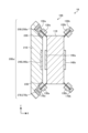
- FIG. 1 is a perspective view showing an example of a configuration of a linear transport device according to a first embodiment
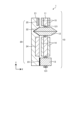
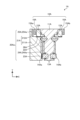
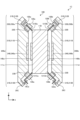
- FIG. 1 is a cross-sectional view showing an example of a configuration of a linear transport device according to a first embodiment.
- FIG. 1 is a diagram for explaining the effect of the linear transport device according to the first embodiment.
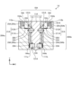
- FIG. 4 is an overhead view showing an example of a branching portion and its vicinity of the linear transport device according to the first embodiment;
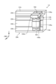
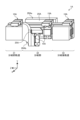
- FIG. 13 is a perspective view showing an example of a configuration of a linear transport device according to a second embodiment.
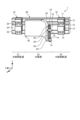
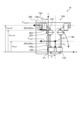
- FIG. 11 is a cross-sectional view showing an example of the configuration of a linear transport device according to a second embodiment, taken at a position other than a branch portion.
- FIG. 11 is a cross-sectional view showing an example of the configuration of a linear transport device according to a second embodiment, taken at a branching portion.
- FIG. 13 is a diagram for explaining the effect of the linear transport device according to the second embodiment.
- FIG. 13 is an overhead view showing another example of the vicinity of the branching portion of the linear transport device according to the second embodiment;
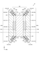
- FIG. 11 is a cross-sectional view showing an example of the configuration of a linear transport device according to a third embodiment, taken at a position other than a branch portion.
- FIG. 11 is a cross-sectional view showing an example of the configuration of a linear transport device according to a third embodiment, taken at a branching portion.
- FIG. 13 is a diagram for explaining the effect of the linear transport device according to the third embodiment.
- FIG. 11 is a cross-sectional view showing another example of the configuration of the linear transport device according to the third embodiment.
- FIG. 13 is a cross-sectional view showing another example of the configuration of the linear transport
- FIG. 1 is a perspective view showing an example of the configuration of a linear transport device according to the first embodiment
- FIG. 2 is a cross-sectional view showing an example of the configuration of a linear transport device according to the first embodiment.
- the traveling direction of the transport vehicle 10 is the Z direction
- the up-down direction is the Y direction
- the direction perpendicular to the two directions of the Z direction and the Y direction is the X direction.
- the X direction is also referred to as the width direction.
- the Y direction is the vertical direction.
- the two relative positional relationships in the Y direction may be expressed using "up" or "down".
- the linear transport device 1 is a device that moves the transport vehicle 10, which transports an object to be transported (not shown), by a linear motor along a stator side frame 20 arranged in the width direction of the transport vehicle 10, and has a portion where the stator side frame 20 is arranged on one side in the width direction.
- the linear transport device 1 includes the transport vehicle 10 and the stator side frame 20.
- the transport cart 10 has a transport cart main structure 11, an upper V-shaped roller 12, a lower flat roller 13, a driving mover side magnetic element 14, and a moving member side magnetic element 15 for generating an opposing moment.
- the transport cart main structure 11 is a member that supports the object to be transported. Specifically, the transport cart main structure 11 is a member on which the object to be transported can be placed or fixed along the stator side frame 20. In the example of Figures 1 and 2, the transport cart main structure 11 is composed of a plate-shaped member.
- the side surfaces of the transport cart main structure 11, which are planes parallel to the Z direction and the Y direction, are larger than the front and rear surfaces, which are planes perpendicular to the Z direction, and the top and bottom surfaces, which are planes perpendicular to the Y direction.
- the upper V-shaped rollers 12 are provided on the upper part of the main structure 11 of the transport cart. In the X direction, the size of the upper V-shaped rollers 12 is larger than the size of the main structure 11 of the transport cart. In Figs. 1 and 2, the stator side frame 20 is only arranged on one side of the transport cart 10 in the X direction, but the stator side frame 20 may be arranged on the other side of the transport cart 10 in the X direction, or on both sides. Each of the upper V-shaped rollers 12 can abut against the upper V-groove rail 22 of the stator side frame 20 regardless of which side of the transport cart 10 in the X direction the stator side frame 20 is on. In the example of Fig.
- the upper V-shaped rollers 12 are supported by a rotating shaft 121 provided on the upper part of the main structure 11 of the transport cart, and rotate around the rotating shaft 121.
- the rotating shaft 121 extends in the Y direction.
- the upper V-shaped roller 12 rotates in a horizontal plane.
- the shape of the rolling surface present on the radial periphery is a V shape that fits into the rail of the stator side frame 20 described below.
- the lower flat rollers 13 are provided at the bottom of the main structure 11 of the transport cart. In the X direction, the size of the lower flat rollers 13 is larger than that of the main structure 11 of the transport cart. As a result, similar to the case of the upper V-shaped rollers 12, each of the lower flat rollers 13 can abut against the lower flat rail 23 of the stator side frame 20 regardless of which side of the transport cart 10 in the X direction the stator side frame 20 is on. In the example of FIG. 1, two lower flat rollers 13 are provided at intervals in the Z direction, but the number of lower flat rollers 13 can be arbitrary.
- the lower flat rollers 13 are supported by a rotating shaft 131 provided at the bottom of the main structure 11 of the transport cart and rotate around the rotating shaft 131.
- the rotating shaft 131 extends in the Y direction. That is, the lower flat rollers 13 rotate in a horizontal plane. In a cross section passing through the rotating shaft 131 of the lower flat rollers 13, the shape of the rolling surface present in the radial peripheral portion is flat.
- the upper V-shaped roller 12 corresponds to a first roller provided on the transport cart main structure 11, and the lower flat roller 13 corresponds to a second roller provided at a different height than the first roller on the transport cart main structure 11.
- the upper V-shaped roller 12 corresponds to a V-shaped roller
- the lower flat roller 13 corresponds to a flat roller. Note that in Figures 1 and 2, the upper V-shaped roller 12 is positioned above the lower flat roller 13, but the hierarchical relationship between the upper V-shaped roller 12 and the lower flat roller 13 may be reversed. In this case, the transport cart main structure 11 will be equipped with an upper flat roller and a lower V-shaped roller.
- the driving mover side magnetic element 14 is provided on both side surfaces in the X direction of the transport carriage main structure 11, and drives the transport carriage main structure 11 relative to the stator side frame 20.
- the driving mover side magnetic element 14 is provided on both side surfaces in the X direction of the transport carriage main structure 11 between the upper V-shaped roller 12 and the lower flat roller 13.
- the driving mover side magnetic element 14 is a permanent magnet or an electromagnet.
- the driving mover side magnetic element 14 corresponds to the mover side magnetic element.
- the opposing moment generating movable magnetic element 15 is disposed above both side surfaces of the transport cart main structure 11 in the X direction, and generates an opposing moment between the movable magnetic element 15 and the stator side frame 20 to counter the tipping of the transport cart 10. Specifically, when the transport cart 10 is in a "cantilevered state", the opposing moment generating movable magnetic element 15 generates in the transport cart 10 an opposing moment that counters the tipping moment caused by the load in the vertical direction of the transport cart 10. In the example of Figures 1 and 2, the opposing moment generating movable magnetic element 15 is provided above the upper V-roller 12. In one example, the opposing moment generating movable magnetic element 15 is a permanent magnet or an electromagnet. A permanent magnet and an electromagnet are examples of magnetic elements. The opposing moment generating movable magnetic element 15 corresponds to the movable counter moment generating element.
- the stator side frame 20 has a frame structure 21, an upper V-groove rail 22, a lower flat rail 23, a driving stator side magnetic element 24, and a counter moment generating stator side magnetic element 25.
- the platform structure 21 is a support member that supports the transport cart 10 while it is moving.
- the platform structure 21 is provided along the movement path of the transport cart 10.
- the upper V-groove rail 22 is provided on the upper part of the frame structure 21 and is a rail with a V-shaped running surface.
- the upper V-groove rail 22 is provided at a position corresponding to the upper V-shaped roller 12 of the transport cart 10 and engages with the upper V-shaped roller 12.
- the lower flat rail 23 is provided on the lower part of the mounting structure 21 and is a rail with a flat running surface.
- the lower flat rail 23 is provided at a position corresponding to the lower flat roller 13 of the transport cart 10 on the main surface of the mounting structure 21 on the side where the transport cart 10 is placed, and engages with the lower flat roller 13.
- the upper V-groove rail 22 corresponds to a first rail provided on the frame structure 21 and engages with the upper V-shaped roller 12, which is the first roller
- the lower flat rail 23 corresponds to a second rail provided on the frame structure 21 and engages with the lower flat roller 13, which is the second roller.
- the upper V-groove rail 22 corresponds to the V-groove rail
- the lower flat rail 23 corresponds to the flat rail.
- the V-groove rail and the flat rail are provided to match the positions of the V-shaped rollers and flat rollers of the transport cart 10. Therefore, if the vertical relationship between the upper V-shaped rollers 12 and the lower flat rollers 13 is reversed on the transport cart 10, the vertical relationship between the upper V-groove rail 22 and the lower flat rail 23 will also be reversed on the stator side frame 20.
- the driving stator side magnetic element 24 pairs with the driving mover side magnetic element 14 to generate a magnetic attraction force in the horizontal direction.
- the driving stator side magnetic element 24 is provided on the side of the frame structure 21 between the upper V-groove rail 22 and the lower flat rail 23 that faces the transport carriage 10.
- the driving stator side magnetic element 24 is a permanent magnet or an electromagnet.
- the driving stator side magnetic element 24 corresponds to the stator side magnetic element.
- the opposing moment generating stator side magnetic element 25 is disposed above the frame structure 21, and generates an opposing moment by the horizontal attractive force generated between the opposing moment generating mover side magnetic element 15 and the opposing moment generating mover side magnetic element 15.
- the opposing moment generating stator side magnetic element 25 is provided on the side of the frame structure 21 above the upper V-groove rail 22 on the side where the transport cart 10 is disposed.
- the opposing moment generating stator side magnetic element 25 is an electromagnet or a permanent magnet. Permanent magnets and electromagnets are examples of magnetic elements.
- the opposing moment generating stator side magnetic element 25 is disposed on the frame structure 21, and corresponds to a stator side opposing moment generating element that generates an opposing moment between the opposing moment generating mover side magnetic element 15, which is the opposing moment generating mover side opposing moment generating element and ...
- the stator side frame 20 may have a branching section. At the branching section, the stator side frame 20 is arranged on both sides of the transport cart 10 in the X direction, and at other than the branching section, the stator side frame 20 is arranged on one side of the transport cart 10 in the X direction.
- the upper V-shaped rollers 12 of the transport cart 10 engage with the upper V-groove rails 22 of the stator side frame 20, and the lower flat rollers 13 of the transport cart 10 engage with the lower flat rails 23 of the stator side frame 20, allowing the transport cart 10 to move along the stator side frame 20.
- the driving mover side magnetic element 14 and the driving stator side magnetic element 24 form a linear motor.
- at least one of the driving mover side magnetic element 14 and the driving stator side magnetic element 24 is an electromagnet.
- the vertical movement of the transport cart 10 is constrained by the upper V-shaped rollers 12 arranged on the transport cart 10 and the upper V-groove rails 22 on the stator side frame 20 that engage with the upper V-shaped rollers 12.
- the upper V-shaped rollers 12 and lower flat rollers 13 of the transport cart 10 contact the upper V-groove rails 22 and lower flat rails 23, respectively, and the aforementioned driving mover side magnetic element 14 and driving stator side magnetic element 24 generate a magnetic attraction force to the left side in FIG. 2, i.e., the negative side in the X direction, so as to press the transport cart 10 against the stator side frame 20, thereby constraining the lateral movement of the transport cart 10.
- the configuration and operation of the first embodiment shown here are the same as those in Patent Document 1.
- the transport cart 10 is provided with a moving element magnetic element 15 for generating opposing moment, which is an attraction force generating element, above the main structure 11 of the transport cart, and the stator side frame 20 is provided with a moving element magnetic element 25 for generating opposing moment, which is an attraction force generating element, above the frame structure 21.
- a horizontal magnetic attraction force is generated between the moving element magnetic element 15 for generating opposing moment and the stator side magnetic element 25 for generating opposing moment.
- the stator side frame 20 when the stator side frame 20 is arranged on one side of the transport cart 10 in the X direction, for example, when the transport cart 10 is located at a position other than the branching section, the moving element magnetic element 15 for generating opposing moment generates an attraction force between the moving element magnetic element 25 for generating opposing moment.
- the upper part of the transport cart 10 is attracted to the stator side frame 20, and when the transport cart 10 is in a "cantilevered state", it is possible to suppress the transport cart 10 from falling due to a falling moment caused by a load in the vertical direction.
- At least one of the opposing moment generating movable magnetic element 15 and the opposing moment generating stator magnetic element 25 may be an electromagnet, and the control device may control the energization of the electromagnet in synchronization with the energization control of the linear motor.
- Figures 1 and 2 show an example in which the attraction force generating element is a magnetic element
- the attraction force generating element may be based on a method other than a magnetic element.
- One example is a case in which an attraction force generating element is provided above the transport cart 10, which sucks in air between the top of the transport cart 10 and the top of the stator side frame 20. Compared to such methods that use air pressure, the method that uses a magnetic element does not require electricity to generate attraction force.
- FIG. 3 is a diagram for explaining the effect of the linear transport device according to the first embodiment.
- point P corresponds to the center of rotation, which is the center when the transport cart 10 falls when the transport cart 10 is in contact with the stator side frame 20.
- a falling moment Mt acts, which is a moment consisting of the product of the gravity Fg of the transport cart 10 in the Y direction, which is the up-down direction, and the horizontal distance xg from point P to the overall center of gravity position G of the transport cart 10.
- the horizontal distance xg is the distance in the X direction.
- a horizontal magnetic attraction force Fmag.add is generated between the opposing moment generating mover side magnetic element 15 and the opposing moment generating stator side magnetic element 25 arranged above the transport cart 10 and the stator side base 20, respectively. This makes it possible to increase the opposing moment against the toppling moment Mt.
- the condition for preventing the above-mentioned transporting vehicle 10 from tipping over will be formulated. If the gravity acting on the transporting vehicle 10 is Fg , the horizontal distance from point P to the position of the overall center of gravity G of the transporting vehicle 10 is xg , the horizontal magnetic attraction force by the driving mover side magnetic element 14 and the driving stator side magnetic element 24 is Fmag.d , the distance in the Y direction, which is the vertical direction from point P to the center of the magnetic attraction force Fmag.d of the transporting vehicle 10 is ymag.d , the horizontal magnetic attraction force between the counter moment generating mover side magnetic element 15 and the counter moment generating stator side magnetic element 25 is Fmag.add , and the distance in the Y direction from point P to the center of the magnetic attraction force Fmag.add by the counter moment generating elements is ymag.add , the condition for preventing the transporting vehicle 10 from tipping over is that the following formula (1) is established.
- the attractive force between the opposing moment generating movable magnetic element 15 and the opposing moment generating stator magnetic element 25, and the distance in the Y direction between the center of the attractive force and point P are determined based on the magnetic attractive force between the driving movable magnetic element 14 and the driving stator magnetic element 24, and the distance in the Y direction between the center of this magnetic attractive force and point P.
- FIG. 4 is an overhead view showing an example of the vicinity of the branching section of the linear transport device according to the first embodiment.
- the stator side mounts 20 are present on both sides of the transport cart 10 in the X direction.
- the transport cart 10 is controlled by a control device (not shown) so that it does not adhere to both stator side mounts 20 at the same time, but adheres to one of the stator side mounts 20.
- the transport cart 10 is provided with a counter moment generating mover side magnetic element 15 on the upper side
- the stator side frame 20 on all tracks is provided with a counter moment generating stator side magnetic element 25 on the upper side.
- a magnetic attraction force is always generated between the counter moment generating mover side magnetic element 15 of the transport cart 10 and the counter moment generating stator side magnetic element 25 of the stator side frame 20.
- the tipping moment generated by the load in the vertical direction of the transport cart 10 is offset by a counter moment including a moment generated by a magnetic attraction force generated between the drive mover side magnetic element 14 and the drive stator side magnetic element 24, and a moment generated by a magnetic attraction force generated between the counter moment generating mover side magnetic element 15 and the counter moment generating stator side magnetic element 25.
- a counter moment including a moment generated by a magnetic attraction force generated between the drive mover side magnetic element 14 and the drive stator side magnetic element 24, and a moment generated by a magnetic attraction force generated between the counter moment generating mover side magnetic element 15 and the counter moment generating stator side magnetic element 25.
- Embodiment 2 A vertical load is constantly applied to the transporting cart 10 due to gravity and the like. Depending on the weight of the transported object, in the technology described in Patent Document 1, the U-shaped or V-shaped rollers that bear the vertical load may fall off or become severely worn. Therefore, Prior Art 1 shown below discloses a linear motor in which a stator side frame is always arranged on both sides of the transporting cart on the entire track except for the branching section, and upper and lower rollers arranged on both sides in the width direction of the transporting cart are engaged with the rails of the stator side frame on both sides in the width direction.
- Prior Art 1 discloses a structure in which rollers that engage with rails added to the top surface of the stator side frame and support the transporting cart in the vertical direction are added to the upper part of both the left and right sides of the transporting cart, thereby improving the vertical support load capacity of the transporting cart.
- Prior Art 1 U.S. Patent Application Publication No. 2020/0028427
- the rollers on the opposite side for supporting the vertical load do not engage with the rails, creating a "cantilevered state" in which the vertical load is supported only by the rail of the stator side frame on the attracting side and the rollers that engage with it.
- FIG. 5 is a perspective view showing an example of the configuration of a linear transport device according to embodiment 2.
- FIG. 6 is a cross-sectional view showing an example of the configuration of a linear transport device according to embodiment 2 at a position other than the branching portion.
- FIG. 7 is a cross-sectional view showing an example of the configuration of a linear transport device according to embodiment 2 at the branching portion.
- FIG. 5 shows the state of the linear transport device 1A at the branching portion.
- FIGS. 6 and 7 show cross sections perpendicular to the Z direction. In the linear transport device 1A of embodiment 2, as illustrated in FIG.
- the transport cart 10A is supported by the stator side stands 20Aa and 20Ab on both sides in the X direction in a "double-supported state," and at the branching portion, as illustrated in FIG. 5 and FIG. 7, the transport cart 10A is supported by the stator side stand 20Aa on one side in the X direction in a "cantilevered state.”
- the linear transport device 1A includes the transport cart 10A and the stator side stands 20Aa and 20Ab.
- the transport cart 10A has a transport cart main structure 11A, an upper V-shaped roller 12A, a lower flat roller 13A, driving mover side magnetic elements 14Aa, 14Ab, opposing moment generating mover side magnetic elements 15Aa, 15Ab, and an additional roller 16A.
- the transport cart main structure 11A is a member that supports the object to be transported.
- the transport cart main structure 11A is T-shaped when viewed from the Z direction.
- the transport cart main structure 11A has a plate-shaped main body 111 whose YZ surface area is larger than the other surfaces, and two plate-shaped protrusions 112 that are provided on the upper end of the main body 111 and protrude on both sides in the X direction.
- the upper V-shaped rollers 12A are provided on both sides of the transport cart main structure 11A in the X direction and rotate around the rotation axis 121A, which is an axis extending in the Y direction.
- the upper V-shaped rollers 12A are provided on the upper part of the transport cart main structure 11A.
- the upper V-shaped rollers 12A are provided on the side perpendicular to the X direction of the main body part 111 below the protruding part 112 of the transport cart main structure 11A.
- Two upper V-shaped rollers 12A are provided with a space in the X direction, and two are provided with a space in the Z direction. That is, four upper V-shaped rollers 12A are provided.
- the number of upper V-shaped rollers 12A is not limited.
- the upper V-shaped rollers 12A are supported by the rotation axis 121A provided on the upper part of the main body part 111 of the transport cart main structure 11A.
- the upper V-shaped rollers 12A rotate in a horizontal plane.
- the shape of the rolling surface on the radial periphery is a V shape that fits into the rail of the stator side frame 20A, which will be described later.
- the lower flat rollers 13A are provided on both sides of the transport cart main structure 11A in the X direction and rotate around the rotation axis 131A, which is an axis extending in the Y direction.
- the lower flat rollers 13A are provided at the bottom of the main body 111 of the transport cart main structure 11A.
- Two lower flat rollers 13A are provided at intervals in the X direction, and two lower flat rollers 13A are provided at intervals in the Z direction. That is, four lower flat rollers 13A are provided.
- the number of lower flat rollers 13A is not limited.
- the lower flat rollers 13A are supported by the rotation axis 131A provided at the bottom of the main body 111 of the transport cart main structure 11A.
- the lower flat rollers 13A rotate in a horizontal plane. In a cross section passing through the rotation axis 131A of the lower flat rollers 13A, the shape of the rolling surface present on the radial periphery is flat.
- the upper V-shaped roller 12A corresponds to the first roller provided on the transport cart main structure 11A
- the lower flat roller 13A corresponds to the second roller provided at a different height than the first roller on the transport cart main structure 11A
- the upper V-shaped roller 12A corresponds to the V-shaped roller
- the lower flat roller 13A corresponds to the flat roller. Note that in Figures 5 to 7, the upper V-shaped roller 12A is positioned above the lower flat roller 13A, but the vertical relationship between the upper V-shaped roller 12A and the lower flat roller 13A may be reversed. In this case, the transport cart main structure 11A will be equipped with an upper flat roller and a lower V-shaped roller.
- the driving mover side magnetic element 14Aa is provided on the X-direction side 111a of the transport cart main structure 11A, and drives the transport cart main structure 11A relative to the stator side frame 20Aa.
- the driving mover side magnetic element 14Aa is provided on the X-direction side 111a of the main body part 111 of the transport cart main structure 11A between the upper V-shaped roller 12A and the lower flat roller 13A.
- the driving mover side magnetic element 14Ab is provided on the X-direction side 111b of the transport cart main structure 11A, and drives the transport cart main structure 11A relative to the stator side frame 20Ab.
- the driving mover side magnetic element 14Ab is provided on the side 111b perpendicular to the X-direction of the main body part 111 of the transport cart main structure 11A between the upper V-shaped roller 12A and the lower flat roller 13A.
- the drive mover side magnetic elements 14Aa, 14Ab are permanent magnets or electromagnets.
- the drive mover side magnetic elements 14Aa, 14Ab correspond to the mover side magnetic elements.
- the drive mover side magnetic element 14Aa and the drive mover side magnetic element 14Ab will be referred to as the drive mover side magnetic element 14A when they are not individually distinguished.
- the opposing moment generating mover side magnetic element 15Aa is arranged on the X-direction side surface 112a above the transport cart main structure 11A, and generates an opposing moment between the mover side magnetic element 15Aa and the stator side frame 20Aa to counter the tipping of the transport cart 10A.
- the opposing moment generating mover side magnetic element 15Aa is provided on the side surface 112a perpendicular to the X-direction of the protruding portion 112 of the transport cart main structure 11A.
- the opposing moment generating mover side magnetic element 15Ab is arranged on the X-direction side surface 112b above the transport cart main structure 11A, and generates an opposing moment between the mover side magnetic element 15Ab and the stator side frame 20Ab to counter the tipping of the transport cart 10A.
- the opposing moment generating mover side magnetic element 15Ab is provided on the side surface 112b perpendicular to the X-direction of the protruding portion 112 of the transport cart main structure 11A.
- the opposing moment generating movable magnetic elements 15Aa and 15Ab are electromagnets or permanent magnets.
- the opposing moment generating movable magnetic elements 15Aa and 15Ab When the transport vehicle 10A is in a "cantilevered state", the opposing moment generating movable magnetic elements 15Aa and 15Ab generate an opposing moment in the transport vehicle 10A, which is a moment that counteracts the toppling moment caused by the load in the vertical direction of the transport vehicle 10A.
- the opposing moment generating movable magnetic elements 15Aa and 15Ab correspond to the movable-side opposing moment generating element.
- the opposing moment generating movable magnetic element 15Aa and the opposing moment generating movable magnetic element 15Ab are referred to as the opposing moment generating movable magnetic element 15A when they are not individually distinguished.
- the additional rollers 16A are provided on both sides of the transport cart main structure 11A in the X direction, and rotate around the rotation axis 161A, which is an axis extending in the X direction.
- the additional rollers 16A are provided on the underside of the protruding portion 112 of the transport cart main structure 11A.
- Two additional rollers 16A are provided on each of the protruding portions 112, spaced apart in the Z direction.
- the number of additional rollers 16A is not limited.
- the additional rollers 16A are supported by the rotation axis 161A provided on the protruding portion 112.
- the additional rollers 16A rotate within the YZ plane. In a cross section passing through the rotation axis 161A of the additional rollers 16A, the shape of the rolling surface present on the radial peripheral portion is flat.
- stator side mounts 20Aa, 20Ab are provided on both sides of the transport cart 10A in the X direction. That is, the stator side mounts 20Aa, 20Ab are in a "double-supported state" in the area other than the branching section. Therefore, there is a stator side mount 20Aa that faces the side surface 111a of the main body 111, and a stator side mount 20Ab that faces the side surface 111b of the main body 111.
- stator side mount 20A when the stator side mounts 20Aa and stator side mounts 20Ab are not individually distinguished, they will be referred to as the stator side mount 20A.
- the stator side frame 20A has a frame structure 21A, an upper V-groove rail 22A, a lower flat rail 23A, a driving stator side magnetic element 24A, a counter moment generating stator side magnetic element 25A, and an additional rail 26A.
- the mounting structure 21A is a support member that supports the transport cart 10A while moving it.
- the mounting structure 21A is provided along the movement path of the transport cart 10A.
- the mounting structure 21A has a main body 211A and a side wall 212A provided at the upper part of the main body 211A on the side opposite to the side on which the transport cart 10A is placed.
- the side wall 212A is provided on the upper surface of the main body 211A, protruding in the Y direction. The space above the main body 211A, surrounded by the upper surface of the main body 211A and the side wall 212A, allows the protrusion 112 of the transport cart main structure 11A to pass through.
- the upper V-groove rail 22A is provided on the upper part of the main body 211A of the frame structure 21A, and is a rail with a V-shaped running surface.
- the upper V-groove rail 22A is provided at a position corresponding to the upper V-shaped roller 12A of the transport cart 10A, and engages with the upper V-shaped roller 12A.
- the lower flat rail 23A is provided on the lower part of the main body 211A of the mounting structure 21A, and is a rail with a flat running surface.
- the lower flat rail 23A is provided on the side of the mounting structure 21A facing the transport cart 10A at a position corresponding to the lower flat roller 13A of the transport cart 10A, and engages with the lower flat roller 13A.
- the upper V-groove rail 22A is provided on the frame structure 21A and corresponds to a first rail that engages with the upper V-shaped roller 12A, which is the first roller
- the lower flat rail 23A is provided on the frame structure 21A and corresponds to a second rail that engages with the lower flat roller 13A, which is the second roller.
- the upper V-groove rail 22A corresponds to the V-groove rail
- the lower flat rail 23A corresponds to the flat rail. Note that the V-groove rail and the flat rail are provided to match the positions of the V-shaped roller and flat roller of the transport cart 10A.
- the driving stator side magnetic element 24A is paired with the driving mover side magnetic element 14A to generate a magnetic attraction force in the horizontal direction.
- the driving stator side magnetic element 24A is provided on the side facing the transport cart 10A in the main body 211A of the frame structure 21A between the upper V-groove rail 22A and the lower flat rail 23A.
- the driving stator side magnetic element 24A is a permanent magnet or an electromagnet.
- the driving stator side magnetic element 24A of the stator side frame 20Aa is referred to as the driving stator side magnetic element 24Aa
- the driving stator side magnetic element 24A of the stator side frame 20Ab is referred to as the driving stator side magnetic element 24Ab.
- the driving stator side magnetic element 24A corresponds to the stator side magnetic element.
- the counter moment generating stator side magnetic element 25A is arranged above the mounting structure 21A, and generates a counter moment by the horizontal attractive force generated between it and the paired counter moment generating mover side magnetic element 15A.
- the counter moment generating stator side magnetic element 25A is provided on the side surface facing the transport cart 10A in the side wall portion 212A of the mounting structure 21A.
- the counter moment generating stator side magnetic element 25A is an electromagnet or a permanent magnet.
- the counter moment generating stator side magnetic element 25A is arranged on the mounting structure 21A, and corresponds to a stator side counter moment generating element that generates a counter moment between it and the paired mover side counter moment generating element, the counter moment generating mover side magnetic element 15A.
- the opposing moment generating stator side magnetic element 25A of the stator side frame 20Aa is referred to as the opposing moment generating stator side magnetic element 25Aa
- the opposing moment generating stator side magnetic element 25A of the stator side frame 20Ab is referred to as the opposing moment generating stator side magnetic element 25Ab.
- the additional rail 26A is provided on the upper surface of the main body 211A of the mounting structure 21A and is a rail with a flat running surface.
- the additional rail 26A engages with the additional roller 16A.
- stator side mounts 20Aa, 20Ab on both sides of the transport cart 10A in the X direction branch off, and the stator side mount 20A is arranged only on one side of the transport cart 10A in the X direction.
- stator side mounts 20Aa, 20Ab are arranged on both sides of the transport cart 10A in the X direction.
- the transport cart 10A has the driving mover side magnetic elements 14Aa, 14Ab, the upper V-shaped roller 12A, and the lower flat roller 13A on both sides in the X direction.
- the stator side frames 20Aa, 20Ab are present on both sides in the X direction of the transport cart 10A, and the driving mover side magnetic elements 14Aa, 14Ab and the driving stator side magnetic elements 24Aa, 24Ab form a linear motor.
- at least one of the driving mover side magnetic elements 14Aa, 14Ab and the driving stator side magnetic elements 24Aa, 24Ab is an electromagnet.
- an additional roller 16A having a rotating shaft 161A extending in the X direction is added to the transport cart 10A, and an additional rail 26A is added to the upper surface of the main body 211A of the stator side frame 20A.
- the upper V-shaped roller 12A of the transport cart 10A engages with the upper V-groove rail 22A of the stator side frame 20A
- the lower flat roller 13A of the transport cart 10A engages with the lower flat rail 23A of the stator side frame 20A
- the additional roller 16A of the transport cart 10A engages with the additional rail 26A of the stator side frame 20A. This allows the transport cart 10A to move along the stator side frame 20A.
- the upper V-shaped rollers 12A, lower flat rollers 13A, and additional rollers 16A on both sides of the transport cart 10A in the X direction are engaged with the upper V-groove rails 22A, lower flat rails 23A, and additional rails 26A of the stator side frames 20Aa, 20Ab on both the left and right sides in a "double-supported state," so tipping of the transport cart 10A is not a problem.
- the stator side frame 20A at the branching point or the like is positioned on one side of the transport cart 10A in the X direction, the stator side frames 20Aa, 20Ab on both sides of the transport cart 10A in the X direction branch off.
- the transport carriage 10A is driven while being attracted only to the stator side frame 20A on one side due to the magnetic attraction between the driving stator side magnetic element 24Aa of the stator side frame 20A on one side of the stator side frames 20A on both sides in the X direction and the driving mover side magnetic element 14Aa of the transport carriage 10A.
- the transport cart 10A is in a "cantilevered state" supported by the engagement between the upper V-shaped roller 12A on the suction side and the upper V-groove rail 22A, the engagement between the lower flat roller 13A and the lower flat rail 23A, and the engagement between the additional roller 16A and the additional rail 26A.
- this "cantilevered state” it is necessary to take into consideration the tipping of the transport cart 10A, as in embodiment 1.
- the transport cart 10A is provided with opposing moment generating mover side magnetic elements 15Aa, 15Ab, which are attraction force generating elements, above the transport cart main structure 11A
- the stator side frame 20A is provided with opposing moment generating stator side magnetic elements 25Aa, 25Ab, which are attraction force generating elements, on the side wall portion 212A above the frame structure 21A.
- a horizontal magnetic attraction force is generated between these opposing moment generating mover side magnetic elements 15Aa and opposing moment generating stator side magnetic elements 25Aa, or between the opposing moment generating mover side magnetic elements 15Ab and opposing moment generating stator side magnetic elements 25Ab.
- At least one of the opposing moment generating movable magnetic elements 15Aa, 15Ab and the opposing moment generating stator magnetic elements 25Aa, 25Ab may be an electromagnet, and the control device may control the energization of the electromagnet in synchronization with the energization control of the linear motor.
- FIG. 8 is a diagram for explaining the effect of the linear conveying device according to the second embodiment.
- a tilting moment Mt acts, which is a moment consisting of the product of the gravity F g of the conveying carriage 10A in the Y direction, which is the vertical direction, and the horizontal distance x g from point P1 to the overall center of gravity position G1 of the conveying carriage 10A.
- the horizontal direction corresponds to the X direction.
- This tilting moment Mt acts to tilt the conveying carriage 10A around point P1.
- the moment consisting of the product of the horizontal magnetic attraction force F mag.d by the driving movable member side magnetic element 14Aa and the driving stator side magnetic element 24Aa and the distance y mag.d in the Y direction, which is the vertical direction, from point P1 to the center of the magnetic attraction force F mag.d of the conveying carriage 10A, becomes an opposing moment.
- the moment obtained by multiplying the lateral friction force F fric.add between the additional roller 16A and the additional rail 26A by the distance y fric.add in the Y direction, which is the vertical direction from point P1 to the additional rail 26A, is also the counter moment.
- the configuration and effect so far are the same as those of the prior art 1, and as in the first embodiment, if the tipping moment Mt exceeds the counter moment, the transporting cart 10A will tip over. For this reason, even in the technology described in the prior art 1, it was necessary to set a limit on the weight of the transported object or the horizontal distance x g between the center of gravity of the transporting cart 10A and point P1.
- a horizontal magnetic attraction force Fmag.add is generated between the opposing moment generating mover side magnetic element 15Aa and the opposing moment generating stator side magnetic element 25Aa, which are disposed above the transport vehicle 10A and the stator side base 20A , respectively. This makes it possible to increase the opposing moment against the toppling moment Mt.
- the magnetic attractive force F fric.add in the counter moment generating element can be increased or the distance y fric.add from point P1 to the center of the magnetic attractive force F fric.add of the counter moment generating element can be made wider.
- the attractive force between the opposing moment generating movable magnetic element 15A and the opposing moment generating stator magnetic element 25A, and the distance in the Y direction between the center of the attractive force and point P1 are determined based on the magnetic attractive force between the driving movable magnetic element 14A and the driving stator magnetic element 24A, and the distance in the Y direction between the center of this magnetic attractive force and point P1.
- the lateral friction force F fric.add between the additional roller 16A and the additional rail 26A acts as a counter moment
- the lateral friction force F fric.add is generally very small compared to the other components, and its effect as a counter moment is minimal.
- the stator side frames 20A are arranged on both sides of the transport cart 10A in the X direction, and the transport cart 10A is in a "double-supported state.”
- the transport cart 10A is locally in a "cantilevered state.” Because there is a possibility that the transport cart 10A may tip over at this branching section, Prior Art 1 places restrictions on the overall weight or center of gravity position of the transport cart 10A.
- a horizontal magnetic attraction force is generated by an element that generates an opposing moment, preventing the transport cart 10A from tipping over and mitigating the restrictions on the overall weight or center of gravity position of the transport cart 10A.
- FIG. 9 is an overhead view showing another example of the vicinity of the branching section of the linear transport device according to embodiment 2.
- the stator side base 20A is arranged such that the counter moment generating stator side magnetic element 25A is placed only at the branching section 32 where the transport carriage 10A is in a "cantilevered state,” and is omitted, i.e., not placed, on the other tracks, i.e., on the pre-branching track 31 and the post-branching track 33.
- the second embodiment can achieve the same effect as the first embodiment.
- Embodiment 3 discloses a transportation system in which a stator frame is placed on both sides of the transport cart at all times on the entire track except for the branching sections, rollers whose rolling surfaces have equal inclination angles to the vertical direction are provided on the top and bottom of both the left and right sides of the transport cart, and these rollers are engaged with the rails of the stator frame, thereby supporting the transport cart in the vertical direction.
- Prior Art 2 International Publication No. 2015/042409
- FIG. 10 is a cross-sectional view at a position other than the branching portion, showing an example of the configuration of a linear transport device according to embodiment 3.
- FIG. 11 is a cross-sectional view at the position of the branching portion, showing an example of the configuration of a linear transport device according to embodiment 3.
- FIGS. 10 and 11 show cross sections perpendicular to the Z direction.
- linear transport device 1B of embodiment 3 is in a "double-supported state" as shown in FIG. 10 at a position other than the branching portion, and in a "cantilevered state” at the branching portion as shown in FIG. 11.
- Linear transport device 1B comprises transport carriage 10B and stator side stands 20Ba and 20Bb.
- the transport cart 10B has a transport cart main structure 11B, upper flat rollers 12Ba, 12Bb, lower flat rollers 13Ba, 13Bb, driving mover side magnetic elements 14Ba, 14Bb, opposing moment generating mover side upper magnetic elements 15Ba, 15Bb, and opposing moment generating mover side lower magnetic elements 17Ba, 17Bb.
- the transport cart main structure 11B is a member that supports the object to be transported.
- the transport cart main structure 11B is composed of a plate-like member in which the side surfaces 111c, 111d, which are parallel to the Z direction and the Y direction, are larger than the front and rear surfaces, which are perpendicular to the Z direction, and the top and bottom surfaces, which are perpendicular to the Y direction.
- the upper flat roller 12Ba is provided above the transport cart main structure 11B in the X direction, specifically, at the upper part of the transport cart main structure 11B on the stator side frame 20Ba side.
- the upper flat roller 12Ba is supported by a rotating shaft 121Ba inclined at a predetermined inclination angle from the Y direction, and rotates around the rotating shaft 121Ba.
- the upper flat roller 12Bb is provided above the transport cart main structure 11B in the X direction, specifically, at the upper part of the transport cart main structure 11B on the stator side frame 20Bb side.
- the upper flat roller 12Bb is supported by a rotating shaft 121Bb inclined at a predetermined inclination angle from the Y direction, and rotates around the rotating shaft 121Bb.
- the rotating shafts 121Ba, 121Bb extend from the Y direction toward the X direction in a direction of a predetermined inclination angle greater than 0 degrees and less than or equal to 90 degrees.
- the rotating shafts 121Ba and 121Bb are arranged so that they are at angles set in opposite directions from the vertical direction in the XY plane. In other words, the rolling surfaces of the upper flat rollers 12Ba and 12Bb are inclined with respect to the Y direction.
- the shape of the rolling surfaces present on the radial periphery is flat.
- the upper flat rollers 12Ba and 12Bb correspond to the first rollers provided on the transport cart main structure 11B.
- the rotating shafts 121Ba and 121Bb correspond to the upper rotating shafts.
- the lower flat roller 13Ba is provided below the X-direction of the transport cart main structure 11B, specifically, at the lower part of the stator side frame 20Ba side of the transport cart main structure 11B.
- the lower flat roller 13Ba is supported by a rotating shaft 131Ba that is inclined at a predetermined inclination angle from the Y-direction, and rotates around the rotating shaft 131Ba.
- the lower flat roller 13Bb is provided below the X-direction of the transport cart main structure 11B, specifically, at the lower part of the stator side frame 20Bb side of the transport cart main structure 11B.
- the lower flat roller 13Bb is supported by a rotating shaft 131Bb that is inclined at a predetermined inclination angle from the Y-direction, and rotates around the rotating shaft 131Bb.
- the rotating shafts 131Ba, 131Bb extend from the Y-direction toward the X-direction at a predetermined inclination angle greater than 0 degrees and less than or equal to 90 degrees.
- the rotating shafts 131Ba and 131Bb are arranged so that they are at angles set in opposite directions from the negative side of the Y direction in the XY plane. In other words, the rolling surfaces of the lower flat rollers 13Ba and 13Bb are inclined with respect to the Y direction.
- the shape of the rolling surfaces present on the radial periphery is flat.
- the lower flat rollers 13Ba and 13Bb correspond to second rollers that are arranged at a different height from the first rollers of the transport cart main structure 11B.
- the rotating shafts 131Ba and 131Bb correspond to the lower rotating shafts.
- the driving mover side magnetic element 14Ba is provided on the X-direction side 111c of the transport cart main structure 11B, and drives the transport cart main structure 11B relative to the stator side frame 20Ba.
- the driving mover side magnetic element 14Ba is provided on the X-direction side 111c of the transport cart main structure 11B between the upper flat roller 12Ba and the lower flat roller 13Ba.
- the driving mover side magnetic element 14Bb is provided on the X-direction side 111d of the transport cart main structure 11B, and drives the transport cart main structure 11B relative to the stator side frame 20Bb.
- the driving mover side magnetic element 14Ba is provided on the X-direction side 111d of the transport cart main structure 11B between the upper flat roller 12Bb and the lower flat roller 13Bb.
- the drive mover side magnetic elements 14Ba, 14Bb are permanent magnets or electromagnets.
- the drive mover side magnetic elements 14Ba, 14Bb correspond to the mover side magnetic elements.
- the drive mover side magnetic elements 14Ba, 14Bb are not individually distinguished, they are referred to as the drive mover side magnetic element 14B.
- the upper magnetic element 15Ba on the movable member side for generating a counter moment is disposed at the tip of the rotating shaft 121Ba of the upper flat roller 12Ba, and generates an attractive force between the movable member side and the stator side frame 20Ba.
- the upper magnetic element 15Bb on the movable member side for generating a counter moment is disposed at the tip of the rotating shaft 121Bb of the upper flat roller 12Bb, and generates an attractive force between the movable member side and the stator side frame 20Ba.
- the upper magnetic elements 15Ba, 15Bb on the movable member side for generating a counter moment are electromagnets or permanent magnets.
- the upper magnetic elements 15Ba, 15Bb on the movable member side for generating a counter moment generate a counter moment in the transport cart 10B that counters the tipping moment caused by the load in the vertical direction of the transport cart 10B when the transport cart 10B is in a "cantilevered state".
- the upper magnetic elements 15Ba and 15Bb on the movable member side for generating the opposing moment correspond to the attractive force generating elements on the movable member side.
- the lower magnetic element 17Ba on the movable member side for generating a counter moment is disposed at the tip of the rotating shaft 131Ba of the lower flat roller 13Ba, and generates a repulsive force between the movable member side and the stator side frame 20Ba.
- the lower magnetic element 17Bb on the movable member side for generating a counter moment is disposed at the tip of the rotating shaft 131Bb of the lower flat roller 13Bb, and generates a repulsive force between the movable member side and the stator side frame 20Bb.
- the lower magnetic elements 17Ba, 17Bb on the movable member side for generating a counter moment are electromagnets or permanent magnets.
- the lower magnetic elements 17Ba, 17Bb on the movable member side for generating a counter moment generate a counter moment in the transporting cart 10B that counters the tipping moment caused by the load in the vertical direction of the transporting cart 10B when the transporting cart 10B is in a "cantilevered state".
- the lower magnetic elements 17Ba and 17Bb on the movable member side for generating opposing moment correspond to the repulsive force generating elements on the movable member side.
- the upper magnetic elements 15Ba, 15Bb on the movable member side for generating a counter moment and the lower magnetic elements 17Ba, 17Bb on the movable member side for generating a counter moment constitute the movable member side counter moment generating element.
- the movable member side counter moment generating element is disposed on both side surfaces of the transport carriage main structure 11B in the X direction, and generates a counter moment between the movable member side frame 20B and the stator side frame 20B to counter the tipping of the transport carriage 10B.
- stator side mounts 20Ba, 20Bb are provided on both sides of the transport cart 10B in the X direction in the areas other than the branching section.
- the stator side mounts 20Ba, 20Bb are in a "double-supported state" in the areas other than the branching section. Therefore, there is a stator side mount 20Ba that faces the side surface 111c of the transport cart main structure 11B, and a stator side mount 20Bb that faces the side surface 111d of the transport cart main structure 11B.
- the stator side mounts 20Ba and 20Bb will be referred to as the stator side mount 20B when they are not individually distinguished.
- the stator side frame 20B has a frame structure 21B, an upper flat rail 22B, a lower flat rail 23B, a driving stator side magnetic element 24B, an opposing moment generating stator side upper magnetic element 25B, and an opposing moment generating stator side lower magnetic element 27B.
- the mounting structure 21B is a support member that supports the transport cart 10B while moving it.
- the mounting structure 21B is provided along the movement path of the transport cart 10B.
- the mounting structure 21B has a main body 211B having a trapezoidal cross section perpendicular to the Z direction, an upper side wall 212B provided at the upper part of the main body 211B opposite the side where the transport cart 10B is arranged, and a lower side wall 213B provided at the lower part of the main body 211B opposite the side where the transport cart 10B is arranged.
- the space at the top of the main body 211B surrounded by the upper surface intersecting the Y direction of the main body 211B and the upper side wall 212B allows the upper flat rollers 12Ba, 12Bb and the upper magnetic elements 15Ba, 15Bb on the opposing moment generating movable member side to pass through.
- the upper flat rail 22B is provided on the upper surface of the main body 211B of the frame structure 21B that intersects with the Y direction, and is a rail with a flat running surface.
- the upper flat rail 22B is provided at a position corresponding to the upper flat rollers 12Ba, 12Bb of the transport cart 10B, and engages with the upper flat rollers 12Ba, 12Bb.
- the upper flat rail 22B is provided on the frame structure 21B, and corresponds to the first rail that engages with the upper flat rollers 12Ba, 12Bb, which are the first rollers.
- the lower flat rail 23B is a rail with a flat running surface, provided on the underside of the main body 211B of the frame structure 21B that intersects with the Y direction.
- the lower flat rail 23B is provided at a position corresponding to the lower flat rollers 13Ba, 13Bb of the transport cart 10B, and engages with the lower flat rollers 13Ba, 13Bb.
- the lower flat rail 23B corresponds to the second rail provided on the frame structure 21B, which engages with the second rollers, the lower flat rollers 13Ba, 13Bb.
- the driving stator side magnetic element 24B is paired with the driving mover side magnetic element 14B to generate a magnetic attraction force in the horizontal direction.
- the driving stator side magnetic element 24B is provided on the side facing the transport cart 10B in the main body 211B of the frame structure 21B between the upper flat rail 22B and the lower flat rail 23B.
- the driving stator side magnetic element 24B is a permanent magnet or an electromagnet.
- the driving stator side magnetic element 24B of the stator side frame 20Ba is referred to as the driving stator side magnetic element 24Ba
- the driving stator side magnetic element 24B of the stator side frame 20Bb is referred to as the driving stator side magnetic element 24Bb
- the driving stator side magnetic element 24B corresponds to the stator side magnetic element.
- the counter moment generating stator side upper magnetic element 25B pairs with the counter moment generating mover side upper magnetic elements 15Ba, 15Bb to generate an attractive force in the direction of the rotation shafts 121Ba, 121Bb.
- the counter moment generating stator side upper magnetic element 25B is provided on the side facing the transport cart 10B in the upper side wall portion 212B of the frame structure 21B.
- the counter moment generating stator side upper magnetic element 25B is an electromagnet or permanent magnet.
- the counter moment generating stator side upper magnetic element 25B corresponds to the stator side attractive force generating element.
- the counter moment generating stator side upper magnetic element 25B of the stator side frame 20Ba is referred to as the counter moment generating stator side upper magnetic element 25Ba
- the counter moment generating stator side upper magnetic element 25B of the stator side frame 20Bb is referred to as the counter moment generating stator side upper magnetic element 25Bb.
- the counter moment generating stator side lower magnetic element 27B pairs with the counter moment generating mover side lower magnetic elements 17Ba, 17Bb to generate a repulsive force in the direction of the rotation axes 131Ba, 131Bb.
- the counter moment generating stator side lower magnetic element 27B is provided on the side facing the transport cart 10B in the lower side wall portion 213B of the frame structure 21B.
- the counter moment generating stator side lower magnetic element 27B is an electromagnet or permanent magnet.
- the counter moment generating stator side lower magnetic element 27B corresponds to the stator side repulsive force generating element.
- the counter moment generating stator side lower magnetic element 27B of the stator side frame 20Ba is referred to as the counter moment generating stator side lower magnetic element 27Ba
- the counter moment generating stator side lower magnetic element 27B of the stator side frame 20Bb is referred to as the counter moment generating stator side lower magnetic element 27Bb.
- the counter moment generating stator side upper magnetic elements 25Ba, 25Bb and the counter moment generating stator side lower magnetic elements 27Ba, 27Bb constitute the stator side counter moment generating element.
- the stator side counter moment generating element is disposed on the mounting structure 21B, and generates a counter moment between itself and the paired mover side counter moment generating element.
- the vertical load of the transport cart 10A was supported by the upper V-shaped rollers 12A and additional rollers 16A provided on the transport cart 10A and the corresponding upper V-groove rails 22A and additional rails 26A on the stator side frame 20A.
- the vertical load of the transport cart 10B is supported by upper flat rollers 12Ba, 12Bb and lower flat rollers 13Ba, 13Bb, whose rolling surfaces have equal inclination angles with respect to the Y direction, which is the vertical direction.
- a horizontal magnetic attraction force is generated by the opposing moment generating mover side magnetic elements 15Aa, 15Ab provided at the top of the transport cart 10A and the opposing moment generating stator side upper magnetic elements 25Aa, 25Ab provided at the top of the stator side frame 20A.
- a magnetic attraction force in the direction of the rotation axes 121Ba, 121Bb is generated on the upper flat rollers 12Ba, 12Bb by the opposing moment generating mover side upper magnetic elements 15Ba, 15Bb of the transport cart 10B and the opposing moment generating stator side upper magnetic elements 25Ba, 25Bb of the stator side frame 20B.
- the lower magnetic elements 17Ba, 17Bb on the movable member side for generating a counter moment of the transport cart 10B and the lower magnetic elements 27Ba, 27Bb on the stator side for generating a counter moment of the stator side frame 20B generate a magnetic repulsive force in the direction of the rotation shafts 131Ba, 131Bb on the lower flat rollers 13Ba, 13Bb.
- the upper flat rollers 12Ba, 12Bb and the lower flat rollers 13Ba, 13Bb which have rolling surfaces arranged on both sides of the X direction of the transport cart 10B and have a fixed inclination angle with respect to the Y direction, which is the up-down direction, engage with the upper flat rails 22B and the lower flat rails 23B on the stator side frames 20Ba, 20Bb on both sides of the X direction in a "double-supported state," so that the tipping of the transport cart 10B is not a problem.
- stator side frames 20Ba, 20Bb on both sides of the X direction of the transport cart 10B branch off, and the stator side frame 20B is positioned on one side of the transport cart 10B in the X direction.
- the transport cart 10B moves along the stator side frame 20Ba, so that the stator side frame 20Ba is positioned on one side of the transport cart 10B in the X direction.
- the transport vehicle 10B is driven while being attracted only to the stator side frame 20Ba by the magnetic attraction between the driving stator side magnetic element 24Ba of the stator side frame 20Ba on one side and the driving mover side magnetic element 14Ba of the opposing transport vehicle 10B.
- the driving mover side magnetic element 14Ba and the driving stator side magnetic element 24Ba constitute a linear motor.
- at least one of the driving mover side magnetic element 14Ba and the driving stator side magnetic element 24Ba is an electromagnet.
- the upper flat roller 12Bb and the lower flat roller 13Bb on the opposite side to the side attracted to the stator side frame 20Ba of the transport vehicle 10B are not engaged with the upper flat rail 22B and the lower flat rail 23B.
- the transport cart 10B is in a "cantilevered state" supported by the engagement between the upper flat roller 12Ba on the side that is being attracted and the upper flat rail 22B, and the engagement between the lower flat roller 13Ba and the lower flat rail 23B.
- this "cantilevered state" occurs, as in the first and second embodiments, it is necessary to take into consideration the tipping of the transport cart 10B.
- the transport cart 10B includes upper magnetic elements 15Ba, 15Bb on the movable member side for generating a counter moment, and lower magnetic elements 17Ba, 17Bb on the movable member side for generating a counter moment.
- the stator side stands 20Ba, 20Bb include upper magnetic elements 25Ba, 25Bb on the movable member side for generating a counter moment, and lower magnetic elements 27Ba, 27Bb on the movable member side for generating a counter moment.
- an attractive force in this case a magnetic attractive force, is generated in the direction of the rotation axes 121Ba, 121Bb of the upper flat rollers 12Ba, 12Bb, respectively.
- a repulsive force in this case a magnetic repulsive force, is generated in the direction of the rotation shafts 131Ba and 131Bb of the lower flat rollers 13Ba and 13Bb.
- At least one of the opposing moment generating mover side upper magnetic elements 15Ba and 15Bb and the opposing moment generating stator side upper magnetic elements 25Ba and 25Bb may be an electromagnet, and the control device may control the supply of electricity to the electromagnet in synchronization with the control of the supply of electricity to the linear motor.
- At least one of the opposing moment generating mover side lower magnetic elements 17Ba, 17Bb and the opposing moment generating stator side lower magnetic elements 27Ba, 27Bb may be electromagnets, and the control device may control the energization of the electromagnets in synchronization with the energization control of the linear motor.
- the repulsive force generating element may be based on a method other than a magnetic element.
- One method uses air pressure as a repulsive force generating element.
- a repulsive force generating element is provided above the transport cart 10B, which pumps air to increase the air pressure between the lower flat rollers 13Ba, 13Bb and the lower side wall portion 213B.
- the method that uses a magnetic element does not require electricity to generate a repulsive force.
- FIG. 12 is a diagram for explaining the effect of the linear transport device according to embodiment 3.
- an example is taken of the case where the transport cart 10B is attracted to the stator side frame 20Ba.
- the balancing of the rotational moment considered in embodiment 3 concerns the balancing of rotation around the center O of the tangent circle C, which is a circle tangent to the engagement surface of the upper flat roller 12Ba and upper flat rail 22B and the engagement surface of the lower flat roller 13Ba and lower flat rail 23B in the XY plane.
- a toppling moment Mt acts around the center O of the tangent circle C, which is a moment formed by the product of the gravity Fg of the transporting vehicle 10B in the vertical Y direction and the horizontal distance xg from the center O of the tangent circle C to the overall center of gravity of the transporting vehicle 10B.
- This toppling moment Mt has the effect of toppling the transporting vehicle 10B around the center O of the tangent circle C.
- the horizontal direction corresponds to the X direction.
- the counter moment to this tilt moment Mt is the product of the horizontal magnetic attraction force F mag.d by the magnetic element 14Ba on the driving movable element side and the magnetic element 24Ba on the driving stator side, and the distance y mag.d in the Y direction, which is the vertical direction from the center O of the tangent circle C to the center of the magnetic attraction force F mag.d of the transporting carriage 10B.
- the transporting carriage 10B which is attracted in the lateral direction by the magnetic attraction force F mag.d , by the engagement between the upper flat roller 12Ba and the upper flat rail 22B, and the engagement between the lower flat roller 13Ba and the lower flat rail 23B, so that there is no difference in the respective support loads.
- the distance y mag.d in the Y direction from the center O of the tangent circle C to the center of the magnetic attraction force F mag.d of the transporting carriage 10B is zero or a very small value.
- the opposing moment resulting from the horizontal magnetic attraction force F mag.d by the driving mover side magnetic element 14Ba and the driving stator side magnetic element 24Ba in the third embodiment becomes zero or very small.
- the moment consisting of the product of the frictional force F fric.3A in the contact surface of the upper flat roller 12Ba and the upper flat rail 22B, the frictional force F fric.4A in the contact surface of the lower flat roller 13Ba and the lower flat rail 23B, and the radius R of the tangent circle C becomes the counter moment against the tipping moment.
- the frictional force on the engagement surface of the roller and the rail is very small compared to the tipping moment.
- the tipping moment of the transporting cart 10B of Prior Art 2 exceeds the opposing moment, and the transporting cart 10B easily falls over around the center O of the tangent circle C.
- the transporting cart 10B rotates and slides on the engagement surface between the upper flat roller 12Ba and the upper flat rail 22B and on the engagement surface between the lower flat roller 13Ba and the lower flat rail 23B, and falls off. For this reason, it was necessary to set a significant limit on the weight of the transported object or the distance xg between the center of gravity of the transporting cart 10B and the center O of the tangent circle C.
- a magnetic attraction force is generated in the direction of the rotation axis 121Ba of the upper flat roller 12Ba between the opposing moment generating mover side upper magnetic element 15Ba and the opposing moment generating stator side upper magnetic element 25Ba, which are arranged above the transport cart 10B and the stator side base 20Ba, respectively.
- a magnetic repulsion force is generated in the direction of the rotation axis 131Ba of the lower flat roller 13Ba between the opposing moment generating mover side lower magnetic element 17Ba and the opposing moment generating stator side lower magnetic element 27Ba, which are arranged below the transport cart 10B and the stator side base 20Ba, respectively. This makes it possible to increase the opposing moment against the tipping moment.
- the conditions for preventing the above-mentioned transport cart 10B from tipping over will now be formulated.
- the radius of the tangent circle C of the engagement surface of the upper flat roller 12Ba and the upper flat rail 22B and the engagement surface of the lower flat roller 13Ba and the lower flat rail 23B is R
- the frictional force in the contact surface of the upper flat roller 12Ba and the upper flat rail 22B is F fric.3A
- the frictional force in the contact surface of the lower flat roller 13Ba and the lower flat rail 23B is F fric.4A
- the radius from the center O of the tangent circle C to the center of the magnetic attraction force between the counter moment generating mover side upper magnetic element 15Ba and the counter moment generating stator side upper magnetic element 25Ba is R m
- the magnetic attraction force between the counter moment generating mover side upper magnetic element 15Ba and the counter moment generating stator side upper magnetic element 25Ba is F mag.3A
- Rm is also the radius from the center O of the tangent circle C to the center of the magnetic repulsive force Fmag.4A between the counter moment generating mover side lower magnetic element 17Ba and the counter moment generating stator side lower magnetic element 27Ba.
- the magnetic attractive force F mag.3A and the magnetic repulsive force F mag.4A of the counter moment generating elements can be increased, or the radius R m from the center O of the tangent circle C of the engagement surfaces of the upper and lower flat rollers 12Ba, 13Ba and the upper and lower flat rails 22B, 23B to the center of the magnetic attractive force F mag.3A and the magnetic repulsive force F mag.4A of the counter moment generating magnetic elements can be made wider.
- the sum of the magnetic attraction force between the counter moment generating mover side upper magnetic elements 15Ba, 15Bb and the counter moment generating stator side upper magnetic elements 25Ba, 25Bb and the magnetic repulsion force between the counter moment generating mover side lower magnetic elements 17Ba, 17Bb and the counter moment generating stator side lower magnetic elements 27Ba, 27Bb, as well as the center of the magnetic attraction force and the distance between the center of the magnetic repulsion force and the center O of the tangent circle C are determined based on the magnetic attraction force between the driving mover side magnetic element 14B and the driving stator side magnetic element 24B, the distance between the center of the magnetic attraction force and the center O of the tangent circle C, the friction force in the contact surface between the upper flat roller 12Ba and the upper flat rail 22B, and the friction force in the contact surface between the lower flat roller 13Ba and the lower flat rail 23B, and the radius R of the tangent circle C.
- the overhead view of the vicinity of the branching portion of the linear transport device 1B according to embodiment 3 is omitted because it is similar to the overhead view of the vicinity of the branching portion in FIG. 9 of embodiment 2, but as in embodiment 2, the counter moment generating stator side upper magnetic elements 25Ba, 25Bb and the counter moment generating stator side lower magnetic elements 27Ba, 27Bb are arranged only at the branching portion 32 where the transport carriage 10B is in a "cantilevered state", and are omitted, i.e., do not need to be arranged, on the other tracks, i.e., on the pre-branch track 31 and the post-branch track 33.
- FIG. 13 is a cross-sectional view showing another example of the configuration of a linear conveying device according to embodiment 3. The same components as those in FIG. 10 to FIG. 12 are given the same reference numerals, and their description is omitted.
- the magnetic repulsive force generating element that generates the magnetic repulsive force is different from that shown in FIG. 10 to FIG. 12.
- the conveying cart 10B is provided with mover side additional rollers 18Ca, 18Cb for generating counter moment instead of the mover side lower magnetic elements 17Ba, 17Bb for generating counter moment that generate magnetic repulsive force.
- the stator side frame 20B is provided with stator side additional rails 28C for generating counter moment instead of the stator side lower magnetic elements 27B for generating counter moment.
- the counter moment generating additional rollers 18Ca and 18Cb on the mover side correspond to the mover side repulsive force generating element.
- the counter moment generating additional rail 28C on the stator side corresponds to the stator side repulsive force generating element.
- the rotating shaft 131Ca supporting the lower flat roller 13Ba has a hook-shaped bent structure, and the counter moment generating mover side additional roller 18Ca is supported at its hook-shaped bent tip.
- the rotating shaft 131Cb supporting the lower flat roller 13Bb has a hook-shaped bent structure, and the counter moment generating mover side additional roller 18Cb is supported at its hook-shaped bent tip.
- the shape of the rolling surfaces present at the radial periphery is flat.
- the additional rail 28C on the stator side for generating a counter moment is provided on the lower side wall 213B of the frame structure 21B where the lower magnetic element 27B on the stator side for generating a counter moment was provided, and is a rail with a flat running surface.
- the additional rail 28C on the stator side for generating a counter moment is provided at a position corresponding to the additional rollers 18Ca, 18Cb on the movable member side for generating a counter moment of the transport cart 10B.
- the counter moment generating stator side additional rail 28C is installed only at the branching section 32, and may be omitted, i.e. not placed, on the other tracks, i.e., on the pre-branching track 31 and the post-branching track 33.
- Figure 14 is a cross-sectional view showing another example of the configuration of a linear conveying device according to embodiment 3.
- the same components as those in Figures 10 to 13 are given the same reference numerals, and their description will be omitted.
- the configuration of the magnetic repulsive force generating element is different from that shown in Figure 13. That is, the conveying cart 10B is provided with counter moment generating mover side additional rails 19Da, 19Db instead of the counter moment generating mover side additional rollers 18Ca, 18Cb.
- the stator side frame 20B is provided with counter moment generating stator side additional rollers 29D instead of the counter moment generating stator side additional rails 28C.
- the frame structure 21B does not have a lower side wall portion 213B. In this case, it is necessary to arrange multiple counter moment generating stator side additional rollers 29D in the running direction on the stator side frame 20B.
- the counter moment generating additional roller 29D on the stator side is supported by a rotating shaft 291D provided on the frame structure 21B.
- the additional rails 19Da and 19Db on the movable member side for generating a counter moment correspond to the movable member side repulsive force generating element.
- the additional rollers 29D on the stator side for generating a counter moment correspond to the stator side repulsive force generating element.
- the counter moment generating additional roller 29D on the stator side may be installed only at the branching section 32, and may be omitted, i.e. not placed, on the other tracks, i.e., on the pre-branch track 31 and the post-branch track 33.
- the third embodiment can achieve the same effect as the first embodiment.
- the attractive force of the transport vehicles 10, 10A and 10B in the "cantilevered state" is the sum of the horizontal components of the magnetic attractive force F mag.d generated by the driving magnetic elements and the magnetic attractive force F mag.add of the counter moment generating element.
- the attractive forces of the transport vehicles 10, 10A and 10B must all be generated by the driving magnetic elements, but in the first, second and third embodiments, the driving magnetic elements do not need to output the horizontal component of the magnetic attractive force of the counter moment generating element.
- the magnitude of the magnetic attraction force generated between the driving mover side magnetic element 14 and the driving stator side magnetic element 24 can be calculated by subtracting the horizontal component of the magnetic attraction force between the opposing moment generating mover side magnetic element 15 and the opposing moment generating stator side magnetic element 25 from the value of the attraction force required for adhesion to the stator side base 20 located on one side of the X direction of the transport cart 10.
- At least one of the mover side counter moment generating element and the stator side counter moment generating element may be composed of an electromagnet
- the linear conveying device 1, 1A, 1B may further include a control device that controls the flow of current to the electromagnet and changes the force acting between the mover side counter moment generating element and the stator side counter moment generating element.
- the mover side magnetic elements 15, 15Aa, 15Ab for generating counter moment, the mover side upper magnetic elements 15Ba, 15Bb for generating counter moment, and the mover side lower magnetic elements 17Ba, 17Bb for generating counter moment in embodiments 1, 2 and 3 correspond to the mover side counter moment generating elements.
- the counter moment generating stator side magnetic elements 25, 25Aa, 25Ab, the counter moment generating stator side upper magnetic elements 25Ba, 25Bb, and the counter moment generating stator side lower magnetic elements 27Ba, 27Bb in the first, second, and third embodiments correspond to the stator side counter moment generating elements.
- the force acting between the mover side counter moment generating element and the stator side counter moment generating element includes a magnetic attraction force or a magnetic repulsion force. This makes it possible to vary the magnetic attraction force or magnetic repulsion force between the mover side counter moment generating element and the stator side counter moment generating element by controlling the current supply.
- the magnetic attraction force or magnetic repulsion force generated can be changed according to the fluctuation of the weight and center of gravity position of the transport carts 10, 10A, and 10B, or the gap between the mover side counter moment generating element and the stator side counter moment generating element.
- 1, 1A, 1B, 1C, 1D Linear transport device, 10, 10A, 10B: Transport cart, 11, 11A, 11B: Transport cart main structure, 12, 12A: Upper V-shaped roller, 12Ba, 12Bb: Upper flat roller, 13, 13A, 13Ba, 13Bb: Lower flat roller, 14, 14A, 14Aa, 14Ab, 14B, 14Ba, 14Bb: Driving mover side magnetic element, 15, 15A, 15Aa, 15Ab: Counter moment generating mover side magnetic element, 15Ba, 15Bb Upper magnetic element on the movable member side for generating counter moment, 16A: additional roller, 17Ba, 17Bb: lower magnetic element on the movable member side for generating counter moment, 18Ca, 18Cb: additional roller on the movable member side for generating counter moment, 19Da, 19Db: additional rail on the movable member side for generating counter moment, 20, 20A, 20Aa, 20Ab, 20B, 20Ba, 20Bb: stator side frame, 21,
Landscapes
- Engineering & Computer Science (AREA)
- Mechanical Engineering (AREA)
- Non-Mechanical Conveyors (AREA)
- Linear Motors (AREA)
Abstract
Description
図1は、実施の形態1によるリニア搬送装置の構成の一例を示す斜視図であり、図2は、実施の形態1によるリニア搬送装置の構成の一例を示す断面図である。以下では、搬送台車10の進行方向をZ方向とし、上下方向をY方向とし、Z方向およびY方向の2つの方向に垂直な方向をX方向とする。X方向は、幅方向とも称される。Y方向は、一例では鉛直方向である。さらに、以下の説明では、Y方向における2つの相対的な位置関係が、「上」または「下」を使用して表現される場合がある。リニア搬送装置1は、図示しない搬送対象の対象物を搬送する搬送台車10を、搬送台車10の幅方向に配置される固定子側架台20に沿ってリニアモータによって移動させ、固定子側架台20が幅方向の片側に配置される部分を有する装置である。リニア搬送装置1は、搬送台車10と、固定子側架台20と、を備える。
搬送台車10には重力などによって常時上下方向の荷重が作用する。搬送物の重量によっては特許文献1に記載の技術では上下方向荷重を受け持つU型またはV型のローラが脱落したり摩耗が激しくなったりする。そこで、下記に示す先行技術1には、分岐部を除く全軌道上で常時搬送台車の両側に固定子側架台を配置し、搬送台車の幅方向の両側に配置された上下のローラを幅方向の両側の固定子側架台の各レールに係合させるリニアモータが開示されている。さらに、先行技術1には、固定子側架台の上面に追加されたレールに係合し、搬送台車を上下方向に支持するローラを搬送台車の左右両側の上部に追加した構造として、搬送台車の上下方向の支持耐荷重を向上させている。
(先行技術1)米国特許出願公開第2020/0028427号明細書
下記に示す先行技術2では、分岐部を除く全軌道上で常時搬送台車の両側に固定子側架台を配置し、転動面が鉛直方向に対して等しい傾斜角を有するローラを搬送台車の左右両側の上下に設け、これらのローラを固定子側架台のレールと係合させることで、搬送台車を上下方向に支持する輸送システムが開示されている。
(先行技術2)国際公開第2015/042409号
Claims (10)
- 対象物を搬送する搬送台車を、前記搬送台車の進行方向および上下方向の両方に垂直な幅方向に配置される固定子側架台に沿ってリニアモータによって移動させ、前記固定子側架台が前記幅方向の片側に配置される部分を有するリニア搬送装置であって、
前記搬送台車は、
前記対象物を支持する搬送台車主構造体と、
前記搬送台車主構造体に設けられる第1ローラと、
前記搬送台車主構造体の前記第1ローラとは異なる高さに設けられる第2ローラと、
前記搬送台車主構造体の前記幅方向の両側の側面に設けられ、前記搬送台車主構造体を前記固定子側架台に対して駆動させる可動子側磁気要素と、
前記搬送台車の倒れに対抗する対抗モーメントを前記固定子側架台との間で発生させる可動子側対抗モーメント発生要素と、
を有し、
前記固定子側架台は、
前記搬送台車の移動経路に沿って設けられる架台構造体に設けられ、前記第1ローラに係合する第1レールと、
前記架台構造体に設けられ、前記第2ローラに係合する第2レールと、
前記架台構造体に設けられ、前記可動子側磁気要素と対となって水平方向に磁気吸引力を発生させる固定子側磁気要素と、
前記架台構造体に配置され、対となる前記可動子側対抗モーメント発生要素との間で前記対抗モーメントを発生させる固定子側対抗モーメント発生要素と、
を有することを特徴とするリニア搬送装置。 - 前記第1ローラは、前記上下方向に延在する軸の周りに回転するV字ローラであり、
前記第2ローラは、前記上下方向に延在する軸の周りに回転する平ローラであり、
前記可動子側対抗モーメント発生要素は、前記搬送台車主構造体の前記幅方向の両側の側面の上方に配置され、
前記第1レールは、前記V字ローラに係合するV溝レールであり、
前記第2レールは、前記平ローラに係合する平レールであり、
前記固定子側対抗モーメント発生要素は、前記架台構造体の上方に配置され、対となる前記可動子側対抗モーメント発生要素との間で発生する水平方向の吸引力によって前記対抗モーメントを発生させることを特徴とする請求項1に記載のリニア搬送装置。 - 前記搬送台車は、前記搬送台車主構造体の前記幅方向の両側に設けられ、前記幅方向に延在する軸の周りに回転する追加ローラをさらに有し、
前記固定子側架台は、前記架台構造体の上面に設けられ、前記追加ローラに係合する追加レールをさらに有し、
前記第1ローラは、前記搬送台車主構造体の前記幅方向の両側に設けられ、前記上下方向に延在する軸の周りに回転するV字ローラであり、
前記第2ローラは、前記搬送台車主構造体の前記幅方向の両側に設けられ、前記上下方向に延在する軸の周りに回転する平ローラであり、
前記可動子側対抗モーメント発生要素は、前記搬送台車主構造体の上方の前記幅方向の両側の側面に配置され、
前記第1レールは、前記V字ローラに係合するV溝レールであり、
前記第2レールは、前記平ローラに係合する平レールであり、
前記固定子側対抗モーメント発生要素は、前記架台構造体の上方に配置され、対となる前記可動子側対抗モーメント発生要素との間で発生する水平方向の吸引力によって前記対抗モーメントを発生させることを特徴とする請求項1に記載のリニア搬送装置。 - 前記第1ローラは、前記搬送台車主構造体の前記幅方向の両側の上方に設けられ、前記上下方向から定められた傾斜角で傾斜する上部回転軸の周りに回転する上部平ローラであり、
前記第2ローラは、前記搬送台車主構造体の前記幅方向の両側の下方に設けられ、前記上下方向から前記定められた傾斜角で傾斜する下部回転軸の周りに回転する下部平ローラであり、
前記第1レールは、前記上部平ローラに係合する上部平レールであり、
前記第2レールは、前記下部平ローラに係合する下部平レールであり、
前記可動子側対抗モーメント発生要素は、
前記上部回転軸の先端部に配置され、前記固定子側架台との間で吸引力を発生させる可動子側吸引力発生要素と、
前記下部回転軸の先端部に配置され、前記固定子側架台との間で反発力を発生させる可動子側反発力発生要素と、
を有し、
前記固定子側対抗モーメント発生要素は、
前記可動子側吸引力発生要素と対となって前記上部回転軸の方向に吸引力を発生させる固定子側吸引力発生要素と、
前記可動子側反発力発生要素と対となって前記下部回転軸の方向に反発力を発生させる固定子側反発力発生要素と、
を有することを特徴とする請求項1に記載のリニア搬送装置。 - 前記固定子側対抗モーメント発生要素は、前記搬送台車の前記幅方向の両側の前記固定子側架台が分岐する分岐部の前記固定子側架台に配置され、前記分岐部以外では配置されないことを特徴とする請求項3または4に記載のリニア搬送装置。
- 前記搬送台車が前記固定子側架台と接触している状態で、前記搬送台車が倒れるときの中心を回転中心としたときに、
前記可動子側対抗モーメント発生要素と前記固定子側対抗モーメント発生要素との間の吸引力、および前記吸引力の中心と前記回転中心との間の前記上下方向における距離は、前記可動子側磁気要素と前記固定子側磁気要素との間の磁気吸引力と、前記磁気吸引力の中心と前記回転中心との間の前記上下方向における距離と、に基づいて決定されることを特徴とする請求項1から4のいずれか1つに記載のリニア搬送装置。 - 前記可動子側磁気要素と前記固定子側磁気要素との間で発生する磁気吸引力の大きさは、前記搬送台車の前記幅方向の一方に存在する前記固定子側架台への吸着に必要となる吸着力の値から、前記可動子側対抗モーメント発生要素と前記固定子側対抗モーメント発生要素との間の磁気吸引力の水平方向成分を減算した値であることを特徴とする請求項1から4のいずれか1つに記載のリニア搬送装置。
- 前記可動子側対抗モーメント発生要素および前記固定子側対抗モーメント発生要素は、永久磁石または電磁石によって実現されることを特徴とする請求項1から4のいずれか1つに記載のリニア搬送装置。
- 前記可動子側対抗モーメント発生要素および前記固定子側対抗モーメント発生要素の少なくとも一方は、電磁石で構成され、
前記電磁石への通電制御を行い、前記可動子側対抗モーメント発生要素と前記固定子側対抗モーメント発生要素との間に働く力を変化させる制御装置をさらに備えることを特徴とする請求項8に記載のリニア搬送装置。 - 前記可動子側反発力発生要素および前記固定子側反発力発生要素は、ローラおよびレールの組み合わせによって実現されることを特徴とする請求項4に記載のリニア搬送装置。
Priority Applications (4)
| Application Number | Priority Date | Filing Date | Title |
|---|---|---|---|
| DE112022007164.8T DE112022007164T5 (de) | 2022-11-07 | 2022-11-07 | Lineare Transportvorrichtung |
| JP2023519123A JP7325690B1 (ja) | 2022-11-07 | 2022-11-07 | リニア搬送装置 |
| US18/867,462 US12330880B2 (en) | 2022-11-07 | 2022-11-07 | Linear conveyance device |
| PCT/JP2022/041450 WO2024100739A1 (ja) | 2022-11-07 | 2022-11-07 | リニア搬送装置 |
Applications Claiming Priority (1)
| Application Number | Priority Date | Filing Date | Title |
|---|---|---|---|
| PCT/JP2022/041450 WO2024100739A1 (ja) | 2022-11-07 | 2022-11-07 | リニア搬送装置 |
Publications (1)
| Publication Number | Publication Date |
|---|---|
| WO2024100739A1 true WO2024100739A1 (ja) | 2024-05-16 |
Family
ID=87563149
Family Applications (1)
| Application Number | Title | Priority Date | Filing Date |
|---|---|---|---|
| PCT/JP2022/041450 Ceased WO2024100739A1 (ja) | 2022-11-07 | 2022-11-07 | リニア搬送装置 |
Country Status (4)
| Country | Link |
|---|---|
| US (1) | US12330880B2 (ja) |
| JP (1) | JP7325690B1 (ja) |
| DE (1) | DE112022007164T5 (ja) |
| WO (1) | WO2024100739A1 (ja) |
Citations (8)
| Publication number | Priority date | Publication date | Assignee | Title |
|---|---|---|---|---|
| JPH11105707A (ja) * | 1997-09-30 | 1999-04-20 | Shinko Electric Co Ltd | 搬送装置の走行機構 |
| US20150027860A1 (en) * | 2013-07-29 | 2015-01-29 | Ats Automation Tooling Systems Inc. | Conveyor bearing system |
| US20190077277A1 (en) * | 2017-09-14 | 2019-03-14 | B&R Industrial Automation GmbH | Long stator linear motor |
| US20190100389A1 (en) * | 2015-12-21 | 2019-04-04 | Krones Ag | Linear transport system with minimal transport spacing |
| US20190161284A1 (en) * | 2017-11-24 | 2019-05-30 | B&R Industrial Automation GmbH | Transport route of a long stator linear motor |
| US20190375597A1 (en) * | 2017-02-13 | 2019-12-12 | Ats Automation Tooling Systems Inc. | Linear motor conveyor system and moving elements therefor providing a reduced tooling pitch |
| WO2021038728A1 (ja) * | 2019-08-27 | 2021-03-04 | 三菱電機株式会社 | リニアモータシステム |
| WO2021261269A1 (ja) * | 2020-06-22 | 2021-12-30 | 株式会社京都製作所 | 持替装置 |
Family Cites Families (7)
| Publication number | Priority date | Publication date | Assignee | Title |
|---|---|---|---|---|
| CN105813886B (zh) | 2013-09-21 | 2018-04-03 | 麦克纳莫绅有限公司 | 用于包装和其它用途的线性电机运输 |
| CN106416027B (zh) * | 2014-06-02 | 2019-11-01 | Ats自动化加工系统公司 | 具有动力曲线轨道区段的线性马达系统 |
| WO2018161160A1 (en) | 2017-03-06 | 2018-09-13 | Ats Automation Tooling Systems Inc. | Linear motor conveyor system with diverter and method for design and configuration thereof |
| DE102018202868A1 (de) * | 2018-02-26 | 2019-08-29 | Krones Ag | Verfahren und Vorrichtung zur Justage eines Transportfahrzeugs für eine Behälterbehandlungsanlage |
| EP3597471A1 (de) | 2018-07-18 | 2020-01-22 | B&R Industrial Automation GmbH | Langstatorlinearmotor |
| US11618632B2 (en) * | 2020-09-25 | 2023-04-04 | Ats Automation Tooling Systems Inc. | Linear motor conveyor system for clean/aseptic environments |
| DE112021005863B4 (de) * | 2021-06-17 | 2026-03-19 | Mitsubishi Electric Corporation | Lineartransportvorrichtung |
-
2022
- 2022-11-07 DE DE112022007164.8T patent/DE112022007164T5/de active Granted
- 2022-11-07 WO PCT/JP2022/041450 patent/WO2024100739A1/ja not_active Ceased
- 2022-11-07 JP JP2023519123A patent/JP7325690B1/ja active Active
- 2022-11-07 US US18/867,462 patent/US12330880B2/en active Active
Patent Citations (8)
| Publication number | Priority date | Publication date | Assignee | Title |
|---|---|---|---|---|
| JPH11105707A (ja) * | 1997-09-30 | 1999-04-20 | Shinko Electric Co Ltd | 搬送装置の走行機構 |
| US20150027860A1 (en) * | 2013-07-29 | 2015-01-29 | Ats Automation Tooling Systems Inc. | Conveyor bearing system |
| US20190100389A1 (en) * | 2015-12-21 | 2019-04-04 | Krones Ag | Linear transport system with minimal transport spacing |
| US20190375597A1 (en) * | 2017-02-13 | 2019-12-12 | Ats Automation Tooling Systems Inc. | Linear motor conveyor system and moving elements therefor providing a reduced tooling pitch |
| US20190077277A1 (en) * | 2017-09-14 | 2019-03-14 | B&R Industrial Automation GmbH | Long stator linear motor |
| US20190161284A1 (en) * | 2017-11-24 | 2019-05-30 | B&R Industrial Automation GmbH | Transport route of a long stator linear motor |
| WO2021038728A1 (ja) * | 2019-08-27 | 2021-03-04 | 三菱電機株式会社 | リニアモータシステム |
| WO2021261269A1 (ja) * | 2020-06-22 | 2021-12-30 | 株式会社京都製作所 | 持替装置 |
Also Published As
| Publication number | Publication date |
|---|---|
| US12330880B2 (en) | 2025-06-17 |
| DE112022007164T5 (de) | 2025-05-15 |
| JPWO2024100739A1 (ja) | 2024-05-16 |
| US20250115437A1 (en) | 2025-04-10 |
| JP7325690B1 (ja) | 2023-08-14 |
Similar Documents
| Publication | Publication Date | Title |
|---|---|---|
| KR102773902B1 (ko) | 천장 반송차 | |
| US8033383B2 (en) | Clean, high density, soft-accumulating conveyor | |
| EP3046801A1 (en) | Linear motor transport for packaging and other uses | |
| KR20150060800A (ko) | 숏 블럭 리니어 동기 모터 및 스위칭 메커니즘 | |
| KR101208660B1 (ko) | 곡선 주행 성능이 향상된 자기부상 이송 시스템 | |
| WO2024100739A1 (ja) | リニア搬送装置 | |
| JP2984359B2 (ja) | 磁気浮上搬送システム及び同システム用搬送車 | |
| CN113500961B (zh) | 搬运装置、搬运装置的物料装载方法和物料卸载方法 | |
| JP3376155B2 (ja) | 磁石軌道配置式磁気浮上搬送装置 | |
| JP3529853B2 (ja) | 磁石軌道配置式磁気浮上搬送装置 | |
| JP2003087909A (ja) | 磁気浮上搬送装置及びその制御方法 | |
| US12466658B2 (en) | Conveyor system using moving elements to adjust part pitch | |
| CN111532696A (zh) | 室内水平传输机构及医院物流系统 | |
| EP0656304B1 (en) | Arrangement for transporting articles along a closed path defined by a guide | |
| JP6742522B2 (ja) | 搬送路切替装置及びエレベータ装置 | |
| JP2772928B2 (ja) | 台車使用の搬送設備 | |
| JPH07172301A (ja) | 磁気浮上車両 | |
| US20220380180A1 (en) | Elevator system with air-bearing linear motor | |
| JPH0672539A (ja) | 荷搬送装置 | |
| JP2003087910A (ja) | 磁気浮上搬送装置及びその制御方法 | |
| JPH04342657A (ja) | 軌条走行リニア式懸垂搬送装置 | |
| JP2022023497A (ja) | 搬送装置 | |
| JP2751674B2 (ja) | 荷搬送装置 | |
| US20250108975A1 (en) | Linear motor conveyor system for heavy and/or large payloads | |
| KR102504204B1 (ko) | 터널 내 이동 장치 |
Legal Events
| Date | Code | Title | Description |
|---|---|---|---|
| WWE | Wipo information: entry into national phase |
Ref document number: 2023519123 Country of ref document: JP |
|
| 121 | Ep: the epo has been informed by wipo that ep was designated in this application |
Ref document number: 22965066 Country of ref document: EP Kind code of ref document: A1 |
|
| WWE | Wipo information: entry into national phase |
Ref document number: 18867462 Country of ref document: US |
|
| WWE | Wipo information: entry into national phase |
Ref document number: 112022007164 Country of ref document: DE |
|
| WWP | Wipo information: published in national office |
Ref document number: 18867462 Country of ref document: US |
|
| WWP | Wipo information: published in national office |
Ref document number: 112022007164 Country of ref document: DE |
|
| WWG | Wipo information: grant in national office |
Ref document number: 18867462 Country of ref document: US |
|
| 122 | Ep: pct application non-entry in european phase |
Ref document number: 22965066 Country of ref document: EP Kind code of ref document: A1 |