WO2024090163A1 - 制御装置、走行車システム、及び解除方法 - Google Patents
制御装置、走行車システム、及び解除方法 Download PDFInfo
- Publication number
- WO2024090163A1 WO2024090163A1 PCT/JP2023/036328 JP2023036328W WO2024090163A1 WO 2024090163 A1 WO2024090163 A1 WO 2024090163A1 JP 2023036328 W JP2023036328 W JP 2023036328W WO 2024090163 A1 WO2024090163 A1 WO 2024090163A1
- Authority
- WO
- WIPO (PCT)
- Prior art keywords
- area
- traffic
- user
- setting
- passage
- Prior art date
- Legal status (The legal status is an assumption and is not a legal conclusion. Google has not performed a legal analysis and makes no representation as to the accuracy of the status listed.)
- Ceased
Links
Images



Classifications
-
- B—PERFORMING OPERATIONS; TRANSPORTING
- B66—HOISTING; LIFTING; HAULING
- B66C—CRANES; LOAD-ENGAGING ELEMENTS OR DEVICES FOR CRANES, CAPSTANS, WINCHES, OR TACKLES
- B66C7/00—Runways, tracks or trackways for trolleys or cranes
- B66C7/16—Devices specially adapted for limiting trolley or crane travel; Arrangements of buffer-stops
-
- G—PHYSICS
- G05—CONTROLLING; REGULATING
- G05D—SYSTEMS FOR CONTROLLING OR REGULATING NON-ELECTRIC VARIABLES
- G05D1/00—Control of position, course, altitude or attitude of land, water, air or space vehicles, e.g. using automatic pilots
- G05D1/80—Arrangements for reacting to or preventing system or operator failure
Definitions
- the present invention relates to a control device, a traveling vehicle system, and a release method.
- Patent Document 1 discloses a traffic control device that restricts the passage of overhead transport vehicles traveling along a track. This traffic control device uses a mechanical stopper to temporarily block passage through the area where a worker is performing maintenance work on the track. This ensures the safety of the worker performing the maintenance work.
- a user places a mechanical stopper in an area where the overhead transport vehicle is prohibited from passing through, thereby prohibiting the vehicle from passing through the prohibited area.
- a mechanical stopper in an area where the overhead transport vehicle is prohibited from passing through, thereby prohibiting the vehicle from passing through the prohibited area.
- the objective of the present invention is to prevent users from accidentally unlocking restricted areas that should not be unlocked.
- a control device controls the travel of a vehicle on a track.
- the control device includes a no-traffic setting unit that sets a specific area on the track as a no-traffic area, and a no-traffic area removal unit that, when a no-traffic area removal operation is performed by a first user, executes specific processing including processing for confirming whether a second user different from the first user has approved the removal of the no-traffic area, and the no-traffic area removal unit removes the no-traffic area when the second user has approved the removal of the no-traffic area.
- a traveling vehicle system includes a traveling vehicle, a track on which the traveling vehicle travels, and a control device that controls the traveling vehicle traveling along the track.
- the control device includes a no-traffic setting unit that sets a no-traffic area in a specified area on the track, and a no-traffic lifting unit that, when a first user performs an operation to lift the no-traffic area, executes specific processing including processing to confirm whether a second user different from the first user has approved the lifting of the no-traffic area. When it is confirmed that the second user has approved the lifting of the no-traffic area, the no-traffic lifting unit lifts the no-traffic area.
- the cancellation method is a cancellation method for canceling a no-traffic area in a specified area on a track on which a traveling vehicle travels, and includes, when a first user cancels the no-traffic area, executing a specific process including a process for confirming whether a second user different from the first user has approved the cancellation of the no-traffic area, and canceling the no-traffic area when it is confirmed that the second user has approved the cancellation of the no-traffic area.
- control device, vehicle system, and cancellation method require approval from a second user, different from the first user who performed the cancellation operation, to cancel a no-travel area, which prevents a user from accidentally canceling a no-travel area that should not be cancelled.
- the no-passage setting unit may set a predetermined area as a no-passage area when a first user performs a setting operation, on condition that the setting of the no-passage area is approved by a second user. Furthermore, when a no-passage area setting operation is performed by a first user, the no-passage setting unit may check whether the setting of the no-passage area is approved by a second user different from the first user. With this configuration, when a first user performs a setting operation, approval of the second user is required, and therefore it is possible to prevent the first user from erroneously setting an area that should not be set as a no-passage area.
- the no-passage setting unit when setting a specific area as a no-passage area, may display on the display device an input screen having an input field for inputting the reason for setting the no-passage area, and store the information entered in the input field in association with information indicating the no-passage area in the storage device.
- the specific process may include a first confirmation process in which, when a cancellation operation is performed, one or both of the identification information of the second user who performed the operation to set the no-entry prohibition and the reason for setting the no-entry prohibition are displayed on the display device to confirm the first user's intention to cancel the no-entry prohibition, and a second confirmation process in which, when the first user's intention to cancel is confirmed in the first confirmation process, the second confirmation process confirms whether the second user has approved the cancellation of the no-entry prohibition.
- the no-entry area lifting unit may, as a second confirmation process, display on the display device a confirmation screen for confirming whether the second user has approved the lifting of the no-entry area, and may lift the no-entry area when a predetermined operation is performed on the confirmation screen.
- the travel ban lifting unit may, as a second confirmation process, send an approval request for lifting the travel ban by the second user to an information terminal used by the second user, and lift the no-travel area when information indicating approval is received from the information terminal.
- lifting the no-travel area requires an operation by the second user on the information terminal for approval, which reduces operational errors in the lifting operation.
- either a first level or a second level can be set for the no-passage area
- the no-passage cancellation unit may execute a specific process when canceling a no-passage area set to the second level, and may not execute a specific process when canceling a no-passage area set to the first level, and may cancel the no-passage of the specified area set to the first level based on a cancellation operation by the first user.
- the control device may further include a notification unit that notifies all users, including the first user and the second user, registered in the control device when the no-traffic area is lifted.
- a notification unit that notifies all users, including the first user and the second user, registered in the control device when the no-traffic area is lifted.
- FIG. 1 is a schematic configuration diagram of a traveling vehicle system according to an embodiment of the present invention
- FIG. 4 is a diagram showing an example of a trajectory according to the present embodiment.
- FIG. 2 is a diagram illustrating an example of a hardware configuration of a control device according to the present embodiment.
- FIG. 2 is a functional block diagram of a processor according to the embodiment.
- FIG. 13 is a diagram illustrating an example of a management screen according to the embodiment.
- FIG. 4 is a diagram showing an example of an input screen according to the embodiment;
- FIG. 11 is a diagram showing an example of a first confirmation screen according to the embodiment.
- FIG. 11 is a diagram showing an example of a second confirmation screen according to the embodiment.
- FIG. 11 is a diagram showing an example of a message screen according to the embodiment.
- FIG. 1 is a schematic diagram of a traveling vehicle system 1 according to this embodiment.
- the traveling vehicle system 1 controls a traveling vehicle 3 traveling along a track 2. If there is an area on the track 2 that is set as a no-traffic area (hereinafter referred to as a "no-traffic area"), the traveling vehicle system 1 controls the traveling of the traveling vehicle 3 so that the traveling vehicle 3 does not pass through the no-traffic area.
- no-traffic area an area on the track 2 that is set as a no-traffic area
- the first user can set a no-traffic area by inputting information about the no-traffic area into the control device 5 of the traveling vehicle system 1. Furthermore, when the first user wishes to cancel a no-traffic area, the first user can cancel the no-traffic area by performing an operation to cancel the no-traffic area (hereinafter referred to as a "cancellation operation") on the control device 5 of the traveling vehicle system 1.
- the first user is, for example, an operator.
- the traveling vehicle system 1 cancels the no-traffic area on the condition that approval is obtained from a second user different from the first user.
- the configuration of the traveling vehicle system 1 is described below.
- the second user is, for example, an operator manager.
- the operator manager is a person in charge of coordinating operators.
- the traveling vehicle system 1 includes a track 2, a plurality of traveling vehicles 3, an administrator terminal 4, and a control device 5.
- the track 2 is a route along which the traveling vehicles 3 can travel.
- FIG. 2 is a diagram showing an example of the track 2 according to this embodiment.
- the track 2 is a grid-shaped track. That is, the track 2 is a lattice-shaped track that is installed so as to form a lattice shape in a plan view.
- the lattice-shaped track is an example of the track 2.
- the track 2 is installed, for example, on or near the ceiling (not shown) of a building such as a clean room.
- the orbit 2 has a first orbit R1, a second orbit R2, and a partial orbit R3.
- the first orbit R1 is provided along the X direction (first direction).
- the second orbit R2 is provided along the Y direction (second direction).
- the multiple first orbits R1 and the multiple second orbits R2 are provided along directions that are perpendicular to each other, but are provided so as not to directly intersect with each other.
- the partial orbit R3 is located at the intersection where the first orbit R1 and the second orbit R2 intersect.
- the track 2 is provided along a direction in which the first track R1 and the second track R2 intersect at right angles.
- the track 2 has a configuration in which grid-shaped cells (hereinafter referred to as "grid cells") G are adjacent to each other in a planar view.
- the traveling vehicles 3 are formed with dimensions that fit within one grid cell G in a planar view. This configuration makes it possible for one traveling vehicle 3 to pass another traveling vehicle 3 traveling on an adjacent track 2, and when multiple traveling vehicles 3 are placed on the track 2, it is possible to expand the range in which each traveling vehicle 3 can travel without interfering with the other traveling vehicles 3.
- the first track R1, the second track R2, and the partial track R3 are hung from the ceiling via a hanging member (not shown).
- the first track R1, the second track R2, and the partial track R3 are arranged along the same or nearly the same horizontal plane (XY plane).
- the traveling vehicle 3 travels along the track 2.
- the traveling vehicle 3 is a transport vehicle (e.g., an overhead transport vehicle) that transports an item.
- the traveling vehicle 3 transports an item that contains a semiconductor wafer in a clean room of a semiconductor manufacturing factory.
- the item is, for example, a FOUP (Front-Opening Unified Pod) or a reticle pod that contains a reticle.
- the traveling vehicle system 1 can also be applied to facilities other than those in the field of semiconductor device manufacturing.
- the traveling vehicle 3 is connected to the control device 5 via a communication network NW, and transmits and receives information to and from the control device 5.
- the communication network NW may be a wireless communication transmission path, or a combination of a wireless communication transmission path and a wired communication transmission path.
- the communication network NW may be a mobile communication network such as a mobile phone line network, a wireless packet communication network, a short-range wireless communication standard such as ZigBee (registered trademark), Wi-Fi (registered trademark), or BLE, or a combination of these.
- the administrator terminal 4 is a terminal used by the second user, and is connected to the control device 5 via the communication network NW.
- the administrator terminal 4 has a display screen 4a that displays information.
- the administrator terminal 4 transmits and receives information to and from the control device 5 via the communication network NW.
- the administrator terminal 4 displays information transmitted and received to and from the control device 5 via the communication network NW on the display screen 4a.
- the administrator terminal 4 is a computer.
- the administrator terminal 4 may be a wearable terminal or a mobile information terminal.
- An example of a mobile information terminal is a smartphone or a tablet terminal.
- the operator administrator uses the administrator terminal 4 to approve the lifting of the no-entry area. For example, when the administrator terminal 4 receives an approval request from the control device 5, it notifies the display screen 4a that there is an approval request. The operator administrator checks the contents of the approval request, and if the approval request is to be approved, performs an operation on the administrator terminal 4 to approve the approval request. When an operation to approve the approval request is performed, the administrator terminal 4 sends an approval approval notification to the control device 5. If the operator administrator does not approve the approval request, he performs an operation on the administrator terminal 4 to deny the approval request. When an operation to deny the approval request is performed, the administrator terminal 4 sends an approval disapproval notification to the control device 5.
- the control device 5 wirelessly communicates with the multiple traveling vehicles 3 and controls the traveling of the traveling vehicles 3 on the track 2.
- the control device 5 selects a traveling route for each traveling vehicle 3 so as to avoid no-traffic areas, and causes the traveling vehicles 3 to travel along the selected traveling route.
- the control device 5 also has a function of setting and canceling no-traffic areas.
- FIG. 3 is a diagram showing an example of the hardware configuration of the control device 5 according to this embodiment.
- the control device 5 includes a storage device 20, a communication device 21, an input device 22, and a processor 24.
- the control device 5 is connected to a display device 23.
- the display device 23 displays various information.
- the display device 23 is a monitor for a personal computer.
- the present invention is not limited to this, and the display device 23 may be a display device (display) of a portable device such as a mobile phone, a smartphone, or a tablet terminal.
- the control device 5 may include the display device 23.
- the storage device 20 may be an external storage device rather than a part of the control device 5.
- the control device 5 is connected to the storage device 20 by wire or wirelessly, and transmits and receives information to and from the storage device 20.
- the storage device 20 stores, for example, a program (software) for setting and canceling no-traffic areas, and data processed by this program.
- the storage device 20 also stores information necessary for setting and canceling no-traffic areas.
- the storage device 20 includes, for example, a non-volatile memory such as a ROM (Read Only Memory), a HDD (Hard Disk Drive), and an SSD (Solid State Drive).
- a non-volatile memory such as a ROM (Read Only Memory), a HDD (Hard Disk Drive), and an SSD (Solid State Drive).
- the above-mentioned programs may be provided by a computer-readable storage medium, or may be provided from an external device via the communication network NW.
- the provided programs are stored in the storage device 20 and executed by the processor 24.
- the communication device 21 is a communication interface for communicating with external devices.
- the communication device 21 communicates with the traveling vehicles 3 via the communication network NW.
- the communication device 21 communicates with the manager terminal 4 via the communication network NW.
- the communication device 21 can also communicate with communication terminals other than the traveling vehicles 3 and the manager terminal 4 via the communication network NW.
- the input device 22 accepts an input operation from a user. For example, when the input device 22 accepts an input operation from a user, it transmits information corresponding to the accepted input operation to the processor 24 or the storage device 20.
- the input device 22 is a touch panel, a touch pad, a pointing device such as a mouse, a button, a switch, a motion-sensitive controller, a keyboard, a mouse, a gesture input device, or a voice input device (e.g., a microphone).
- the processor 24 executes processes related to the setting and clearing of no-traffic areas.
- the processor 24 also creates a driving route that avoids the no-traffic areas, and controls the driving of the traveling vehicle 3 so as to avoid the no-traffic areas based on the driving route.
- the processor 24 is operable to execute a program stored in the storage device 20 and to execute operations described by the program, i.e., processes related to the setting and clearing of no-traffic areas.
- the processor 24 includes at least one of a CPU (Central Processing Unit), an MPU (Micro Processing Unit), and a GPU (Graphics Processing Unit).
- the above program may be provided by a computer-readable storage medium.
- the program is read from the computer-readable storage medium, installed in the storage device 20, and executed by the processor 24.
- the above program may be downloaded from an external device via the communication network NW.
- Examples of computer-readable storage media may include electronic storage media, magnetic storage media, optical storage media, electromagnetic storage media, semiconductor storage media, etc. More specific examples of computer-readable storage media may include diskettes, hard disks, random access memories (RAMs), read-only memories (ROMs), erasable programmable read-only memories (EPROMs or flash memories), electrically erasable programmable read-only memories (EEPROMs), static random access memories (SRAMs), compact disc read-only memories (CD-ROMs), digital versatile discs (DVDs), Blu-ray (RTM) discs, memory sticks, integrated circuit cards, etc.
- RAMs random access memories
- ROMs read-only memories
- EPROMs or flash memories erasable programmable read-only memories
- EEPROMs electrically erasable programmable read-only memories
- SRAMs static random access memories
- CD-ROMs compact disc read-only memories
- DVDs digital versatile discs
- RTM Blu-ray
- FIG. 4 is a functional block diagram of the processor 24 in this embodiment.
- the processor 24 includes a no-traffic setting unit 30, a no-traffic setting unit 31, and a notification unit 32.
- the no-traffic setting unit 30, the no-traffic setting unit 31, and the notification unit 32 are realized by the processor 24 executing the above-mentioned program stored in the storage device 20.
- the display device 23 displays the management screen CP.
- the management screen CP is a screen on which, for example, the running state of the traveling vehicle 3 on the track 2 can be confirmed, running instructions can be given to the traveling vehicle 3, no-traffic areas can be set, and no-traffic areas can be lifted.
- the processor 24 displays the management screen CP on the display device 23.
- This user authentication is a mechanism in which the user inputs authentication information contained in the user information registered in advance in the storage device 20 into the control device 5 using an IC card or the input device 22, thereby enabling the control device 5 to be used.
- the authentication information is information necessary for user authentication, such as an email address, a user ID, and a password.
- information such as a name and authority information is stored in the storage device 20 for each user as user information.
- the authority information is, for example, information indicating whether the user is an operator or an operator administrator.
- FIG. 5 is a diagram showing an example of a management screen CP according to this embodiment.
- the management screen CP includes, for example, a first display area DA1, a second display area DA2, a third display area DA3, and a fourth display area DA4.
- the first display area DA1 displays a track screen 100 that simulates the entire track 2 in a planar view.
- the track screen 100 displays the current position of the traveling vehicle 3 using a traveling vehicle icon 101.
- the traveling vehicle icon 101 moves according to the actual traveling of the traveling vehicle 3.
- the track screen 100 also displays the position of a container storage device that stores items using a storage device icon 102.
- the container storage device is capable of transferring containers from a transport vehicle that transports containers, and is located near the ceiling.
- the no-passage area NA is displayed on the track screen 100 (the shaded area in FIG. 5).
- the no-passage area NA displayed on the track screen 100 is displayed in a manner that makes it distinguishable from other areas.
- the no-passage area NA is displayed in a color different from other areas.
- the second display area DA2 displays a main button 200, a transport command button 210, a settings button 220, and a maintenance button 230.
- the processor 24 displays the main screen on the management screen CP.
- the processor 24 displays the main screen on the display device 23.
- "operate” refers to operating using the input device 22 such as a keyboard, mouse, or touch panel, and may refer to touching the display screen of the display device 23 or operating a keyboard icon, such as for character input, displayed on the display screen of the display device 23.
- the processor 24 causes the display device 23 to display a transport command screen for sending a transport command to the traveling vehicle 3.
- the transport command screen it is possible to specify the traveling vehicle 3 and the destination of the traveling vehicle 3, and to register route information to the destination. This route information is transmitted to the specified traveling vehicle 3 as a transport command.
- the processor 24 causes the display device 23 to display a setting screen for making various settings of the traveling vehicle system 1.
- the processor 24 displays a maintenance menu screen 240 on the display screen of the display device 23.
- the maintenance menu screen 240 displays a plurality of buttons corresponding to various maintenance processes in the traveling vehicle system 1. Among these buttons, a route setting button 250 is included.
- a route setting button 250 is included.
- a predetermined area hereinafter referred to as a "specific area" of the track 2 can be selected on the management screen CP (for example, the track screen 100).
- the specific area is one or more grid cells G.
- the processor 24 manages the state of each grid cell G on the track 2.
- the state of the grid cell G is either a state in which the grid cell G is prohibited from passage or a state in which the grid cell G is allowed to pass.
- the storage device 20 stores information identifying the grid cell G and information indicating the state of the grid cell G in association with each other. In other words, the storage device 20 stores the state of the grid cell G for each grid cell G.
- the processor 24 manages the information on the state of each grid cell G stored in the storage device 20. When the route setting button 250 is operated, the processor 24 reads the state of each grid cell G from the storage device 20 and displays the state of each grid cell G of the track 2 on the track screen 100.
- the route setting button 250 When the route setting button 250 is operated, information about the currently set no-traffic areas is displayed in the third display area DA3. For example, information about grid cells G that are set as no-traffic areas is displayed for each no-traffic area in the third display area DA3. Furthermore, when the route setting button 250 is not operated, the third display area DA3 may display route information for each traveling vehicle 3.
- a route down setting button 300, a route down release button 310, a down setting limit button 400, and a down release limit button 410 are displayed.
- the route setting button 250 is operated, in the fourth display area DA4, the route down setting button 300, the route down release button 310, the down setting limit button 400, and the down release limit button 410 are displayed.
- the route down setting button 300 is operated when setting a specific area selected by the user (e.g., one or more grid cells G) as a no-passage area.
- the route down release button 310 is operated when releasing the no-passage area selected by the user.
- the Down Setting Restriction button 400 and the Down Release Restriction button 410 are buttons that can be operated only by the operator administrator among users.
- the Down Setting Restriction button 400 is operated by the operator administrator when restricting the setting of a no-passage area.
- the Down Release Restriction button 410 is operated by the operator administrator when restricting the release of a no-passage area.
- the restriction means that approval of the operator administrator is required. That is, when a no-passage area is set by operating the Down Setting Restriction button 400, approval of the operator administrator is required. Also, when a no-passage area is released by operating the Down Release Restriction button 410, approval of the operator administrator is required.
- whether the user who pressed the Down Setting Restriction button 400 or the Down Release Restriction button 410 is an operator or an operator administrator may be specified based on authority information.
- the no-passage setting unit 30 may specify whether the user who pressed the Down Setting Restriction button 400 or the Down Release Restriction button 410 is an operator or an operator administrator based on the authority information of the logged-in user.
- the no-traffic setting unit 30 sets a no-traffic area on the track 2. For example, when the no-traffic setting unit 30 acquires information indicating that a setting operation has been performed to set a no-traffic area for a specific area consisting of one or more grid cells G, the no-traffic setting unit 30 detects that the setting operation has been performed and sets the specific area as a no-traffic area.
- a setting operation is, for example, pressing the route down setting button 300.
- the no-traffic setting unit 30 sets the specific area to a no-traffic area. For example, when the route-down setting button 300 is operated with a specific area selected, the no-traffic setting unit 30 sets the state of the grid cell G of the specific area stored in the storage device 20 to a no-traffic area. Here, if there are no restrictions on setting no-traffic areas, the no-traffic setting unit 30 sets the selected specific area to a no-traffic area when the route-down setting button 300 is operated, regardless of whether or not the operator manager has approved it.
- the no-traffic setting unit 30 sets the specific area to a no-traffic area, subject to the operator manager's approval, For example, if there are restrictions on setting no-traffic areas, when a specific area is selected and the route-down setting button 300 is operated, the no-traffic setting unit 30 sends an approval request to the manager terminal 4, and if the approval request is approved by the operator manager, the specific area is set as a no-traffic area.
- the no-passage setting unit 30 can set either the first level or the second level for the no-passage area.
- the process for releasing the no-passage area differs between the first level and the second level.
- a no-passage area of the first level is released, approval of the operator manager is not required.
- a no-passage area of the second level is released, approval of the operator manager is required.
- the no-passage setting unit 30 sets the no-passage area to the first level. After the no-passage area is set, the no-passage setting unit 30 can change the no-passage area from the first level to the second level.
- the no-passage setting unit 30 sets the level of the no-passage area to the second level.
- the setting of the no-passage area by the no-passage setting unit 30 may be referred to as a setting process.
- FIG. 6 is a diagram showing an example of the input screen 500.
- the input screen 500 has multiple input fields for inputting the setting period and the reason for setting.
- the setting period is the period during which the specific area is set as a no-passage area.
- the setting reason is the reason for setting the specific area as a no-passage area.
- the user operates the input device 22 to input the set period and the reason for setting into the input screen 500, and presses the Confirm button 510 on the input screen 500.
- the no-traffic setting unit 30 sets the specific area as a no-traffic area.
- the no-traffic setting unit 30 associates the information entered into the input field of the input screen 500 with information indicating the no-traffic area and stores them in the storage device 20.
- the information indicating the no-traffic area is information that specifies the no-traffic area, and may include identification information and location information of the no-traffic area.
- the no-traffic setting unit 30 associates the identification information of the set no-traffic area, information indicating the location of the no-traffic area, information on the set period, information on the reason for setting, and identification information of the user who set the no-traffic area (e.g., name, ID number, etc.) with each other and stores them in the storage device 20.
- the identification information of a no-traffic area is information for distinguishing it from other no-traffic areas.
- Information indicating the location of a no-traffic area is, for example, information about the grid cells G that make up the no-traffic area.
- the no-passage area NA is displayed on the track screen 100 in a manner that makes it distinguishable from other areas. For example, the no-passage area is displayed in a color different from other areas. Also, for example, when the cursor is placed on the no-passage area, information on the setting period and reason for setting associated with the no-passage area is displayed.
- the no-passage release unit 31 releases the selected first-level no-passage area, regardless of whether the operator manager approves it.
- the no-passage release unit 31 releases the selected second-level no-passage area, provided that the operator manager approves it.
- the following describes the setting process when there are restrictions on the setting of no-passage areas.
- a first user e.g., an operator
- the no-passage setting unit 30 checks whether the setting of the no-passage area has been approved by a second user (e.g., an operator administrator) different from the first user.
- the setting of a no-passage area is, for example, the operation of pressing the route down setting button 300 when a specific area is selected by the operator.
- the no-passage setting unit 30 notifies the administrator terminal 4 of a request for approval of the setting of the specific area as a no-passage area (setting of a no-passage area).
- the operator administrator uses the administrator terminal 4 to approve the setting of the no-passage area.
- the manager terminal 4 when the manager terminal 4 receives an approval request for the setting of the no-traffic area from the control device 5, it notifies the presence of the approval request on the display screen 4a.
- the operator manager checks the contents of the approval request for the setting of the no-traffic area on the display screen 4a, and if the approval request is to be accepted, performs an operation on the manager terminal 4 to accept the approval request.
- the manager terminal 4 sends an approval acceptance notice to the control device 5.
- the manager terminal 4 When the operator manager does not accept the approval request for the setting of the no-traffic area, the manager terminal 4 performs an operation to reject the approval request.
- the manager terminal 4 sends an approval rejection notice to the control device 5.
- the no-traffic area canceling unit 31 sets the specific area as a no-traffic area.
- the no-passage cancellation unit 31 displays the first confirmation screen 600 on the display screen of the display device 23.
- the first confirmation screen 600 is a screen for confirming the first user's intention to cancel the no-passage.
- FIG. 7 is a diagram showing an example of the first confirmation screen 600.
- the first confirmation screen 600 displays confirmation information including the identification information of the user (e.g., the operator administrator) who performed the setting operation of the no-passage area to be released, and the setting reason and setting period of the no-passage area.
- the first confirmation screen 600 displays a message (hereinafter referred to as the "first confirmation message") confirming the intention to release the no-passage, such as "The settings of the selected no-passage area are as follows. Are you sure you want to release it?".
- the first confirmation screen 600 also displays a "Yes" button 610 and a "No” button 620. After checking the confirmation message and the confirmation information, the first user presses the "Yes” button 610 if he/she wishes to cancel the no-passage area. When the "Yes” button 610 is pressed, the second confirmation screen 700 illustrated in FIG. 8 is displayed on the display device 23. After checking the confirmation message and the confirmation information, the first user presses the "No” button 620 if he/she does not wish to cancel the no-passage area. When the "No” button 620 is pressed, the no-passage area release unit 31 cancels the release of the no-passage area. In this way, when a release operation is performed, the no-passage area release unit 31 displays the confirmation information on the display device and executes a first confirmation process to confirm the first user's intention to release the no-passage area.
- the second confirmation screen 700 is a screen for confirming whether the second user has approved the lifting of the no-entry prohibition.
- the second confirmation screen 700 displays a message (hereinafter referred to as the "second confirmation message"), such as "Has the operator manager approved?", for confirming whether the operator manager has approved the lifting of the no-entry area.
- the second confirmation screen 700 also has an input field for inputting comments. The comment is, for example, the reason for lifting or a message.
- the first user presses the "Yes" button 710 if the second user (for example, the operator manager) has approved. Note that the first user may input the reason for lifting in the remarks field 730 when pressing the "Yes" button 710.
- the first user presses the "No" button if the operator manager has not approved.
- the no-traffic area release unit 31 releases the no-traffic area to be released.
- the no-traffic setting unit 30 causes information indicating that the area to be released has been released, information on the reason for the release, and identification information of the user who released the area to be released (e.g., name, ID number, etc.) to be associated as log information and recorded in the storage device 20.
- the no-traffic area release unit 31 when the no-traffic area release unit 31 releases the no-traffic area to be released and records the log information in the storage device 20, it causes the display device 23 to display a screen (hereinafter referred to as a "message screen") 800 showing a message indicating that the no-traffic area has been released and that the log information has been recorded, as shown in FIG. 9.
- a screen hereinafter referred to as a "message screen” 800 showing a message indicating that the no-traffic area has been released and that the log information has been recorded
- the entry ban lifting unit 31 displays a message urging the user to obtain approval from the operator manager, such as "Please obtain approval from the operator manager," and suspends or stops the lifting of the entry ban area. In this way, after the first confirmation process, the entry ban lifting unit 31 executes a second confirmation process to confirm whether the lifting of the entry ban has been approved by a second user different from the first user. Note that a process that includes the first confirmation process and the second confirmation process is referred to as a specific process.
- the method of releasing a no-passage area of the first level is to execute only the first confirmation process without executing the second confirmation process. That is, when the down release restriction button 410 is pressed while a no-passage area of the first level is selected, the no-passage release unit 31 displays the first confirmation screen 600 on the display screen of the display device 23. Then, when the "Yes" button 610 is pressed, the no-passage release unit 31 releases the no-passage area to be released without displaying the second confirmation screen 700.
- the first confirmation screen 600 may be provided with an input field for inputting the reason for release.
- the notification unit 32 When the no-traffic area is lifted by the no-traffic area lifting unit 31, the notification unit 32 notifies all users (including the first user and the second user) registered in the control device 5 that the no-traffic area has been lifted. For example, when the no-traffic area is lifted by the no-traffic area lifting unit 31, the notification unit 32 notifies all information terminals registered as notification destinations via the communication device 21 of notification information including, for example, the identification information of the no-traffic area, the fact that the no-traffic area has been lifted, and the identification information (for example, name) of the user who lifted the no-traffic area. However, without being limited to this, the notification unit 32 may notify the notification information only to the terminal used by the operator administrator, i.e., the administrator terminal 4.
- the notification by the notification unit 32 may be a notification by email, a pop-up notification, or a notification using SNS.
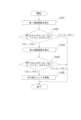
- FIG. 10 is a flowchart of the process of canceling a second level no-passage area.
- the operator selects the no-passage area to be cancelled on the management screen CP and performs the cancellation operation.
- the no-passage cancellation unit 31 displays the first confirmation screen 600 on the display device 23 (step S101).
- a cancellation operation is performed when, for example, the operator selects a second level no-passage area and presses the down cancellation restriction button 410.
- a case where a cancellation operation of a no-passage area is performed also includes a case where the operator receives information from an information terminal used by the operator to cancel the no-passage area to be cancelled.
- step S102 If the no-entry area removal unit 31 detects that the "Yes” button 610 has been pressed on the first confirmation screen 600 (step S102: YES), it displays the second confirmation screen 700 on the display device 23 (step S103). On the other hand, if the no-entry area removal unit 31 detects that the "No" button 620 has been pressed on the first confirmation screen 600 (step S102: NO), it ends the no-entry area removal process.
- step S104 If the no-traffic area removal unit 31 detects that the "Yes" button 710 has been pressed on the second confirmation screen 700 (step S104: YES), it assumes that the operator manager has approved the removal of the no-traffic area and removes the no-traffic area to be removed (step S105). At this time, the no-traffic area removal unit 31 records the information entered in the remarks field 730 in the storage device 20 along with the removal of the no-traffic area, and displays a message screen on the display device 23.
- the no-traffic area removal unit 31 detects that the "No" button 720 has been pressed on the second confirmation screen 700 (step S104: NO), it displays a message on the display device 23 urging the operator manager to approve the removal, and suspends or ends the process of removing the no-traffic area.
- the road ban lifting unit 31 may, as the second confirmation process, request the second user to approve the lifting of the road ban.
- the road ban lifting unit 31 may send information (the above-mentioned approval request) to the manager terminal 4 to confirm whether the operator manager has approved the lifting of the road ban.
- the road ban lifting unit 31 receives information indicating approval (the above-mentioned approval permission notification) from the manager terminal 4, it may lift the prohibited area.
- FIG. 11 is a flowchart of the release process when an approval request is made as the second confirmation process. Note that steps S201 and S202 are similar to steps S101 and S102, and therefore will not be explained.
- step S202 If the no-traffic area removal unit 31 detects that the "Yes” button 610 has been pressed on the first confirmation screen 600 (step S202: “Yes” button), it sends an approval request to the manager terminal 4 (step S203). On the other hand, if the no-traffic area removal unit 31 detects that the "No” button 620 has been pressed on the first confirmation screen 600 (step S202: “No” button), it ends the no-traffic area removal process.
- the manager terminal 4 sends an approval permission notification to the no-traffic area removal unit 31.
- the no-traffic area removal unit 31 receives an approval permission notification from the manager terminal 4 (step S204: YES)
- the no-traffic area removal unit 31 receives an approval denial notification from the manager terminal 4 (step S204: NO)
- it determines that approval was not obtained and ends the process of removing the no-traffic area. Note that when the no-traffic area removal unit 31 receives an approval denial notification from the manager terminal 4, it may display a message on the display device 23 indicating that the operator manager has not approved.
- the restriction on setting a no-passage area is described as requiring the approval of the operator manager, but is not limited to this.
- the restriction on setting a no-passage area may mean that a no-passage area cannot be set regardless of whether the operator manager's approval is obtained.
- the restriction on removing a no-passage area is described as requiring the approval of the operator manager, but is not limited to this.
- the restriction on removing a no-passage area may mean that a no-passage area cannot be removed regardless of whether the operator manager's approval is obtained.
- the no-passage setting unit 30 may determine whether the user who performed the setting operation of the no-passage area (e.g., pressing the route down setting button 300) or the cancellation operation of the no-passage area (e.g., pressing the route down cancellation button 310) is the operator or the operator manager based on the authority information of the logged-in user. Note that the operator manager may log in to the control device 5 using the administrator terminal 4 to set the no-passage area or cancel the no-passage area.
- the control device 5 executes a specific process that includes a process of confirming whether the second user has approved the lifting of the road ban. Then, when the second user has approved the lifting of the road ban, the control device 5 lifts the road ban. With this configuration, the control device 5 can prevent the road ban from being lifted due to an operational error by the user.
- the traveling vehicle system 1 may also be equipped with a mechanical stopper.
- the traveling vehicle system 1 can prevent the no-entry area from being lifted due to an operational error by the user, and therefore can prevent the traveling vehicle from coming into contact with the mechanical stopper when the no-entry area is lifted due to an operational error.
- the second user is not limited to the operator manager, and may be, for example, multiple operators.
- the approval required in the second confirmation process is not limited to the approval of the operator manager, and may be, for example, approval of multiple people.
- the second user may be a different operator as long as it is different from the first user.
- This embodiment discloses the following configuration.
- (Configuration 1) A control device (5) for controlling the running of a running vehicle (3) on a track (2), a traffic prohibition setting unit (30) for setting a predetermined area on the track (2) as a traffic prohibition area; a traffic prohibition release unit (31) that, when a first user performs an operation to release the traffic prohibition area, executes a specific process including a process of confirming whether a second user different from the first user has approved the release of the traffic prohibition area; Equipped with The control device (5), wherein the passage prohibition lifting unit (31) lifts the passage prohibition area when it is confirmed that the second user has approved the lifting of the passage prohibition area.
- the no-passage setting unit (30) sets the predetermined area as the no-passage area when the second user performs a setting operation to instruct the setting of the no-passage area, and when the first user performs the setting operation, sets the no-passage area of the predetermined area on the condition that the setting of the no-passage area is approved by the second user. 2.
- the control device (5) according to configuration 1.
- the no-traffic setting unit (30) displays an input screen having an input field for inputting a reason for setting the no-traffic area on a display device (23), and stores the information inputted in the input field in association with information indicating the no-traffic area in a storage device (20). 3.
- the control device (5) according to configuration 1 or 2.
- the specific processing is a first confirmation process for, when the cancellation operation is performed, displaying on a display device (23) identification information of the second user who performed the setting operation of the prohibited area and a reason for setting the prohibited area, and confirming the first user's intention to cancel the prohibited area; a second confirmation process for confirming whether the second user has approved the cancellation of the no-traffic area when the first confirmation process confirms the first user's intention to cancel the no-traffic area; including, The control device (5) according to any one of configurations 1 to 3.
- the passage prohibition lifting unit (31) displays, on the display device (23), a confirmation screen for confirming whether the second user has approved the lifting of the passage prohibition area, and lifts the passage prohibition area when a predetermined operation is performed on the confirmation screen.
- the control device (5) according to configuration 5 (Configuration 6)
- the passage prohibition lifting unit (31), as the second confirmation process, transmits an approval request for lifting the passage prohibition area by the second user to an information terminal (4) used by the second user, and lifts the passage prohibition area when information indicating approval is received from the information terminal (4).
- the control device (5) according to configuration 5.
- (Configuration 7) Either a first level or a second level can be set for the no-passage area,
- the passage prohibition release unit (31) executes the specific process when the passage prohibition area set to the second level is to be released, and when the passage prohibition area set to the first level is to be released, the specific process is not executed, and the passage prohibition area of the predetermined area set to the first level is released based on the release operation by the first user.
- the traffic prohibition setting unit (30) checks whether a second user different from the first user has approved the setting of the prohibited area, and sets the prohibited area when it is confirmed that the second user has approved the setting of the prohibited area.
Landscapes
- Engineering & Computer Science (AREA)
- Mechanical Engineering (AREA)
- Aviation & Aerospace Engineering (AREA)
- Radar, Positioning & Navigation (AREA)
- Remote Sensing (AREA)
- Physics & Mathematics (AREA)
- General Physics & Mathematics (AREA)
- Automation & Control Theory (AREA)
- Traffic Control Systems (AREA)
- Control Of Driving Devices And Active Controlling Of Vehicle (AREA)
Priority Applications (2)
| Application Number | Priority Date | Filing Date | Title |
|---|---|---|---|
| JP2024552923A JPWO2024090163A1 (https=) | 2022-10-27 | 2023-10-05 | |
| CN202380075574.2A CN120153332A (zh) | 2022-10-27 | 2023-10-05 | 控制装置、行驶车系统及解除方法 |
Applications Claiming Priority (2)
| Application Number | Priority Date | Filing Date | Title |
|---|---|---|---|
| JP2022-172265 | 2022-10-27 | ||
| JP2022172265 | 2022-10-27 |
Publications (1)
| Publication Number | Publication Date |
|---|---|
| WO2024090163A1 true WO2024090163A1 (ja) | 2024-05-02 |
Family
ID=90830686
Family Applications (1)
| Application Number | Title | Priority Date | Filing Date |
|---|---|---|---|
| PCT/JP2023/036328 Ceased WO2024090163A1 (ja) | 2022-10-27 | 2023-10-05 | 制御装置、走行車システム、及び解除方法 |
Country Status (4)
| Country | Link |
|---|---|
| JP (1) | JPWO2024090163A1 (https=) |
| CN (1) | CN120153332A (https=) |
| TW (1) | TW202419379A (https=) |
| WO (1) | WO2024090163A1 (https=) |
Citations (3)
| Publication number | Priority date | Publication date | Assignee | Title |
|---|---|---|---|---|
| JP2017010110A (ja) * | 2015-06-17 | 2017-01-12 | 日立建機株式会社 | 管制制御システム、管制制御装置、及び車載端末装置 |
| JP2017228126A (ja) * | 2016-06-23 | 2017-12-28 | 日本車輌製造株式会社 | 搬送車の走行管理プログラム |
| JP2018156436A (ja) * | 2017-03-17 | 2018-10-04 | 株式会社デンソー | 走行制御システム、走行制御プログラム及び自動走行車両 |
-
2023
- 2023-10-05 CN CN202380075574.2A patent/CN120153332A/zh active Pending
- 2023-10-05 WO PCT/JP2023/036328 patent/WO2024090163A1/ja not_active Ceased
- 2023-10-05 JP JP2024552923A patent/JPWO2024090163A1/ja active Pending
- 2023-10-24 TW TW112140516A patent/TW202419379A/zh unknown
Patent Citations (3)
| Publication number | Priority date | Publication date | Assignee | Title |
|---|---|---|---|---|
| JP2017010110A (ja) * | 2015-06-17 | 2017-01-12 | 日立建機株式会社 | 管制制御システム、管制制御装置、及び車載端末装置 |
| JP2017228126A (ja) * | 2016-06-23 | 2017-12-28 | 日本車輌製造株式会社 | 搬送車の走行管理プログラム |
| JP2018156436A (ja) * | 2017-03-17 | 2018-10-04 | 株式会社デンソー | 走行制御システム、走行制御プログラム及び自動走行車両 |
Also Published As
| Publication number | Publication date |
|---|---|
| JPWO2024090163A1 (https=) | 2024-05-02 |
| TW202419379A (zh) | 2024-05-16 |
| CN120153332A (zh) | 2025-06-13 |
Similar Documents
| Publication | Publication Date | Title |
|---|---|---|
| JP6658466B2 (ja) | 行先階取得装置、エレベータシステム、情報端末、プログラム | |
| KR100760226B1 (ko) | 엘리베이터의 시큐리티 시스템 | |
| CN105189325B (zh) | 外围设备近场通信(nfc)读卡器 | |
| US7404469B2 (en) | Elevator call registration device | |
| JP7348886B2 (ja) | エレベーター管理システム及びエレベーター運行管理システム | |
| JP6301513B1 (ja) | エレベータの群管理システム | |
| US8776954B2 (en) | Car destination floor indication device | |
| EP3530602B1 (en) | Safety circuit for an elevator system, device and method of updating such a safety circuit | |
| CN106006240A (zh) | 电梯系统及无线通信方法 | |
| WO2024090163A1 (ja) | 制御装置、走行車システム、及び解除方法 | |
| JP2021138507A (ja) | エレベーターシステム及びエレベーター制御方法 | |
| JP2013225233A (ja) | 仮想計算機システム、仮想計算機システムにおけるユーザ認証方法、プログラム、および集積回路 | |
| JP6512251B2 (ja) | 乗り場行先階登録システムを具えるエレベータ | |
| JP2006256830A (ja) | エレベータシステム | |
| CN106185521B (zh) | 电梯系统 | |
| CN109110600B (zh) | 电梯的出入口联动系统和群管理控制方法 | |
| WO2021111722A1 (ja) | エレベーターの通常運転復帰装置および通常運転復帰方法 | |
| JP6828793B1 (ja) | エレベータの制御システム | |
| JP4672295B2 (ja) | エレベータの保守装置 | |
| JP7733223B2 (ja) | 非接触操作盤制御装置、エレベーター及び非接触操作盤の制御方法 | |
| JP2022025770A (ja) | エレベータの制御システム | |
| JPWO2024090163A5 (https=) | ||
| US12555429B2 (en) | Access control device with gateway operability | |
| KR102848396B1 (ko) | 이중 입고 및 오적재 사고 위험을 방지하는 무인운반로봇을 운용하는 방법 및 장치 | |
| JP7488173B2 (ja) | エレベーターシステム及びエレベーター制御方法 |
Legal Events
| Date | Code | Title | Description |
|---|---|---|---|
| 121 | Ep: the epo has been informed by wipo that ep was designated in this application |
Ref document number: 23882372 Country of ref document: EP Kind code of ref document: A1 |
|
| WWE | Wipo information: entry into national phase |
Ref document number: 2024552923 Country of ref document: JP Ref document number: 202380075574.2 Country of ref document: CN |
|
| NENP | Non-entry into the national phase |
Ref country code: DE |
|
| WWP | Wipo information: published in national office |
Ref document number: 202380075574.2 Country of ref document: CN |
|
| 122 | Ep: pct application non-entry in european phase |
Ref document number: 23882372 Country of ref document: EP Kind code of ref document: A1 |