WO2024089933A1 - ロータ部材、ロータ、回転電気機械、ブラシレスモータ、及び、ロータ部材の製造方法 - Google Patents
ロータ部材、ロータ、回転電気機械、ブラシレスモータ、及び、ロータ部材の製造方法 Download PDFInfo
- Publication number
- WO2024089933A1 WO2024089933A1 PCT/JP2023/022482 JP2023022482W WO2024089933A1 WO 2024089933 A1 WO2024089933 A1 WO 2024089933A1 JP 2023022482 W JP2023022482 W JP 2023022482W WO 2024089933 A1 WO2024089933 A1 WO 2024089933A1
- Authority
- WO
- WIPO (PCT)
- Prior art keywords
- magnetic body
- rotor member
- soft magnetic
- hard magnetic
- face
- Prior art date
- Legal status (The legal status is an assumption and is not a legal conclusion. Google has not performed a legal analysis and makes no representation as to the accuracy of the status listed.)
- Ceased
Links
Images








Classifications
-
- H—ELECTRICITY
- H02—GENERATION; CONVERSION OR DISTRIBUTION OF ELECTRIC POWER
- H02K—DYNAMO-ELECTRIC MACHINES
- H02K1/00—Details of the magnetic circuit
- H02K1/06—Details of the magnetic circuit characterised by the shape, form or construction
- H02K1/22—Rotating parts of the magnetic circuit
- H02K1/27—Rotor cores with permanent magnets
- H02K1/2706—Inner rotors
- H02K1/272—Inner rotors the magnetisation axis of the magnets being perpendicular to the rotor axis
- H02K1/2726—Inner rotors the magnetisation axis of the magnets being perpendicular to the rotor axis the rotor consisting of a single magnet or two or more axially juxtaposed single magnets
- H02K1/2733—Annular magnets
-
- H—ELECTRICITY
- H02—GENERATION; CONVERSION OR DISTRIBUTION OF ELECTRIC POWER
- H02K—DYNAMO-ELECTRIC MACHINES
- H02K15/00—Processes or apparatus specially adapted for manufacturing, assembling, maintaining or repairing of dynamo-electric machines
- H02K15/02—Processes or apparatus specially adapted for manufacturing, assembling, maintaining or repairing of dynamo-electric machines of stator or rotor bodies
- H02K15/03—Processes or apparatus specially adapted for manufacturing, assembling, maintaining or repairing of dynamo-electric machines of stator or rotor bodies having permanent magnets
Definitions
- the present invention relates to a rotor member for use in a rotating electric machine, a rotor including a rotor member, a rotating electric machine including a rotor member, a brushless motor including a rotor member, and a method for manufacturing a rotor member for use in a rotating electric machine.
- a known example of an invention relating to a conventional rotor member is the motor rotor described in Patent Document 1.
- the motor rotor described in Patent Document 1 includes a soft magnetic yoke portion and a magnet portion.
- the material of the soft magnetic yoke portion is soft magnetic powder containing a binder.
- the material of the magnet portion is magnetic powder containing a binder.
- the soft magnetic powder containing a binder and the magnetic powder containing a binder are molded integrally.
- the object of the present invention is to provide a rotor member, a rotor, a rotating electric machine, a brushless motor, and a method for manufacturing a rotor member that can improve the fixing strength between a soft magnetic body and a hard magnetic body.
- a rotor member includes: A rotor member for use in a rotating electrical machine, comprising: A soft magnetic body which is a cylindrical compact formed from soft magnetic powder and has a first end face facing a first direction along a central axis of the soft magnetic body and a second end face facing a second direction opposite to the first direction; a hard magnetic body that is a cylindrical compact formed from hard magnetic powder, the hard magnetic body having a third end face facing the first direction and a fourth end face facing the second direction, the hard magnetic body being in contact with an outer peripheral surface or an inner peripheral surface of the soft magnetic body in a radial direction centered on the central axis; Equipped with a contact surface between the soft magnetic body and the hard magnetic body has a shape that protrudes in the opposite direction to the radial direction when the hard magnetic body contacts the outer circumferential surface of the soft magnetic body, or has a shape that protrudes in the radial direction when the hard magnetic body contacts the inner circumferential surface of the soft magnetic body,
- a soft magnetic body which is
- a method for manufacturing a rotor member includes the steps of: A rotor member for use in a rotating electrical machine, comprising: a soft magnetic body having a cylindrical shape and a first end face facing a first direction along a central axis of the soft magnetic body and a second end face facing a second direction opposite to the first direction; a hard magnetic body having a cylindrical shape, a third end surface facing the first direction and a fourth end surface facing the second direction, and in contact with an outer peripheral surface or an inner peripheral surface of the soft magnetic body in a radial direction centered on the central axis; Equipped with A method for manufacturing a rotor member, comprising the steps of: a temporary hard magnetic body forming step of compressing and molding a hard magnetic powder obtained by mixing the isotropic magnet powder and the first binder powder to form a temporary hard magnetic body; a filling step of filling a mold with soft magnetic powder obtained by mixing iron powder and second binder powder and the temporary hard magnetic body after the temporary hard magnetic body
- the present invention provides a rotor member, rotor, rotating electric machine, brushless motor, and method for manufacturing a rotor member that can improve the fixing strength between a soft magnetic body and a hard magnetic body.
- FIG. 1 is a perspective view of a rotor 10.
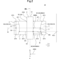
- FIG. 2 is a cross-sectional view of the rotor 10 taken along line AA.
- FIG. 3 is a flow chart showing an example of a method for manufacturing the rotor member 1.
- FIG. 4 is a cross-sectional view taken along line AA, showing an example of a manufacturing process for the rotor member 1.
- FIG. 5 is a cross-sectional view taken along line AA, showing an example of a manufacturing process for the rotor member 1.
- FIG. 6 is a cross-sectional view taken along line AA, showing an example of a manufacturing process for the rotor member 1.
- FIG. 7 is a cross-sectional view taken along line AA, showing an example of a manufacturing process for the rotor member 1.
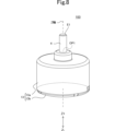
- FIG. 8 is a perspective view showing the appearance of a brushless motor 100 in which the rotor member 1 is used.
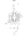
- FIG. 9 is an exploded perspective view of a brushless motor 100 in which the rotor member 1 is used.
- FIG. 10 is a cross-sectional view taken along line AA of the rotor 20 according to the comparative example.
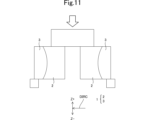
- FIG. 11 is a model diagram of a shear test of the rotor member 1.
- FIG. 12 is a model diagram of a shear test of the rotor member 6 according to the comparative example.
- FIG. 13 shows the results of shear tests on the rotor member 1 and the rotor member 6 according to the comparative example.
- FIG. 14 is a cross-sectional view of the rotor 10a taken along line AA.
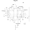
- FIG. 15 is a cross-sectional view of the rotor 10b taken along line AA.
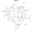
- FIG. 16 is a cross-sectional view of the rotor 10c taken along line AA.
- FIG. 17 is a cross-sectional view of the rotor 10d taken along line AA.
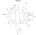
- FIG. 18 is a cross-sectional view of the rotor 10e taken along line AA.
- FIG. 19 is a cross-sectional view of the rotor 10f taken along line AA.
- Fig. 1 is a perspective view of the rotor 10.
- Fig. 2 is a cross-sectional view of the rotor 10 taken along line AA.
- the rotor 10 is used in a brushless motor 100, which will be described later.
- the brushless motor 100 is an example of a "rotating electric machine" according to the present invention.
- the rotor 10 includes a shaft 4 and a rotor member 1, as shown in FIG. 1.
- the shaft 4 has a shape that extends in the Z+ direction, which is the positive direction of the Z axis. More specifically, the shaft 4 is cylindrical.
- the central axis of the shaft 4 is the Z axis.
- the shaft 4 also includes a first end E1 and a second end E2.
- the first end E1 is located in the Z+ direction from the end of the rotor member 1 in the Z+ direction.
- the second end E2 is located in the Z- direction from the end of the rotor member 1 in the Z- direction, which is the negative direction of the Z axis.
- the Z- direction is the opposite direction to the Z+ direction.
- the Z+ direction corresponds to the "first direction” of the present invention.
- the Z- direction corresponds to the "second direction” of the present invention.
- the Z+ direction and the Z- direction are each along the Z axis.
- the rotor member 1 includes a soft magnetic body 2 and a hard magnetic body 3.
- the rotor member 1 is cylindrical.
- the central axis of the rotor member 1 is the Z-axis. In other words, the central axis of the rotor member 1 coincides with the central axis of the shaft 4.
- the rotor member 1 is also arranged so that the inner edge of the rotor member 1 coincides with the outer edge of the shaft 4 when viewed in the Z-direction.
- the outer peripheral surface OS4 of the shaft 4 in the radial direction centered on the Z-axis contacts the inner peripheral surface IS1 of the rotor member 1 in the radial direction centered on the Z-axis, as shown in FIG. 2.
- the soft magnetic body 2 is cylindrical as shown in FIG. 1.
- the central axis of the soft magnetic body 2 is the Z-axis. That is, the central axis of the soft magnetic body 2 coincides with the central axis of the shaft 4.
- the inner edge and the outer edge of the soft magnetic body 2 as viewed in the Z-direction are each circular.
- the soft magnetic body 2 is arranged so that the inner edge of the soft magnetic body 2 coincides with the outer edge of the shaft 4 as viewed in the Z-direction. That is, the outer peripheral surface OS4 of the shaft 4 in the radial direction centered on the Z-axis comes into contact with the inner peripheral surface IS2 of the soft magnetic body 2 in the radial direction centered on the Z-axis as shown in FIG. 2. As a result, the soft magnetic body 2 comes into contact with the outer peripheral surface OS4 of the shaft 4 in the radial direction centered on the Z-axis.
- the soft magnetic body 2 has a first end face EF1 and a second end face EF2. More specifically, the first end face EF1 is located at the end of the soft magnetic body 2 in the Z+ direction. The first end face EF1 faces the Z+ direction. That is, the normal direction of the first end face EF1 is the Z+ direction.
- the second end face EF2 is located at the end of the soft magnetic body 2 in the Z- direction. The second end face EF2 faces the Z- direction. That is, the normal direction of the second end face EF2 is the Z- direction.
- the inner edge of the first end face EF1 viewed in the Z- direction and the outer edge of the first end face EF1 viewed in the Z- direction, as well as the inner edge of the second end face EF2 viewed in the Z+ direction and the outer edge of the second end face EF2 viewed in the Z+ direction, are each circular.
- the soft magnetic body 2 is a soft magnetic body. When an external magnetic field is applied to the soft magnetic body, the soft magnetic body is magnetized. When the application of the magnetic field is then stopped, the soft magnetic body loses its magnetization.
- An example of the material of such a soft magnetic body is iron.
- the soft magnetic body 2 is a molded body formed from soft magnetic powder 21.
- the material of the soft magnetic powder 21 includes, for example, iron and a binder. Iron is an example of a soft magnetic material.
- the binder is, for example, a resin.
- the soft magnetic powder 21 is, for example, a mixture of iron powder and epoxy resin powder, which is an example of a binder powder. The method of forming the soft magnetic body 2 will be described later.
- the hard magnetic body 3 is cylindrical as shown in FIG. 1.
- the central axis of the hard magnetic body 3 is the Z-axis. That is, the central axis of the hard magnetic body 3 coincides with the central axis of the shaft 4.
- the inner edge and the outer edge of the hard magnetic body 3 as viewed in the Z-direction are each circular.
- the hard magnetic body 3 is arranged so that the inner edge of the hard magnetic body 3 coincides with the outer edge of the soft magnetic body 2 as viewed in the Z-direction.
- the inner peripheral surface IS3 of the hard magnetic body 3 in the radial direction centered on the Z-axis comes into contact with the outer peripheral surface OS2 of the soft magnetic body 2 in the radial direction centered on the Z-axis as shown in FIG. 2.
- the hard magnetic body 3 comes into contact with the outer peripheral surface OS2 of the soft magnetic body 2 in the radial direction centered on the Z-axis.
- the hard magnetic body 3 does not come into contact with the inner peripheral surface IS2 of the soft magnetic body 2 in the radial direction centered on the Z-axis as shown in FIG. 1 and FIG. 2.
- the hard magnetic body 3 has a third end face EF3 and a fourth end face EF4. More specifically, the third end face EF3 is located at the end of the hard magnetic body 3 in the Z+ direction. The third end face EF3 faces the Z+ direction. That is, the normal direction of the third end face EF3 is the Z+ direction. The fourth end face EF4 is located at the end of the hard magnetic body 3 in the Z- direction. The fourth end face EF4 faces the Z- direction. That is, the normal direction of the fourth end face EF4 is the Z- direction.
- the inner edge of the third end face EF3 viewed in the Z- direction and the outer edge of the third end face EF3 viewed in the Z- direction, as well as the inner edge of the fourth end face EF4 viewed in the Z+ direction and the outer edge of the fourth end face EF4 viewed in the Z+ direction, are each circular.
- Hard magnetic body 3 is a hard magnetic body. When a magnetic field is applied from the outside, the hard magnetic body is magnetized. Even if the application of the magnetic field is then stopped, the hard magnetic body does not lose its magnetization. Such a hard magnetic material is a magnet.
- the hard magnetic body 3 is a molded body formed from hard magnetic powder 31.
- the material of the hard magnetic powder 31 includes, for example, a magnet and a binder.
- the magnet is, for example, a rare earth magnet such as a neodymium magnet.
- the binder is, for example, a resin.
- the hard magnetic powder 31 is, for example, a mixture of neodymium magnet powder and epoxy resin powder, which is an example of binder powder. The method of forming the hard magnetic body 3 will be described later.
- the position in the Z+ direction of the first end face EF1 of the soft magnetic body 2 is equal to the position in the Z+ direction of the third end face EF3 of the hard magnetic body 3.
- the position in the Z+ direction of the second end face EF2 of the soft magnetic body 2 is equal to the position in the Z+ direction of the fourth end face EF4 of the hard magnetic body 3.
- the entire outer peripheral surface OS2 of the soft magnetic body 2 in the radial direction centered on the Z axis is in surface contact with the entire inner peripheral surface IS3 of the hard magnetic body 3 in the radial direction centered on the Z axis, as shown in Figures 1 and 2. Therefore, in this embodiment, the outer peripheral surface OS2 of the soft magnetic body 2 in the radial direction centered on the Z axis and the inner peripheral surface IS3 of the hard magnetic body 3 in the radial direction centered on the Z axis are each defined as the contact surface CS between the soft magnetic body 2 and the hard magnetic body 3.
- the contact surface CS between the soft magnetic body 2 and the hard magnetic body 3 has a shape that protrudes in the centripetal direction DIRC when the hard magnetic body 3 contacts the outer peripheral surface OS2 of the soft magnetic body 2.
- the centripetal direction DIRC is the opposite radial direction centered on the Z axis.
- the centripetal direction DIRC is a direction that is perpendicular to the Z axis and faces the Z axis when viewed in the Z+ direction or the Z- direction.
- the centripetal direction DIRC is a direction that faces the Z axis when viewed in the Z+ direction or the Z- direction.
- the contact surface CS between the soft magnetic body 2 and the hard magnetic body 3 has a curved shape that protrudes in the centripetal direction DIRC. Furthermore, the contact surface CS between the soft magnetic body 2 and the hard magnetic body 3 is a curved surface and does not include a flat surface.
- the position of the centripetal direction DIRC of the contact surface CS between the soft magnetic body 2 and the hard magnetic body 3 is non-uniform in the Z+ direction, as shown in Figure 2.
- the width W in the radial direction centered on the Z axis of the portion (outer peripheral surface OS2) that constitutes the contact surface CS within the soft magnetic body 2 is non-uniform in the Z+ direction.
- the width W in the radial direction centered on the Z axis of the portion constituting the contact surface CS in the soft magnetic body 2 is, in other words, the distance in the centripetal direction DIRC (e.g., distances WC, DC in FIG. 2) between the inner circumferential surface IS2 and the outer circumferential surface OS2 at the position in the Z+ direction where the soft magnetic body 2 is present (e.g., first position PO1 in FIG. 2), when there is no member (e.g., shaft 4 in FIG. 2) or space between the inner circumferential surface IS2 and the outer circumferential surface OS2 at the first position PO1 (e.g., distance WC in FIG. 2).
- DIRC centripetal direction
- DIRC distances WC, DC in FIG. 2
- the position in the Z+ direction where the width W is the minimum width WMIN is a position different from the Z+ direction position of the first end face EF1, the Z+ direction position of the second end face EF2, the Z+ direction position of the third end face EF3, and the Z+ direction position of the fourth end face EF4.
- there is only one Z+ direction position where the width W is the minimum and it is a position equal to the Z+ direction position of the intermediate face IS.
- the Z+ direction position where the width W is the minimum is only the Z+ direction position of the intermediate face IS.
- the intermediate face IS is a plane whose Z+ direction distance D1 from the third end face EF3 of the hard magnetic body 3 is equal to the distance D2 from the fourth end face EF4 of the hard magnetic body 3.
- Such an intermediate face IS is a plane perpendicular to the Z axis because the normal direction of the third end face EF3 is the Z+ direction and the normal direction of the fourth end face EF4 is the Z- direction.
- the soft magnetic body 2 has the following configuration.
- the position of the third end face EF3 in the Z+ direction is equal to the position of the first end face EF1 in the Z+ direction.
- Fig. 3 is a flow chart showing an example of the manufacturing method of the rotor member 1.
- Fig. 4 is a cross-sectional view taken along line A-A showing an example of the manufacturing process of the rotor member 1.
- Fig. 5 is a cross-sectional view taken along line A-A showing an example of the manufacturing process of the rotor member 1.
- Fig. 6 is a cross-sectional view taken along line A-A showing an example of the manufacturing process of the rotor member 1.
- Fig. 7 is a cross-sectional view taken along line A-A showing an example of the manufacturing process of the rotor member 1.
- hard magnetic powder 31 is filled between the inner punch IP and the outer die ODI, which is a part of the mold DI, in the Z+ direction from the outer punch OP (FIG. 3: step S11). More specifically, the hard magnetic powder 31 is, for example, a mixture of neodymium magnet powder and epoxy resin powder.
- the neodymium magnet powder is an example of the "rare earth magnet powder” and “isotropic magnet powder” of the present invention.
- the epoxy resin powder is an example of the "resin” and "first binder powder” of the present invention.
- the inner punch IP, outer punch OP, and outer die ODI are each cylindrical.
- the central axis of each of the inner punch IP, outer punch OP, and outer die ODI is the Z-axis.
- the outer punch OP is disposed in the centripetal direction DIRC from the outer die ODI.
- the inner punch IP is disposed in the centripetal direction DIRC from the outer punch OP.
- the outer peripheral surface OSOP of the outer punch OP in the radial direction about the Z-axis contacts the inner peripheral surface ISODI of the outer die ODI in the radial direction about the Z-axis.
- the outer peripheral surface OSIP of the inner punch IP in the radial direction about the Z-axis contacts the inner peripheral surface ISOP of the outer punch OP in the radial direction about the Z-axis.
- the inner punch IP and outer punch OP are each movable in the Z+ direction and the Z- direction.
- the die DI includes the outer die ODI and the inner die IDI described above.
- the inner die IDI is cylindrical.
- the central axis of the inner die IDI is the Z-axis.
- the inner die IDI is disposed in the centripetal direction DIRC from the inner punch IP.
- the outer peripheral surface OSIDI of the inner die IDI in the radial direction centered on the Z-axis contacts the inner peripheral surface ISIP of the inner punch IP in the radial direction centered on the Z-axis.
- the filled hard magnetic powder 31 is compressed in the Z- direction by an outer punch OP that is positioned in the Z- direction from the hard magnetic powder 31, and a punch P that is positioned in the Z+ direction from the hard magnetic powder 31.
- the Z- direction end face of punch P faces the Z- direction. In other words, the normal direction of the Z- direction end face of punch P is the Z- direction.
- the pressure applied to the hard magnetic powder 31 is, for example, 300 MPa.
- the hard magnetic powder 31 is compression molded to form the temporary hard magnetic body 32 (FIG. 3: step S12, temporary hard magnetic body forming process). More specifically, the radial thickness of the temporary hard magnetic body 32 around the Z axis is uniform in the Z+ direction.
- the soft magnetic powder 21 and temporary hard magnetic body 32 are filled into the mold DI so that they are aligned in the radial direction around the Z axis and in contact with each other (FIG. 3: step S13, filling process).
- the soft magnetic powder 21 is, for example, a mixture of iron powder and epoxy resin powder.
- the epoxy resin powder is an example of each of the "resin” and "second binder powder" of the present invention.
- the filled soft magnetic powder 21 and temporary hard magnetic body 32 are pressed in the Z- direction by the inner punch IP and outer punch OP, which are disposed in the Z- direction relative to the soft magnetic powder 21 and temporary hard magnetic body 32, respectively, and the punch P, which is disposed in the Z+ direction relative to the soft magnetic powder 21 and temporary hard magnetic body 32, respectively, as shown in FIG. 7.
- the pressure applied to the temporary hard magnetic body 32 is greater than the pressure applied to the soft magnetic powder 21.
- the pressure applied to the temporary hard magnetic body 32 is, for example, 800 MPa.
- the soft magnetic powder 21 and temporary hard magnetic body 32 are compression molded from the Z+ direction to form a permanently molded body.
- the formed permanently molded body is thermally cured to form the rotor member 1 (FIG. 3: step S14, rotor member forming step).
- the Z+ direction position of the Z+ direction end face of the inner punch IP is equal to the Z+ direction position of the Z+ direction end face of the outer punch OP.
- the Z+ direction position of the second end face EF2 of the soft magnetic body 2 can be equal to the Z+ direction position of the fourth end face EF4 of the hard magnetic body 3 by adjusting the Z+ direction position of the Z+ direction end face of the inner punch IP and the Z+ direction position of the Z+ direction end face of the outer punch OP.
- the soft magnetic powder 21 and the provisional hard magnetic body 32 are integrally molded in the Z- direction by the punch P whose Z- direction end face faces the Z- direction, so that the Z+ direction position of the first end face EF1 of the soft magnetic body 2 can be equal to the Z+ direction position of the third end face EF3 of the hard magnetic body 3.
- the pressure required to form the hard magnetic body 3 is greater than the pressure required to form the soft magnetic body 2.
- the pressure conditions average pressure, pressure distribution, pressure time, etc.
- the pressure for pressing the soft magnetic powder 21 and the provisional hard magnetic body 32 is greater than the pressure required to form the soft magnetic body 2 and less than the pressure required to form the hard magnetic body 3, so that the hard magnetic body 3 can be inserted in the centripetal direction DIRC (for example, region A1 in FIG. 2) while forming the soft magnetic body 2.
- DIRC centripetal direction
- Fig. 8 is an external perspective view of the brushless motor 100 using the rotor member 1.
- Fig. 9 is an exploded perspective view of the brushless motor 100 using the rotor member 1. Note that in Fig. 9, reference symbols are given only to representative teeth 14b, coils 15, and insulating members 16 out of the plurality of teeth 14b, the plurality of coils 15, and the plurality of insulating members 16.
- the brushless motor 100 includes a stator assembly 11, a shaft 4, and a rotor member 1. As shown in Figure 9, the stator assembly 11 is disposed around the rotor 10 when viewed in the Z-direction. In other words, the brushless motor 100 is an inner rotor type.
- the stator assembly 11 includes a bearing 12, a housing 13, a magnetic core 14, a number of coils 15, and a number of insulating members 16.
- the bearing 12 supports the shaft 4 so that it can rotate in the circumferential direction around the Z-axis. More specifically, as shown in FIG. 9, the bearing 12 has a first bearing 12a and a second bearing 12b. Each of the first bearing 12a and the second bearing 12b is cylindrical. The central axis of each of the first bearing 12a and the second bearing 12b is the Z-axis. The central axis of each of the first bearing 12a and the second bearing 12b coincides with the central axis of the shaft 4.
- the first bearing 12a is located in the +Z direction from the second bearing 12b.
- the first bearing 12a is also located in the +Z direction from the rotor member 1.
- the second bearing 12b is located in the -Z direction from the rotor member 1.
- the second bearing 12b supports the second end E2 of the shaft 4.
- the housing 13 has a first housing 13a and a second housing 13b.
- the first housing 13a is cylindrical.
- the central axis of the first housing 13a is the Z-axis.
- the second housing 13b is located in the Z- direction from the first housing 13a.
- the first housing 13a also has an opening OP1.
- the first end E1 of the shaft 4 protrudes from the opening OP1 in the Z+ direction.
- the brushless motor 100 is a single-shaft type.
- the first housing 13a supports the first bearing 12a, the magnetic core 14, the multiple coils 15, and the multiple insulating members 16.
- the second housing 13b supports the second bearing 12b.
- the materials of the first housing 13a and the second housing 13b are, for example, a highly rigid material such as SUS.
- the magnetic core 14 is a soft magnetic material. As shown in FIG. 9, the magnetic core 14 is produced by stacking electromagnetic steel sheets.
- the magnetic core 14 has a cylindrical core back portion 14a and multiple teeth portions 14b.
- the central axis of the core back portion 14a is the Z-axis.
- the nine teeth portions 14b are arranged in a circumferential direction centered on the Z-axis.
- Each of the nine teeth portions 14b extends from the inner surface of the core back portion 14a in the opposite radial direction centered on the Z-axis.
- the outer surface of the magnetic core 14 is insulated.
- the magnetic core 14 is magnetized by both the magnetic field generated by the hard magnetic material 3 and the magnetic field generated by the coil 15 described later.
- the number of coils 15 and insulating members 16 is nine. Each of the nine coils 15 and each of the nine insulating members 16 is provided corresponding to each of the nine teeth 14b. More specifically, if a set including one teeth 14b, one coil 15, and one insulating member 16 is considered to be one set, the nine sets are lined up in the circumferential direction centered on the Z axis. Each set is disposed around the hard magnetic body 3 with a gap therebetween. Note that each set has the same structure. Therefore, a set including one teeth 14b, one coil 15, and one insulating member 16 will be described.
- the coil 15 is wound around the teeth 14b so as to be positioned around the teeth 14b when viewed in the radial direction centered on the Z-axis.
- the coil 15 is made of a conductive material such as copper.
- the coil 15 has a structure in which the surface of the copper wire is covered with an insulating film. The coil 15 generates a magnetic field when a current flows through the coil 15.
- the insulating member 16 is an insulator. As shown in FIG. 9, the insulating member 16 is disposed between the magnetic core 14 and the coil 15. This electrically insulates the magnetic core 14 and the coil 15.
- the coil 15 is supplied with current from a power source (not shown).
- the rotation of the rotor 10 is controlled by controlling this current.
- Fig. 10 is a cross-sectional view of the rotor 20 according to the comparative example taken along line A-A.
- Fig. 11 is a model diagram of the shear test on the rotor member 1.
- Fig. 12 is a model diagram of the shear test on the rotor member 6 according to the comparative example.
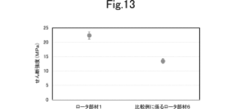
- Fig. 13 shows the results of the shear test on the rotor member 1 and the rotor member 6 according to the comparative example.
- the rotor 20 according to the comparative example will be described. Note that for the rotor 20 according to the comparative example, only the parts that are different from the rotor 10 will be described, and the rest will be omitted.
- the position of the centripetal direction DIRC of the contact surface CS between the soft magnetic body 2 and the hard magnetic body 3 is uniform in the Z+ direction, as shown in FIG. 10. Therefore, in the rotor 20 according to the comparative example, the contact surface CS between the soft magnetic body 2 and the hard magnetic body 3 does not have a shape that protrudes in the centripetal direction DIRC.
- the shear strength of the contact surface CS between the soft magnetic body 2 and the hard magnetic body 3 is used as an index of the fixing strength between the soft magnetic body 2 and the hard magnetic body 3.
- the shear strength of the contact surface CS between the soft magnetic body 2 and the hard magnetic body 3 in the rotor member 1 is greater than the shear strength of the contact surface CS between the soft magnetic body 2 and the hard magnetic body 3 in the rotor member 6 according to the comparative example, as shown in FIG. 13. More specifically, the shear strength of the contact surface CS between the soft magnetic body 2 and the hard magnetic body 3 in the rotor member 6 according to the comparative example is 20 MPa or less, which is practically required for the rotor 10 of a rotating electric machine, whereas the shear strength of the contact surface CS between the soft magnetic body 2 and the hard magnetic body 3 in the rotor member 1 is 20 MPa or more. In this way, the rotor member 1 can improve the shear strength of the contact surface CS between the soft magnetic body 2 and the hard magnetic body 3. As a result, the rotor member 1 can improve the fixing strength between the soft magnetic body 2 and the hard magnetic body 3.
- the rotor member 1 can further improve the fixing strength between the soft magnetic body 2 and the hard magnetic body 3. More specifically, the contact surface CS between the soft magnetic body 2 and the hard magnetic body 3 in the rotor member 1 has a curved shape that protrudes in the centripetal direction DIRC. Therefore, the area of the contact surface CS between the soft magnetic body 2 and the hard magnetic body 3 can be increased. As a result, the rotor member 1 can further improve the fixing strength between the soft magnetic body 2 and the hard magnetic body 3.
- the rotor member 1 makes it easier to obtain the desired magnetic properties with fewer soft magnetic bodies. More specifically, the position in the Z+ direction where the width W in the radial direction around the Z-axis of the portion constituting the contact surface CS is minimum is equal to the position of the intermediate surface IS in the Z+ direction.
- the intermediate surface IS is a surface where the distance D1 in the Z+ direction from the third end surface EF3 of the hard magnetic body 3 is equal to the distance D2 from the fourth end surface EF4 of the hard magnetic body 3. This makes it easier to make the position in the Z+ direction where the width in the radial direction around the Z-axis of the hard magnetic body 3 is maximum equal to the position of the intermediate surface IS in the Z+ direction. Therefore, it is easier to suppress leakage flux among the magnetic flux generated by the hard magnetic body 3. As a result, the rotor member 1 makes it easier to obtain the desired magnetic properties with fewer soft magnetic bodies.
- the rotor member 1 makes it easier to obtain the desired magnetic characteristics with fewer soft magnetic bodies. More specifically, there only needs to be one position in the Z+ direction where the permeance value for the magnetic flux generated by the hard magnetic body 3 is maximum. Therefore, there is only one position in the Z+ direction where the width W in the radial direction about the Z axis of the portion constituting the contact surface CS is minimum. Therefore, the rotor member 1 makes it possible to effectively utilize the soft magnetic bodies. As a result, the rotor member 1 makes it easier to obtain the desired magnetic characteristics with fewer soft magnetic bodies.
- the rotor member 1 makes it easier to obtain the desired magnetic characteristics with less soft magnetic material. More specifically, the distribution of the permeance value for the magnetic flux generated by the hard magnetic material 3 with respect to the position in the Z+ direction is continuous. Thus, the contact surface CS is a curved surface and does not include a flat surface. Therefore, the rotor member 1 makes it possible to effectively utilize the soft magnetic material by continuously changing the shape of the soft magnetic material 2 in accordance with the change in the permeance value for the magnetic flux generated by the hard magnetic material 3 with respect to the position in the Z+ direction. As a result, the rotor member 1 makes it easier to obtain the desired magnetic characteristics with less soft magnetic material.
- the rotor member 1 can be manufactured by the manufacturing method of the rotor member 1 according to the first embodiment of the present invention. More specifically, in the temporary hard magnetic body forming process, the hard magnetic powder 31, which is a mixture of isotropic magnet powder and a first binder powder, is compressed and molded to form the temporary hard magnetic body 32. In the filling process after the temporary hard magnetic body forming process, the soft magnetic powder 21, which is a mixture of iron powder and a second binder powder, and the temporary hard magnetic body 32 are filled into the mold DI so that they are aligned in the radial direction centered on the Z axis and contact each other.
- the hard magnetic powder 31 which is a mixture of isotropic magnet powder and a first binder powder
- the soft magnetic powder 21 and the temporary hard magnetic body 32 are compression molded from the Z+ direction to form the rotor member 1.
- the pressure applied to the temporary hard magnetic body 32 is greater than the pressure applied to the soft magnetic powder 21. This forms the actual molded body.
- the rotor member 1 can be manufactured by the manufacturing method of the rotor member 1 according to the first embodiment of the present invention.
- the manufacturing method of the rotor member 1 according to the first embodiment of the present invention makes it easier to manufacture the rotor member 1. More specifically, the pressure required to form the soft magnetic body 2 is smaller than the pressure required to form the hard magnetic body 3. Therefore, when the soft magnetic powder 21 and the temporary hard magnetic body 32 are pressed from the Z+ direction, a period is provided in which the pressure for pressing the soft magnetic powder 21 and the temporary hard magnetic body 32 is greater than the pressure required to form the soft magnetic body 2 and less than the pressure required to form the hard magnetic body 3. This allows the hard magnetic body 3 to enter the centripetal direction DIRC while forming the soft magnetic body 2. Therefore, the contact surface CS between the soft magnetic body 2 and the hard magnetic body 3 can be shaped to protrude in the centripetal direction DIRC. As a result, the manufacturing method of the rotor member 1 according to the first embodiment of the present invention makes it easier to manufacture the rotor member 1.
- FIG. 14 is a cross-sectional view of the rotor 10a taken along line A-A.
- the rotor member 1a according to the first modified example only the differences from the rotor member 1 according to the first embodiment will be described, and the rest will be omitted.
- rotor member 1a differs from rotor member 1 in that the contact surface CS between the soft magnetic body 2 and the hard magnetic body 3 has a curved shape that protrudes in the centripetal direction DIRC.
- the rotor member 1a described above also has the same effect as the rotor member 1. Furthermore, the rotor member 1a can further improve the fixing strength between the soft magnetic body 2 and the hard magnetic body 3. More specifically, the contact surface CS between the soft magnetic body 2 and the hard magnetic body 3 in the rotor member 1 has a curved shape that protrudes in the centripetal direction DIRC. Therefore, the area of the contact surface CS between the soft magnetic body 2 and the hard magnetic body 3 can be increased. As a result, the rotor member 1a can further improve the fixing strength between the soft magnetic body 2 and the hard magnetic body 3.
- FIG. 15 is a cross-sectional view of the rotor 10b taken along line A-A.
- the rotor member 1b according to the second modified example only the differences from the rotor member 1a according to the first modified example will be described, and the rest will be omitted.
- rotor member 1b differs from rotor member 1a in that the position in the Z+ direction where the width W in the radial direction around the Z-axis of the portion constituting contact surface CS in soft magnetic body 2 is minimum width WMIN is not only the position in the Z+ direction of intermediate surface IS.
- contact surface CS between soft magnetic body 2 and hard magnetic body 3 includes a flat surface.
- the rotor member 1b described above has the same effect as the rotor member 1a.
- FIG. 16 is a cross-sectional view of the rotor 10c taken along line A-A.
- the rotor member 1c according to the third modified example only the differences from the rotor member 1 according to the first embodiment will be described, and the rest will be omitted.
- rotor member 1c differs from rotor member 1 in that the position in the Z+ direction where the width W in the radial direction around the Z-axis of the portion constituting contact surface CS of soft magnetic body 2 is minimum width WMIN differs from the position in the Z+ direction of intermediate surface IS.
- the position in the Z+ direction where the width W in the radial direction around the Z-axis of the portion constituting the contact surface CS of the soft magnetic body 2 is the minimum width WMIN is further in the Z+ direction than the position in the Z+ direction of the intermediate surface IS.
- the rotor member 1c described above also has the same effect as the rotor member 1. Furthermore, the rotor member 1c makes it easier to obtain the desired magnetic characteristics. More specifically, the position in the Z+ direction where the radial width W of the portion constituting the contact surface CS about the Z-axis is at its smallest is different from the position in the Z+ direction of the intermediate surface IS. Therefore, even if the magnetic core 14 has an asymmetric shape, the magnetic circuit constituted by the soft magnetic material 2 can be flexibly designed. As a result, the rotor member 1c makes it easier to obtain the desired magnetic characteristics.
- FIG. 17 is a cross-sectional view of the rotor 10d taken along line A-A.
- the rotor member 1d according to the fourth modified example only the differences from the rotor member 1 according to the first embodiment will be described, and the rest will be omitted.
- rotor member 1d differs from rotor member 1 in that there are two positions in the Z+ direction where the width W in the radial direction around the Z axis of the portion constituting contact surface CS of soft magnetic body 2 is minimum width WMIN.
- the position in the Z+ direction where the width W in the radial direction around the Z axis of the portion constituting the contact surface CS of the soft magnetic body 2 is the minimum width WMIN exists in both the Z+ direction and the Z- direction from the position of the intermediate surface IS in the Z+ direction, as shown in FIG. 17.
- the rotor member 1d described above also has the same effect as the rotor member 1. Furthermore, the rotor member 1d can further improve the fixing strength between the soft magnetic body 2 and the hard magnetic body 3. More specifically, there are multiple positions in the Z+ direction where the width W in the radial direction about the Z axis of the portion constituting the contact surface CS is minimum. Therefore, the area of the contact surface CS between the soft magnetic body 2 and the hard magnetic body 3 can be increased. As a result, the rotor member 1d can further improve the fixing strength between the soft magnetic body 2 and the hard magnetic body 3.
- FIG. 18 is a cross-sectional view of the rotor 10e taken along line A-A. Note that, for the rotor member 1e according to the fifth modified example, only the differences from the rotor member 1 according to the first embodiment will be described, and the rest will be omitted.
- rotor member 1e differs from rotor member 1 in that the Z+ direction position of the first end face EF1 of soft magnetic body 2 differs from the Z+ direction position of the third end face EF3 of hard magnetic body 3, and the Z+ direction position of the second end face EF2 of soft magnetic body 2 differs from the Z+ direction position of the fourth end face EF4 of hard magnetic body 3.
- the first end face EF1 is located further in the Z- direction than the third end face EF3, as shown in FIG. 18. Therefore, the width W3 does not exist.
- the distance H13 in the Z+ direction between the first end face EF1 and the third end face EF3 is greater than 0. Furthermore, the distance H13 in the Z+ direction between the first end face EF1 and the third end face EF3 is 5% or less of the length H1e in the Z+ direction of the rotor member 1e.
- the second end face EF2 is located in the Z+ direction from the fourth end face EF4, as shown in FIG. 18. Therefore, the width W4 does not exist.
- the distance H24 in the Z+ direction between the second end face EF2 and the fourth end face EF4 is greater than 0.
- the distance H24 in the Z+ direction between the second end face EF2 and the fourth end face EF4 is 5% or less of the length H1e in the Z+ direction of the rotor member 1e.
- the rotor member 1e as described above also has the same effect as the rotor member 1. Furthermore, the rotor member 1e can suppress the occurrence of cracks or fractures in the hard magnetic body 3. More specifically, when the mold DI is bent, the position of the first end face EF1 in the Z+ direction is different from the position of the third end face EF3 in the Z+ direction. Furthermore, the position of the second end face EF2 in the Z+ direction is different from the position of the fourth end face EF4 in the Z+ direction.
- the Z+ direction distance H13 between the first end face EF1 and the third end face EF3 is large, or the Z+ direction distance H24 between the second end face EF2 and the fourth end face EF4 is large, cracks or fractures are likely to occur in the hard magnetic body 3. Therefore, according to the rotor member 1e, the Z+ direction distance H13 between the first end face EF1 and the third end face EF3 is 0 or more and is 5% or less of the Z+ direction length H1e of the rotor member 1e. In addition, the distance H24 in the Z+ direction between the second end face EF2 and the fourth end face EF4 is 0 or more and 5% or less of the length H1e of the rotor member 1e in the Z+ direction. As a result, the rotor member 1e can suppress the occurrence of cracks or fractures in the hard magnetic body 3.
- FIG. 19 is a cross-sectional view of the rotor 10f taken along line A-A. Note that, for the rotor member 1f according to the second embodiment, only the differences from the rotor member 1 according to the first embodiment will be described, and the rest will be omitted.
- the rotor member 1f differs from the rotor member 1 in that it is used in an outer rotor type rotating electric machine. More specifically, the inner edge of the second end face EF2 of the soft magnetic body 2 as viewed in the Z+ direction surrounds the inner edge of the first end face EF1 of the soft magnetic body 2 as viewed in the Z- direction.
- the stator assembly 11 (not shown) is disposed around the shaft 4 and between the shaft 4 and the hard magnetic body 3 as viewed in the Z- direction.
- the hard magnetic body 3 When viewed in the Z-direction, the hard magnetic body 3 is arranged so that the outer edge of the hard magnetic body 3 coincides with part of the inner edge of the soft magnetic body 2. That is, the outer peripheral surface OS3 of the hard magnetic body 3 in the radial direction centered on the Z axis contacts part of the inner peripheral surface IS2 of the soft magnetic body 2 in the radial direction centered on the Z axis, as shown in FIG. 19. As a result, the hard magnetic body 3 contacts the inner peripheral surface IS2 of the soft magnetic body 2 in the radial direction centered on the Z axis. Furthermore, the hard magnetic body 3 does not contact the outer peripheral surface OS2 of the soft magnetic body 2 in the radial direction centered on the Z axis.
- the position of the first end face EF1 of the soft magnetic body 2 in the Z+ direction is different from the position of the third end face EF3 of the hard magnetic body 3 in the Z+ direction. More specifically, the first end face EF1 is located further in the Z+ direction than the third end face EF3. Also, the position of the second end face EF2 of the soft magnetic body 2 in the Z+ direction is different from the position of the fourth end face EF4 of the hard magnetic body 3 in the Z+ direction. More specifically, the second end face EF2 is located further in the Z- direction than the fourth end face EF4.
- the entire outer peripheral surface OS3 of the hard magnetic body 3 in the radial direction centered on the Z axis is in surface contact with a part of the inner peripheral surface IS2 of the soft magnetic body 2 in the radial direction centered on the Z axis, as shown in FIG. 19. Therefore, in this embodiment, the outer peripheral surface OS3 of the hard magnetic body 3 in the radial direction centered on the Z axis is defined as the contact surface CS between the soft magnetic body 2 and the hard magnetic body 3.
- the contact surface CS between the soft magnetic body 2 and the hard magnetic body 3 has a shape that protrudes in the radial direction DIRR when the hard magnetic body 3 contacts the inner peripheral surface IS2 of the soft magnetic body 2.
- the radial direction DIRR is a radial direction centered on the Z-axis.
- the contact surface CS between the soft magnetic body 2 and the hard magnetic body 3 has a curved shape that protrudes in the radial direction DIRR.
- the width W1 in the radial direction centered on the Z axis of the portion constituting the contact surface CS of the soft magnetic body 2 at the position of the first end face EF1 in the Z+ direction does not exist.
- the width W2 in the radial direction centered on the Z axis of the portion constituting the contact surface CS of the soft magnetic body 2 at the position of the second end face EF2 in the Z+ direction does not exist.
- the rotor member 1f described above has the same effect as the rotor member 1.
- the rotor member according to the present invention is not limited to the rotor members 1, 1a to 1f, and may be modified within the scope of the present invention.
- the structures of the rotor members 1, 1a to 1f may be combined in any manner.
- the rotating electric machine may have a structure in which the rotor is rotated by electricity, or a structure in which electricity is generated by the rotation of the rotor.
- the rotating electric machine may have at least one of the rotor members 1, 1a to 1f, and may have brushes.
- the shaft 4 does not have to be cylindrical. It is sufficient that the shaft 4 has a shape that extends in the Z+ direction. Therefore, the shaft 4 may be, for example, a rectangular column whose central axis is the Z axis or an elliptical column whose central axis is the Z axis.
- the central axis of the soft magnetic body 2 does not have to coincide with the central axis of the shaft 4.
- the soft magnetic body 2 does not have to be cylindrical. It is sufficient that the soft magnetic body 2 is cylindrical. Therefore, the soft magnetic body 2 may be, for example, a square cylinder or an elliptical cylinder.
- the central axis of the hard magnetic body 3 does not have to coincide with the central axis of the shaft 4.
- the hard magnetic body 3 does not have to be cylindrical. It is sufficient that the hard magnetic body 3 is cylindrical. Therefore, the hard magnetic body 3 may be, for example, a square cylinder or an elliptical cylinder.
- the magnet, which is one of the materials of the hard magnetic powder 31, is not limited to a neodymium magnet.
- the magnet, which is the material of the hard magnetic powder 31, may be a rare earth magnet such as a samarium cobalt magnet, a praseodymium magnet, or a samarium iron nitrogen magnet.
- the magnet, which is the material of the hard magnetic powder 31, is not limited to a rare earth magnet.
- the magnet, which is the material of the hard magnetic powder 31, may be a ferrite magnet, etc.
- the first end face EF1 may be located in the Z+ direction from the third end face EF3. Even in this case, if the distance H13 in the Z+ direction between the first end face EF1 and the third end face EF3 is 0 or more and 5% or less of the length H1e in the Z+ direction of the rotor member 1e, the same effect as the rotor member 1e is achieved. Also, in the rotor member 1e, the second end face EF2 may be located in the Z- direction from the fourth end face EF4.
- the entire outer peripheral surface OS2 of the soft magnetic body 2 in the radial direction centered on the Z axis does not have to be in surface contact with the entire inner peripheral surface IS3 of the hard magnetic body 3 in the radial direction centered on the Z axis.
- it is sufficient that a portion of the outer peripheral surface OS2 of the soft magnetic body 2 in the radial direction centered on the Z axis is in contact with a portion of the inner peripheral surface IS3 of the hard magnetic body 3 in the radial direction centered on the Z axis.
- each of the first end face EF1, the second end face EF2, the third end face EF3, and the fourth end face EF4 may be a curved surface.
- the contact surface CS between the soft magnetic body 2 and the hard magnetic body 3 may be a flat surface.
- widths W1, W2, W3, and W4 does not have to be equal to maximum width WMAX, which is the maximum width W in the radial direction centered on the Z axis of the portion constituting contact surface CS of soft magnetic body 2.
- the manufacturing method of the rotor member 1 is not limited to the manufacturing method of the rotor member 1 shown in the first embodiment.
- the rotor member 1 may be manufactured by forming a temporary hard magnetic body 32a having an inner circumferential surface protruding in the centripetal direction DIRC and a temporary soft magnetic body 22a having an outer circumferential surface recessed in the centripetal direction DIRC in advance, and integrally molding the temporary hard magnetic body 32a and the temporary soft magnetic body 22a to form an actual molded body.
- the manufacturing method of the rotor member 1 may be manufactured by forming a temporary hard magnetic body 32a having an inner circumferential surface protruding in the centripetal direction DIRC in advance, and integrally molding the temporary hard magnetic body 32a and the soft magnetic powder 21 to form an actual molded body in advance.
- the brushless motor 100 is not limited to a single-shaft type.
- the brushless motor 100 may be, for example, a double-shaft type.
- the materials for the first housing 13a and the second housing 13b may be any material that has high rigidity.
- the number of teeth 14b, coils 15, and insulating members 16 is not limited to nine. Each of the coils 15 and insulating members 16 may be provided in correspondence with each of the teeth 14b.
- the magnetic core 14 does not necessarily have to be made by laminating electromagnetic steel sheets.
- the magnetic core 14 may be made of any soft magnetic material.
- the position in the Z+ direction where the width W in the radial direction centered on the Z axis of the part constituting the contact surface CS in the soft magnetic body 2 is the minimum width WMIN may be in the Z- direction from the position in the Z+ direction of the intermediate surface IS.
- the number of positions in the Z+ direction where the width W in the radial direction around the Z axis of the part constituting the contact surface CS of the soft magnetic body 2 is the minimum width WMIN is not limited to two, as long as there are multiple positions.
- the position in the Z+ direction where the width W in the radial direction centered on the Z axis of the portion constituting the contact surface CS in the soft magnetic body 2 is the minimum width WMIN may be located only in the Z+ direction or only in the Z- direction from the Z+ direction position of the intermediate surface IS.
- the position in the Z+ direction of the first end face EF1 of the soft magnetic body 2 may be equal to the position in the Z+ direction of the third end face EF3 of the hard magnetic body 3.
- the position in the Z+ direction of the second end face EF2 of the soft magnetic body 2 may be equal to the position in the Z+ direction of the fourth end face EF4 of the hard magnetic body 3.
- the portion constituting the contact surface CS of the soft magnetic body 2 at the Z+ direction position of the first end face EF1 may have a radial width W1 centered on the Z axis.
- the portion constituting the contact surface CS of the soft magnetic body 2 at the Z+ direction position of the second end face EF2 may have a radial width W2 centered on the Z axis. Even in these cases, it is sufficient that the Z+ direction position at which the width W is the minimum width WMIN is different from the Z+ direction position of the first end face EF1, the Z+ direction position of the second end face EF2, the Z+ direction position of the third end face EF3, and the Z+ direction position of the fourth end face EF4.
- the contact surface CS between the soft magnetic body 2 and the hard magnetic body 3 may have a curved shape that protrudes in the radial direction DIRR.
- the position in the Z+ direction where the width W in the radial direction around the Z-axis of the portion constituting the contact surface CS in the soft magnetic body 2 is the minimum width WMIN may be different from the position in the Z+ direction of the intermediate surface IS.
- the width W in the radial direction around the Z axis of the portion constituting the contact surface CS in the soft magnetic body 2 is the minimum width WMIN.
- the contact surface CS between the soft magnetic body 2 and the hard magnetic body 3 may be any surface where the soft magnetic body 2 and the hard magnetic body 3 come into contact.
- the present invention has the following configuration.
- a rotor member for use in a rotating electrical machine comprising: A soft magnetic body which is a cylindrical compact formed from soft magnetic powder and has a first end face facing a first direction along a central axis of the soft magnetic body and a second end face facing a second direction opposite to the first direction; a hard magnetic body that is a cylindrical compact formed from hard magnetic powder, the hard magnetic body having a third end face facing the first direction and a fourth end face facing the second direction, the hard magnetic body being in contact with an outer peripheral surface or an inner peripheral surface of the soft magnetic body in a radial direction centered on the central axis; Equipped with a contact surface between the soft magnetic body and the hard magnetic body has a shape that protrudes in the opposite direction to the radial direction when the hard magnetic body contacts the outer circumferential surface of the soft magnetic body, or has a shape that protrudes in the radial direction when the hard magnetic body contacts the inner circumferential surface of the soft magnetic body, a position in the first direction at which the width in the radi
- the contact surface has a shape that protrudes in the opposite direction to the radial direction when the hard magnetic body contacts the outer circumferential surface of the soft magnetic body, or has a curved shape that protrudes in the radial direction when the hard magnetic body contacts the inner circumferential surface of the soft magnetic body.
- the contact surface has a shape that protrudes in the opposite direction to the radial direction when the hard magnetic body contacts the outer circumferential surface of the soft magnetic body, or has a shape that is bent so as to protrude in the radial direction when the hard magnetic body contacts the inner circumferential surface of the soft magnetic body.
- a distance in the first direction between the first end surface and the third end surface is equal to or greater than 0 and is equal to or less than 5% of a length of the rotor member in the first direction; a distance in the first direction between the second end surface and the fourth end surface is equal to or greater than 0 and is equal to or less than 5% of a length of the rotor member in the first direction;
- a surface whose distance from the third end surface in the first direction is equal to the distance from the fourth end surface in the first direction is defined as an intermediate surface; a position in the first direction at which the width in the radial direction of the portion of the soft magnetic body constituting the contact surface is minimum is equal to a position in the first direction of the intermediate surface;
- a surface whose distance from the third end surface in the first direction is equal to the distance from the fourth end surface in the first direction is defined as an intermediate surface; a position in the first direction at which the width in the radial direction of the portion of the soft magnetic body constituting the contact surface is minimum is different from a position in the first direction of the intermediate surface;
- a rotor member according to any one of (1) to (6).
- a rotor member according to any one of (1) to (6).
- the contact surface is a curved surface and does not include a flat surface.
- the cylindrical shape of the soft magnetic body is a cylindrical shape
- the cylindrical shape of the hard magnetic body is a cylindrical shape.
- the hard magnetic body is in contact with the outer circumferential surface of the soft magnetic body, but is not in contact with the inner circumferential surface of the soft magnetic body.
- the material of the soft magnetic powder includes iron and resin,
- the material of the hard magnetic powder includes magnet and resin;
- the magnet is a rare earth magnet.
- a rotor member for use in a rotating electrical machine comprising: a soft magnetic body having a cylindrical shape and a first end face facing a first direction along a central axis of the soft magnetic body and a second end face facing a second direction opposite to the first direction; a hard magnetic body having a cylindrical shape, a third end surface facing the first direction and a fourth end surface facing the second direction, and in contact with an outer peripheral surface or an inner peripheral surface of the soft magnetic body in a radial direction centered on the central axis; Equipped with A method for manufacturing a rotor member, comprising the steps of: a temporary hard magnetic body forming step of compressing and molding a hard magnetic powder obtained by mixing the isotropic magnet powder and the first binder powder to form a temporary hard magnetic body; a filling step of filling a mold with soft magnetic powder obtained by mixing iron powder and second binder powder and the temporary hard magnetic body after the temporary hard magnetic body forming step so that the soft magnetic powder and the temporary hard magnetic body are aligned in the
- the isotropic magnet powder is a rare earth magnet powder
- the first binder powder is a resin
- the second binder powder is a resin.
- rotor member 2 soft magnetic material 3: hard magnetic material 4: shaft 10, 10a, 10b, 10c, 10d, 10e, 10f, 20: rotor 11: stator assembly 12: bearing 12a: first bearing 12b: second bearing 13: housing 13a: first housing 13b: second housing 14: magnetic core 14a: core back portion 14b: teeth portion 15: coil 16: insulating member 21: soft magnetic powder 22a: temporary soft magnetic material 31: hard magnetic powder 32, 32a: temporary hard magnetic material 100: brushless motor A1: area CS: contact surface D1 , D2, DC, WC: Distance DI: Mold DIRC: Centripetal direction DIRR: Radial direction E1: First end E2: Second end EF1: First end face EF2: Second end face EF3: Third end face EF4: Fourth end face IDI: Inner die IS: Intermediate face IS1, IS2, IS3, ISIP, ISODI, ISOP: Inner peripheral face ODI
Landscapes
- Engineering & Computer Science (AREA)
- Power Engineering (AREA)
- Manufacturing & Machinery (AREA)
- Iron Core Of Rotating Electric Machines (AREA)
Abstract
Description
回転電気機械に用いられるロータ部材であって、
軟磁性粉から形成された筒状の成形体であり、その中心軸線に沿う第1方向を向いた第1端面と前記第1方向の反対方向である第2方向を向いた第2端面とを有する軟磁性体と、
硬磁性粉から形成された筒状の成形体であり、前記第1方向を向いた第3端面と前記第2方向を向いた第4端面とを有し、前記中心軸線を中心とする径方向についての前記軟磁性体の外周面又は内周面に接触する硬磁性体と、
を備え、
前記軟磁性体と前記硬磁性体との接触面は、前記硬磁性体が前記軟磁性体の前記外周面に接触する場合には前記径方向の反対方向に突出する形状を有し、又は、前記硬磁性体が前記軟磁性体の前記内周面に接触する場合には前記径方向に突出する形状を有し、
前記軟磁性体の内の前記接触面を構成する部分の前記径方向についての幅が最小となる前記第1方向の位置は、前記第1端面の前記第1方向の位置、前記第2端面の前記第1方向の位置、前記第3端面の前記第1方向の位置、及び、前記第4端面の前記第1方向の位置と異なる。
回転電気機械に用いられるロータ部材であって、
筒状を有し、かつ、その中心軸線に沿う第1方向を向いた第1端面と前記第1方向の反対方向である第2方向を向いた第2端面とを有する軟磁性体と、
筒状を有し、かつ、前記第1方向を向いた第3端面と前記第2方向を向いた第4端面とを有し、前記中心軸線を中心とする径方向についての前記軟磁性体の外周面又は内周面に接触する硬磁性体と、
を備える、
ロータ部材の製造方法であって、
等方性磁石粉及び第1結合材粉が混合された硬磁性粉を圧縮成形し、仮硬磁性体を形成する仮硬磁性体形成工程と、
前記仮硬磁性体形成工程の後に、鉄粉及び第2結合材粉が混合された軟磁性粉、及び、前記仮硬磁性体が前記径方向に並び、かつ、互いに接触するように、型に充填する充填工程と、
前記充填工程の後に、前記軟磁性粉及び前記仮硬磁性体を前記第1方向から圧縮成形し、ロータ部材を形成するロータ部材形成工程と、
を備え、
前記ロータ部材形成工程において前記軟磁性粉及び前記仮硬磁性体のそれぞれを加圧する圧力は、前記仮硬磁性体形成工程において前記硬磁性粉を加圧する圧力よりも大きい。
(ロータ10の構成)
以下に、本発明の第1の実施形態に係るロータ10の構成について、図面を参照しながら説明する。図1は、ロータ10の斜視図である。図2は、ロータ10のA-Aにおける断面図である。
次に、ロータ部材1の製造方法の一例について、図面を参照しながら説明する。図3は、ロータ部材1の製造方法の一例を示すフローチャートである。図4は、ロータ部材1の製造工程の一例を示すA-Aにおける断面図である。図5は、ロータ部材1の製造工程の一例を示すA-Aにおける断面図である。図6は、ロータ部材1の製造工程の一例を示すA-Aにおける断面図である。図7は、ロータ部材1の製造工程の一例を示すA-Aにおける断面図である。
以下に、本発明の第1の実施形態に係るブラシレスモータ100の構成について、図面を参照しながら説明する。図8は、ロータ部材1が用いられるブラシレスモータ100の外観斜視図である。図9は、ロータ部材1が用いられるブラシレスモータ100の分解斜視図である。なお、図9では、複数のティース部14b、複数のコイル15及び複数の絶縁性部材16のそれぞれの内の代表的なティース部14b、コイル15及び絶縁性部材16のそれぞれにのみ参照符号を付した。
本願発明者は、軟磁性体2と硬磁性体3との固定強度の向上を確認するために、ロータ部材1及び比較例に係るロータ部材6のそれぞれのせん断試験を行った。ロータ部材1及び比較例に係るロータ部材6のそれぞれのせん断試験について、図面を参照しながら説明する。図10は、比較例に係るロータ20のA-Aにおける断面図である。図11は、ロータ部材1のせん断試験のモデル図である。図12は、比較例に係るロータ部材6のせん断試験のモデル図である。図13は、ロータ部材1及び比較例に係るロータ部材6のそれぞれのせん断試験の結果である。
以下に、本発明の第1の変形例に係るロータ部材1aについて、図を参照しながら説明する。図14は、ロータ10aのA-Aにおける断面図である。なお、第1の変形例に係るロータ部材1aについては、第1の実施形態に係るロータ部材1と異なる部分のみ説明し、後は省略する。
以下に、本発明の第2の変形例に係るロータ部材1bについて、図を参照しながら説明する。図15は、ロータ10bのA-Aにおける断面図である。なお、第2の変形例に係るロータ部材1bについては、第1の変形例に係るロータ部材1aと異なる部分のみ説明し、後は省略する。
以下に、本発明の第3の変形例に係るロータ部材1cについて、図を参照しながら説明する。図16は、ロータ10cのA-Aにおける断面図である。なお、第3の変形例に係るロータ部材1cについては、第1の実施形態に係るロータ部材1と異なる部分のみ説明し、後は省略する。
以下に、本発明の第4の変形例に係るロータ部材1dについて、図を参照しながら説明する。図17は、ロータ10dのA-Aにおける断面図である。なお、第4の変形例に係るロータ部材1dについては、第1の実施形態に係るロータ部材1と異なる部分のみ説明し、後は省略する。
以下に、本発明の第5の変形例に係るロータ部材1eについて、図を参照しながら説明する。図18は、ロータ10eのA-Aにおける断面図である。なお、第5の変形例に係るロータ部材1eについては、第1の実施形態に係るロータ部材1と異なる部分のみ説明し、後は省略する。
以下に、本発明の第2の実施形態に係るロータ部材1fについて、図を参照しながら説明する。図19は、ロータ10fのA-Aにおける断面図である。なお、第2の実施形態に係るロータ部材1fについては、第1の実施形態に係るロータ部材1と異なる部分のみ説明し、後は省略する。
本発明に係るロータ部材は、ロータ部材1,1a~1fに限らず、その要旨の範囲において変更可能である。また、ロータ部材1,1a~1fの構造を任意に組み合わせてもよい。
回転電気機械に用いられるロータ部材であって、
軟磁性粉から形成された筒状の成形体であり、その中心軸線に沿う第1方向を向いた第1端面と前記第1方向の反対方向である第2方向を向いた第2端面とを有する軟磁性体と、
硬磁性粉から形成された筒状の成形体であり、前記第1方向を向いた第3端面と前記第2方向を向いた第4端面とを有し、前記中心軸線を中心とする径方向についての前記軟磁性体の外周面又は内周面に接触する硬磁性体と、
を備え、
前記軟磁性体と前記硬磁性体との接触面は、前記硬磁性体が前記軟磁性体の前記外周面に接触する場合には前記径方向の反対方向に突出する形状を有し、又は、前記硬磁性体が前記軟磁性体の前記内周面に接触する場合には前記径方向に突出する形状を有し、
前記軟磁性体の内の前記接触面を構成する部分の前記径方向についての幅が最小となる前記第1方向の位置は、前記第1端面の前記第1方向の位置、前記第2端面の前記第1方向の位置、前記第3端面の前記第1方向の位置、及び、前記第4端面の前記第1方向の位置と異なる、
ロータ部材。
前記接触面は、前記硬磁性体が前記軟磁性体の前記外周面に接触する場合には前記径方向の反対方向に突出する形状を有し、又は、前記硬磁性体が前記軟磁性体の前記内周面に接触する場合には前記径方向に突出するように湾曲する形状を有する、
(1)に記載のロータ部材。
前記接触面は、前記硬磁性体が前記軟磁性体の前記外周面に接触する場合には前記径方向の反対方向に突出する形状を有し、又は、前記硬磁性体が前記軟磁性体の前記内周面に接触する場合には前記径方向に突出するように屈曲する形状を有する、
(1)又は(2)に記載のロータ部材。
前記第1端面と前記第3端面との間の前記第1方向の距離は、0以上であり、かつ、前記ロータ部材の前記第1方向の長さの5%以下であり、
前記第2端面と前記第4端面との間の前記第1方向の距離は、0以上であり、かつ、前記ロータ部材の前記第1方向の長さの5%以下である、
(1)乃至(3)のいずれかに記載のロータ部材。
前記第3端面との前記第1方向の距離が前記第4端面との前記第1方向の距離と等しい面を中間面と定義し、
前記軟磁性体の内の前記接触面を構成する部分の前記径方向についての幅が最小となる前記第1方向の位置は、前記中間面の前記第1方向の位置と等しい、
(1)乃至(4)のいずれかに記載のロータ部材。
前記第3端面との前記第1方向の距離が前記第4端面との前記第1方向の距離と等しい面を中間面と定義し、
前記軟磁性体の内の前記接触面を構成する部分の前記径方向についての幅が最小となる前記第1方向の位置は、前記中間面の前記第1方向の位置と異なる、
(1)乃至(4)のいずれかに記載のロータ部材。
前記軟磁性体の内の前記接触面を構成する部分の前記径方向についての幅が最小となる前記第1方向の位置は、1つのみ存在する、
(1)乃至(6)のいずれかに記載のロータ部材。
前記軟磁性体の内の前記接触面を構成する部分の前記径方向についての幅が最小となる前記第1方向の位置は、複数存在する、
(1)乃至(6)のいずれかに記載のロータ部材。
前記接触面は、曲面であり、かつ、平面を含まない、
(1)乃至(8)のいずれかに記載のロータ部材。
前記軟磁性体の前記筒状は、円筒状であり、
前記硬磁性体の前記筒状は、円筒状である、
(1)乃至(9)のいずれかに記載のロータ部材。
前記硬磁性体は、前記軟磁性体の前記外周面に接触し、かつ、前記軟磁性体の前記内周面に接触しない、
(1)乃至(10)のいずれかに記載のロータ部材。
前記軟磁性粉の材料は、鉄及び樹脂を含み、
前記硬磁性粉の材料は、磁石及び樹脂を含む、
(1)乃至(11)のいずれかに記載のロータ部材。
前記磁石は、希土類磁石である、
(12)に記載のロータ部材。
(1)乃至(13)のいずれかに記載のロータ部材と、
前記第1方向に延びる形状を有するシャフトと、を備え、
前記径方向についての前記シャフトの外周面は、前記軟磁性体の前記内周面に接触する、
ロータ。
(1)乃至(14)のいずれかに記載のロータ部材を備える、
回転電気機械。
(1)乃至(14)のいずれかに記載のロータ部材を備える、
ブラシレスモータ。
回転電気機械に用いられるロータ部材であって、
筒状を有し、かつ、その中心軸線に沿う第1方向を向いた第1端面と前記第1方向の反対方向である第2方向を向いた第2端面とを有する軟磁性体と、
筒状を有し、かつ、前記第1方向を向いた第3端面と前記第2方向を向いた第4端面とを有し、前記中心軸線を中心とする径方向についての前記軟磁性体の外周面又は内周面に接触する硬磁性体と、
を備える、
ロータ部材の製造方法であって、
等方性磁石粉及び第1結合材粉が混合された硬磁性粉を圧縮成形し、仮硬磁性体を形成する仮硬磁性体形成工程と、
前記仮硬磁性体形成工程の後に、鉄粉及び第2結合材粉が混合された軟磁性粉、及び、前記仮硬磁性体が前記径方向に並び、かつ、互いに接触するように、型に充填する充填工程と、
前記充填工程の後に、前記軟磁性粉及び前記仮硬磁性体を前記第1方向から圧縮成形し、ロータ部材を形成するロータ部材形成工程と、
を備え、
前記ロータ部材形成工程において、前記仮硬磁性体を加圧する圧力は、前記軟磁性粉を加圧する圧力よりも大きい、
ロータ部材の製造方法。
前記ロータ部材形成工程において、前記軟磁性粉及び前記仮硬磁性体のそれぞれを加圧する圧力を前記軟磁性体の形成に必要な圧力よりも大きく、かつ、前記硬磁性体の形成に必要な圧力よりも小さくする期間が設けられている、
(17)に記載のロータ部材の製造方法。
前記等方性磁石粉は、希土類磁石粉であり、
前記第1結合材粉は、樹脂であり、
前記第2結合材粉は、樹脂である、
(17)又は(18)に記載のロータ部材の製造方法。
2:軟磁性体
3:硬磁性体
4:シャフト
10,10a,10b,10c,10d,10e,10f,20:ロータ
11:ステータアッシー
12:軸受
12a:第1軸受
12b:第2軸受
13:筐体
13a:第1筐体
13b:第2筐体
14:磁性体コア
14a:コアバック部
14b:ティース部
15:コイル
16:絶縁性部材
21:軟磁性粉
22a:仮軟磁性体
31:硬磁性粉
32,32a:仮硬磁性体
100:ブラシレスモータ
A1:領域
CS:接触面
D1,D2,DC,WC:距離
DI:型
DIRC:向心方向
DIRR:動径方向
E1:第1端
E2:第2端
EF1:第1端面
EF2:第2端面
EF3:第3端面
EF4:第4端面
IDI:インナーダイス
IS:中間面
IS1,IS2,IS3,ISIP,ISODI,ISOP:内周面
ODI:アウターダイス
OP:アウターパンチ
OP1:開口
OS2,OS3,OS4,OSIDI,OSIP,OSOP:外周面
P:パンチ
PO1:第1位置
S11,S12,S13,S14:ステップ
WMAX:最大幅
WMIN:最小幅
Claims (19)
- 回転電気機械に用いられるロータ部材であって、
軟磁性粉から形成された筒状の成形体であり、その中心軸線に沿う第1方向を向いた第1端面と前記第1方向の反対方向である第2方向を向いた第2端面とを有する軟磁性体と、
硬磁性粉から形成された筒状の成形体であり、前記第1方向を向いた第3端面と前記第2方向を向いた第4端面とを有し、前記中心軸線を中心とする径方向についての前記軟磁性体の外周面又は内周面に接触する硬磁性体と、
を備え、
前記軟磁性体と前記硬磁性体との接触面は、前記硬磁性体が前記軟磁性体の前記外周面に接触する場合には前記径方向の反対方向に突出する形状を有し、又は、前記硬磁性体が前記軟磁性体の前記内周面に接触する場合には前記径方向に突出する形状を有し、
前記軟磁性体の内の前記接触面を構成する部分の前記径方向についての幅が最小となる前記第1方向の位置は、前記第1端面の前記第1方向の位置、前記第2端面の前記第1方向の位置、前記第3端面の前記第1方向の位置、及び、前記第4端面の前記第1方向の位置と異なる、
ロータ部材。 - 前記接触面は、前記硬磁性体が前記軟磁性体の前記外周面に接触する場合には前記径方向の反対方向に突出する形状を有し、又は、前記硬磁性体が前記軟磁性体の前記内周面に接触する場合には前記径方向に突出するように湾曲する形状を有する、
請求項1に記載のロータ部材。 - 前記接触面は、前記硬磁性体が前記軟磁性体の前記外周面に接触する場合には前記径方向の反対方向に突出する形状を有し、又は、前記硬磁性体が前記軟磁性体の前記内周面に接触する場合には前記径方向に突出するように屈曲する形状を有する、
請求項1又は請求項2に記載のロータ部材。 - 前記第1端面と前記第3端面との間の前記第1方向の距離は、0以上であり、かつ、前記ロータ部材の前記第1方向の長さの5%以下であり、
前記第2端面と前記第4端面との間の前記第1方向の距離は、0以上であり、かつ、前記ロータ部材の前記第1方向の長さの5%以下である、
請求項1乃至請求項3のいずれかに記載のロータ部材。 - 前記第3端面との前記第1方向の距離が前記第4端面との前記第1方向の距離と等しい面を中間面と定義し、
前記軟磁性体の内の前記接触面を構成する部分の前記径方向についての幅が最小となる前記第1方向の位置は、前記中間面の前記第1方向の位置と等しい、
請求項1乃至請求項4のいずれかに記載のロータ部材。 - 前記第3端面との前記第1方向の距離が前記第4端面との前記第1方向の距離と等しい面を中間面と定義し、
前記軟磁性体の内の前記接触面を構成する部分の前記径方向についての幅が最小となる前記第1方向の位置は、前記中間面の前記第1方向の位置と異なる、
請求項1乃至請求項4のいずれかに記載のロータ部材。 - 前記軟磁性体の内の前記接触面を構成する部分の前記径方向についての幅が最小となる前記第1方向の位置は、1つのみ存在する、
請求項1乃至請求項6のいずれかに記載のロータ部材。 - 前記軟磁性体の内の前記接触面を構成する部分の前記径方向についての幅が最小となる前記第1方向の位置は、複数存在する、
請求項1乃至請求項6のいずれかに記載のロータ部材。 - 前記接触面は、曲面であり、かつ、平面を含まない、
請求項1乃至請求項8のいずれかに記載のロータ部材。 - 前記軟磁性体の前記筒状は、円筒状であり、
前記硬磁性体の前記筒状は、円筒状である、
請求項1乃至請求項9のいずれかに記載のロータ部材。 - 前記硬磁性体は、前記軟磁性体の前記外周面に接触し、かつ、前記軟磁性体の前記内周面に接触しない、
請求項1乃至請求項10のいずれかに記載のロータ部材。 - 前記軟磁性粉の材料は、鉄及び樹脂を含み、
前記硬磁性粉の材料は、磁石及び樹脂を含む、
請求項1乃至請求項11のいずれかに記載のロータ部材。 - 前記磁石は、希土類磁石である、
請求項12に記載のロータ部材。 - 請求項1乃至請求項13のいずれかに記載のロータ部材と、
前記第1方向に延びる形状を有するシャフトと、を備え、
前記径方向についての前記シャフトの外周面は、前記軟磁性体の前記内周面に接触する、
ロータ。 - 請求項1乃至請求項14のいずれかに記載のロータ部材を備える、
回転電気機械。 - 請求項1乃至請求項14のいずれかに記載のロータ部材を備える、
ブラシレスモータ。 - 回転電気機械に用いられるロータ部材であって、
筒状を有し、かつ、その中心軸線に沿う第1方向を向いた第1端面と前記第1方向の反対方向である第2方向を向いた第2端面とを有する軟磁性体と、
筒状を有し、かつ、前記第1方向を向いた第3端面と前記第2方向を向いた第4端面とを有し、前記中心軸線を中心とする径方向についての前記軟磁性体の外周面又は内周面に接触する硬磁性体と、
を備える、
ロータ部材の製造方法であって、
等方性磁石粉及び第1結合材粉が混合された硬磁性粉を圧縮成形し、仮硬磁性体を形成する仮硬磁性体形成工程と、
前記仮硬磁性体形成工程の後に、鉄粉及び第2結合材粉が混合された軟磁性粉、及び、前記仮硬磁性体が前記径方向に並び、かつ、互いに接触するように、型に充填する充填工程と、
前記充填工程の後に、前記軟磁性粉及び前記仮硬磁性体を前記第1方向から圧縮成形し、ロータ部材を形成するロータ部材形成工程と、
を備え、
前記ロータ部材形成工程において、前記仮硬磁性体を加圧する圧力は、前記軟磁性粉を加圧する圧力よりも大きい、
ロータ部材の製造方法。 - 前記ロータ部材形成工程において、前記軟磁性粉及び前記仮硬磁性体のそれぞれを加圧する圧力を前記軟磁性体の形成に必要な圧力よりも大きく、かつ、前記硬磁性体の形成に必要な圧力よりも小さくする期間が設けられている、
請求項17に記載のロータ部材の製造方法。 - 前記等方性磁石粉は、希土類磁石粉であり、
前記第1結合材粉は、樹脂であり、
前記第2結合材粉は、樹脂である、
請求項17又は請求項18に記載のロータ部材の製造方法。
Priority Applications (4)
| Application Number | Priority Date | Filing Date | Title |
|---|---|---|---|
| JP2023569887A JP7420327B1 (ja) | 2022-10-24 | 2023-06-16 | ロータ部材、ロータ、回転電気機械、ブラシレスモータ、及び、ロータ部材の製造方法 |
| DE112023000235.5T DE112023000235T5 (de) | 2022-10-24 | 2023-06-16 | Rotorelement, rotor, elektrische drehmaschine, bürstenloser motor und verfahren zur herstellung des rotorelements |
| CN202380014002.3A CN118251823A (zh) | 2022-10-24 | 2023-06-16 | 转子部件、转子、旋转机电设备、无刷马达和转子部件的制造方法 |
| US18/788,587 US20240388148A1 (en) | 2022-10-24 | 2024-07-30 | Rotor member, rotor, rotary electric machine, brushless motor, and method for manufacturing rotor member |
Applications Claiming Priority (2)
| Application Number | Priority Date | Filing Date | Title |
|---|---|---|---|
| JP2022169931 | 2022-10-24 | ||
| JP2022-169931 | 2022-10-24 |
Related Child Applications (1)
| Application Number | Title | Priority Date | Filing Date |
|---|---|---|---|
| US18/788,587 Continuation US20240388148A1 (en) | 2022-10-24 | 2024-07-30 | Rotor member, rotor, rotary electric machine, brushless motor, and method for manufacturing rotor member |
Publications (1)
| Publication Number | Publication Date |
|---|---|
| WO2024089933A1 true WO2024089933A1 (ja) | 2024-05-02 |
Family
ID=90830470
Family Applications (1)
| Application Number | Title | Priority Date | Filing Date |
|---|---|---|---|
| PCT/JP2023/022482 Ceased WO2024089933A1 (ja) | 2022-10-24 | 2023-06-16 | ロータ部材、ロータ、回転電気機械、ブラシレスモータ、及び、ロータ部材の製造方法 |
Country Status (1)
| Country | Link |
|---|---|
| WO (1) | WO2024089933A1 (ja) |
Citations (2)
| Publication number | Priority date | Publication date | Assignee | Title |
|---|---|---|---|---|
| JP2007214393A (ja) * | 2006-02-10 | 2007-08-23 | Mitsubishi Electric Corp | リング状の極異方性プラスチック磁石及びモータ用ロータ |
| JP2018201295A (ja) * | 2017-05-26 | 2018-12-20 | 株式会社デンソー | ロータの製造方法 |
-
2023
- 2023-06-16 WO PCT/JP2023/022482 patent/WO2024089933A1/ja not_active Ceased
Patent Citations (2)
| Publication number | Priority date | Publication date | Assignee | Title |
|---|---|---|---|---|
| JP2007214393A (ja) * | 2006-02-10 | 2007-08-23 | Mitsubishi Electric Corp | リング状の極異方性プラスチック磁石及びモータ用ロータ |
| JP2018201295A (ja) * | 2017-05-26 | 2018-12-20 | 株式会社デンソー | ロータの製造方法 |
Similar Documents
| Publication | Publication Date | Title |
|---|---|---|
| CN111837314B (zh) | 径向间隙型旋转电机 | |
| US11621621B2 (en) | Magnets, pole shoes, and slot openings of axial flux motor | |
| EP0658291B1 (en) | Stator and method of constructing same for high power density electric motors and generators | |
| JP5762105B2 (ja) | 永久磁石型回転電機の製造方法 | |
| US6578251B2 (en) | Method of fabrication of an induction motor driven seal-less pump | |
| CN109075681B (zh) | 电动机及空气调节机 | |
| CN101977761B (zh) | 压制成一体的定子 | |
| CN100541988C (zh) | 往复式电机外定子及其制造方法 | |
| US20240297538A1 (en) | Core piece, stator core, stator, and rotary electric machine | |
| WO2019077983A1 (ja) | アキシャルギャップ型回転電機 | |
| CN101258661A (zh) | 定子铁芯、使用定子铁芯的电动机及定子铁芯的制造方法 | |
| JP6545387B2 (ja) | コンシクエントポール型の回転子、電動機および空気調和機 | |
| JP3621556B2 (ja) | 円筒型積層コア及びその製造方法並びにリニアモータ | |
| JP7420327B1 (ja) | ロータ部材、ロータ、回転電気機械、ブラシレスモータ、及び、ロータ部材の製造方法 | |
| WO2024089933A1 (ja) | ロータ部材、ロータ、回転電気機械、ブラシレスモータ、及び、ロータ部材の製造方法 | |
| US20220209611A1 (en) | Rotating electric machine and method of manufacturing core | |
| US12249867B2 (en) | Rotary electrical device | |
| JPH07111747A (ja) | 電動機のステータ | |
| JP7852742B2 (ja) | 磁性体コア、ステータアッシー、回転電気機械及びブラシレスモータ | |
| JP3144186B2 (ja) | 軸方向空隙型のブラシレスモータの製造方法 | |
| JP7679475B2 (ja) | ロータ及びモータ | |
| JP6995183B1 (ja) | モーターのコア構造 | |
| JP6945677B1 (ja) | 回転機のステータ | |
| US20230231434A1 (en) | Coil, stator comprising same, and motor | |
| WO2024171937A1 (ja) | ステータ部材、回転電気機械及びステータ部材の製造方法 |
Legal Events
| Date | Code | Title | Description |
|---|---|---|---|
| ENP | Entry into the national phase |
Ref document number: 2023569887 Country of ref document: JP Kind code of ref document: A |
|
| WWE | Wipo information: entry into national phase |
Ref document number: 202380014002.3 Country of ref document: CN |
|
| 121 | Ep: the epo has been informed by wipo that ep was designated in this application |
Ref document number: 23882150 Country of ref document: EP Kind code of ref document: A1 |
|
| 122 | Ep: pct application non-entry in european phase |
Ref document number: 23882150 Country of ref document: EP Kind code of ref document: A1 |