WO2024085262A2 - 物品収納箱 - Google Patents
物品収納箱 Download PDFInfo
- Publication number
- WO2024085262A2 WO2024085262A2 PCT/JP2024/005747 JP2024005747W WO2024085262A2 WO 2024085262 A2 WO2024085262 A2 WO 2024085262A2 JP 2024005747 W JP2024005747 W JP 2024005747W WO 2024085262 A2 WO2024085262 A2 WO 2024085262A2
- Authority
- WO
- WIPO (PCT)
- Prior art keywords
- storage box
- item storage
- long side
- box according
- line
- Prior art date
- Legal status (The legal status is an assumption and is not a legal conclusion. Google has not performed a legal analysis and makes no representation as to the accuracy of the status listed.)
- Pending
Links
Images
























Classifications
-
- B—PERFORMING OPERATIONS; TRANSPORTING
- B65—CONVEYING; PACKING; STORING; HANDLING THIN OR FILAMENTARY MATERIAL
- B65D—CONTAINERS FOR STORAGE OR TRANSPORT OF ARTICLES OR MATERIALS, e.g. BAGS, BARRELS, BOTTLES, BOXES, CANS, CARTONS, CRATES, DRUMS, JARS, TANKS, HOPPERS, FORWARDING CONTAINERS; ACCESSORIES, CLOSURES, OR FITTINGS THEREFOR; PACKAGING ELEMENTS; PACKAGES
- B65D83/00—Containers or packages with special means for dispensing contents
- B65D83/08—Containers or packages with special means for dispensing contents for dispensing thin flat articles in succession
-
- B—PERFORMING OPERATIONS; TRANSPORTING
- B65—CONVEYING; PACKING; STORING; HANDLING THIN OR FILAMENTARY MATERIAL
- B65D—CONTAINERS FOR STORAGE OR TRANSPORT OF ARTICLES OR MATERIALS, e.g. BAGS, BARRELS, BOTTLES, BOXES, CANS, CARTONS, CRATES, DRUMS, JARS, TANKS, HOPPERS, FORWARDING CONTAINERS; ACCESSORIES, CLOSURES, OR FITTINGS THEREFOR; PACKAGING ELEMENTS; PACKAGES
- B65D83/00—Containers or packages with special means for dispensing contents
- B65D83/08—Containers or packages with special means for dispensing contents for dispensing thin flat articles in succession
- B65D83/0805—Containers or packages with special means for dispensing contents for dispensing thin flat articles in succession through an aperture in a wall
-
- B—PERFORMING OPERATIONS; TRANSPORTING
- B65—CONVEYING; PACKING; STORING; HANDLING THIN OR FILAMENTARY MATERIAL
- B65D—CONTAINERS FOR STORAGE OR TRANSPORT OF ARTICLES OR MATERIALS, e.g. BAGS, BARRELS, BOTTLES, BOXES, CANS, CARTONS, CRATES, DRUMS, JARS, TANKS, HOPPERS, FORWARDING CONTAINERS; ACCESSORIES, CLOSURES, OR FITTINGS THEREFOR; PACKAGING ELEMENTS; PACKAGES
- B65D2203/00—Decoration means, markings, information elements, contents indicators
- B65D2203/12—Audible, olfactory or visual signalling means
Definitions
- the present invention relates to an item storage box in which multiple items are stored in a stacked state.
- the item storage box described in this document has a box-shaped main body consisting of a bottom portion, side portions, and a top portion, and stores a plurality of items (tissue paper) in a stacked state.
- An outlet for removing the items is formed in the top portion.
- a plate-shaped inner bottom is provided between the bottom portion and the items. This item storage box is configured so that the bottom can be raised by lifting the inner bottom to a predetermined height from the bottom portion.
- the bottom can be raised when there are only a few items remaining, making it easier to remove the items from the outlet. Furthermore, the inner bottom makes surface contact with the items, so the items can be stably supported from below.
- providing a member for raising the bottom (inner bottom) separate from the main body increases the manufacturing costs of the item storage box.
- the present invention was made in consideration of the above problems, and aims to provide an item storage box that can stably support items when the bottom is raised, without the need for a bottom-raising member separate from the main body.
- the item storage box is an item storage box in which a plurality of items are stored in a stacked state, and is equipped with a box-shaped main body consisting of a bottom portion, first to fourth side portions, and a top portion, and the main body is characterized by having a first cut line formed from the bottom portion to the first side portion, a second cut line formed in the second side portion opposite the first side portion, a tongue portion that becomes a tongue portion connected to the middle portion of the first side portion when the main body is cut along the first cut line, and a slit portion that is located in the middle portion of the second side portion and becomes a slit into which the tongue portion can be inserted when the main body is cut along the second cut line.
- a tongue portion and a slit portion are provided on the main body.
- the tongue portion provides a tongue that is connected to the middle portion of the first side portion.
- the slit portion provides a slit that is located in the middle portion of the second side portion and into which the tongue can be inserted.
- the present invention provides an item storage box that can stably support items when the bottom is raised, without the need for a separate bottom-raising member in addition to the main body.
- FIG. 1 is a perspective view showing a first embodiment of an item storage box according to the present invention
- 1 is a perspective view showing a first embodiment of an item storage box according to the present invention
- 1 is a side view showing a first embodiment of an item storage box according to the present invention
- FIG. 4 is a perspective view showing the main body 10 after deformation.
- FIG. 4 is a plan view showing the main body 10 after deformation.
- FIG. 4 is a side view showing the main body 10 after deformation.
- FIG. 7 is a diagram for explaining the structure of the end face taken along line VII-VII in FIG. 5.
- 1 is a side view for explaining an example in which a fragrance section 12 is provided in a main body 10.
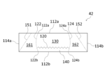
- FIG. 4 is a plan view showing a second embodiment of an item storage box according to the present invention.
- FIG. 2 is a plan view showing the holding portion 130.
- FIG. 2 is a plan view showing the holding portion 140.
- 2 is a perspective view showing the item storage box 2 when in use.
- FIG. 13 is a diagram for explaining the structure of the end face taken along line AA in FIG. 12. 13 is a plan view for explaining a modified example of the holding portion 130.
- FIG. 10A and 10B are diagrams for explaining the effects of the item storage box 2 according to the modified example.
- 13 is a plan view for explaining another modified example of the holding portion 130.
- FIG. 13 is a plan view for explaining another modified example of the holding portion 130.
- FIG. 13 is a plan view illustrating a modified example of the perforation 120.
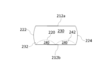
- FIG. 11 is a plan view showing a third embodiment of an item storage box according to the present invention.
- FIG. 2 is a plan view showing the holding portion 230.
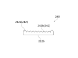
- FIG. 2 is a plan view showing a holding portion 240.
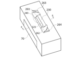
- 2 is a perspective view showing the item storage box 3 when in use.
- FIG. FIG. 24 is a diagram for explaining the structure of the end face taken along line BB in FIG. 23.
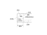
- 11A and 11B are diagrams for explaining the effect of the item storage box 3.
- 11A and 11B are diagrams for explaining the effect of the item storage box 3.
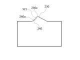
- 13 is a plan view for explaining a modified example of the holding portion 240.
- FIGS. 10A and 10B are diagrams for explaining the effects of the item storage box 3 according to the modified example.
- 13 is a plan view illustrating another modified example of the perforation 220.
- FIG. 13 is a plan view illustrating another modified example of the perforation 220.
- FIG. 13 is a plan view illustrating another modified example of the perforation 220.
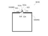
- FIG. 10 is an end view showing a fourth embodiment of an item storage box according to the present invention.
- FIG. 4 is a plan view showing the outer member 310.
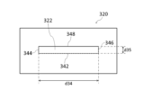
- FIG. 4 is a plan view showing the inner member 320.
- FIG. 1 is an end view showing a state in which tissue paper 90 is pulled out from the item storage box 4.
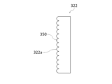
- FIG. 13 is a plan view showing a bent portion 322 according to a modified example.
- FIG. 13 is a plan view showing a bent portion 322 according to another modified example.
- FIG. 13 is a plan view showing a bent portion 322 according to another modified example.
- FIG. 13 is a plan view showing a bent portion 322 according to another modified example.
- 42 is a plan view for explaining the function of a recess 360 in FIG. 41.
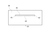
- FIG. 13 is a side view illustrating a modified example of the cut line 60.
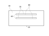
- 13 is a side view for explaining a modified example of the slit portion 80.
- FIG. 13 is a side view illustrating a modified example of the fold line 33.
- FIG. 13 is a side view for explaining another modified example of the cut line 60.
- FIG. 13 is a side view for explaining another modified example of the cut line 60.
- FIG. 13 is a side view for explaining another modified example of the cut line 60.
- FIG. 13 is a side view for explaining another modified example of the cut line 60.
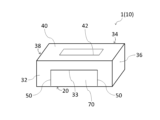
- FIGS. 1 and 2 are perspective views showing a first embodiment of an item storage box according to the present invention.
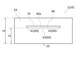
- FIG. 3 is a side view showing a first embodiment of an item storage box according to the present invention.
- the item storage box 1 is an item storage box in which a plurality of items are stored in a stacked state, and has a main body 10. Examples of items include tissue paper, paper towels, kitchen paper, gloves, or masks. In this embodiment, the item is tissue paper.
- the main body 10 is box-shaped and is made up of a bottom portion 20, a side portion 32 (first side portion), a side portion 34 (second side portion), a side portion 36 (third side portion), a side portion 38 (fourth side portion), and a top portion 40.
- the main body 10 is rectangular parallelepiped-shaped.
- Figures 1 and 2 are perspective views seen from the top portion 40 side and the bottom portion 20 side, respectively.
- Figure 3 is a side view seen from the side portion 34 side.
- the side portion 32 and the side portion 34 face each other.
- the side portion 36 and the side portion 38 also face each other.
- the widths of the side portions 32 and 34 are greater than the widths of the side portions 36 and 38.
- the main body 10 is configured so that it can be deformed into a bottom-up state.
- the material of the main body 10 can be, for example, paper such as cardboard, or plastic.
- the main body 10 has a cut line 50 (first cut line), a cut line 60 (second cut line), a tongue portion 70, and a slit portion 80.
- the cut line 50 is formed from the bottom portion 20 to the side portion 32.
- the cut line 50 is formed along a single continuous line.
- the cut line 50 is a perforation.
- the cut line 50 consists of a bottom cut portion 51 (first bottom cut portion), a bottom cut portion 52 (second bottom cut portion), a bottom cut portion 53 (third bottom cut portion), a side cut portion 54 (first side cut portion), and a side cut portion 55 (second side cut portion).
- the bottom cut portions 51 to 53 are formed in the bottom portion 20.
- the side cut portion 54 and the side cut portion 55 are formed in the side portion 32.
- the bottom cutout portion 51 and the bottom cutout portion 52, and the side cutout portion 54 and the side cutout portion 55 are all in a straight line.
- the bottom cutout portion 53 is also in a straight line.
- the bottom cut-out portion 51 and the bottom cut-out portion 52 extend from the side surface portion 32 toward the side surface portion 34.
- the bottom cut-out portion 51 and the bottom cut-out portion 52 extend perpendicular to the side surface portion 32.
- the bottom cut-out portion 53 connects the bottom cut-out portion 51 and the bottom cut-out portion 52.
- the bottom cut-out portion 53 connects one end of the bottom cut-out portion 51 and one end of the bottom cut-out portion 52.
- One end of the bottom cut-out portion 51 and one end of the bottom cut-out portion 52 are located in the middle of the bottom surface portion 20.
- the middle of the bottom surface portion 20 refers to the portion of the bottom surface portion 20 other than the edge (the boundary with each side surface portion 32, 34, 36, 38).
- the bottom cut-out portion 53 extends parallel to the side surface portion 32.
- the side cutout portion 54 and the side cutout portion 55 are continuous with the bottom cutout portion 51 and the bottom cutout portion 52, respectively. That is, one end of the side cutout portion 54 and one end of the side cutout portion 55 are connected to the other end of the bottom cutout portion 51 and the other end of the bottom cutout portion 52, respectively.
- the side cutout portion 54 and the side cutout portion 55 extend in the height direction of the main body 10 (the up-down direction in Figures 1 and 2).
- the other ends of the side cutout portion 54 and the side cutout portion 55 are located in the middle of the side portion 32.
- the middle portion of the side portion 32 refers to the part of the side portion 32 other than the edge (the boundary with the bottom portion 20, the boundaries with each side portion 36, 38, and the boundary with the top portion 40).
- the cut line 60 is formed on the side portion 34.
- the cut line 60 is formed along a single continuous line.
- the cut line 60 is a perforation.
- the cut line 60 includes a vertical cut portion 61 (first vertical cut portion), a vertical cut portion 62 (second vertical cut portion), and a horizontal cut portion 63.
- the cut line 60 consists only of the vertical cut portion 61, the vertical cut portion 62, and the horizontal cut portion 63.
- the vertical cut portion 61, the vertical cut portion 62, and the horizontal cut portion 63 are all straight.
- the vertical cut portion 61 and the vertical cut portion 62 extend in the height direction of the main body 10.
- the horizontal cut portion 63 connects one end of the vertical cut portion 61 and one end of the vertical cut portion 62.
- One end of the vertical cut portion 61 and one end of the vertical cut portion 62 are located in the middle of the side portion 34.
- the other end of the vertical cut portion 61 and the other end of the vertical cut portion 62 are also located in the middle of the side portion 34.
- the middle portion of the side portion 34 refers to the portion of the side portion 34 other than the edge (the boundary with the bottom portion 20, the boundaries with the side portions 36 and 38, and the boundary with the top portion 40).
- the horizontal cut portion 63 extends parallel to the bottom portion 20.
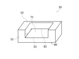
- Figures 4, 5, and 6 are respectively an oblique view, a plan view, and a side view showing the main body 10 after deformation.
- Figure 4 is an oblique view seen from the bottom surface portion 20 side.
- Figure 6 is a side view seen from the side surface portion 32 side.
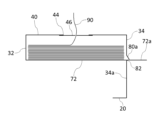
- Figure 7 is a diagram for explaining the structure of the end face along line VII-VII in Figure 5.
- the tongue portion 70 is a portion that becomes the tongue portion 72 connected to the middle portion of the side portion 32 when a cut is made in the main body 10 (bottom portion 20 and side portion 32) along the cut line 50.
- the tongue portion 72 is composed of a single plate consisting of a part of the bottom portion 20 and a part of the side portion 32. In this embodiment, the shape of the tongue portion 72 is rectangular.
- the side portion 32 is provided with a fold line 33 for folding the tongue portion 72 toward the side portion 34.
- the fold line 33 is provided at a position that overlaps with the slit portion 80 described later in a side view.
- the fold line 33 connects the other end of the side cut portion 54 and the other end of the side cut portion 55.
- the fold line 33 is parallel to the bottom portion 20. It is preferable that a fold line 33 is pre-formed in the fold line 33 so that the tongue portion 72 can be easily folded along the fold line 33.
- the fold line 33 may simply consist of a line printed on the side portion 32 to inform the user
- the length of the tongue 72 is preferably 1.1 times or more, more preferably 1.2 times or more, of the distance d0 (see FIG. 2) from the side portion 32 to the side portion 34.
- the length of the tongue 72 is preferably 1 cm or more larger than the distance d0, more preferably 2 cm or more larger.
- the length of the tongue 72 is the maximum dimension of the tongue 72 in the direction perpendicular to the side portion 32 when the tongue 72 is spread on a plane parallel to the bottom portion 20.
- the length of the tongue 72 is equal to the sum of the length d1 of each bottom cut portion 51, 52 and the length d2 of each side cut portion 54, 55.
- the width w1 of the tongue 72 is preferably 1/2 or more, more preferably 3/4 or more, of the width w0 of the side portion 32.
- the width w1 is the maximum dimension of the tongue 72 in the direction perpendicular to the side portion 36 and the side portion 38.
- the slit portion 80 is a portion that is located in the middle of the side portion 34 and that becomes a slit 82 into which the tongue piece 72 can be inserted when the main body 10 (side portion 34) is cut along the cut line 60.
- the slit 82 is a horizontally long opening that extends parallel to the bottom portion 20.
- the tongue piece 72 is configured to be parallel to the bottom portion 20 when inserted into the slit 82.
- the side portion 34 is provided with a fold line 35 for folding the portion 80a surrounded by the cut line 60 (the vertical cut portion 61, the vertical cut portion 62, and the horizontal cut portion 63) to the outside of the main body 10.
- the fold line 35 connects the other end of the vertical cut portion 61 and the other end of the vertical cut portion 62.
- the fold line 35 is parallel to the bottom portion 20. It is preferable that the fold line 35 has a fold line formed in advance so that the portion 80a can be easily folded along the fold line 35. However, the fold line 35 may simply consist of a line printed on the side portion 34 to inform the user of the fold position.
- the distance h1 (see FIG. 3) from the bottom surface portion 20 to the slit portion 80 is equal to or greater than 1/2 of the height h0 of the main body 10.
- the distance from the bottom surface portion 20 to the fold line 33 (equal to the length d2 of each side cut portion 54, 55) is equal to or greater than 1/2 of the height h0.
- the top surface portion 40 is provided with an outlet forming portion 42.
- the outlet forming portion 42 is the portion where an outlet for items is formed.
- the outlet forming portion 42 has perforations formed along a single circular line.
- An outlet is formed in the outlet forming portion 42 by cutting the top surface portion 40 along the perforations and cutting off the portion surrounded by the perforations.
- a plastic film 46 is provided at the outlet, as in a typical tissue storage box (see Figure 5). The plastic film 46 has cuts that allow items to pass through.
- the main body 10 is cut along the cut line 60.
- the part 80a surrounded by the cut line 60 is folded outward along the fold line 35 to turn the slit portion 80 into a slit 82.
- the tongue portion 70 is made into a tongue 72 by cutting the main body 10 along the cut line 50.
- the tongue 72 is inserted into the slit 82 while being folded toward the side portion 34 along the fold line 33. This allows the main body 10 to be deformed so that the tongue 72 is inserted into the slit 82 (see Figures 4 to 7).
- the tissue paper 90 is placed on the tongue 72 as shown in Figure 7.
- the tissue paper 90 By raising the bottom of the item storage box 1 (main body 10) in this way and bringing the tissue paper 90 closer to the upper surface portion 40, the tissue paper 90 can be smoothly taken out from the take-out opening 44 even when the amount of tissue paper 90 remaining is low. At this time, it is preferable that the distance from the tongue piece 72 to the upper surface portion 40 is 3 cm or more and 6 cm or less. Note that the tissue paper 90 is not shown in Figures 5 and 6.
- the protruding portion 72a of the tongue 72 is printed with letters or a design.
- the protruding portion 72a is the portion that protrudes from the slit 82 to the outside of the main body 10.
- the letters or design are printed on the top surface of the protruding portion 72a (the surface on the top surface portion 40 side).
- the character string "ABC” is printed on the top surface of the protruding portion 72a as an example.
- This top surface corresponds to a part of the inner surface of the bottom surface portion 20 of the main body 10 before deformation.
- the protruding portion 72a may be printed with a promotional message or advertising slogan for the company.
- the content of the company promotional message could be, for example, an introduction to the company's efforts in addressing environmental issues.
- the specific portion 34a is a portion that overlaps with the tongue portion 70 (the portion of the tongue portion 70 that is present on the side portion 32) in a side view.
- the character string "XYZ" is printed on the specific portion 34a as an example. However, in FIG. 4, the character string is not shown.
- An advertising slogan may be printed on the specific portion 34a.
- the scented section 12 may be provided in the lower part 10a of the inner surface of the main body 10, as shown in FIG. 8, for example.
- the lower part 10a is the part that exists below the tongue piece 72 when inserted into the slit 82.
- the lower part 10a is made up of a part of the inner surface of the bottom part 20 and a part of the inner surface of each of the side parts 32, 34, 36, and 38.
- the scented section 12 is provided in a specific part 34a that is a part of the lower part 10a.
- a fragrance is attached to the scented section 12.
- the scented section 12 can be realized, for example, by printing a fragrance on the lower part 10a.
- a peelable sticker 14 is attached to the scented section 12.
- peelable means that the sticker 14 can be easily peeled off from the scented section 12 without damaging the lower part 10a and the scented section 12.
- the sticker 14 prevents the fragrance of the scented section 12 from dissipating.
- the tongue portion 70 and the slit portion 80 are provided on the main body 10.
- the tongue portion 70 provides a tongue 72 connected to the middle portion of the side portion 32.
- the slit portion 80 provides a slit 82 that is located in the middle portion of the side portion 34 and into which the tongue 72 can be inserted.
- the tongue 72 can be stretched from the middle portion of the side portion 32 to the middle portion of the side portion 34. Therefore, when the remaining amount of items is low, the tongue 72 can be inserted into the slit 82 so that the item is placed on the tongue 72, and the bottom of the item storage box 1 can be raised while the tongue 72 is in surface contact with the item. Therefore, an item storage box 1 that can stably support items when the bottom is raised is realized without providing a bottom-raising member separate from the main body 10.
- an item storage box In an item storage box, storing as many items as possible is advantageous in terms of keeping the price per item down.
- the height of the main body In order to increase the number of items that can be stored in one item storage box, the height of the main body must be increased. Normally, when the height of the main body is increased, there is a problem that it becomes difficult to remove items when there are only a few items left. In this regard, with item storage box 1, which can be raised at the bottom, items can be easily removed even when there are only a few items left, so the above problem caused by increasing the height of main body 10 can be solved. Also, by increasing the height of main body 10, a large space can be secured for printing letters or patterns. Furthermore, since used main body 10 becomes garbage, storing a large number of items in one main body 10 also leads to a reduction in garbage.
- the tongue 72 is connected to the side portion 32 without being separated from the main body 10. In this case, a part of the tongue 72 is fixed to the side portion 32, so that the tongue 72 is less likely to accidentally come out of the slit 82.
- the tongue piece 72 is configured to be parallel to the bottom surface 20 when inserted into the slit 82. This also contributes to stable support of items in the item storage box 1 after the bottom is raised.
- Increasing the distance h1 from the bottom surface portion 20 to the slit portion 80 in the height direction of the main body 10 is advantageous in increasing the bottom-raising effect of the item storage box 1. From this perspective, it is preferable that the distance h1 is equal to or greater than 1/2 of the height h0 of the main body 10. On the other hand, if the distance h1 is too large, the amount of items that can be stored in the item storage box 1 after deformation will be extremely small. From this perspective, it is preferable that the distance h1 is equal to or less than 4/5 of the height h0.
- the side portion 32 has a fold line 33. This makes it easier to fold the tongue piece 72 neatly at the specified position.
- the fold line 33 is positioned so that it overlaps the slit portion 80 in a side view. This makes it easier to position the tongue piece 72 inserted into the slit 82 parallel to the bottom portion 20.
- the length of the tongue 72 is preferably 1.1 times or more, and more preferably 1.2 times or more, the distance d0 from the side portion 32 to the side portion 34. From a similar perspective, the length of the tongue 72 is preferably 1 cm or more longer than the distance d0, and more preferably 2 cm or more longer. On the other hand, if the length of the tongue 72 is too large, it may be difficult to secure the tongue portion 70 in the main body 10 before deformation. From this perspective, the length of the tongue 72 is preferably 1.5 times or less than the distance d0. From a similar perspective, the difference between the length of the tongue 72 and the distance d0 is preferably 5 cm or less.
- the cut line 50 is made up of bottom cut portions 51 to 53, as well as side cut portions 54 and 55. This allows the cut line 50 for forming the tongue piece 72 to be realized with a simple configuration.
- the bottom cut portions 51 and 52, and the side cut portions 54 and 55 are all in a straight line. This makes it easy to make cuts along the bottom cut portions 51, 52 and the side cut portions 54, 55.
- the bottom cutout portion 51 and the bottom cutout portion 52 extend perpendicular to the side portion 32. In this case, the length of each bottom cutout portion 51, 52 can be minimized. This also makes it easier to make cuts along each bottom cutout portion 51, 52.
- the side cut portions 54 and 55 extend in the height direction of the main body 10. In this case, the length of each side cut portion 54, 55 can be minimized. This also makes it easier to make cuts along each side cut portion 54, 55.
- the bottom cut portion 53 is in a straight line. This makes it easy to make cuts along the bottom cut portion 53.
- the bottom cutout portion 53 extends parallel to the side portion 32. This allows the dimensions of the tongue piece 72 in the direction perpendicular to the side portion 32 to be constant.
- the width w1 of the tongue 72 is advantageous for stably supporting items in the item storage box 1 after the bottom has been raised, since the tongue 72 will come into contact with a wider area of the item.
- the width w1 is preferably at least 1/2 the width w0 of the side portion 32, and more preferably at least 3/4.
- the width w1 is preferably at most 9/10 of the width w0.
- the width of side portion 32 and side portion 34 is greater than the width of side portion 36 and side portion 38.
- the cut line 60 includes a vertical cut portion 61, a vertical cut portion 62, and a horizontal cut portion 63. This allows the cut line 60 for forming the slit 82 to be realized with a simple configuration.
- the vertical cut portions 61 and 62, and the horizontal cut portion 63 are all in a straight line. This makes it easy to make cuts along the vertical cut portions 61 and 62, and the horizontal cut portion 63.
- the cut line 60 consists only of the vertical cut portion 61, the vertical cut portion 62, and the horizontal cut portion 63.
- the portion 80a surrounded by the cut line 60 is not cut off from the main body 10, so it is possible to abut the portion 80a against the protruding portion 72a of the tongue piece 72. This makes it even more difficult for the tongue piece 72 to accidentally slip out of the slit 82.
- Letter or a design is printed on the protruding portion 72a of the tongue piece 72.
- the letters or designs are printed on the top surface of the protruding portion 72a. By printing on the top surface, where they are easily visible, the letters or designs can be made to stand out.
- the outlet portion 72a can be used as advertising space. By recruiting advertisers, it is possible to earn advertising revenue. If this revenue is used to cover the manufacturing costs of the item storage box 1, the product price of the item storage box 1 can be reduced.
- Letter or a design is printed on the specific portion 34a on the inner surface of the side portion 34.
- the specific portion 34a can be used as advertising space. By recruiting advertisers, it is possible to earn advertising revenue. If this revenue is used to cover the manufacturing costs of the item storage box 1, the product price of the item storage box 1 can be reduced.
- the scented section 12 is provided on the lower portion 10a of the inner surface of the main body 10, it is possible to disperse a fragrance around the main body 10 after it has been deformed. In other words, by peeling off the seal 14 after the main body 10 has been deformed, the fragrance in the scented section 12 can be dispersed around the main body 10. In addition, because the seal 14 is affixed to the scented section 12, the user can choose whether or not to disperse a fragrance around the main body 10 by whether or not to peel off the seal 14.
- FIG. 9 is a plan view showing a second embodiment of an item storage box according to the present invention.
- the item storage box 2 is an item storage box in which multiple items are stored in a stacked state, and includes a main body 10.
- the configuration of the outlet forming section 42 differs from that of the first embodiment.
- the other configurations of the main body 10 are as described in the first embodiment.
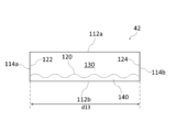
- the outlet forming section 42 is a rectangular area on the top surface 40 surrounded by the long side 112a (first long side) and the long side 112b (second long side) as well as the short side 114a (first short side) and the short side 114b (second short side).
- the outlet forming section 42 has a perforation 120 (first main cut line), a perforation 122 (second main cut line), and a perforation 124 (third main cut line).
- the perforation 120 is wavy and extends in the longitudinal direction of the outlet forming section 42 (left and right direction in FIG. 9).
- the perforation 120 is formed along a single continuous wavy line. In this embodiment, this wavy line consists of a broken line and a curved line. Specifically, the portions near both ends of the perforation 120 (one end 120a and the other end 120b) consist of curved lines, and the remaining portions consist of broken lines.
- Each curved line bulges toward the long side 112a. Both ends of each curved line are on the long side 112b. One end of each line segment that constitutes the broken line also exists on the long side 112b.
- the perforation 120 is symmetrical with respect to the center line that bisects the outlet forming section 42 in the longitudinal direction.
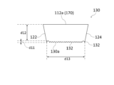
- the distance d11 (see FIG. 10 and FIG. 11 described later) from the apex 120c of the perforation 120 to the long side 112b is less than half the distance d12 (see FIG. 10) from the apex 120c to the long side 112a.
- the apex 120c is the part of the perforation 120 closest to the long side 112a.
- the tip of the convex portion 142a described later corresponds to the apex 120c.
- the distance d11 is preferably 0.1 or more and 0.3 or less.
- the distance d13 (see Figures 10 and 11) from one end 120a to the other end 120b of the perforation 120 is smaller than the length of the long side 112a (which is equal to the length of the long side 112b). It is preferable that the distance d13 is 40% or more and 60% or less of the length of the long side 112a.
- the perforation 122 intersects with one end 120a of the perforation 120 and connects the long side 112a and long side 112b of the outlet forming section 42.
- one end 120a of the perforation 120 is located on the long side 112b. Therefore, the perforation 122 intersects with one end 120a of the perforation 120 at the end 122b on the long side 112b side.
- the perforation 122 is straight.
- the perforation 122 is formed along a diagonal straight line. The distance from the end 122a of the perforation 122 on the long side 112a side to the short side 114a is smaller than the distance from the end 122b of the perforation 122 to the short side 114a.
- the perforation 124 intersects with the other end 120b of the perforation 120 and connects the long side 112a and long side 112b of the outlet forming section 42.
- the other end 120b of the perforation 120 is located on the long side 112b. Therefore, the perforation 124 intersects with the other end 120b of the perforation 120 at the end 124b on the long side 112b side.
- the perforation 124 is straight.
- the perforation 124 is formed along a diagonal straight line. The distance from the end 124a on the long side 112a side of the perforation 124 to the short side 114b is smaller than the distance from the end 124b of the perforation 124 to the short side 114b.
- FIGS. 10 and 11 are plan views showing holding portion 130 and holding portion 140, respectively.
- Holding portion 130 (first holding portion) is the portion surrounded by perforations 120, 122, 124 and long side 112a in removal opening forming portion 42.
- Holding portion 140 (second holding portion) is the portion surrounded by perforations 120, 122, 124 and long side 112b in removal opening forming portion 42 (including the portion surrounded only by perforation 120 and long side 112b).
- the opposing side 130a of the holding portion 130 has multiple protrusions 132.
- the opposing side 130a is the side of the holding portion 130 that faces the holding portion 140.
- the opposing side 130a coincides with the cut edge when the outlet forming portion 42 is cut along the perforation 120.
- the multiple protrusions 132 include angular protrusions that are protrusions with angular tips. In this embodiment, all of the protrusions 132 on the opposing side 130a are angular protrusions.
- Each of the protrusions 132 on the opposing side 130a reaches the long side 112b.
- the opposing side 140a of the holding portion 140 has a plurality of convex portions 142.
- the opposing side 140a is the side of the holding portion 140 that faces the holding portion 130.
- the opposing side 140a coincides with the cut edge when the outlet forming portion 42 is cut along the perforation 120.
- the plurality of convex portions 142 include round convex portions that are convex portions with rounded tips, in addition to angular convex portions. In the short direction of the outlet forming portion 42, the convex portion 142a located at the extreme end of the opposing side 140a protrudes more than the convex portion 142b located at a position other than the extreme end of the opposing side 140a.
- the tip of the convex portion 142a is closer to the long side 112a than the tip of the convex portion 142b.
- the convex portion 142a is a round convex portion
- the convex portion 142b is an angular convex portion.
- the long side 112a is provided with a fold line 170 (valley fold line) for folding the holding portion 130 along the long side 112a.
- the fold line 170 is provided on a line segment connecting the end 122a of the perforation 122 and the end 124a of the perforation 124. It is preferable that the fold line 170 has a crease formed in advance so that the holding portion 130 can be easily folded along the fold line 170.
- the fold line 170 may consist only of a line printed on the top surface portion 40 to inform the user of the fold position.
- the long side 112b does not have a fold line for folding the holding portion 140 along the long side 112b. That is, in this embodiment, the item storage box 2 is used in a state in which the holding portion 140 is not folded.
- the outlet forming section 42 has a perforation 151 (first minor cut line), a perforation 152 (second minor cut line), a perforation 153 (third minor cut line), and a perforation 154 (fourth minor cut line).
- the perforation 151 connects the end 122a of the perforation 122 to the long side 112b.
- the perforation 151 is straight.
- the perforation 151 is formed along a diagonal straight line.
- the distance from the end 151a of the perforation 151 on the long side 112a side to the short side 114a is greater than the distance from the end 151b of the perforation 151 on the long side 112b side to the short side 114a.
- the auxiliary section 161 (first auxiliary section), which is the section surrounded by the perforation 122, the perforation 151, and the long side 112b, is triangular.
- the perforation 152 connects the end 124a of the perforation 124 to the long side 112b.
- the perforation 152 is straight.
- the perforation 152 is formed along a diagonal straight line.
- the distance from the end 152a on the long side 112a side of the perforation 152 to the short side 114b is greater than the distance from the end 152b on the long side 112b side of the perforation 152 to the short side 114b.
- the auxiliary portion 162 (second auxiliary portion), which is the portion surrounded by the perforation 124, the perforation 152, and the long side 112b, is triangular.
- the long side 112b is provided with a fold line 171 (valley fold line) for folding the auxiliary portion 161 along the long side 112b.
- the fold line 171 is provided on a line segment connecting the end 122b of the perforation 122 and the end 151b of the perforation 151. It is preferable that the fold line 171 has a crease formed in advance so that the auxiliary portion 161 can be easily folded along the fold line 171.
- the long side 112b is provided with a fold line 172 (valley fold line) for folding the auxiliary portion 162 along the long side 112b.
- the fold line 172 is provided on a line segment connecting the end 124b of the perforation 124 and the end 152b of the perforation 152. It is preferable that the fold line 172 has a crease formed in advance so that the auxiliary portion 162 can be easily folded along the fold line 172.
- the perforation 153 connects the end 151b of the perforation 151 to the long side 112a.
- the perforation 153 is straight.
- the perforation 153 is formed along a diagonal straight line.
- the distance from the end 153a of the perforation 153 on the long side 112a side to the short side 114a is smaller than the distance from the end 153b of the perforation 153 on the long side 112b side to the short side 114a.
- the end 153a is located on the short side 114a. Therefore, the distance from the end 153a to the short side 114a is 0.
- the auxiliary portion 163 (third auxiliary portion), which is the portion surrounded by the perforation 151, the perforation 153, and the long side 112a, is triangular.
- the perforation 154 connects the end 152b of the perforation 152 to the long side 112a.
- the perforation 154 is straight.
- the perforation 154 is formed along a diagonal straight line.
- the distance from the end 154a of the perforation 154 on the long side 112a side to the short side 114b is smaller than the distance from the end 154b of the perforation 154 on the long side 112b side to the short side 114b.
- the end 154a is located on the short side 114b. Therefore, the distance from the end 154a to the short side 114b is 0.
- the auxiliary portion 164 (fourth auxiliary portion), which is the portion surrounded by the perforation 152, the perforation 154, and the long side 112a, is triangular.
- the long side 112a is provided with a fold line 173 (valley fold line) for folding the auxiliary portion 163 along the long side 112a.
- the fold line 173 is provided on a line segment connecting the end 151a of the perforation 151 and the end 153a of the perforation 153. It is preferable that the fold line 173 has a crease formed in advance so that the auxiliary portion 163 can be easily folded along the fold line 173.
- the long side 112a is provided with a fold line 174 (valley fold line) for folding the auxiliary portion 164 along the long side 112a.
- the fold line 174 is provided on a line segment connecting the end 152a of the perforation 152 and the end 154a of the perforation 154. It is preferable that the fold line 174 has a crease formed in advance so that the auxiliary portion 164 can be easily folded along the fold line 174.
- Perforations 155 are formed on the short side 114a.
- the perforations 155 are provided along the entire short side 114a.
- the auxiliary portion 165 which is the portion surrounded by the perforations 153, 155, and the long side 112b, has a right-angled triangle shape.
- a perforation 156 (cut line) is formed on the short side 114b.
- the perforation 156 is provided along the entire short side 114b.
- the auxiliary portion 166 which is the portion surrounded by the perforation 154, the perforation 156, and the long side 112b, has a right-angled triangle shape.
- the long side 112b is provided with a fold line 175 (valley fold line) for folding the auxiliary portion 165 along the long side 112b.
- the fold line 175 is provided on a line segment connecting the end 153b of the perforation 153 and the end of the perforation 155 on the long side 112b side. It is preferable that the fold line 175 has a crease formed in advance so that the auxiliary portion 165 can be easily folded along the fold line 175.
- the long side 112b is provided with a fold line 176 (valley fold line) for folding the auxiliary portion 166 along the long side 112b.
- the fold line 176 is provided on a line segment connecting the end 154b of the perforation 154 and the end of the perforation 156 on the long side 112b side. It is preferable that the fold line 176 has a crease formed in advance so that the auxiliary portion 166 can be easily folded along the fold line 176.
- FIG. 12 is a perspective view showing the item storage box 2 when in use.
- FIG. 13 is a view for explaining the structure of the end surface along line A-A in FIG. 12. Items are not shown in FIGS. 12 and 13.
- To use the item storage box 2 first, cuts are made in the outlet forming section 42 along the perforations 120, 122, and 124. Then, the holding section 130 is folded diagonally upward along the fold line 170. This forms a gap S11, which serves as an outlet, between the holding section 130 and the holding section 140. Furthermore, in this embodiment, cuts are made in the outlet forming section 42 along the perforations 151-156. Then, the auxiliary sections 161-166 are folded diagonally upward along the fold lines 171-176, respectively. This results in the item storage box 2 shown in FIG. 12.
- the item storage box 2 has perforations 120, 122, and 124.
- the outlet forming section 42 has a holding section 130, which is a section surrounded by the perforations 120, 122, and 124 and the long side 112a, and a holding section 140, which is a section surrounded by the perforations 120, 122, and 124 and the long side 112b.
- the holding section 130 can be folded diagonally upward to form a gap S11, which serves as an outlet, between the holding section 130 and the holding section 140.
- the perforation 120 is wavy, unevenness is generated on the opposing sides 130a and 140a of the holding sections 130 and 140.
- the holding force of the holding sections 130 and 140 for holding items can be strengthened.
- the distance d11 from the top 120c of the perforation 120 to the long side 112b is less than half the distance d12 from the top 120c to the long side 112a.
- an item storage box 2 is realized that can simultaneously strengthen the holding force for the item and facilitate the removal of the item.
- the distance d11 in the short direction of the outlet forming section 42 be 0.3 or less.
- the distance d11 be 0.1 or more.
- the opposing side 130a of the holding portion 130 has multiple protrusions 132. This allows the holding force of the holding portion 130 on the item to be strengthened compared to when there is only one protrusion 132.
- the multiple protrusions 132 include angular protrusions.
- the holding force of the holding portion 130 can be strengthened compared to when all of the protrusions 132 are round protrusions.
- Each of the protrusions 132 on the opposing side 130a reaches the long side 112b. In this way, moving the perforations 120 as close as possible to the long side 112b is particularly advantageous for ensuring a wide gap S11 in the height direction of the main body 10.
- the opposing side 140a of the holding portion 140 has multiple protrusions 142. This allows the holding force of the holding portion 140 on the item to be strengthened compared to when there is only one protrusion 142.
- the multiple protrusions 142 include angular protrusions.
- the holding force of the holding portion 140 can be strengthened compared to when all of the protrusions 142 are round protrusions.
- the multiple protrusions 142 include rounded protrusions. In this case, compared to when all of the protrusions 142 are angular protrusions, the item is less likely to get caught on the protrusions 142 when being removed, making it easier to remove the item smoothly.
- the protrusion 142a located at the very end of the opposing side 140a protrudes more than the protrusions 142b located other than at the very end. By making the rounded protrusion 142a protrude, it becomes less likely that an item will get caught on the angular protrusion 142b when it is taken out. This also reduces the risk of a user (especially a child) getting injured by touching the angular protrusion 142b.
- the long side 112a has a fold line 170. This makes it easier to fold the holding portion 130 at a predetermined position (fold line 170).
- the distance d13 from one end 120a to the other end 120b of the perforation 120 is smaller than the length of the long side 112a. This allows the width of the outlet to be smaller than the width of the outlet forming section 42 (the length of the long side 112a). If the width of the outlet is made smaller in this way, the item pulled out from the outlet is more likely to wrinkle. If this happens, the item will spread in the short direction of the outlet forming section 42, making it easier for both the opposing side 130a of the holding section 130 and the opposing side 140a of the holding section 140 to come into contact with the item. This is therefore advantageous in strengthening the holding force of the holding section 130 and the holding section 140.
- the distance d13 is 60% or less of the length of the long side 112a.
- the distance d13 is 40% or more of the length of the long side 112a.
- the outlet forming section 42 has perforations 151 and 152. This allows the auxiliary sections 161 and 162 to be folded diagonally upward. These auxiliary sections 161 and 162 can restrict the items pulled out from the outlet from spreading out on either side of the outlet.
- the long side 112b has fold lines 171 and 172. This makes it easier to fold the auxiliary parts 161 and 162 at the specified positions (fold lines 171 and 172, respectively).
- the outlet forming section 42 has perforations 153 and 154. This allows the auxiliary sections 163 and 164 to be folded diagonally upward. These auxiliary sections 163 and 164 can restrict the items pulled out from the outlet from spreading out on either side of the outlet.
- the long side 112a has fold lines 173 and 174. This makes it easier to fold the auxiliary parts 163 and 164 at the predetermined positions (fold lines 173 and 174, respectively).
- Other effects of the item storage box 2 are the same as those of the item storage box 1.
- the multiple convex portions 132 on the opposing side 130a may include round convex portions.
- all of the convex portions 132 may be round convex portions, or some of the convex portions 132 may be round convex portions and the remaining convex portions 132 may be angular convex portions.
- the tips of all of the protrusions 132 on the opposing side 130a are aligned.
- the protrusion 132 located at the very end of the opposing side 130a may protrude further than the protrusions 132 located other than at the very end (protrusion 132b) in the short direction of the outlet forming section 42.
- protrusions 142a some of the multiple protrusions 142 on the opposing side 140a of the holding portion 140 (protrusions 142a) are rounded and the remaining protrusions (protrusions 142b) are angular.
- all of the protrusions 142 on the opposing side 140a may be rounded, or all of the protrusions 142 on the opposing side 140a may be angular.
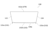
- FIG. 15 shows the same end face as FIG. 13.
- each of the protrusions 132 on the opposing side 130a of the holding portion 130 reaches the long side 112b.
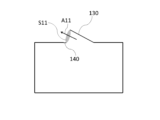
- only some of the multiple protrusions 132 on the opposing side 130a may reach the long side 112b, or as shown in FIG. 17, all of the protrusions 132 may be spaced apart from the long side 112b.
- the distance d13 from one end 120a to the other end 120b of the perforation 120 is smaller than the length of the long side 112a.
- the distance d13 may be equal to the length of the long side 112a.
- the perforation 120 may be formed over the entire longitudinal direction of the outlet forming section 42.
- the perforations 151-156, the auxiliary sections 161-166, and the fold lines 171-176 are not provided.
- the perforations 122 and 124 are formed on the short sides 114a and 114b, respectively.
- the perforations 122 and 124 are shown as straight lines. However, as shown in FIG. 19, the perforations 122 may be curved toward the perforations 151. Similarly, the perforations 124 may be curved toward the perforations 152. In FIG. 19, the distance from the end 122a of the perforations 122 to the short side 114a is equal to the distance from the end 122b of the perforations 122 to the short side 114a. Also, the distance from the end 124a of the perforations 124 to the short side 114b is equal to the distance from the end 124b of the perforations 124 to the short side 114b.
- FIG. 20 is a plan view showing a third embodiment of an item storage box according to the present invention.
- the item storage box 3 is an item storage box in which a plurality of items are stored in a stacked state, and includes a main body 10.
- the configuration of the outlet forming section 42 differs from that of the first and second embodiments.
- the other configuration of the main body 10 is as described in the first embodiment.
- the outlet forming section 42 is a rectangular area on the top surface 40 surrounded by the long side 212a (first long side) and the long side 212b (second long side) as well as the short side 214a (first short side) and the short side 214b (second short side).
- the outlet forming section 42 has a perforation 220 (first main cut line), a perforation 222 (second main cut line), and a perforation 224 (third main cut line).
- the perforation 220 extends in the longitudinal direction of the outlet forming section 42 (left and right direction in FIG. 20).
- the perforation 220 is wavy and is formed along a single continuous wavy line. This wavy line is made up of straight lines and curved lines. Specifically, the portions near both ends of the perforation 220 (ends 220a and 220b) are made up of straight lines, and the remaining portions are made up of curved lines. Each curved line bulges toward the long side 212a.
- the perforation 220 is symmetrical with respect to a center line that bisects the outlet forming section 42 in the longitudinal direction.
- the distance d21 from the apex 220c of the perforation 220 to the long side 212b is less than half the distance d22 from the apex 220c to the long side 212a (see FIG. 21).
- the apex 220c is the part of the perforation 220 closest to the long side 212a.
- the tip of the convex portion 242 described later corresponds to the apex 220c.
- the distance d21 is preferably 0.1 or more and 0.3 or less.
- the distance d23 (see Figures 21 and 22) from the end 220a to the end 220b of the perforation 220 is smaller than the length of the long side 212a (which is equal to the length of the long side 212b). It is preferable that the distance d23 is 40% or more and 60% or less of the length of the long side 22a.
- the perforation 222 intersects with the end 220a (first end) of the perforation 220 on the short side 214a side, and connects the long sides 212a and 212b of the outlet forming section 42.
- the end 222a (first end) of the perforation 222 on the long side 212a side is located on the long side 212a.
- the end 222b (second end) of the perforation 222 on the long side 212b side is located on the long side 212b.
- the end 220a of the perforation 220 is located on the long side 212b. Therefore, the perforation 222 intersects with the end 220a of the perforation 220 at its end 222b.
- the perforation 222 is curved and bulges toward the short side 214a. It is preferable that the perforation 222 is arc-shaped.
- the outermost portion 222c which is the portion of the perforation 222 closest to the short side 214a, is between the end 220a of the perforation 220 and the long side 212a. Therefore, the outermost portion 222c does not coincide with the end 220a and is not present on the long side 212a.
- the distance from the end 222a of the perforation 222 to the short side 214a is equal to or greater than the distance from the end 222b of the perforation 222 to the short side 214a. In other words, the former distance may be equal to or greater than the latter distance.
- the perforation 224 intersects with the end 220b (second end) on the short side 214b side of the perforation 220, and connects the long sides 212a and 212b of the outlet forming section 42.
- the end 224a (first end) on the long side 212a side of the perforation 224 is located on the long side 212a.
- the end 224b (second end) on the long side 212b side of the perforation 224 is located on the long side 212b.
- the end 220b of the perforation 220 is located on the long side 212b. Therefore, the perforation 224 intersects with the end 220b of the perforation 220 at its end 224b.
- the perforation 224 is curved and bulges toward the short side 214b. It is preferable that the perforation 224 is arc-shaped.
- the outermost portion 224c which is the portion of the perforation 224 closest to the short side 214b, is between the end 220b of the perforation 220 and the long side 212a. Therefore, the outermost portion 224c does not coincide with the end 220b and is not present on the long side 212a.
- the distance from the end 224a of the perforation 224 to the short side 214b is equal to or greater than the distance from the end 224b of the perforation 224 to the short side 214b. In other words, the former distance may be equal to or greater than the latter distance.
- the holding portion 230 (first holding portion) is the portion surrounded by the perforations 220, 222, 224 and the long side 212a in the outlet forming portion 42.
- the holding portion 240 (second holding portion) is the portion surrounded by the perforations 220, 222, 224 and the long side 212b in the outlet forming portion 42 (including the portion surrounded only by the perforations 220 and the long side 212b).
- the opposing side 230a of the holding portion 230 has a plurality of protrusions 232.
- the opposing side 230a is the side of the holding portion 230 that faces the holding portion 240.
- the opposing side 230a coincides with the cut edge when the outlet forming portion 42 is cut along the perforation 220.
- the plurality of protrusions 232 include angular protrusions that are protrusions with angular tips. In this embodiment, all of the protrusions 232 on the opposing side 230a are angular protrusions.
- the protrusion 232a located at the extreme end of the opposing side 230a protrudes more than the protrusions 232b located other than at the extreme end of the opposing side 230a.
- the tip of the protrusion 232a is closer to the long side 212b than the tip of the protrusion 232b.
- the protrusion 232a reaches the long side 212b.
- the opposing side 240a of the holding portion 240 has multiple protrusions 242.
- the opposing side 240a is the side of the holding portion 240 that faces the holding portion 230.
- the opposing side 240a coincides with the cut edge when the outlet forming portion 42 is cut along the perforation 220.
- the multiple protrusions 242 include rounded protrusions that are protrusions with rounded tips. In this embodiment, all of the protrusions 242 on the opposing side 240a are rounded protrusions.
- the long side 212a is provided with a fold line 270 (valley fold line) for folding the holding portion 230 along the long side 212a.
- the fold line 270 is provided on a line segment connecting the end 222a of the perforation 222 and the end 224a of the perforation 224. It is preferable that the fold line 270 has a crease formed in advance so that the holding portion 230 can be easily folded along the fold line 270.
- the fold line 270 may consist only of a line printed on the top surface portion 40 to inform the user of the fold position.
- the long side 212b does not have a fold line for folding the holding portion 240 along the long side 212b. That is, in this embodiment, the item storage box 3 is used in a state in which the holding portion 240 is not folded.
- the outlet forming section 42 has a perforation 251 (first minor cut line) and a perforation 252 (second minor cut line).
- the perforation 251 connects the end 222a of the perforation 222 to the long side 212b.
- the perforation 251 consists of a first and a second part.
- the first part of the perforation 251 is a linear part that extends along the long side 212a from the end 251a on the long side 212a side of the perforation 251 to the middle part 251c of the perforation 251.
- the middle part 251c is located on the long side 212a.
- the distance from the middle part 251c to the short side 214a is smaller than the distance from the end 251a to the short side 214a.
- the second portion of the perforation 251 is a curved portion extending from the middle portion 251c to the end portion 251b on the long side 212b side of the perforation 251.
- the second portion may be straight.
- the distance from the end portion 251b to the short side 214a is smaller than the distance from the middle portion 251c to the short side 214a.
- the end portion 251b is located on the short side 214a. Therefore, the distance from the end portion 251b to the short side 214a is 0.
- the long side 212b is provided with a fold line 271 (valley fold line) for folding the auxiliary part 261 (first auxiliary part), which is the part surrounded by the perforation 222, the perforation 251, and the long side 212b, along the long side 212b.
- the fold line 271 is provided on a line segment connecting the end 222b of the perforation 222 and the end 251b of the perforation 251. It is preferable that the fold line 271 has a crease formed in advance so that the auxiliary part 261 can be easily folded along the fold line 271.
- the perforation 252 connects the end 224a of the perforation 224 to the long side 212b.
- the perforation 252 consists of a first and a second part.
- the first part of the perforation 252 is a straight part that extends along the long side 212a from the end 252a on the long side 212a side of the perforation 252 to the middle part 252c of the perforation 252.
- the middle part 252c is located on the long side 212a.
- the distance from the middle part 252c to the short side 214b is smaller than the distance from the end 252a to the short side 214b.
- the second portion of the perforation 252 is a curved portion extending from the middle portion 252c to the end portion 252b on the long side 212b side of the perforation 252.
- the second portion may be straight.
- the distance from the end portion 252b to the short side 214b is smaller than the distance from the middle portion 252c to the short side 214b.
- the end portion 252b is located on the short side 214b. Therefore, the distance from the end portion 252b to the short side 214b is zero.
- the long side 212b is provided with a fold line 272 (valley fold line) for folding the auxiliary part 262 (second auxiliary part), which is the part surrounded by the perforation 224, the perforation 252, and the long side 212b, along the long side 212b.
- the fold line 272 is provided on a line segment connecting the end 224b of the perforation 224 and the end 252b of the perforation 252. It is preferable that the fold line 272 has a crease formed in advance so that the auxiliary part 262 can be easily folded along the fold line 272.
- a perforation 253 (cut line) is formed on the short side 214a.
- the perforation 253 is provided over the entire short side 214a.
- the long side 212a is provided with a fold line 273 (valley fold line) for folding the auxiliary portion 263, which is the portion surrounded by the perforation 251, the perforation 253, and the long side 212a, along the long side 212a.
- the fold line 273 is provided on a line segment connecting the middle portion 251c of the perforation 251 and the end of the perforation 253 on the long side 212a side. It is preferable that a crease is formed in advance on the fold line 273 so that the auxiliary portion 263 can be easily folded along the fold line 273.
- a perforation 254 (cut line) is formed on the short side 214b.
- the perforation 254 is provided over the entire short side 214b.
- the long side 212a is provided with a fold line 274 (valley fold line) for folding the auxiliary part 264, which is the part surrounded by the perforation 252, the perforation 254, and the long side 212a, along the long side 212a.
- the fold line 274 is provided on a line segment connecting the middle part 252c of the perforation 252 and the end part of the perforation 254 on the long side 212a side. It is preferable that a crease is formed in advance on the fold line 274 so that the auxiliary part 264 can be easily folded along the fold line 274.
- Figure 23 is a perspective view showing the state of the item storage box 3 when it is in use.
- Figure 24 is a diagram for explaining the structure of the end surface along the line B-B in Figure 23. In Figures 23 and 24, the illustration of items is omitted.
- the auxiliary sections 261 and 262 are folded diagonally upward along the fold lines 271 and 272, respectively.
- the holding section 230 is folded diagonally upward along the fold line 270.
- a gap S21 that serves as an outlet is formed between the holding section 230 and the holding section 240.
- the item storage box 3 is provided with perforations 220, 222, 224, and 251.
- the outlet forming section 42 has a holding section 230, which is the section surrounded by the perforations 220, 222, 224 and the long side 212a, a holding section 240, which is the section surrounded by the perforations 220, 222, 224 and the long side 212b, and an auxiliary section 261, which is the section surrounded by the perforations 222, 251, and the long side 212b.
- the auxiliary section 261 With cuts made along the perforations 220, 222, 224, and 251, the auxiliary section 261 is bent diagonally upward, and then the holding section 230 is bent diagonally upward, whereby a gap S21 serving as an outlet can be formed between the holding section 230 and the holding section 240.
- the auxiliary portion 261 interferes with the holding portion 230 when the holding portion 230 is folded upward. This prevents the folding angle of the holding portion 230 from becoming too large. This results in an item storage box 3 that can prevent a decrease in the holding force for holding items.
- auxiliary portion 261 restricts the movement of holding portion 230.
- the portion of holding portion 230 that coincides with outermost portion 222c of perforation 222 is portion 230c
- portion auxiliary portion 261 that coincides with outermost portion 222c of perforation 222 is portion 261c.
- portions 230c and 261c coincide.
- the distance from portion 230c (portion 261c) to short side 214a is distance d24.
- the portion 230c of the holding portion 230 moves toward the long side 212a
- the portion 261c of the auxiliary portion 261 moves toward the long side 212b.
- the portion of the opposing side of the auxiliary portion 261 (the side opposing the holding portion 230) where the distance to the long side 212a is equal to the distance from the portion 230c to the long side 212a is defined as the portion 261d.
- the distance from the portion 261d of the auxiliary portion 261 to the short side 214a is greater than the distance d24.
- a portion of the auxiliary portion 261 overlaps the holding portion 230.
- the outermost portion 222c of the perforation 222 is between the end portion 220a and the long side 212a of the perforation 220. This makes it easier to appropriately adjust the bending angle of the holding portion 230 compared to when the outermost portion 222c is on the end portion 220a or the long side 212a.
- the distance from end 222a of perforation 222 to short side 214a is equal to or greater than the distance from end 222b of perforation 222 to short side 214a.
- the change in distance from perforation 222 to short side 214a becomes steeper in the section between outermost portion 222c and end 222a. This makes it easier for auxiliary portion 261 to interfere with holding portion 230. For this reason, this configuration is suitable for cases where it is desired to maintain the bending angle of holding portion 230 relatively small.
- the curvature of the perforations 222 is constant, making it easier to form the perforations 222 and the cuts. This also contributes to improving the aesthetic appearance of the removal opening forming portion 42 and thus the item storage box 3.
- the long side 212a has a fold line 270. This makes it easier to fold the holding portion 230 at a predetermined position (fold line 270).
- the long side 212b has a fold line 271. This makes it easier to fold the auxiliary part 261 at a predetermined position (fold line 271).
- the outlet forming section 42 has an auxiliary section 262, which is a section surrounded by the perforation 224, the perforation 252, and the long side 212b.
- the perforation 224 is curved toward the short side 214b, when the holding section 230 is folded upward, not only the auxiliary section 261 but also the auxiliary section 262 interferes with the holding section 230.
- the auxiliary section 261 and the auxiliary section 262 interfere with both sides of the holding section 230, so that the bending angle of the holding section 230 can be more reliably prevented from becoming too large.
- these auxiliary sections 261 and 262 can also prevent the article pulled out from the outlet from spreading to both sides of the outlet. However, it is not essential to provide the perforation 252 and the auxiliary section 262.
- the outermost portion 224c of the perforation 224 is between the end portion 220b and the long side 212a of the perforation 220. This makes it easier to appropriately adjust the bending angle of the holding portion 230 compared to when the outermost portion 224c is on the end portion 220b or the long side 212a.
- the distance from the end 224a of the perforation 224 to the short side 214b is equal to or greater than the distance from the end 224b of the perforation 224 to the short side 214b.
- the change in the distance from the perforation 224 to the short side 214b becomes steeper in the section between the outermost portion 224c and the end 224a. This makes it easier for the auxiliary portion 262 to interfere with the holding portion 230. For this reason, this configuration is suitable when it is desired to maintain the bending angle of the holding portion 230 relatively small.
- the curvature of the perforations 224 is constant, making it easier to form the perforations 224 and the cuts. This also contributes to improving the aesthetic appearance of the removal opening forming portion 42 and thus the item storage box 3.
- the long side 212b has a fold line 272. This makes it easier to fold the auxiliary part 262 at a predetermined position (fold line 272).
- the perforations 220 are wavy. This creates unevenness on the opposing edges 230a, 240a of the holding parts 230, 240. This strengthens the holding power of the holding parts 230, 240 against the item.
- the distance d21 from the top 220c of the perforation 220 to the long side 212b is less than half the distance d22 from the top 220c to the long side 212a.
- the gap S21 between the holding parts 230 and 240 after folding is wide in the height direction of the main body 10 (the up and down direction in the figure). If the gap S21 is wide in the height direction, the object can be smoothly removed through the gap S21 by pulling up the object diagonally as shown by the arrow A21 in the figure.
- the distance d21 in the short direction of the outlet forming section 42 be 0.3 or less.
- the distance d21 be 0.1 or more.
- the opposing side 230a of the holding portion 230 has multiple protrusions 232. This allows the holding force of the holding portion 230 on the item to be strengthened compared to when there is only one protrusion 232.
- the multiple protrusions 232 include angular protrusions.
- the holding force of the holding portion 230 can be strengthened compared to when all of the protrusions 232 are round protrusions.
- the opposing side 240a of the holding portion 240 has multiple protrusions 242. This allows the holding force of the holding portion 240 on the item to be strengthened compared to when there is only one protrusion 242.
- the multiple protrusions 242 include rounded protrusions. In this case, compared to when all of the protrusions 242 are angular protrusions, the item is less likely to get caught on the protrusions 242 when being removed, making it easier to remove the item. In this embodiment, all of the protrusions 242 on the opposing side 240a are rounded protrusions, which is particularly advantageous in terms of ease of removing the item.
- the distance d23 from the end 220a to the end 220b of the perforation 220 is smaller than the length of the long side 212a. This allows the width of the outlet to be smaller than the width of the outlet forming section 42 (the length of the long side 212a). If the width of the outlet is made smaller in this way, the item pulled out from the outlet is more likely to wrinkle. If this happens, the item will spread in the short direction of the outlet forming section 42, making it easier for both the opposing side 230a of the holding section 230 and the opposing side 240a of the holding section 240 to come into contact with the item. This is therefore advantageous in strengthening the holding force of the holding section 230 and the holding section 240.
- the distance d23 is 60% or less of the length of the long side 212a.
- the distance d23 is 40% or more of the length of the long side 212a.
- the outlet forming section 42 has perforations 253 and 254. This allows the auxiliary sections 263 and 264 to be folded diagonally upward. These auxiliary sections 263 and 264 can prevent the item pulled out from the outlet from spreading out to both sides of the outlet. However, it is not essential to provide the perforations 253, 254 and the auxiliary sections 263, 264. Other effects of the item storage box 3 are the same as those of the item storage box 1.
- the multiple convex portions 232 on the opposing side 230a may include round convex portions.
- all of the convex portions 232 may be round convex portions, or some of the convex portions 232 may be round convex portions and the remaining convex portions 232 may be angular convex portions.
- the multiple convex portions 242 on the opposing side 240a may include angular convex portions.
- all of the convex portions 242 may be angular convex portions, or some of the convex portions 242 may be angular convex portions and the remaining convex portions 242 may be round convex portions.
- the protrusion 242 (protrusion 242a) located at the end of the opposing side 240a may protrude more than the protrusions 242 (protrusion 242b) located other than at the end.
- protrusion 242a which is a rounded protrusion
- protrusions make it less likely that an item will get caught on the protrusion 242b when it is taken out, if the protrusion 242b is an angular protrusion. This also reduces the risk of a user (especially a child) getting injured by touching the angular protrusion 242b.
- the long side 212b does not have a fold line for folding the holding portion 240 along the long side 212b is exemplified.
- a fold line may be provided on the long side 212b.
- the item storage box 3 is used with both the holding portion 230 and the holding portion 240 folded.
- the perforation 220 is closer to the long side 212b, as shown in FIG. 28, even if the holding portion 230 and the holding portion 240 are folded by the same angle, the opposing side 230a is located at a higher point than the opposing side 240a. Therefore, the gap S21 between the holding portion 230 and the holding portion 240 can be secured widely in the height direction of the main body 10.
- FIG. 28 shows the same end face as FIG. 24.
- the example shows a case where the distance from the end 222a of the perforation 222 to the short side 214a is equal to or greater than the distance from the end 222b to the short side 214a.
- the distance from the end 222a to the short side 214a may be smaller than the distance from the end 222b to the short side 214a.
- the change in the distance from the perforation 222 to the short side 214a becomes gentler in the section between the outermost portion 222c and the end 222a. This makes it less likely that the auxiliary portion 261 will interfere with the holding portion 230. For this reason, this configuration is suitable for cases where it is desired to maintain a relatively large bending angle of the holding portion 230.
- the example shows a case where the distance from the end 224a of the perforation 224 to the short side 214b is equal to or greater than the distance from the end 224b to the short side 214b.
- the distance from the end 224a to the short side 214b may be smaller than the distance from the end 224b to the short side 214b.
- the change in the distance from the perforation 224 to the short side 214b becomes gentler in the section between the outermost portion 224c and the end 224a. This makes it less likely that the auxiliary portion 262 will interfere with the holding portion 230. For this reason, this configuration is suitable for cases where it is desired to maintain a relatively large bending angle of the holding portion 230.
- the ends 220a and 220b of the perforation 220 are located on the long side 212b.
- the ends 220a and 220b may be located between the long sides 212a and 212b, as shown in FIG. 29.
- the perforation 220 is arranged closer to the long side 212b.
- the perforation 220 may be arranged so that it overlaps with the center line L21 that bisects the outlet forming portion 42 in the short direction.
- each of the opposing sides 230a, 240a has a large number (six or more) of protruding portions 232, 242.
- each of the opposing sides 230a, 240a may have a small number (fewer than six) of protruding portions 232, 242, as shown in FIG. 31.
- three protruding portions 232 and two protruding portions 242 are provided.
- the perforations 220 are wavy. However, the perforations 220 may be straight, as shown in FIG. 32.
- the end 251b of the perforation 251 is located on the short side 214a.
- the end 251b may be spaced apart from the short side 214a as shown in Fig. 33.
- the end 252b of the perforation 252 is also spaced apart from the short side 214b. In this case, the tip of each auxiliary portion 263, 264 can be prevented from becoming sharp.
- Figure 34 is an end view showing a fourth embodiment of an item storage box according to the present invention.
- the item storage box 4 is an item storage box in which a plurality of items are stored in a stacked state, and includes a main body 10.
- the configuration of the top surface portion 40 differs from the first to third embodiments.
- the rest of the configuration of the main body 10 is as described in the first embodiment.
- the upper surface portion 40 includes an outer member 310 and an inner member 320.
- the outer member 310 and the inner member 320 are each made of a single sheet of cardboard.
- the inner member 320 is provided so as to overlap the back surface of the outer member 310, and together with the outer member 310, constitutes the upper surface portion 40. In this way, the upper surface portion 40 has a double structure made up of the outer member 310 and the inner member 320.
- Figure 35 is a plan view showing the outer member 310.
- the outer member 310 has a bent portion 312 (first bent portion).
- the bent portion 312 is bent above the upper surface portion 40 to form an opening 314 (see Figure 34) in the outer member 310, which serves as an outlet.
- the bent portion 312 and the opening 314 are identical in shape and size. Note that Figure 35 shows the state before the bent portion 312 is bent.
- the bent portion 312 When the direction perpendicular to the side portions 36 and 38 is taken as the horizontal direction (left-right direction in FIG. 35), the bent portion 312 has a horizontally long shape. In this embodiment, the bent portion 312 has a rectangular shape. It is preferable that the horizontal length d31 of the bent portion 312 is 60% or more and 80% or less of the horizontal length d32 of the top surface portion 40. The vertical length d33 of the bent portion 312 (up-down direction in FIG. 35) is, for example, 7 mm or more and 15 mm or less.
- the outer member 310 has perforations 332, 334, and 336 formed as cut lines.
- the outer member 310 also has a fold line 338 (valley fold line).
- the portion surrounded by the perforations 332, 334, 336 and the fold line 338 is the folded portion 312.
- the perforations 332 and fold line 338 are formed along a straight line extending in the horizontal direction.
- the perforations 334 and 336 are formed along a straight line extending in the vertical direction.
- the perforation 334 connects one end of the perforation 332 to one end of the fold line 338.
- the perforation 336 connects the other end of the perforation 332 to the other end of the fold line 338.
- the folding portion 312 can be folded above the top surface portion 40 along the fold line 338. It is preferable that the fold line 338 has a crease formed in advance so that the folding portion 312 can be easily folded along the fold line 338.
- the fold line 338 may consist only of a line printed on the outer member 310 to inform the user of the position of the fold.
- FIG. 36 is a plan view showing the inner member 320.
- the inner member 320 has a bent portion 322 (second bent portion).
- the bent portion 322 is bent upward from the upper surface portion 40, thereby forming an opening 324 (second opening) in the inner member 320 that overlaps with the opening 314.
- the bent portion 322 and the opening 324 are equal in shape and size.
- the bent portion 322 is bent upward from the upper surface portion 40, thereby passing through the opening 314 and facing the bent portion 312.
- the fact that the bent portion 312 and the bent portion 322 face each other means that the back surface of the bent portion 312 faces the back surface of the bent portion 322.
- FIG. 36 shows the state before the bent portion 322 is bent.
- the bent portion 322 has a horizontally long shape.
- the bent portion 322 has a rectangular shape.
- the horizontal length d34 of the bent portion 322 is equal to the horizontal length d31 of the bent portion 312.
- the vertical length d35 of the bent portion 322 is greater than the vertical length d33 of the bent portion 312. It is preferable that the difference in the vertical lengths of the bent portion 312 and the bent portion 322 (d35-d33) is 5 mm or more and 10 mm or less.
- the vertical length d35 of the bent portion 322 is, for example, 12 mm or more and 25 mm or less.
- Inner member 320 has perforations 342, 344, and 346 formed as cut lines. Inner member 320 also has fold line 348 (valley fold line). The portion surrounded by perforations 342, 344, 346 and fold line 348 is fold portion 322. Perforations 342 and fold line 348 are formed along straight lines extending horizontally. Perforations 344 and 346 are formed along straight lines extending vertically. Perforation 344 connects one end of perforation 342 to one end of fold line 348. Perforation 346 connects the other end of perforation 342 to the other end of fold line 348.
- the perforation 342 is located outside the fold line 338 in a plan view (lower side in Figures 35 and 36).
- the perforation 344, the perforation 346, and the fold line 348 are approximately aligned with the perforation 334, the perforation 336, and the perforation 332, respectively, in a plan view.
- the fold line 348 may be located outside the perforation 332 in a plan view (upper side in Figures 35 and 36). In that case, after the folding portions 312, 322 are folded, the fold of the folding portion 322 will be located outside the opening 314 in a plan view.
- the item storage box 4 is used with the folding portion 312 and the folding portion 322 folded upward.
- the folding portion 312 is folded diagonally upward toward the folding portion 322, and the folding portion 322 is folded diagonally upward toward the folding portion 312. That is, when the item storage box 4 is used, the folding portion 312 and the folding portion 322 are folded diagonally upward. It is preferable that the folding portions 312 and the folding portions 322 contact each other in a state where they are folded diagonally upward (and no item is interposed between the folding portions 312 and 322).
- the height h32 see FIG.
- the surface (upper surface 40) forming the outlet is formed by the outer member 310 and the inner member 320.
- the outer member 310 and the inner member 320 are respectively provided with a bent portion 312 and a bent portion 322 that are bent above the upper surface 40.
- the bent portion 312 is bent to form an opening 314 that serves as the outlet in the outer member 310.
- the bent portion 322 is bent to pass through the opening 314 and face the bent portion 312. Therefore, the bent portions 312 and 322 face each other above the outlet (opening 314). This makes it more difficult for dust to enter the interior of the item storage box 4 through the outlet than if such a bent portion were not present. Therefore, an item storage box 4 with a structure that makes it difficult for dust to enter the interior is realized.
- Another advantage is that because the folded sections 312, 322 face each other above the outlet, items pulled out from the outlet are held by the folded sections 312, 322 and are less likely to fall into the item storage box 4.
- the bent portion 312 When the item storage box 4 is in use, the bent portion 312 is bent diagonally upward from the top surface 40. In this case, when viewed in a plan view, i.e., from a direction perpendicular to the top surface 40, the bent portion 312 overlaps with part of the outlet. This makes it even more difficult for dust to get in compared to when the bent portion 312 is bent vertically upward from the top surface 40.
- the path for dust to enter is narrower than when the bent portion 312 is separated from the bent portion 322, making it even more difficult for dust to enter. This is also advantageous in increasing the holding power of the bent portion 312 for holding items.
- the bent portion 312 and the opening 314 are equal in shape and size.
- the outer member 310 can be made from a single sheet of paper with no cutouts, making it easy to form the outer member 310.
- the bent portion 322 When the item storage box 4 is in use, the bent portion 322 is bent diagonally upward from the top surface portion 40. In this case, in a plan view, the bent portion 322 overlaps at least a portion of the outlet. This makes it even more difficult for dust to get in compared to when the bent portion 322 is bent vertically upward from the top surface portion 40.
- the path for dust to enter is narrower than when the bent portion 322 is separated from the bent portion 312, making it even more difficult for dust to enter. This is also advantageous in increasing the holding power of the bent portion 322 for holding items.
- the upper surface portion 40 has a double structure consisting of an outer member 310 and an inner member 320. This increases the strength of the upper surface portion 40.
- the sum of the length d33 of the bent portion 312 and the length d35 of the bent portion 322 in the vertical direction can be made greater than the length of the opening 314 (equal to the length d33 of the bent portion 312). This is advantageous in preventing the intrusion of dust.
- the folding portions 312 and 322 have a horizontally long shape. In this case, the shape of the outlet also becomes horizontally long, making it easier to take out items.
- the length d31 of the bent portion 312 is too large, the distance from the removal opening to the end of the top surface portion 40 in the horizontal direction will be small, and the strength of the top surface portion 40 may become insufficient. From this perspective, it is preferable that the length d31 is 80% or less of the horizontal length d32 of the top surface portion 40. On the other hand, if the length d31 is too small, the horizontal length of the removal opening will also be small, and it may become difficult to remove items. From this perspective, it is preferable that the length d31 is 60% or more of the length d32.
- the horizontal length d34 of the bent portion 322 is equal to the horizontal length d31 of the bent portion 312.
- the bent portion 322 extends horizontally across the entire outlet, which is advantageous in preventing dust from entering.
- the length d34 may be slightly smaller than the length d31 (for example, about 0.1 mm to 3 mm). This makes it easier for the bent portion 322 to pass through the opening 314.
- the edge of the opening 314 will interfere with the folding portion 322 when the folding portion 322 is folded. This prevents the folding angle of the folding portion 322 from becoming too large. This makes it easier to maintain the folding portion 322 folded diagonally upward. From this perspective, it is preferable that the distance between the fold line 348 and the perforation 332 in a plan view before the folding portions 312, 322 are folded be approximately 0.1 mm to 0.5 mm.
- the bent portion 322 is bent upwardly of the top surface portion 40, thereby creating an opening 324 in the inner member 320 that overlaps with the opening 314.
- the inner member 320 covers the back surface of the outer member 310 so as to surround the entire periphery of the removal opening, which is advantageous in increasing the strength of the top surface portion 40.
- Other effects of the item storage box 4 are the same as those of the item storage box 1.
- the tip edge 322a of the bent portion 322 is straight is exemplified.
- the tip edge 22a may have multiple convex portions 350 as shown in FIG. 38.
- the multiple convex portions 350 of the tip edge 322a include angular convex portions with angular tips and round convex portions with rounded tips.
- the convex portion 350a located at the very end of the tip edge 322a protrudes more than the convex portion 350b located at the other end of the tip edge 322a.
- the convex portion 350a is a round convex portion
- the convex portion 350b is an angular convex portion. Note that when the vertical dimension of the bent portion 322 is not constant as in this example, the maximum value of the dimension is taken as the vertical length d35 of the bent portion 322.
- protrusions 350 are provided on the tip edge 322a. This can strengthen the holding power of the folded portion 322 for holding an item.
- the protrusion 350a located at the very end of the tip edge 322a protrudes more than the protrusions 350b located other than at the very end.
- the protrusions 350a, which are rounded protrusions, protrude it is possible to reduce the risk of a user (especially a child) getting injured by touching the protrusions 350b, which are angular protrusions.
- the convex portion 350a protrudes more than the convex portion 350b.
- the tips of all the convex portions 350 on the leading edge 322a may be aligned.
- all the convex portions 350 on the leading edge 322a may be angular convex portions, or as shown in FIG. 40, all the convex portions 350 on the leading edge 322a may be round convex portions.
- the tip edge 322a may have a recess 360 as shown in FIG. 41.
- the recess 360 is configured so that an item can be picked up through the recess 360. That is, as shown in FIG. 42, the recess 360 is large enough to pick up the part of the item (tissue paper 90) that overlaps with the recess 360 (the shaded part) with two fingers (usually the thumb and index finger).
- the recess 360 is semicircular.
- the recess 360 is provided in the center of the tip edge 322a. Note that the above-mentioned convex portion 350 (angular convex portion and/or round convex portion) may be provided in the area of the tip edge 322a where the recess 360 is not provided, as shown in FIG. 43.
- a recess 360 is provided on the leading edge 322a. This makes it easier to pick up one end of an item when pulling it out.
- the recess 360 is provided in the center of the leading edge 322a. This allows the center of the item to be picked up through the recess 360, allowing the item to be pulled out in a balanced manner.
- the tongue piece 72 has a rectangular shape.
- the tongue piece 72 may have a tapered shape, for example, as shown in FIG. 44. In this case, it becomes easier to insert the tongue piece 72 into the slit 82.
- the horizontal cut portion 63 of the cut line 60 is shown as a straight line.
- the horizontal cut portion 63 may be wavy, for example, as shown in FIG. 45.
- the tongue 72 inserted into the slit 82 can be pinched from above and below by the convex portions, making it even more difficult for the tongue 72 to accidentally slip out of the slit 82.
- the main body 10 may have a plurality of slit portions 80, for example, as shown in FIG. 46.
- the plurality of slit portions 80 are provided at different positions in the height direction of the main body 10.
- a plurality of fold lines 33 are provided on the side portion 32, as shown in FIG. 47.
- the plurality of fold lines 33 are provided at different positions in the height direction of the main body 10.
- Each fold line 33 is provided at a position overlapping each slit portion 80 in a side view.
- the fold line 33 provided on the upper side of the side portion 32 overlaps the slit portion 80 provided on the upper side of the side portion 34
- the fold line 33 provided on the lower side of the side portion 32 overlaps the slit portion 80 provided on the lower side of the side portion 34.
- the height of the tongue 72 (the distance from the bottom surface 20) can be adjusted by selecting which slit 82 the tongue 72 is inserted into. This makes it possible to select the degree of bottom raising depending on the remaining amount of items. Also, by providing multiple fold lines 33, the tongue 72 can be more easily positioned parallel to the bottom surface 20 regardless of which slit 82 the tongue 72 is inserted into.
- the cut line 60 is located below the fold line 35.
- the cut line 60 may be located above the fold line 35, as shown in FIG. 48.
- the cut line 60 is formed along a single non-circular line.
- the cut line 60 may be formed along a single circular line, for example, as shown in FIG. 49.
- the portion 80a surrounded by the cut line 60 is cut off from the side portion 34, and a slit 82 having the same shape and size as the portion 80a is obtained.
- the cut line 60 is formed along multiple line segments.
- the cut line 60 may be formed along a single line segment, for example, as shown in FIG. 50. In the figure, the cut line 60 is entirely in a straight line.
- the cut lines 50 and 60 are perforations.
- the cut lines 50 and 60 are configured so that cuts are made along the cut lines 50 and 60 only when force is applied to both sides of the cut lines 50 and 60.
- the cut lines 50 and 60 may be pre-cut.
- Item storage box 2 Item storage box 3 Item storage box 4 Item storage box 10 Main body 10a Lower part 12 Fragrance part 14 Seal 20 Bottom part 32 Side part (first side part) 33 Fold line 34 Side portion (second side portion) 34a Specific portion 35 Fold line 36 Side portion (third side portion) 38 Side portion (fourth side portion) 40 Upper surface portion 42 Take-out opening forming portion 44 Take-out opening 46 Plastic film 50 Cut line (first cut line) 51 Bottom cut portion (first bottom cut portion) 52 bottom cut portion (second bottom cut portion) 53 Bottom cut portion (third bottom cut portion) 54 Side cut portion (first side cut portion) 55 Side cut portion (second side cut portion) 60 Cut line (second cut line) 61 Vertical cut portion (first vertical cut portion) 62 Vertical cut portion (second vertical cut portion) 63 Horizontal cut portion 70 Tongue portion 72 Tongue portion 72a Bulging portion 80 Slit portion 82 Slit 90 Tissue paper 112a Long side (first long side) 112b Long side (second long side) 114a short side (first short side) 114b Short side (
Landscapes
- Engineering & Computer Science (AREA)
- Mechanical Engineering (AREA)
- Cartons (AREA)
- Stackable Containers (AREA)
Priority Applications (5)
| Application Number | Priority Date | Filing Date | Title |
|---|---|---|---|
| JP2024510616A JP7592352B2 (ja) | 2024-02-19 | 2024-02-19 | 物品収納箱 |
| CN202480004636.5A CN120835857A (zh) | 2024-02-19 | 2024-02-19 | 物品收纳箱 |
| GB2505668.0A GB2639773A (en) | 2024-02-19 | 2024-02-19 | Article storage box |
| AU2024202933A AU2024202933A1 (en) | 2024-02-19 | 2024-02-19 | Article storage box |
| PCT/JP2024/005747 WO2024085262A2 (ja) | 2024-02-19 | 2024-02-19 | 物品収納箱 |
Applications Claiming Priority (1)
| Application Number | Priority Date | Filing Date | Title |
|---|---|---|---|
| PCT/JP2024/005747 WO2024085262A2 (ja) | 2024-02-19 | 2024-02-19 | 物品収納箱 |
Publications (2)
| Publication Number | Publication Date |
|---|---|
| WO2024085262A2 true WO2024085262A2 (ja) | 2024-04-25 |
| WO2024085262A3 WO2024085262A3 (ja) | 2024-06-13 |
Family
ID=90737745
Family Applications (1)
| Application Number | Title | Priority Date | Filing Date |
|---|---|---|---|
| PCT/JP2024/005747 Pending WO2024085262A2 (ja) | 2024-02-19 | 2024-02-19 | 物品収納箱 |
Country Status (5)
| Country | Link |
|---|---|
| JP (1) | JP7592352B2 (https=) |
| CN (1) | CN120835857A (https=) |
| AU (1) | AU2024202933A1 (https=) |
| GB (1) | GB2639773A (https=) |
| WO (1) | WO2024085262A2 (https=) |
Cited By (1)
| Publication number | Priority date | Publication date | Assignee | Title |
|---|---|---|---|---|
| JP7762468B1 (ja) * | 2024-10-25 | 2025-10-30 | 株式会社無有 | 物品収納箱 |
Family Cites Families (14)
| Publication number | Priority date | Publication date | Assignee | Title |
|---|---|---|---|---|
| US1597286A (en) * | 1924-08-23 | 1926-08-24 | Edward E Pinkerton | Foldable box |
| JPS58103778A (ja) * | 1981-12-15 | 1983-06-20 | Matsushita Electric Ind Co Ltd | アルカリ蓄電池用カドミウム陰極 |
| JPS58103778U (ja) * | 1981-12-29 | 1983-07-14 | 西條 直子 | ミシン線を刻設したテイツシユペ−パ−収容ケ−ス |
| JP3116435B2 (ja) * | 1991-08-02 | 2000-12-11 | オムロン株式会社 | 計測機器 |
| JPH0534179U (ja) * | 1991-10-01 | 1993-05-07 | 正志 森 | 底上げ出来る紙器 |
| JPH09301450A (ja) * | 1996-05-13 | 1997-11-25 | Tsukasa Planning:Kk | ティシュペーパー収納箱体 |
| US5967321A (en) * | 1998-03-06 | 1999-10-19 | Kimberly-Clark Worldwide, Inc. | Consumer-activated clip lift feature for tissue cartons |
| JP2001315868A (ja) * | 2000-05-12 | 2001-11-13 | Toshihiro Kido | 物品収容ケース |
| JP4918008B2 (ja) * | 2007-10-09 | 2012-04-18 | 株式会社大貴 | 底上げ可能なシート用収納箱とその底上げ方法 |
| US9902550B2 (en) * | 2015-09-30 | 2018-02-27 | Shahram Roozrokh | Box with six outwardly facing surfaces and at least one flap |
| JP6615270B2 (ja) * | 2018-06-08 | 2019-12-04 | 株式会社無有 | 衛生用紙収納箱 |
| JP6615274B2 (ja) * | 2018-06-18 | 2019-12-04 | 株式会社無有 | 衛生用紙収納箱 |
| JP6649446B2 (ja) * | 2018-09-14 | 2020-02-19 | 株式会社無有 | 衛生用紙収納箱 |
| KR20240019251A (ko) * | 2021-06-10 | 2024-02-14 | 킴벌리-클라크 월드와이드, 인크. | 높이 조정 가능한 상자 |
-
2024
- 2024-02-19 AU AU2024202933A patent/AU2024202933A1/en active Pending
- 2024-02-19 JP JP2024510616A patent/JP7592352B2/ja active Active
- 2024-02-19 CN CN202480004636.5A patent/CN120835857A/zh active Pending
- 2024-02-19 GB GB2505668.0A patent/GB2639773A/en active Pending
- 2024-02-19 WO PCT/JP2024/005747 patent/WO2024085262A2/ja active Pending
Cited By (1)
| Publication number | Priority date | Publication date | Assignee | Title |
|---|---|---|---|---|
| JP7762468B1 (ja) * | 2024-10-25 | 2025-10-30 | 株式会社無有 | 物品収納箱 |
Also Published As
| Publication number | Publication date |
|---|---|
| WO2024085262A3 (ja) | 2024-06-13 |
| CN120835857A (zh) | 2025-10-24 |
| GB2639773A (en) | 2025-10-01 |
| GB202505668D0 (en) | 2025-05-28 |
| AU2024202933A1 (en) | 2025-09-04 |
| JP7592352B2 (ja) | 2024-12-02 |
| JPWO2024085262A1 (https=) | 2024-04-25 |
Similar Documents
| Publication | Publication Date | Title |
|---|---|---|
| JP4516153B1 (ja) | シート収納箱 | |
| JP5717789B2 (ja) | 開封機能付包装箱 | |
| JP7592352B2 (ja) | 物品収納箱 | |
| JP4248431B2 (ja) | 衛生用紙入りカートン | |
| JP4681251B2 (ja) | 衛生用紙入りカートン | |
| JP7714203B2 (ja) | 物品収納箱 | |
| WO2024090588A2 (ja) | 物品収納箱 | |
| JP6615270B2 (ja) | 衛生用紙収納箱 | |
| CN101479158A (zh) | 个体包装箱 | |
| JP2001219980A (ja) | ティッシュペーパー用カートン | |
| WO2024117271A2 (ja) | 物品収納箱 | |
| JP4531506B2 (ja) | カートン用ジッパー | |
| JP7766892B2 (ja) | 物品収納箱 | |
| JP7376394B2 (ja) | 包装容器 | |
| JP7762468B1 (ja) | 物品収納箱 | |
| JP2007112503A (ja) | 衛生用紙収納用カートン | |
| JP2007269372A (ja) | 衛生用紙収納箱 | |
| WO2026088461A1 (ja) | 物品収納箱 | |
| WO2026088450A1 (ja) | 物品収納箱 | |
| JP3197969U (ja) | 情報カード付き包装箱 | |
| JP2004292023A (ja) | 開封補助機能付包装用箱 | |
| JP7370776B2 (ja) | ラップフィルム用カートン及びラップフィルム入りカートン | |
| JP6456053B2 (ja) | 包装用箱 | |
| JP3095583U (ja) | 名刺用包装紙箱 | |
| JP4999545B2 (ja) | 収納ケース |
Legal Events
| Date | Code | Title | Description |
|---|---|---|---|
| ENP | Entry into the national phase |
Ref document number: 2024510616 Country of ref document: JP Kind code of ref document: A |
|
| 121 | Ep: the epo has been informed by wipo that ep was designated in this application |
Ref document number: 24719958 Country of ref document: EP Kind code of ref document: A2 |
|
| ENP | Entry into the national phase |
Ref document number: 202505668 Country of ref document: GB Kind code of ref document: A Free format text: PCT FILING DATE = 20240219 |
|
| WWE | Wipo information: entry into national phase |
Ref document number: 2505668.0 Country of ref document: GB |
|
| WWE | Wipo information: entry into national phase |
Ref document number: AU2024202933 Country of ref document: AU Ref document number: 820690 Country of ref document: NZ |
|
| WWE | Wipo information: entry into national phase |
Ref document number: 202547038172 Country of ref document: IN |
|
| WWE | Wipo information: entry into national phase |
Ref document number: 202480004636.5 Country of ref document: CN |
|
| ENP | Entry into the national phase |
Ref document number: 2024202933 Country of ref document: AU Date of ref document: 20240219 Kind code of ref document: A |
|
| WWP | Wipo information: published in national office |
Ref document number: 202547038172 Country of ref document: IN |
|
| WWP | Wipo information: published in national office |
Ref document number: 2505668.0 Country of ref document: GB |
|
| WWP | Wipo information: published in national office |
Ref document number: 202480004636.5 Country of ref document: CN |