WO2024085135A1 - レンズ鏡筒及び撮像装置 - Google Patents
レンズ鏡筒及び撮像装置 Download PDFInfo
- Publication number
- WO2024085135A1 WO2024085135A1 PCT/JP2023/037495 JP2023037495W WO2024085135A1 WO 2024085135 A1 WO2024085135 A1 WO 2024085135A1 JP 2023037495 W JP2023037495 W JP 2023037495W WO 2024085135 A1 WO2024085135 A1 WO 2024085135A1
- Authority
- WO
- WIPO (PCT)
- Prior art keywords
- lens
- lead screw
- protrusion
- optical axis
- lens barrel
- Prior art date
- Legal status (The legal status is an assumption and is not a legal conclusion. Google has not performed a legal analysis and makes no representation as to the accuracy of the status listed.)
- Ceased
Links
Images



Classifications
-
- G—PHYSICS
- G03—PHOTOGRAPHY; CINEMATOGRAPHY; ANALOGOUS TECHNIQUES USING WAVES OTHER THAN OPTICAL WAVES; ELECTROGRAPHY; HOLOGRAPHY
- G03B—APPARATUS OR ARRANGEMENTS FOR TAKING PHOTOGRAPHS OR FOR PROJECTING OR VIEWING THEM; APPARATUS OR ARRANGEMENTS EMPLOYING ANALOGOUS TECHNIQUES USING WAVES OTHER THAN OPTICAL WAVES; ACCESSORIES THEREFOR
- G03B13/00—Viewfinders; Focusing aids for cameras; Means for focusing for cameras; Autofocus systems for cameras
- G03B13/32—Means for focusing
- G03B13/34—Power focusing
-
- G—PHYSICS
- G02—OPTICS
- G02B—OPTICAL ELEMENTS, SYSTEMS OR APPARATUS
- G02B7/00—Mountings, adjusting means, or light-tight connections, for optical elements
- G02B7/02—Mountings, adjusting means, or light-tight connections, for optical elements for lenses
- G02B7/04—Mountings, adjusting means, or light-tight connections, for optical elements for lenses with mechanism for focusing or varying magnification
- G02B7/10—Mountings, adjusting means, or light-tight connections, for optical elements for lenses with mechanism for focusing or varying magnification by relative axial movement of several lenses, e.g. of varifocal objective lens
- G02B7/102—Mountings, adjusting means, or light-tight connections, for optical elements for lenses with mechanism for focusing or varying magnification by relative axial movement of several lenses, e.g. of varifocal objective lens controlled by a microcomputer
-
- G—PHYSICS
- G02—OPTICS
- G02B—OPTICAL ELEMENTS, SYSTEMS OR APPARATUS
- G02B7/00—Mountings, adjusting means, or light-tight connections, for optical elements
- G02B7/02—Mountings, adjusting means, or light-tight connections, for optical elements for lenses
- G02B7/021—Mountings, adjusting means, or light-tight connections, for optical elements for lenses for more than one lens
-
- G—PHYSICS
- G02—OPTICS
- G02B—OPTICAL ELEMENTS, SYSTEMS OR APPARATUS
- G02B7/00—Mountings, adjusting means, or light-tight connections, for optical elements
- G02B7/02—Mountings, adjusting means, or light-tight connections, for optical elements for lenses
- G02B7/022—Mountings, adjusting means, or light-tight connections, for optical elements for lenses lens and mount having complementary engagement means, e.g. screw/thread
-
- G—PHYSICS
- G02—OPTICS
- G02B—OPTICAL ELEMENTS, SYSTEMS OR APPARATUS
- G02B7/00—Mountings, adjusting means, or light-tight connections, for optical elements
- G02B7/02—Mountings, adjusting means, or light-tight connections, for optical elements for lenses
- G02B7/023—Mountings, adjusting means, or light-tight connections, for optical elements for lenses permitting adjustment
-
- G—PHYSICS
- G02—OPTICS
- G02B—OPTICAL ELEMENTS, SYSTEMS OR APPARATUS
- G02B7/00—Mountings, adjusting means, or light-tight connections, for optical elements
- G02B7/02—Mountings, adjusting means, or light-tight connections, for optical elements for lenses
- G02B7/026—Mountings, adjusting means, or light-tight connections, for optical elements for lenses using retaining rings or springs
-
- G—PHYSICS
- G02—OPTICS
- G02B—OPTICAL ELEMENTS, SYSTEMS OR APPARATUS
- G02B7/00—Mountings, adjusting means, or light-tight connections, for optical elements
- G02B7/02—Mountings, adjusting means, or light-tight connections, for optical elements for lenses
- G02B7/04—Mountings, adjusting means, or light-tight connections, for optical elements for lenses with mechanism for focusing or varying magnification
-
- G—PHYSICS
- G02—OPTICS
- G02B—OPTICAL ELEMENTS, SYSTEMS OR APPARATUS
- G02B7/00—Mountings, adjusting means, or light-tight connections, for optical elements
- G02B7/02—Mountings, adjusting means, or light-tight connections, for optical elements for lenses
- G02B7/04—Mountings, adjusting means, or light-tight connections, for optical elements for lenses with mechanism for focusing or varying magnification
- G02B7/10—Mountings, adjusting means, or light-tight connections, for optical elements for lenses with mechanism for focusing or varying magnification by relative axial movement of several lenses, e.g. of varifocal objective lens
-
- G—PHYSICS
- G03—PHOTOGRAPHY; CINEMATOGRAPHY; ANALOGOUS TECHNIQUES USING WAVES OTHER THAN OPTICAL WAVES; ELECTROGRAPHY; HOLOGRAPHY
- G03B—APPARATUS OR ARRANGEMENTS FOR TAKING PHOTOGRAPHS OR FOR PROJECTING OR VIEWING THEM; APPARATUS OR ARRANGEMENTS EMPLOYING ANALOGOUS TECHNIQUES USING WAVES OTHER THAN OPTICAL WAVES; ACCESSORIES THEREFOR
- G03B5/00—Adjustment of optical system relative to image or object surface other than for focusing
-
- G—PHYSICS
- G03—PHOTOGRAPHY; CINEMATOGRAPHY; ANALOGOUS TECHNIQUES USING WAVES OTHER THAN OPTICAL WAVES; ELECTROGRAPHY; HOLOGRAPHY
- G03B—APPARATUS OR ARRANGEMENTS FOR TAKING PHOTOGRAPHS OR FOR PROJECTING OR VIEWING THEM; APPARATUS OR ARRANGEMENTS EMPLOYING ANALOGOUS TECHNIQUES USING WAVES OTHER THAN OPTICAL WAVES; ACCESSORIES THEREFOR
- G03B2205/00—Adjustment of optical system relative to image or object surface other than for focusing
- G03B2205/0046—Movement of one or more optical elements for zooming
Definitions
- the lens barrel includes a moving section having a first protrusion, a drive section for moving the moving section linearly in the optical axis direction, a first cylinder having a first cam groove that engages with the first protrusion and a second cam groove, and a first lens holding frame having a second protrusion that engages with the second cam groove and holding a first lens, and the first cylinder rotates as the moving section moves in the optical axis direction, and the first lens holding frame moves in the optical axis direction due to the rotation of the first cylinder.
- an imaging device includes the above-mentioned lens barrel.
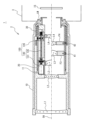
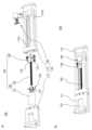
- FIG. 1 is a cross-sectional view showing the configuration of a camera equipped with a lens barrel according to an embodiment.
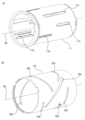
- FIG. 2A is a perspective view of the second fixed barrel
- FIG. 2B is a perspective view of the zoom cam ring.
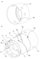
- FIG. 3A is a perspective view of the zoom rotation limit ring
- FIG. 3B is a perspective view showing the relationship between the second fixed barrel, the zoom cam ring, and the zoom rotation limit ring.
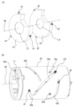
- FIG. 4A is a perspective view showing the configuration of the lens holding frame
- FIG. 4B is a perspective view showing the relationship between the cam pins, the second fixed barrel, and the zoom cam ring.
- FIG. 5A is a perspective view showing the drive mechanism in an exploded state
- FIG. 5B is a perspective view showing the drive mechanism in an assembled state.
- FIG. 6A is a perspective view illustrating the configuration of the connecting portion
- FIG. 6B is a cross-sectional view illustrating the configuration of the connecting portion.
- 7A and 7B are diagrams for explaining the configuration of the lead screw support mechanism.
- 8A to 8D are diagrams for explaining the configuration of the moving section.
- FIG. 9 is a side view of the drive mechanism.
- FIG. 10A is a perspective view of a drive mechanism according to the first modified example
- FIGS. 10B and 10C are diagrams for explaining the configuration of the drive mechanism according to the first modified example.
- 11A is a cross-sectional view of a moving portion according to the second modification
- FIG. 11B is a cross-sectional view of a connecting portion according to the third modification.
- FIG. 1 is a cross-sectional view showing the configuration of a camera 1 equipped with a lens barrel 2 according to one embodiment, with the wide-angle state shown above the center line and the telephoto state shown below.
- the camera 1 comprises a camera body 3 and a lens barrel 2.
- the lens barrel 2 is provided with a lens mount LM at the rear (base end) and is removably attached to the camera body 3 by engaging with a body mount (not shown) of the camera body 3.
- the lens barrel 2 is detachable from the camera body 3, but this is not limited thereto, and the lens barrel 2 and the camera body 3 may be integrated.
- the camera body 3 includes an image sensor IS and a control unit (not shown) inside.
- the image sensor IS is composed of a photoelectric conversion element such as a CCD (Charge Coupled Device), and converts the subject image formed by the imaging optical system (the lens barrel 2 attached to the camera body 3) into an electrical signal.
- CCD Charge Coupled Device
- the control unit includes a CPU (Central Processing Unit) and generally controls the overall operation of the camera 1 related to photography, including the focusing drive of the camera body 3 and the attached lens barrel 2.
- CPU Central Processing Unit
- the lens barrel 2 has lens groups L1 to L4 arranged in sequence along a common optical axis OA.
- Lens groups L1 and L2 are held by a first fixed cylinder 10 provided in the lens barrel 2
- lens groups L3 and L4 are held by lens holding frames F3 and F4, respectively.
- each of lens groups L3 and L4 is a zoom lens group that moves in the direction of the optical axis OA during zooming.
- the first fixed barrel 10 is composed of multiple parts, but it may also be composed of a single part.
- each of the lens groups L1 to L4 may be composed of a single lens, or may be composed of multiple lenses.
- a lens barrel composed of four lens groups is described as an example, the number of lens groups may be three or less, or five or more.
- the lens barrel 2 includes a second fixed barrel 11, a zoom cam ring 20 arranged radially outward from the second fixed barrel 11, and a zoom rotation limit ring 30 arranged radially outward from the zoom cam ring 20.
- Fig. 2(A) is a perspective view of the second fixed barrel 11
- Fig. 2(B) is a perspective view of the zoom cam ring 20
- Fig. 3(A) is a perspective view of the zoom rotation limit ring 30
- Fig. 3(B) is a perspective view showing the relationship between the second fixed barrel 11, the zoom cam ring 20, and the zoom rotation limit ring 30.
- the second fixed barrel 11 has an escape groove 11a, a first rectilinear groove 11b, and a second rectilinear groove 11c.
- the escape groove 11a, the first rectilinear groove 11b, and the second rectilinear groove 11c extend in a direction parallel to the optical axis OA.
- One escape groove 11a is provided in the circumferential direction of the second fixed barrel 11, three first rectilinear grooves 11b are provided in the circumferential direction, and three second rectilinear grooves 11c are provided in the circumferential direction.
- the number of first rectilinear grooves 11b and second rectilinear grooves 11c is not limited to three, and may be two or less, or four or more.
- the zoom cam ring 20 has a first cam groove 20a, a second cam groove 20b, a third cam groove 20c, and a zoom rotation limiting pin 20d.
- first cam groove 20a provided in the circumferential direction of the zoom cam ring 20
- second cam grooves 20b provided in the circumferential direction
- third cam grooves 20c provided in the circumferential direction.
- the zoom rotation limit ring 30 has a notch 30a.
- the second fixed barrel 11, zoom cam ring 20, and zoom rotation limit ring 30 are arranged in that order from the inner circumference side.
- the zoom cam ring 20 and the zoom rotation limit ring 30 are arranged so that the zoom rotation limit pin 20d of the zoom cam ring 20 is located within the cutout portion 30a of the zoom rotation limit ring 30.
- the zoom rotation limit pin 20d comes into contact with the end of the cutout portion 30a when the zoom cam ring 20 rotates a predetermined amount around the optical axis OA.
- the rotation of the zoom cam ring 20 around the optical axis OA is limited by the cutout portion 30a.
- FIG. 4(A) is a perspective view showing the configuration of the lens holding frames F3 and F4.
- the lens holding frames F3 and F4 are disposed inside the second fixed barrel 11.
- the outer peripheral surface of the lens holding frame F3 is provided with three cam pins 41 in the circumferential direction, protruding in a direction intersecting with the optical axis OA.
- the outer peripheral surface of the lens holding frame F4 is provided with three cam pins 42 in the circumferential direction, protruding in a direction intersecting with the optical axis OA.
- the number of cam pins 41 and cam pins 42 is not limited to three, and may be two or less, or four or more.
- the cam pins 41 correspond to the second protrusion
- the cam pins 42 correspond to the fourth protrusion.
- Figure 4 (B) is a perspective view showing the relationship between the cam pins 41 and 42, the second fixed barrel 11, and the zoom cam ring 20.
- the cam pin 41 of the lens holding frame F3 passes through the first linear groove 11b of the second fixed barrel 11 and engages with the second cam groove 20b of the zoom cam ring 20.
- the zoom cam ring 20 rotates, the lens holding frame F3 moves linearly in the direction of the optical axis OA along the first linear groove 11b and the second cam groove 20b.
- the cam pin 42 of the lens holding frame F4 passes through the second linear groove 11c of the second fixed barrel 11 and engages with the third cam groove 20c of the zoom cam ring 20.
- the zoom cam ring 20 rotates, the lens holding frame F4 moves linearly in the direction of the optical axis OA along the second linear groove 11c and the third cam groove 20c.
- FIG. 1 is a perspective view showing the drive mechanism 100 in a disassembled state
- Figure 5 (B) is a perspective view showing the drive mechanism 100 in an assembled state.
- the drive mechanism 100 includes a main body 150 and a support 110 that supports the main body 150.
- the support 110 includes a motor support 111, a guide 112, and a lead screw support mechanism 140.
- the motor support 111 supports the motor 131 included in the main body 150.
- the guide 112 has a linear groove 112a that engages with a linear groove engagement portion 123 included in the moving portion 120 (described later) and guides the moving portion 120 in the axial direction of the lead screw 135.
- the support 110 is fixed to the second fixed barrel 11 so that the axis of the lead screw 135 is parallel to the optical axis OA.
- the main body 150 includes a drive unit 130 and a moving unit 120.
- the drive unit 130 includes a motor 131 and a lead screw 135.
- the motor 131 can be, for example, a stepping motor or an ultrasonic motor.
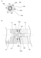
- FIG. 6(A) is a perspective view illustrating the configuration of the connecting portion 136
- FIG. 6(B) is a cross-sectional view illustrating the configuration of the connecting portion 136.
- the coupling portion 136 includes a connection portion 136c, a bearing 136b, a housing portion 136a, and an alignment portion 136d.
- the connection portion 136c connects the output shaft of the motor 131 to the lead screw 135.
- a connection member 137 is attached to the output shaft of the motor 131, and the output shaft of the motor 131 and the lead screw 135 are connected (coupled) by inserting the connection member 137 and one end of the lead screw 135 into the connection portion 136c.
- connection part 136c fits into the inner ring of the bearing 136b, and the outer ring of the bearing 136b fits into the inner wall of the accommodation part 136a. This allows the connection part 136c to be rotatably supported in the accommodation part 136a. This reduces the load on the motor 131 compared to when the connection part between the output shaft of the motor 131 and the lead screw 135 is supported without using the bearing 136b.
- the accommodation portion 136a is annular and has a through hole 139 penetrating the accommodation portion 136a.
- six through holes 139 are provided at equal intervals in the circumferential direction of the accommodation portion 136a, and an alignment portion 136d is inserted into each of the through holes 139.
- the alignment portion 136d is, for example, a bolt, and the degree of contact between the alignment portion 136d and the outer ring of the bearing 136b can be adjusted by moving the alignment portion 136d in the radial direction of the accommodation portion 136a.
- connection portion 136 has an alignment mechanism.
- FIGS. 7(A) and 7(B) are diagrams for explaining the configuration of the lead screw support mechanism 140.
- FIG. 7(A) is an exploded view of the lead screw support mechanism 140
- FIG. 7(B) is a cross-sectional view of the lead screw support mechanism 140.
- the lead screw support mechanism 140 is attached to the guide portion 112.
- the lead screw support mechanism 140 includes a housing portion 141, a compression spring 142, a backlash removing member 143, a bearing 144, and a screw 145.
- the storage section 141 stores a compression spring 142, a backlash-removing member 143, and a bearing 144.
- a hole 141a is formed in the storage section 141, into which a screw 145 is inserted. The screw 145 is inserted into the hole 141a, and prevents the bearing 144 from coming out of the storage section 141.
- the end of the lead screw 135 fits into the inner ring of the bearing 144, and the outer ring of the bearing 144 fits into the inner wall of the housing 141. This allows the lead screw support mechanism 140 to rotatably support the lead screw 135 and reduce frictional resistance when the lead screw 135 rotates. This reduces the load on the motor 131.
- the compression spring 142 biases the outer ring of the bearing 144 toward the lead screw 135 via the backlash elimination member 143.
- the backlash elimination member 143 has an outer edge portion 143a that contacts the outer ring of the bearing 144 and an engagement portion 143b that engages with the compression spring 142, and the compression spring 142 biases the backlash elimination member 143 toward the lead screw 135, so that the outer edge portion 143a biases the outer ring of the bearing 144 toward the lead screw 135. This makes it possible to suppress axial backlash caused by the axial internal gap of the bearing 144.
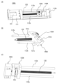
- Figures 8(A) to 8(D) are diagrams for explaining the configuration of the moving part 120. Note that Figures 8(A) and 8(B) are perspective views of the moving part 120 seen from different directions, Figure 8(C) is an exploded perspective view of the moving part 120, and Figure 8(D) is a cross-sectional view of the moving part 120.
- the moving part 120 includes a support part 121, a cam groove engagement part 122 corresponding to the first protrusion, a linear groove engagement part 123 corresponding to the third protrusion, a lead screw engagement part 124, and a biasing part 125.
- the support portion 121 supports the cam groove engagement portion 122, the linear groove engagement portion 123, the lead screw engagement portion 124, and the biasing portion 125.
- the cam groove engagement portion 122 penetrates the escape groove 11a (see FIG. 2A) of the second fixed barrel 11 and engages with the first cam groove 20a (see FIG. 2B) of the zoom cam ring 20 (see FIG. 4B). As a result, when the moving portion 120 (cam groove engagement portion 122) moves in the axial direction of the lead screw 135, the zoom cam ring 20 rotates.
- the cam groove engagement portion 122 includes a fixed portion 122a, an annular member 122b, and a bearing 122c.
- the fixed portion 122a is fixed to the support portion 121.
- the outer periphery of the fixed portion 122a is fitted into the inner ring of the bearing 122c.
- the outer ring of the bearing 122c is fitted into the inner wall of the annular member 122b. This allows the annular member 122b to be rotatably supported by the support portion 121. Since the annular member 122b is rotatable, the friction when the cam groove engagement portion 122 moves in the first cam groove 20a of the zoom cam ring 20 is rolling friction. Since the rolling friction is much smaller than the sliding friction, the load on the motor 131 when the cam groove engagement portion 122 moves in the first cam groove 20a of the zoom cam ring 20 can be reduced compared to when the annular member 122b cannot rotate.
- FIG. 9 is a side view of the drive mechanism 100.
- the linear groove engagement portion 123 includes a bearing 123a and an annular member 123b.
- the inner ring of the bearing 123a is fitted to the outer periphery of the protrusion 121a of the support portion 121.
- the outer ring of the bearing 123a is fitted to the inner wall of the annular member 123b. This allows the annular member 123b to be rotatably supported by the support portion 121. Since the annular member 123b is rotatable, the friction generated when the linear groove engagement portion 123 moves in the linear groove 112a is rolling friction. Therefore, compared to a case in which the annular member 123b cannot rotate, the load on the motor 131 when the linear groove engagement portion 123 moves in the linear groove 112a can be reduced.
- the lead screw engagement portion 124 includes an annular member 124a and a bearing 124b.
- the outer periphery of the annular member 124a is fitted into the inner ring of the bearing 124b.
- a groove 127 that comes into contact with the thread groove of the lead screw 135 is formed on the inner periphery of the annular member 124a.
- the groove 127 is a circumferential groove formed around the entire inner periphery of the annular member 124a.
- the annular member 124a is urged toward the lead screw 135 in a direction perpendicular to the axial direction of the lead screw 135 by the biasing portion 125, which is a leaf spring, as shown by the arrow A1 in FIG. 8(D).
- the biasing portion 125 which is a leaf spring, as shown by the arrow A1 in FIG. 8(D).
- the groove 127 of the annular member 124a is pressed against the thread groove of the lead screw 135, suppressing play between the annular member 124a and the lead screw 135.
- a part of the bearing 124b is housed in the housing portion 121b of the support portion 121, so that the support portion 121 and the lead screw engagement portion 124 are connected.
- the annular member 124a may be urged toward the lead screw 135 by other biasing members.
- the annular member 124a Since the annular member 124a is supported rotatably, when the lead screw 135 rotates, the annular member 124a is pushed by the flank surface of the thread groove of the lead screw 135 and moves in the axial direction of the lead screw 135 while rotating. As a result, the support part 121 supporting the annular member 124a also moves in the axial direction of the lead screw 135, so that the moving part 120 can be moved in the direction of the optical axis OA. In addition, since the annular member 124a moves in the axial direction of the lead screw 135 while rotating, the friction generated between the annular member 124a and the lead screw 135 becomes rolling friction. This makes it possible to reduce the load on the motor 131 when moving the moving part 120 in the axial direction of the lead screw 135. As the structure of the lead screw engagement part 124, the structure disclosed in Patent Application No. 2021-156263 may be applied.
- the cam groove engagement portion 122 of the moving portion 120 engages with the first cam groove 20a of the zoom cam ring 20, so when the moving portion 120 moves in the direction of the optical axis OA to rotate the zoom cam ring 20, the lens holding frame F3 moves linearly in the direction of the optical axis OA along the first linear groove 11b and the second cam groove 20b, and the lens holding frame F4 moves linearly in the direction of the optical axis OA along the second linear groove 11c and the third cam groove 20c. Because the zoom cam ring 20 is rotated using the first cam groove 20a, it is quieter than when the zoom cam ring 20 is rotated using gears.
- the lens barrel 2 includes a moving section 120 having a cam groove engaging section 122, a driving section 130 that moves the moving section 120 linearly in the optical axis OA direction, a zoom cam ring 20 having a first cam groove 20a and a second cam groove 20b that engage with the cam groove engaging section 122, and a lens holding frame F3 that has a cam pin 41 that engages with the second cam groove 20b and holds a lens group L3.
- the movement of the moving section 120 in the optical axis OA direction rotates the zoom cam ring 20, and the rotation of the zoom cam ring 20 moves the lens holding frame F3 in the optical axis OA direction. Because the zoom cam ring 20 is rotated using the first cam groove 20a, the sound generated when rotating the zoom cam ring 20 can be reduced compared to when the zoom cam ring 20 is rotated using a gear.
- the moving part 120 includes a linear groove engagement part 123
- the lens barrel 2 includes a guide part 112 having a linear groove 112a that engages with the linear groove engagement part 123. This allows the moving part 120 to move linearly in the direction of the optical axis OA.
- the cam groove engagement portion 122 (annular member 122b) can rotate around the center of the cam groove engagement portion 122. This reduces the load on the motor 131 when the cam groove engagement portion 122 moves within the first cam groove 20a, compared to when the cam groove engagement portion 122 (annular member 122b) cannot rotate. This allows the zoom cam ring 20 to rotate faster than when the cam groove engagement portion 122 (annular member 122b) cannot rotate (when sliding friction occurs) when the motor 131 with the same output is used to rotate a zoom cam ring 20 of the same weight.
- the zoom cam ring 20 that is heavier can be rotated than when the cam groove engagement portion 122 (annular member 122b) is supported so that it cannot rotate (when sliding friction occurs). Furthermore, when rotating a zoom cam ring 20 of the same weight, a motor 131 with a smaller output can be used than when the cam groove engagement portion 122 (annular member 122b) is supported so that it cannot rotate (when sliding friction occurs), allowing the drive mechanism 100 to be made smaller.
- the linear groove engagement portion 123 (annular member 123b) can rotate around the center of the linear groove engagement portion 123. This can reduce the load on the motor 131 when the linear groove engagement portion 123 moves within the linear groove 112a, compared to when the linear groove engagement portion 123 (annular member 123b) cannot rotate. This allows the zoom cam ring 20 to rotate faster than when the linear groove engagement portion 123 (annular member 123b) cannot rotate (when sliding friction occurs) when the motor 131 with the same output is used to rotate a zoom cam ring 20 of the same weight.
- the zoom cam ring 20 that is heavier can be rotated than when the linear groove engagement portion 123 (annular member 123b) is supported so that it cannot rotate (when sliding friction occurs). Furthermore, when rotating a zoom cam ring 20 of the same weight, a motor 131 with a smaller output can be used than when the linear groove engagement portion 123 (annular member 123b) is supported so that it cannot rotate (when sliding friction occurs), allowing the drive mechanism 100 to be made smaller.
- the moving part 120 has multiple linear groove engagement parts 123. This allows the moving part 120 to be stably guided in the optical axis OA direction.
- the zoom cam ring 20 further has a third cam groove 20c.
- the lens barrel 2 also has a cam pin 42 that engages with the third cam groove 20c, and is equipped with a lens holding frame F4 that holds the lens group L4, and the lens holding frame F4 moves in the direction of the optical axis OA as the zoom cam ring 20 rotates.
- This allows the multiple lens groups L3 and L4 to be moved in the direction of the optical axis OA by a single motor 131, thereby reducing power consumption compared to when multiple motors are provided to drive multiple lens groups.
- the drive unit 130 includes a motor 131 having an output shaft and a lead screw 135, the output shaft and the lead screw 135 are connected by a connecting unit 136, and the connecting unit 136 has a centering mechanism that adjusts the position of the axis of the output shaft and the position of the axis of the lead screw 135. This makes it possible to reduce vibrations and noise caused by misalignment between the axis of the output shaft of the motor 131 and the axis of the lead screw 135.
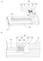
- Fig. 10(A) is a perspective view of the drive mechanism 100A according to the first modification
- Fig. 10(B) and Fig. 10(C) are perspective views showing the guide part 112A, the moving part 120A, and the lead screw support mechanism 140A according to the first modification.
- the guide portion 112A includes a guide bar 112b that extends parallel to the axial direction of the lead screw 135.
- the guide bar 112b is supported by a lead screw support mechanism 140A.
- the support portion 121A of the moving portion 120A has two through holes 121c, and the guide bar 112b is inserted into each of the through holes 121c.
- the moving portion 120A is guided by the guide bar 112b in the axial direction of the lead screw 135 (i.e., the direction of the optical axis OA).
- the zoom cam ring 20 is disposed on the outer periphery of the second fixed barrel 11, but this is not limited to the above.
- the zoom cam ring 20 may be disposed on the inner periphery of the second fixed barrel 11.
- a lens holding frame that holds a lens group different from lens groups L3 and L4 may be connected to the moving unit 120, and the lens holding frame may be moved in the direction of the optical axis OA by the moving unit 120.
- the moving unit 120 and the lens holding frame may be moved in the direction of the optical axis OA as a unit.
- the three lens holding frames can be moved linearly in the direction of the optical axis OA by a single motor 131.
- the bearing 124b provided in the lead screw engagement portion 124 of the moving portion 120 is not limited to a bearing, and may be any rotating rolling element that can rotate like a bearing. Also, the bearing 124b and the annular member 124a may be integrated.
- the lead screw engagement portion 124 of the moving portion 120 includes the annular member 124a and the bearing 124b, but this is not limited to this.
- the lead screw engagement portion 124 may include, for example, only the annular member 124a. In other words, the annular member 124a does not have to rotate.
- FIG. 11(A) is a cross-sectional view of a moving portion 120B according to Modification 2. As shown in FIG. 11(A), for example, a thread groove 128 that engages with the thread groove of the lead screw 135 over the entire circumference may be formed in the support portion 121B.
- the linear groove engagement portion 123 of the moving portion 120 does not have to include a bearing 123a.
- the annular member 123b may be supported so that it cannot rotate.
- FIG. 11 (B) is a cross-sectional view showing a connecting part 136A according to the third modification.
- the output shaft of the motor 131 and the lead screw 135 may be directly connected, for example, by a connecting part 136A that does not have an alignment mechanism. Also, the output shaft of the motor 131 and the lead screw 135 may be connected using an existing coupling (shaft joint).
Landscapes
- Physics & Mathematics (AREA)
- General Physics & Mathematics (AREA)
- Optics & Photonics (AREA)
- Engineering & Computer Science (AREA)
- General Engineering & Computer Science (AREA)
- Lens Barrels (AREA)
Priority Applications (4)
| Application Number | Priority Date | Filing Date | Title |
|---|---|---|---|
| US19/109,189 US20260086431A1 (en) | 2022-10-19 | 2023-10-17 | Lens barrel and imaging device |
| CN202380072460.2A CN120077309A (zh) | 2022-10-19 | 2023-10-17 | 镜头镜筒以及拍摄装置 |
| JP2024551814A JPWO2024085135A1 (https=) | 2022-10-19 | 2023-10-17 | |
| EP23879778.1A EP4607257A4 (en) | 2022-10-19 | 2023-10-17 | LENS CAP AND IMAGING DEVICE |
Applications Claiming Priority (2)
| Application Number | Priority Date | Filing Date | Title |
|---|---|---|---|
| JP2022167615 | 2022-10-19 | ||
| JP2022-167615 | 2022-10-19 |
Publications (1)
| Publication Number | Publication Date |
|---|---|
| WO2024085135A1 true WO2024085135A1 (ja) | 2024-04-25 |
Family
ID=90737780
Family Applications (1)
| Application Number | Title | Priority Date | Filing Date |
|---|---|---|---|
| PCT/JP2023/037495 Ceased WO2024085135A1 (ja) | 2022-10-19 | 2023-10-17 | レンズ鏡筒及び撮像装置 |
Country Status (5)
| Country | Link |
|---|---|
| US (1) | US20260086431A1 (https=) |
| EP (1) | EP4607257A4 (https=) |
| JP (1) | JPWO2024085135A1 (https=) |
| CN (1) | CN120077309A (https=) |
| WO (1) | WO2024085135A1 (https=) |
Citations (7)
| Publication number | Priority date | Publication date | Assignee | Title |
|---|---|---|---|---|
| JP2001264613A (ja) * | 2000-03-17 | 2001-09-26 | Fuji Photo Optical Co Ltd | レンズ装置 |
| JP2009169160A (ja) * | 2008-01-17 | 2009-07-30 | Canon Inc | レンズ駆動装置 |
| JP2017167511A (ja) * | 2016-03-09 | 2017-09-21 | キヤノン株式会社 | レンズ鏡筒、及び撮像装置 |
| JP2019133009A (ja) | 2018-01-31 | 2019-08-08 | キヤノン株式会社 | レンズ鏡筒および撮像装置 |
| JP2020177064A (ja) * | 2019-04-16 | 2020-10-29 | キヤノン株式会社 | 光学機器 |
| JP2021051181A (ja) * | 2019-09-25 | 2021-04-01 | 株式会社ニコン | レンズ鏡筒及びレンズ鏡筒の調芯方法 |
| JP2021156263A (ja) | 2020-03-30 | 2021-10-07 | スズキ株式会社 | 内燃機関の燃料噴射装置 |
Family Cites Families (4)
| Publication number | Priority date | Publication date | Assignee | Title |
|---|---|---|---|---|
| JP4774859B2 (ja) * | 2005-08-18 | 2011-09-14 | パナソニック株式会社 | 沈胴ズーム式レンズ鏡筒 |
| US10302899B2 (en) * | 2016-03-09 | 2019-05-28 | Canon Kabushiki Kaisha | Zoom-type lens barrel and image pickup apparatus |
| JP7005295B2 (ja) * | 2017-11-08 | 2022-01-21 | キヤノン株式会社 | 撮像ユニット及び撮像装置 |
| WO2020137563A1 (ja) * | 2018-12-28 | 2020-07-02 | 株式会社ニコン | レンズ鏡筒および光学機器 |
-
2023
- 2023-10-17 JP JP2024551814A patent/JPWO2024085135A1/ja active Pending
- 2023-10-17 CN CN202380072460.2A patent/CN120077309A/zh active Pending
- 2023-10-17 EP EP23879778.1A patent/EP4607257A4/en active Pending
- 2023-10-17 WO PCT/JP2023/037495 patent/WO2024085135A1/ja not_active Ceased
- 2023-10-17 US US19/109,189 patent/US20260086431A1/en active Pending
Patent Citations (7)
| Publication number | Priority date | Publication date | Assignee | Title |
|---|---|---|---|---|
| JP2001264613A (ja) * | 2000-03-17 | 2001-09-26 | Fuji Photo Optical Co Ltd | レンズ装置 |
| JP2009169160A (ja) * | 2008-01-17 | 2009-07-30 | Canon Inc | レンズ駆動装置 |
| JP2017167511A (ja) * | 2016-03-09 | 2017-09-21 | キヤノン株式会社 | レンズ鏡筒、及び撮像装置 |
| JP2019133009A (ja) | 2018-01-31 | 2019-08-08 | キヤノン株式会社 | レンズ鏡筒および撮像装置 |
| JP2020177064A (ja) * | 2019-04-16 | 2020-10-29 | キヤノン株式会社 | 光学機器 |
| JP2021051181A (ja) * | 2019-09-25 | 2021-04-01 | 株式会社ニコン | レンズ鏡筒及びレンズ鏡筒の調芯方法 |
| JP2021156263A (ja) | 2020-03-30 | 2021-10-07 | スズキ株式会社 | 内燃機関の燃料噴射装置 |
Non-Patent Citations (1)
| Title |
|---|
| See also references of EP4607257A4 |
Also Published As
| Publication number | Publication date |
|---|---|
| JPWO2024085135A1 (https=) | 2024-04-25 |
| EP4607257A1 (en) | 2025-08-27 |
| US20260086431A1 (en) | 2026-03-26 |
| CN120077309A (zh) | 2025-05-30 |
| EP4607257A4 (en) | 2025-12-17 |
Similar Documents
| Publication | Publication Date | Title |
|---|---|---|
| US7039308B2 (en) | Cam mechanism of a photographing lens | |
| US6963694B2 (en) | Lens barrel | |
| US7079762B2 (en) | Supporting structure for supporting a rotatable ring | |
| US7062163B2 (en) | Cam mechanism of a photographing lens | |
| US7010224B2 (en) | Lens barrel incorporating the rotation transfer mechanism | |
| JP7679885B2 (ja) | レンズ鏡筒、撮像装置、及び駆動装置 | |
| JP7059037B2 (ja) | レンズ鏡筒及び撮像装置 | |
| US7663810B2 (en) | Lens barrel and method for manufacturing the same | |
| JP2026020399A (ja) | レンズ鏡筒及び撮像装置 | |
| WO2024085135A1 (ja) | レンズ鏡筒及び撮像装置 | |
| US12591108B2 (en) | Lens barrel and imaging apparatus | |
| JP2005202316A (ja) | 中空モータ一体型レンズ鏡筒 | |
| JP2004109830A (ja) | レンズ鏡筒 | |
| CN1864085A (zh) | 透镜镜筒 | |
| US8238041B2 (en) | Lens barrel | |
| JP7191660B2 (ja) | レンズ鏡筒および光学機器 | |
| JP2003035856A (ja) | レンズ鏡筒、投射型画像表示装置および光学機器 | |
| JP2015026062A (ja) | レンズ鏡筒 | |
| US20240264406A1 (en) | Optical apparatus and imaging apparatus | |
| WO2025047307A1 (ja) | 駆動機構、レンズ鏡筒、および撮像装置 | |
| JP2021196472A (ja) | レンズ鏡筒及び撮像装置 | |
| JP6022412B2 (ja) | レンズ装置 | |
| WO2025047243A1 (ja) | レンズ鏡筒および撮像装置 | |
| JP2010271525A (ja) | レンズ鏡筒及びその組立方法 | |
| JP2026005107A (ja) | レンズ鏡筒及び撮像装置 |
Legal Events
| Date | Code | Title | Description |
|---|---|---|---|
| 121 | Ep: the epo has been informed by wipo that ep was designated in this application |
Ref document number: 23879778 Country of ref document: EP Kind code of ref document: A1 |
|
| WWE | Wipo information: entry into national phase |
Ref document number: 2024551814 Country of ref document: JP |
|
| WWE | Wipo information: entry into national phase |
Ref document number: 202380072460.2 Country of ref document: CN |
|
| WWE | Wipo information: entry into national phase |
Ref document number: 2023879778 Country of ref document: EP |
|
| NENP | Non-entry into the national phase |
Ref country code: DE |
|
| ENP | Entry into the national phase |
Ref document number: 2023879778 Country of ref document: EP Effective date: 20250519 |
|
| WWP | Wipo information: published in national office |
Ref document number: 202380072460.2 Country of ref document: CN |
|
| WWP | Wipo information: published in national office |
Ref document number: 2023879778 Country of ref document: EP |