WO2024084984A1 - Dispositif de nettoyage de matériau filtrant - Google Patents
Dispositif de nettoyage de matériau filtrant Download PDFInfo
- Publication number
- WO2024084984A1 WO2024084984A1 PCT/JP2023/036338 JP2023036338W WO2024084984A1 WO 2024084984 A1 WO2024084984 A1 WO 2024084984A1 JP 2023036338 W JP2023036338 W JP 2023036338W WO 2024084984 A1 WO2024084984 A1 WO 2024084984A1
- Authority
- WO
- WIPO (PCT)
- Prior art keywords
- screw
- filter
- cleaning device
- filtration
- layer
- Prior art date
Links
- 238000001914 filtration Methods 0.000 title claims abstract description 116
- 239000000463 material Substances 0.000 title claims abstract description 103
- 238000004140 cleaning Methods 0.000 title claims abstract description 88
- XLYOFNOQVPJJNP-UHFFFAOYSA-N water Substances O XLYOFNOQVPJJNP-UHFFFAOYSA-N 0.000 claims abstract description 87
- 238000005406 washing Methods 0.000 description 15
- 239000006260 foam Substances 0.000 description 10
- 239000000356 contaminant Substances 0.000 description 9
- 239000008213 purified water Substances 0.000 description 9
- 238000011001 backwashing Methods 0.000 description 8
- 230000007246 mechanism Effects 0.000 description 8
- 230000009467 reduction Effects 0.000 description 8
- 230000000694 effects Effects 0.000 description 7
- 238000000034 method Methods 0.000 description 6
- 230000002265 prevention Effects 0.000 description 6
- 230000002093 peripheral effect Effects 0.000 description 5
- 230000000052 comparative effect Effects 0.000 description 4
- 239000002184 metal Substances 0.000 description 4
- 239000004576 sand Substances 0.000 description 4
- 239000003344 environmental pollutant Substances 0.000 description 3
- 239000012466 permeate Substances 0.000 description 3
- 231100000719 pollutant Toxicity 0.000 description 3
- 230000008569 process Effects 0.000 description 3
- 239000000919 ceramic Substances 0.000 description 2
- 238000005192 partition Methods 0.000 description 2
- 230000009471 action Effects 0.000 description 1
- 230000008901 benefit Effects 0.000 description 1
- 238000007599 discharging Methods 0.000 description 1
- 238000006073 displacement reaction Methods 0.000 description 1
- 230000005484 gravity Effects 0.000 description 1
- -1 i.e. Substances 0.000 description 1
- 230000006872 improvement Effects 0.000 description 1
- 238000003780 insertion Methods 0.000 description 1
- 230000037431 insertion Effects 0.000 description 1
- 238000007689 inspection Methods 0.000 description 1
- 238000004898 kneading Methods 0.000 description 1
- 230000007774 longterm Effects 0.000 description 1
- 239000002245 particle Substances 0.000 description 1
- 238000005086 pumping Methods 0.000 description 1
- 238000000926 separation method Methods 0.000 description 1
- 229910001220 stainless steel Inorganic materials 0.000 description 1
- 239000010935 stainless steel Substances 0.000 description 1
- 239000013585 weight reducing agent Substances 0.000 description 1
Images

Definitions
- the present invention relates to a device for cleaning filter media in a filtration device that purifies raw water by passing it through the filter media.
- Patent Documents 1 and 2 for example, filtration devices that filter and purify raw water are known. These filtration devices basically have a layer of filtration material inside a filtration tank made of metal or the like, and the supplied raw water is filtered by passing through the layer of filtration material. With repeated use of this type of filtration device, the filtration material becomes dirty with captured fine suspended matter, etc., and it is necessary to discard or wash the filtration material as appropriate.
- methods widely used for washing this filtration material include surface washing, in which the surface of the filtration material layer is washed by hitting it with a water flow sprayed from a nozzle, and backflow washing, in which purified water is injected into the filtration material layer from below and the filtration material is rubbed and washed.
- This filter media cleaning device basically has a spiral screw (more specifically, the screw blade portion) arranged upright within the layer of filter media, and a screw drive means that rotates this screw around the screw axis, and by rotating the screw, the filter media is transported from the bottom to the top while being rubbed and washed.
- the filter cleaning device using the screw conveyor is described in detail with reference to FIG. 6, taking the device shown in Patent Document 1 as an example.
- the filter device 1 in which the filter cleaning device 14 is installed will be described. Note that in the figure, some parts are shown in a schematic manner, such as by showing the cross-sectional shape of a thick member with a single straight line.
- the filter device 1 has a substantially cylindrical filter tank 2 closed at the top and bottom, a filter bed 4 with many fine holes (not shown) arranged at the inside lower part of the filter tank 2, and filter material 6 stacked on the filter bed 4.
- a plurality of support legs 8 (only one is shown in the figure) are attached to the filter tank 2, which allows the filter tank 2 to be installed on the floor surface 10.
- a plurality of short cylindrical filters 12 made of ceramic with fine holes are installed in the filter bed 4. The filters 12 allow only purified water 16 to permeate below the filter bed 4.
- a circular mounting opening 22 is formed in the center of the upper wall 20 of the filtration tank, and the filter media cleaning device 14 is attached to this mounting opening 22.
- the periphery of the mounting opening 22 is formed into a mounting rim 24.
- a base 28 to which a motor 26 and a reduction mechanism 27 are attached is attached on the rim 24.
- a holding section 36 having bearings 30 in three places is formed on this base 28, and these three bearings 30 are configured to support the rotating shaft 34 of the screw conveyor 32 so that it can rotate freely without wobbling.
- the cylindrical tubular member 38 that constitutes the cleaning tank body in the filter media cleaning device 14 has a disk-shaped partition wall 29 at its upper part.
- a flange 31 on the outer periphery of the partition wall 29 is attached to the rim 24, and is attached to the rim 24 together with the base 28 by bolts.
- the upper part of the tubular member 38 is attached to the rim 24, and almost the entire tubular member 38 hangs down from the upper wall 20.
- a hole 33 is formed in the center of the flange 31, which is tightly fitted into the retaining portion 36. This makes it possible to maintain an airtight state inside the filtration tank 2 during filtration.
- the lower part of the tubular member 38 is an open circular lower opening 40, and multiple upper openings 42 are formed at the upper part.
- the multiple upper openings 42 are formed at a predetermined interval around the circumference of the tubular member 38, and each extends in the vertical direction.
- the positional relationship between the lower opening 40 and the filter material 6 is determined so that it is located inside the filter material 6.
- a screw conveyor 32 is arranged inside the tubular member 38.
- the screw conveyor 32 is formed from a rotating shaft 34, for example a hollow pipe, whose upper and lower parts have different diameters, and a helical screw blade portion 43 fixed to the outer circumferential surface of the lower part (relatively large diameter part) of the rotating shaft 34.
- the screw blade portion 43 is formed up to the lower end 44 of the rotating shaft 34.
- the upper end of the rotating shaft 34 of the screw conveyor 32 is connected to the reduction mechanism 27 of the motor 26 via a joint 52.
- the screw blade portion 43 When the screw blade portion 43 is thus positioned inside the tubular member 38, the upper end of the screw blade portion 43 is located near the lower edge 42a of the upper opening 42.
- the lower end portion 35 of the screw conveyor 32 protrudes downward from the lower opening 40 of the tubular member 38, and the lower end 44 of the rotating shaft 34 is located near the filter bed 4. Therefore, when the filter material 6 is washed, the filter material 6 near the filter bed 4 is also efficiently transported upward by the screw blade portion 43 and washed.
- a purified water discharge pipe 60 extending downward is attached to the center of the curved bottom wall 58 of the filtration tank 2, and water purified after passing through the filtration material 6, filter bed 4, and filter 12 is discharged through this purified water discharge pipe 60.
- a raw water inlet (turbidity discharge means) 62 for injecting raw water, i.e., water before filtration 16, into the filtration tank 2 during filtration, and a water level adjustment port 64 installed below it.
- the water level adjustment port 64 also functions as a discharge port for discharging water 16 in order to adjust the optimal water level for washing the filtration material 6.
- An inspection hatch 68 is provided on the top wall 20 of the filtration tank 2, and is used to check the condition inside the filtration tank 2, such as the top surface 66 of the filtration material 6.
- An air vent valve 70 is located to the left of the top wall 20 of the filtration tank 2.
- a filtration material insertion port 72 for inserting the filtration material 6 is provided on the side of the filtration tank 2.
- raw water to be filtered is pumped in through the raw water inlet 62 by a pump (not shown).
- a pump not shown
- air in the filter tank 2 is discharged through the air vent valve 70.
- the water level 74 is set so that it exceeds the raw water inlet 62 and reaches the top of the filter tank 2, that is, so that the filter tank 2 is almost entirely filled with water (raw water) 16.
- the water level 74 shown in FIG. 1 indicates a midway position before it is full.
- the water 16 permeates the filter material 6 and also enters the tubular member 38 through the upper opening 42 to permeate the filter material 6 in the tubular member 38, so that filtration can be performed even within the tubular member 38.
- the water that has permeated the filter material 6 and been filtered is discharged to the outside from the purified water discharge pipe 60 at the bottom of the filter tank 2 and is available for use.
- the dropped filter material 6 is again pushed up into the tubular member 38 by the blades 43 and kneaded and washed. In this way, the filter material 6 is repeatedly washed within the tubular member 38, and the contaminants are separated.
- the lower end 44 of the screw conveyor 32 is located near the filter bed 4, so the filter media 6 close to the filter bed 4 are also pushed up, and all of the filter media 6 are evenly washed.
- the above-mentioned filter media cleaning device has the effect of efficiently cleaning dirty filter media in a short time of about 7 minutes, compared to the 15 minutes required for conventional surface cleaning or backflow cleaning.
- the above has been described as being applied to a filtration tank, but filtration basins such as those shown in Patent Document 3 are also publicly known, and the above-mentioned filter media cleaning device can also be applied to such filtration basins, and in this case too, the filter media can be efficiently cleaned in a short time.
- the filter cleaning device comprises: A filter cleaning device for a filtration device having a layer of filter material inside a filtration tank or filtration basin, which filters supplied raw water by passing it through the layer of filter material, A filter material cleaning device having a helical screw arranged vertically within a layer of filter material and a screw driving means for rotating the screw about a screw axis, the device rotating the screw to knead and clean the filter material,
- the screw used is a screw in which a spiral screw blade portion constituting the screw is a plurality of screw blade portions that are not continuous with each other and are arranged apart from each other in the screw axial direction, The filter is transported upward while the outer periphery of the screw is in direct contact with the layer of filter.
- the screw arranged upright within the layer of filter material is most preferably arranged upright in the vertical direction, but is not limited to this and may be arranged at a slight angle inclined to the vertical direction. In this case, it is desirable for the angle of inclination to be at most about 10° (degrees).
- a screw having a coil spring shape is used as the screw. More specifically, this "coil spring shape” refers to a shape in which the helical screw blade portion constituting the screw forms a ring at a position away from the screw axis on the outer circumferential side when viewed from the screw axial direction (the direction in which the screw axis extends).
- the filter material washing device according to the present invention is based on this finding and does not require a cylindrical member, so that the filter material washing effect is the same as that of the conventional device, but the omission of the cylindrical member allows the device to be formed at low cost and with a lighter weight. This effect is most noticeable when the area where the cylindrical member is not provided is the entire length of the screw.
- the filter material cleaning device uses a screw in which the helical screw blade portion constituting the screw is a plurality of screw blade portions that are not continuous with each other and are arranged apart from each other in the screw axial direction. Therefore, compared to a case in which a screw with a single screw blade portion is used, a greater amount of filter material is transported, resulting in higher filter material cleaning efficiency.
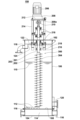
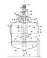
- FIG. 1 is a schematic side view of a filtration device having a filter media cleaning device according to an embodiment of the present invention.
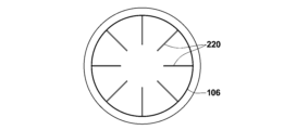
- FIG. 2 is a plan view showing a part of the filter media cleaning device of FIG.
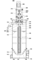
- FIG. 1 is a schematic side view showing a filtration device having a filter medium cleaning device as a comparative example of the present invention.
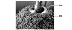
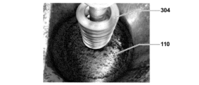
- a photograph showing a filter medium cleaned by the filter medium cleaning device of FIG. 1. A photograph showing a filter medium cleaned by the filter medium cleaning device of FIG. 3.
- FIG. 1 is a schematic side view showing a filtration device having a conventional filter media cleaning device.
- FIG. 1 is a schematic side view showing another example of a filtration device in which a filtration medium cleaning device according to the present invention is used.
- FIG. 1 shows a schematic side view of a filtration device 100 having a filter cleaning device according to an embodiment of the present invention. Note that the figure also shows some schematic views, such as a single straight line showing the cross-sectional shape of a thick member. First, the filtration device 100 will be described.
- the filtration device 100 has an upper end member 102 surrounding a circular opening, a substantially cylindrical filtration tank 106 having a bottom wall 104, a filter bed 108 with a large number of fine holes (not shown) arranged at the bottom inside the filtration tank 106, and a filter material 110 made of sand or the like having a specific gravity greater than water, layered on the filter bed 108.
- the filter bed 108 is equipped with a plurality of short cylindrical strainers 112 made of ceramic or the like having fine holes.
- This filtration device 100 is, as an example, a so-called upflow filtration device, and has a raw water inlet chamber 114 between the filter bed 108 and the bottom wall 104 inside the filtration tank 106.
- a raw water inlet pipe 115 that opens at a position close to the peripheral wall on the left side of the figure, and a backwash water inlet pipe 116 that opens at a position close to the peripheral wall on the right side of the figure are connected to this raw water inlet chamber 114.
- a treated water outlet pipe 118 that communicates with the inside of the filtration tank 106 is connected to a position slightly below the upper end member 102 of the filtration tank 106.
- a filter material outlet 120 that opens into the inside of the filtration tank 106 at a position slightly above the filter bed 108 is connected to the filtration tank 106.
- the filtration device 100 is provided with a horizontal cleaning port pipe that opens into the inside of the raw water inlet chamber 114, a water level adjustment outlet pipe that connects to the cleaning port pipe from above, etc., but these are not directly related to the present invention and may be formed in the same way as in conventional devices, so illustrations and detailed explanations are omitted.
- a filter cleaning device 200 according to one embodiment of the present invention is attached to the center of the filter tank 106. Details of this filter cleaning device 200 will be described later.
- raw water to be filtered is sent from the raw water inlet pipe 115 into the raw water inlet chamber 114 under a predetermined pressure.
- This raw water passes through multiple strainers 112 and then through a layer of filter material 110 from bottom to top. During this process, contaminants contained in the raw water are captured by the filter material, and the raw water is filtered.
- the treated water 122 overflows the dam plate 124 and is discharged from the treated water outlet pipe 118 to the outside of the filtration tank 106.
- the filter media cleaning device 200 has a rotating shaft 203 that extends vertically through the center of the filtration tank 106, and a spiral screw blade portion 204 fixed to the outer circumferential surface of the rotating shaft 203.
- the rotating shaft 203 is composed of a relatively small diameter upper shaft portion 201 and a relatively large diameter lower shaft portion 202, and the screw blade portion 204 is specifically fixed to the outer circumferential surface of the lower shaft portion 202.
- the rotating shaft 203 and the screw blade portion 204 form a screw conveyor.
- the screw blade portion 204 is composed of two screw blade portions that are not continuous with each other and are spaced apart from each other in the screw axial direction.
- a motor 206 and a speed reduction mechanism 208 that reduces the speed of the motor 206 are disposed above the filtration tank 106.
- the motor 206 and the speed reduction mechanism 208 constitute a screw drive means, and the output shaft 208a of the speed reduction mechanism 208 is connected to the shaft upper portion 201 of the rotating shaft 203 via a joint 210.
- the motor 206 and the speed reduction mechanism 208 are integrated and held on a holding member 212.
- the holding member 212 is fixed to the filtration tank 106 via a plurality of supports 214 extending in the vertical direction and a support 216 fixed to the inside of the upper portion of the filtration tank 106.
- the shaft upper portion 201 of the rotating shaft 203 is rotatably supported by, for example, four bearings 218 arranged at a distance from one another in the axial direction. This allows the rotating shaft 203 to rotate without wobbling.
- Inside the filtration tank 106 there are provided filter material flow prevention plates 220, one of which has a planar cross-sectional shape as shown in FIG. 2, surrounding the screw blade portion 204 at eight points on the outer periphery.
- These filter material flow prevention plates 220 are provided in three sets, for example, at a distance from one another in the direction in which the spiral of the screw blade portion 204 repeats, that is, in the axial direction of the rotating shaft 203.
- Each filter material flow prevention plate 220 is inclined with respect to the axial direction, but the direction of inclination is opposite to that of adjacent sets.
- the filter cleaning device 200 performs so-called backflow cleaning (backwashing).
- backwashing When performing this backwashing, during a period when the filtration of raw water is suspended, purified water as backwash water is sent from the backwash water inlet pipe 116 to the raw water inlet chamber 114 under a predetermined pressure.
- This purified water passes through the filter 110 from bottom to top and is discharged from the treated water outlet pipe 118 to the outside of the filtration tank 106. At that time, the contaminants captured by the filter 110 are peeled off from the filter 110 by the purified water and are discharged from the treated water outlet pipe 118 to the outside of the filtration tank 106 together with the purified water.
- the filter media can also be cleaned by the filter media cleaning device 200 as appropriate.
- the motor 206 is driven during the period when the raw water filtration is stopped and the backwashing is being performed, and the rotational force is transmitted to the rotating shaft 203 of the screw conveyor via the reduction mechanism 208.
- the rotating shaft 203 rotates in this manner, the helical screw blade portion 204 rotates, and the filter media 110 is transported upward by the screw blade portion 204.
- the individual filter media 110 are squeezed together, so that the captured pollutants are peeled off from the filter media 110.
- the pollutants are discharged from the filtration tank 106 together with the backwash water through the treated water outlet pipe 118.
- the screw blade portion 204 can function as a component of the screw conveyor, and the filter material 110 can be kneaded and washed while being transported upward by the rotating screw blade portion 204. This action is believed to be achieved as follows.
- the screw blade portion 204 As the screw blade portion 204 continues to rotate within the layer of filter material 110, the portion of filter material 110 in contact with its outer periphery is scraped off, and a roughly cylindrical space is defined within the layer of filter material 110. In other words, the screw blade portion 204 rotates within the space with its outer periphery facing the circumferential surface of the space.
- the filter material 110 is mainly made of sand, the circumferential surface of the space becomes a wall that can be called a "sand wall,” and functions just like a tubular member (outer tube) in a conventional device.
- the filter material 110 that is scattered outward due to the centrifugal force caused by the rotation of the screw blade portion 204 bounces off this "sand wall" and returns to the upper surface of the screw blade portion 204, and is rubbed and washed while being transported upward by the screw blade portion 204.
- the peripheral surface of the above space functions like the tubular member (outer tube) in the conventional device as described above, it is ultimately formed from the sand-like filter material 110, and therefore also exhibits the inherent properties of sand-like materials. In other words, even if the filter material 110 scattered around the outer periphery of the screw blade portion 204 collides with this peripheral surface as described above, the peripheral surface is only slightly deformed, and the scattered filter material 110 is not crushed.
- the filter material scattered around the outer periphery from the screw blade portion may collide with the tubular member made of metal or the like and be crushed.
- the filter media cleaning device 200 of this embodiment can be formed at a lower cost and with a lighter weight than conventional devices.
- the above-mentioned tubular member is usually formed from a metal such as stainless steel, and the distance between the screw blade portion and the tubular member must be precisely set to a predetermined value so that the filter media being kneaded and cleaned is not trapped between the inner surface of the tubular member and the screw blade portion and destroyed, which tends to increase costs. If such a tubular member can be eliminated, the effect of reducing costs will be particularly noticeable.
- the filter media cleaning device 200 can be formed to be lightweight, the filtration device 100 equipped with it can naturally also be made lighter.
- the overall length of the rotating shaft 203 and the screw blade portion 204 that constitute the screw conveyor together with the tubular member can be set larger when there is a weight limit on the screw conveyor, which is advantageous in forming a long filtration tank 106.
- three sets of filter media flow prevention plates 220 are provided to surround the screw blade portion 204 from eight points on the outer periphery, thereby obtaining the following effects. That is, if raw water containing turbidity (pollutants) is continuously filtered by the filter media layer (layer of filter media 110), the turbidity gradually clogs the lower part of the layer, and pressure is applied to the filter media layer during filtration. When clogging progresses in this way and the filtration pressure increases, the filtration pressure increases further with the filter media 110 and the turbidity integrated at the bottom of the layer.
- a filter cleaning device 300 will be described as a comparative example of the present invention.
- the filter cleaning device 300 is basically different from the filter cleaning device 200 in that the screw blade portion 204 in the filter cleaning device 200 of the above embodiment is composed of two screw blades, whereas the screw blade portion 304 in the filter cleaning device 300 is composed of one screw blade.
- the filter cleaning device 300 is provided in the filter device 150, and the filter device 150 is also different from the filter device 100 of FIG. 1 only in that the filter cleaning device 300 is used instead of the filter cleaning device 200. Therefore, in FIG. 3, the same elements as those in FIG. 1 are numbered the same as those in FIG. 1, and their explanation will be omitted unless otherwise necessary.
- the filter 110 is cleaned in the same manner as in the filter cleaning device 200 of the embodiment shown in FIG. 1.
- the screw blade portion 204 is composed of two screw blades, so the filter 110 can be transported and cleaned relatively efficiently
- the screw blade portion 304 is composed of one screw blade, so the efficiency of the transport and cleaning of the filter 110 is lower than in the above embodiment.
- the screw blade portion 204 is composed of two screw blade portions, but three or more screw blade portions may be used. In any case, using multiple screw blade portions in this way is advantageous in improving the efficiency of transporting and cleaning the filter media 110 compared to using a single screw blade portion.
- the above describes an embodiment of a filter material cleaning device installed in a filtration device having a filtration tank, but the filter material cleaning device of the present invention is not limited to such filtration devices and can also be installed in a filtration tank.
- the filter material cleaning devices 200 and 300 described above are applied to an upflow type filtration device, but the filter material cleaning device of the present invention is not limited to this and can also be applied to a downflow type filtration device such as that shown in Figure 6.
- FIG. 7 differs from the filtration device 100 shown in FIG. 1 in that the shape of the filter bed 108A is different. That is, while the filtration device 100 in FIG. 1 uses a simple circular filter bed 108, the filter bed 108A in the filtration device 400 of this example has a "funnel-like" or "mortar-like” shape that is concave downward and gradually narrows in diameter from the circular outer periphery toward the center.
- the filter bed 108A By making the filter bed 108A in this shape, the filter material 110 that is being transported upward and kneaded by the rotating screw blade portion 204 of the filter material cleaning device 200, and the contaminants that are torn off from the filter material and discharged from the treated water outlet pipe 118, tend to naturally gather near the lower end of the screw blade portion 204. This makes it possible to more efficiently knead and wash the filter material 110 and discharge the contaminants.
- the area of contact between the raw water before filtration and the filter media 110 via the filter bed 108A is larger than when the raw water comes into contact with the filter media 110 via the circular filter bed 108, which is also advantageous in speeding up filtration.
- the aforementioned backflow cleaning (backwashing) may be performed, but foam cleaning of the filter material may be performed in parallel with this backwashing, or independently as an alternative to this backwashing.
- This foam cleaning is a process in which foam cleaning water containing a large number of fine bubbles is flowed toward the filter material 110 from below the layer of the filter material 110.
- the foam cleaning water flows between the filter materials 110, and the contaminants captured on the surface of each filter material 110 are peeled off by the vibration, impact, and contact caused by the passing of the bubbles.
- the foam cleaning water containing the peeled contaminants is discharged outside the filtration tank 106 from the treated water outlet pipe 118, just like in the case of backwashing.
- the water for obtaining the foam washing water may be a part of the backwash water, or may be prepared separately from the backwash water.
- a non-positive displacement pump that rotates an impeller inside a casing can be used as a pump that pumps water toward the filter material 110, and the impeller can cut the water to generate bubbles.
- a dedicated foam generator that generates such bubbles can be installed in the water pumping path.
- REFERENCE SIGNS LIST 100, 150, 400 Filtration device 102 Upper end member of filtration tank 104 Bottom wall of filtration tank 106 Filtration tank 108, 108A Filter bed 110 Filter material 112 Strainer 114 Raw water inlet chamber 115 Raw water inlet pipe 116 Backwash water inlet pipe 118 Treated water outlet pipe 120 Filter material outlet 122 Treated water 124 Weir plate 200, 300 Filter material cleaning device 203 Rotating shaft 204, 304 Screw blade portion 206 Motor 208 Reduction mechanism portion 210 Joint 212 Holding member 214, 216 Support 218 Bearing 220 Filter material flow prevention plate
Abstract
[Problème] Former un dispositif de nettoyage de matériau filtrant à faible coût et léger qui nettoie un matériau filtrant disposé dans un réservoir de filtration ou similaire, par frottement au moyen d'une vis rotative disposée à l'intérieur de celui-ci. [Solution] Un dispositif de nettoyage de matériau filtrant (200) est destiné à être utilisé dans un appareil de filtration (100) qui comprend une couche de matériau filtrant (110) disposée à l'intérieur d'un réservoir de filtration ou similaire et dans lequel une filtration a lieu en faisant passer de l'eau brute fournie à celui-ci à travers la couche du matériau filtrant (110). Le dispositif de nettoyage de matériau filtrant comprend : une vis en spirale (204) qui est agencée de façon à se tenir érigée dans la couche du matériau filtrant (110) ; et un moyen d'entraînement de vis (206, 208) qui fait tourner ladite vis (204) autour d'un arbre à vis. Le dispositif de nettoyage de matériau filtrant (200) entraîne la vis (204) en rotation pour nettoyer le matériau filtrant (110) par frottement. Étant donné qu'il n'est pas prévu de cylindre externe entourant la vis (204), le matériau filtrant (110) est transféré vers le haut tout en maintenant un contact direct entre le bord circonférentiel externe de la vis (204) qui comporte une pluralité de lames de vis et la couche du matériau filtrant (110).
Applications Claiming Priority (2)
| Application Number | Priority Date | Filing Date | Title |
|---|---|---|---|
| JP2022-166083 | 2022-10-17 | ||
| JP2022166083A JP2024058776A (ja) | 2022-10-17 | 2022-10-17 | ろ過材洗浄装置 |
Publications (1)
| Publication Number | Publication Date |
|---|---|
| WO2024084984A1 true WO2024084984A1 (fr) | 2024-04-25 |
Family
ID=90737390
Family Applications (1)
| Application Number | Title | Priority Date | Filing Date |
|---|---|---|---|
| PCT/JP2023/036338 WO2024084984A1 (fr) | 2022-10-17 | 2023-10-05 | Dispositif de nettoyage de matériau filtrant |
Country Status (2)
| Country | Link |
|---|---|
| JP (1) | JP2024058776A (fr) |
| WO (1) | WO2024084984A1 (fr) |
Citations (3)
| Publication number | Priority date | Publication date | Assignee | Title |
|---|---|---|---|---|
| JP2007307549A (ja) * | 2006-04-21 | 2007-11-29 | Maezawa Ind Inc | 濾過装置及びこの濾過装置を用いた排水処理装置 |
| JP2013018020A (ja) * | 2011-07-11 | 2013-01-31 | Marsima Aqua System Corp | し渣分離脱水装置 |
| WO2019221048A1 (fr) * | 2018-05-14 | 2019-11-21 | 日本原料株式会社 | Dispositif de filtration |
-
2022
- 2022-10-17 JP JP2022166083A patent/JP2024058776A/ja active Pending
-
2023
- 2023-10-05 WO PCT/JP2023/036338 patent/WO2024084984A1/fr unknown
Patent Citations (3)
| Publication number | Priority date | Publication date | Assignee | Title |
|---|---|---|---|---|
| JP2007307549A (ja) * | 2006-04-21 | 2007-11-29 | Maezawa Ind Inc | 濾過装置及びこの濾過装置を用いた排水処理装置 |
| JP2013018020A (ja) * | 2011-07-11 | 2013-01-31 | Marsima Aqua System Corp | し渣分離脱水装置 |
| WO2019221048A1 (fr) * | 2018-05-14 | 2019-11-21 | 日本原料株式会社 | Dispositif de filtration |
Also Published As
| Publication number | Publication date |
|---|---|
| JP2024058776A (ja) | 2024-04-30 |
Similar Documents
| Publication | Publication Date | Title |
|---|---|---|
| JP5626969B2 (ja) | 濾過材洗浄装置 | |
| JP3959036B2 (ja) | 濾過装置 | |
| JP5410656B2 (ja) | 濾過装置用の外付け濾過材洗浄装置 | |
| JP7129208B2 (ja) | 濾過装置 | |
| TW590806B (en) | Filter device | |
| WO2024084984A1 (fr) | Dispositif de nettoyage de matériau filtrant | |
| WO2024084980A1 (fr) | Dispositif de nettoyage de milieu filtrant | |
| WO2024084989A1 (fr) | Dispositif de filtration | |
| KR200406003Y1 (ko) | 침지식 막분리 시스템의 드럼 스크린 구조 | |
| JP4041588B2 (ja) | 濾過装置 | |
| CN101072616A (zh) | 污染液体净化用的过滤装置及方法 | |
| KR100380225B1 (ko) | 싸이클론식 연속여과기의 자동 역세 장치 | |
| CA3075447A1 (fr) | Appareil pour le filtrage de liquides | |
| US11260324B2 (en) | Apparatus for filtering liquids | |
| JP2011079100A (ja) | フィルタ装置 | |
| KR102593245B1 (ko) | 음폐수용 여과장치 | |
| JP3835395B2 (ja) | 繊維ろ材を用いたろ過装置 | |
| WO2010008340A1 (fr) | Dispositif d'élimination par filtration de particules d'un liquide | |
| JPS59193110A (ja) | 濾過装置 | |
| JP2003181214A (ja) | ストレーナ |